

Page 1

RN2483 LoRa™ Technology
PICtail™/PICtail Plus
Daughter Board
User’s Guide
2015 Microchip Technology Inc. Advance Information DS50002366A
Page 2

Note the following details of the code protection feature on Microchip devices:
YSTEM
CERTIFIE DBYDNV
== ISO/TS16949==
• Microchip products meet the specification contained in their particular Microchip Data Sheet.
• Microchip believes that its family of products is one of the most secure families of its kind on the market today, when used in the
intended manner and under normal conditions.
• There are dishonest and possibly illegal methods used to breach the code protection feature. All of these methods, to our
knowledge, require using the Microchip products in a manner outside the operating specifications contained in Microchip’s Data
Sheets. Most likely, the person doing so is engaged in theft of intellectual property.
• Microchip is willing to work with the customer who is concerned about the integrity of their code.
• Neither Microchip nor any other semiconductor manufacturer can guarantee the security of their code. Code protection does not
mean that we are guaranteeing the product as “unbreakable.”
Code protection is constantly evolving. We at Microchip are committed to continuously improving the code protection features of our
products. Attempts to break Microchip’s code protection feature may be a violation of the Digital Millennium Copyright Act. If such acts
allow unauthorized access to your software or other copyrighted work, you may have a right to sue for relief under that Act.
Information contained in this publication regarding device
applications and the like is provided only for your convenience
and may be superseded by updates. It is your responsibility to
ensure that your application meets with your specifications.
MICROCHIP MAKES NO REPRESENTATIONS OR
WARRANTIES OF ANY KIND WHETHER EXPRESS OR
IMPLIED, WRITTEN OR ORAL, STATUTORY OR
OTHERWISE, RELATED TO THE INFORMATION,
INCLUDING BUT NOT LIMITED TO ITS CONDITION,
QUALITY, PERFORMANCE, MERCHANTABILITY OR
FITNESS FOR PURPOSE. Microchip disclaims all liability
arising from this information and its use. Use of Microchip
devices in life support and/or safety applications is entirely at
the buyer’s risk, and the buyer agrees to defend, indemnify and
hold harmless Microchip from any and all damages, claims,
suits, or expenses resulting from such use. No licenses are
conveyed, implicitly or otherwise, under any Microchip
intellectual property rights.
Trademarks
The Microchip name and logo, the Microchip logo, dsPIC,
FlashFlex, flexPWR, JukeBlox, K
LANCheck, MediaLB, MOST, MOST logo, MPLAB,
OptoLyzer, PIC, PICSTART, PIC
SST, SST Logo, SuperFlash and UNI/O are registered
trademarks of Microchip Technology Incorporated in the
U.S.A. and other countries.
The Embedded Control Solutions Company and mTouch are
registered trademarks of Microchip Technology Incorporated
in the U.S.A.
Analog-for-the-Digital Age, BodyCom, chipKIT, chipKIT logo,
CodeGuard, dsPICDEM, dsPICDEM.net, ECAN, In-Circuit
Serial Programming, ICSP, Inter-Chip Connectivity, KleerNet,
KleerNet logo, MiWi, MPASM, MPF, MPLAB Certified logo,
MPLIB, MPLINK, MultiTRAK, NetDetach, Omniscient Code
Generation, PICDEM, PICDEM.net, PICkit, PICtail,
RightTouch logo, REAL ICE, SQI, Serial Quad I/O, Total
Endurance, TSHARC, USBCheck, VariSense, ViewSpan,
WiperLock, Wireless DNA, and ZENA are trademarks of
Microchip Technology Incorporated in the U.S.A. and other
countries.
SQTP is a service mark of Microchip Technology Incorporated
in the U.S.A.
Silicon Storage Technology is a registered trademark of
Microchip Technology Inc. in other countries.
GestIC is a registered trademarks of Microchip Technology
Germany II GmbH & Co. KG, a subsidiary of Microchip
Technology Inc., in other countries.
All other trademarks mentioned herein are property of their
respective companies.
© 2015, Microchip Technology Incorporated, Printed in the
U.S.A., All Rights Reserved.
ISBN: 978-1-63277-330-2
EELOQ, KEELOQ logo, Kleer,
32
logo, RightTouch, SpyNIC,
QUALITYMANAGEMENTS
DS50002366A-page 2 Advance Information 2015 Microchip Technology Inc.
Microchip received ISO/TS-16949:2009 certification for its worldwide
headquarters, design and wafer fabrication facilities in Chandler and
Tempe, Arizona; Gresham, Oregon and design centers in California
and India. The Company’s quality system processes and procedures
are for its PIC
devices, Serial EEPROMs, microperipherals, nonvolatile memory and
analog products. In addition, Microchip’s quality system for the design
and manufacture of development systems is ISO 9001:2000 certified.
®
MCUs and dsPIC® DSCs, KEELOQ
®
code hopping
Page 3

Object of Declaration: RN2483 LoRa™ Technology PICtail™/PICtail Plus Daughter Board
2015 Microchip Technology Inc. Advance Information DS50002366A-page 3
Page 4

RN2483 LoRa™ Technology PICtail™/PICtail Plus Daughter Board User’s Guide
NOTES:
DS50002366A-page 4 Advance Information 2015 Microchip Technology Inc.
Page 5

RN2483 LoRa™ TECHNOLOGY
PICtail™/PICtail PLUS DAUGHTER
BOARD USER’S GUIDE
Table of Contents
Preface ........................................................................................................................... 7
Chapter 1. Overview
1.1 Introduction ................................................................................................... 11
1.2 Features ....................................................................................................... 11
1.3 Contents ....................................................................................................... 13
1.4 Board Configuration ..................................................................................... 13
Chapter 2. Getting Started
2.1 Introduction ................................................................................................... 15
2.2 Communication Modes ................................................................................. 15
2.3 Communication to the Module ...................................................................... 16
2.4 Hardware Description ................................................................................... 16
Appendix A. Board Schematic and PCB Details
A.1 Introduction .................................................................................................. 19
A.2 Board Schematic .......................................................................................... 19
A.3 PCB Layout .................................................................................................. 21
A.4 Bill of Materials ............................................................................................. 24
Worldwide Sales and Service .................................................................................... 25
2015 Microchip Technology Inc. Advance Information DS50002366A-page 5
Page 6

RN2483 LoRa™ Technology PICtail™/PICtail Plus Daughter Board User’s Guide
NOTES:
DS50002366A-page 6 Advance Information 2015 Microchip Technology Inc.
Page 7

RN2483 LoRa™ TECHNOLOGY
PICtail™/PICtail PLUS DAUGHTER
BOARD USER’S GUIDE
Preface
NOTICE TO CUSTOMERS
All documentation becomes dated, and this manual is no exception. Microchip tools and
documentation are constantly evolving to meet customer needs, so some actual dialogs
and/or tool descriptions may differ from those in this document. Please refer to our web site
(www.microchip.com) to obtain the latest documentation available.
Documents are identified with a “DS” number. This number is located on the bottom of each
page, in front of the page number. The numbering convention for the DS number is
“DSXXXXXXXXA”, where “XXXXXXXX” is the document number and “A” is the revision level
of the document.
For the most up-to-date information on development tools, see the MPLAB
Select the Help menu, and then Topics to open a list of available online help files.
®
IDE online help.
INTRODUCTION
This chapter contains general information that will be useful to know before using the
RN2483 LoRa™ Technology PICtail™/PICtail Plus Daughter Board. Items discussed
in this chapter include:
• Document Layout
• Conventions Used in this Guide
• Recommended Reading
• The Microchip Web Site
• Development Systems Customer Change Notification Service
• Customer Support
• Document Revision History
DOCUMENT LAYOUT
This document describes how to use the RN2483 LoRa™ Technology PICtail™/PICtail
Plus Daughter Board as a development tool to emulate and debug firmware on a target
board, as well as how to program devices. The document is organized as follows:
• Chapter 1. “Overview” – This chapter describes the RN2483 LoRa™ Technology
PICtail™/PICtail Plus Daughter Board and presents various board configurations.
• Chapter 2. “Getting Started” – This chapter describes the two main communica-
tion modes and the hardware requirements for getting started with RN2483
LoRa™ Technology PICtail™/PICtail Plus Daughter Board.
• Appendix A. “Board Schematic and PCB Details” – This appendix provides the
RN2483 LoRa™ Technology PICtail™/PICtail Plus Daughter Board ‘s schematic,
PCB layouts and Bill of Materials (BOM).
2015 Microchip Technology Inc. Advance Information DS50002366A-page 7
Page 8

RN2483 LoRa™ Technology PICtail™/PICtail Plus Daughter Board User’s Guide
CONVENTIONS USED IN THIS GUIDE
This manual uses the following documentation conventions:
DOCUMENTATION CONVENTIONS
Description Represents Examples
Arial font:
Italic characters Referenced books MPLAB® IDE User’s Guide
Emphasized text ...is the only compiler...
Initial caps A window the Output window
A dialog the Settings dialog
A menu selection select Enable Programmer
Quotes A field name in a window or
dialog
Underlined, italic text with
right angle bracket
Bold characters A dialog button Click OK
N‘Rnnnn A number in verilog format,
Text in angle brackets < > A key on the keyboard Press <Enter>, <F1>
Courier New font:
Plain Courier New Sample source code #define START
Italic Courier New A variable argument file.o, where file can be
Square brackets [ ] Optional arguments mcc18 [options] file
Curly brackets and pipe
character: { | }
Ellipses... Replaces repeated text var_name [,
A menu path File>Save
A tab Click the Power tab
where N is the total number of
digits, R is the radix and n is a
digit.
Filenames autoexec.bat
File paths c:\mcc18\h
Keywords _asm, _endasm, static
Command-line options -Opa+, -Opa-
Bit values 0, 1
Constants 0xFF, ‘A’
Choice of mutually exclusive
arguments; an OR selection
Represents code supplied by
user
“Save project before build”
4‘b0010, 2‘hF1
any valid filename
[options]
errorlevel {0|1}
var_name...]
void main (void)
{ ...
}
DS50002366A-page 8 Advance Information 2015 Microchip Technology Inc.
Page 9

RECOMMENDED READING
This user's guide describes how to use LoRa™ Technology PICtail™/PICtail Plus
Daughter Board. Other useful documents are listed below. The following Microchip
documents are available and recommended as supplemental reference resources:
RN2483 Low-Power Long Range LoRa™ Technology Transceiver Module Data
Sheet (DS50002346A)
This data sheet provides detailed specifications for the RN2483 module.
RN2483 LoRa™ Technology Module Command Reference User’s Guide
(DS40001784A)
This command reference user’s guide describes how to configure the RN2483 module.
THE MICROCHIP WEB SITE
Microchip provides online support via our web site at www.microchip.com. This web
site is used as a means to make files and information easily available to customers.
Accessible by using your favorite Internet browser, the web site contains the following
information:
• Product Support – Data sheets and errata, application notes and sample
programs, design resources, user’s guides and hardware support documents,
latest software releases and archived software
• General Technical Support – Frequently Asked Questions (FAQs), technical
support requests, online discussion groups, Microchip consultant program
member listing
• Business of Microchip – Product selector and ordering guides, latest Microchip
press releases, listing of seminars and events, listings of Microchip sales offices,
distributors and factory representatives
Preface
DEVELOPMENT SYSTEMS CUSTOMER CHANGE NOTIFICATION SERVICE
Microchip’s customer notification service helps keep customers current on Microchip
products. Subscribers will receive e-mail notification whenever there are changes,
updates, revisions or errata related to a specified product family or development tool of
interest.
To register, access the Microchip web site at www.microchip.com, click on Customer
Change Notification and follow the registration instructions.
The Development Systems product group categories are:
• Compilers – The latest information on Microchip C compilers and other language
tools
• Emulators – The latest information on the Microchip MPLAB
in-circuit emulator
• In-Circuit Debuggers – The latest information on the Microchip in-circuit
debuggers. This includes MPLAB ICD 3 in-circuit debuggers and PICkit
debug express
• MPLAB X IDE – The latest information on Microchip MPLAB X IDE, the
Windows
• Programmers – The latest information on Microchip programmers including the
PICkit™ 3 development programmer
®
Integrated Development Environment for development systems tools
®
REAL ICE™
™ 3
2015 Microchip Technology Inc. Advance Information DS50002366A-page 9
Page 10

RN2483 LoRa™ Technology PICtail™/PICtail Plus Daughter Board User’s Guide
CUSTOMER SUPPORT
Users of Microchip products can receive assistance through several channels:
• Distributor or Representative
• Local Sales Office
• Field Application Engineer (FAE)
• Technical Support
Customers should contact their distributor, representative or field application engineer
(FAE) for support. Local sales offices are also available to help customers. A listing of
sales offices and locations is included in the back of this document.
Technical support is available through the web site at:
http://www.microchip.com/support.
DOCUMENT REVISION HISTORY
Revision A (April 2015)
This is the initial release of this document.
DS50002366A-page 10 Advance Information 2015 Microchip Technology Inc.
Page 11

1.1 INTRODUCTION
The RN2483 LoRa™ Technology PICtail™/PICtail Plus Daughter Board is a
demonstration board that showcases the Microchip RN2483 Low-Power Long Range,
™
LoRa
The RN2483 LoRa Technology PICtail/PICtail Plus Daughter Board provides access to
the RN2483 UART and General Purpose Input and Output (GPIO) ports.
This chapter discusses the following topics:
• Features
• Contents
• Board Configuration
1.2 FEATURES
RN2483 LoRa™ TECHNOLOGY
PICtail™/PICtail PLUS DAUGHTER
BOARD USER’S GUIDE
Chapter 1. Overview
Technology Transceiver Module.
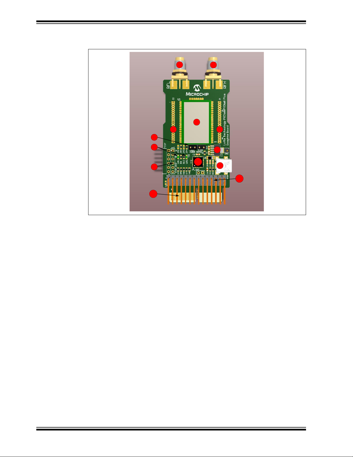
The RN2483 LoRa Technology PICtail/PICtail Plus Daughter Board has the following
features as represented in Figure 1-1:
1. Microchip RN2483 Low-Power Long Range, LoRa
Module
2. SMA connector for 433 MHz band
3. SMA connector for 868 MHz band
4. Solder pads around the module for GPIOs, power pins and communication
signals
5. Supply Current measurement points
6. On-board LDO
7. UART traffic LEDs
8. ICSP header to program the on-board PIC18 MCU
9. USB connector
10. PICtail connection interface
11. PICtail Plus connection interface
12. PIC18 MCU for custom functions
™
Technology Transceiver
2015 Microchip Technology Inc. Advance Information DS50002366A-page 11
Page 12
RN2483 LoRa™ Technology PICtail™/PICtail Plus Daughter Board User’s Guide
2
1
4
5
6
9
3
4
8
7
12
11
10
FIGURE 1-1: RN2483 LORA™ TECHNOLOGY PICtail™/PICtail PLUS
DAUGHTER BOARD
The high-speed UART interface and the GPIO ports are available on the module to
configure, control, and transfer data. The RN2483 LoRa Technology PICtail/PICtail
Plus Daughter Board has PICtail and PICtail Plus connectors to interface with a PIC
®
microcontroller (MCU) on the development boards that support PICtail or PICtail Plus
interface with the required pin mapping. The PICtail board also has an on-board PIC18
MCU available for custom user functions. It is preprogrammed to provide a simple
USB-to-UART serial bridge enabling easy serial connection.
Demonstration of the RN2483 is performed by plugging the daughter board into a USB
port of a PC. The USB port powers the daughter board and enables the user to
communicate using the RN2483’s ASCII commands.
Development of the RN2483 with Microchip’s PIC MCU line is possible via the 28-pin
PICtail connector to a PIC18 Explorer or 30-pin card edge PICtail Plus connector to an
Explorer 16.
DS50002366A-page 12 Advance Information 2015 Microchip Technology Inc.
Page 13

1.3 CONTENTS
The package kit contents contain the following tools as listed in Table 1-1.
TABLE 1-1: RN2483 LORA™ TECHNOLOGY PICtail™/PICtail PLUS
DAUGHTER BOARD
Description Part Number
RN2483 LoRa™ Technology PICtail™/PICtail Plus
Daughter Board
USB Cable —
433 MHz antenna —
868 MHz antenna —
1.4 BOARD CONFIGURATION
Prior plugging the module into the motherboard's socket, ensure that one of the current
measure jumpers, CUR1 or CUR2, are shunted.
PICtail Daughter Board can be powered from two sources, either from one of the
PICtail headers or from USB. Both power sources can be active at the same time.
RF antennas must be connected to the SMA connectors prior attaching power to the
board.
Ensure that the applied power supply voltage does not exceed the board limits.
Figure 1-2, Figure 1-3, and Figure 1-4 show the connection to various development
boards.
Overview
RN-2483-PICtail
FIGURE 1-2: RN2483 LORA™ TECHNOLOGY PICtail™/PICtail PLUS
DAUGHTER BOARD CONNECTED TO EXPLORER 16
DEVELOPMENT BOARD
2015 Microchip Technology Inc. Advance Information DS50002366A-page 13
Page 14

RN2483 LoRa™ Technology PICtail™/PICtail Plus Daughter Board User’s Guide
FIGURE 1-3: RN2483 LORA™ TECHNOLOGY PICtail™/PICtail PLUS
DAUGHTER BOARD CONNECTED TO PIC18 WIRELESS
DEVELOPMENT BOARD
FIGURE 1-4: RN2483 LORA™ TECHNOLOGY PICtail™/PICtail PLUS
DAUGHTER BOARD CONNECTED TO PICDEM™ PIC18
EXPLORER DEMONSTRATION BOARD
DS50002366A-page 14 Advance Information 2015 Microchip Technology Inc.
Page 15

2.1 INTRODUCTION
This chapter describes the hardware requirements for RN2483 LoRa Technology
PICtail/PICtail Plus Daughter Board and also provides the different types of
communication modes.
The module accepts commands via UART interface. Basically, two communication
modes are supported by the daughter board, USB mode and PICtail mode.
PICtail mode gives more computing power to the user program, since motherboards
contain additional MCUs.
This chapter discusses the following topics:
• Communication Modes
• Communication to the Module
• Hardware Description
RN2483 LoRa™ TECHNOLOGY
PICtail™/PICtail PLUS DAUGHTER
BOARD USER’S GUIDE
Chapter 2. Getting Started
2.2 COMMUNICATION MODES
2.2.1 USB mode
USB mode is initiated if the daughter board is connected to a USB port via a mini-USB
cable. In this mode, the on-board PIC18 MCU provides a USB-to-UART bridge.
Supply voltage is provided via USB and the on-board LDO (IC1) which regulates 5V to
the nominal 3.3V.
2.2.2 PICtail mode
PICtail mode is initiated if no USB cable is attached to the board and the board is
plugged into the appropriate motherboard.
Note: User must ensure that PICtail/PICtail Plus port pins are fully compatible to
the pinout of the daughter board.
When USB power is not attached, the on-board PIC18 MCU does not influence UART
communication.
Note: Some motherboards may adjust the supply voltage to the attached MCU
Plug-in Module. Do not exceed the supply voltage limits of the module.
2.2.3 PICtail mode with USB connected
The daughter board can be used in a third mode when it is connected to a PICtail
motherboard while the USB is also connected. It is useful when the user wants to set
the supply voltage from the PICtail connector while the communication must be
continuously active via the USB interface. The on-board PIC18 MCU takes over the
control of the UART interface. In this case, the motherboard is unable to send UART
messages to the module, however, the messages sent by the module appear on the
PICtail UART.
2015 Microchip Technology Inc. Advance Information DS50002366A-page 15
Page 16

RN2483 LoRa™ Technology PICtail™/PICtail Plus Daughter Board User’s Guide
Another case is that the motherboard does not have power supply. In this case, the
motherboard can be powered from the USB together with the daughter board. User
must take care of the maximum output current of the on-board LDO, which is 500 mA.
A short on the jumper JP_RST on the daughter board forces the board to operate in
PICtail mode, although USB remains connected. The jumper JP_RST keeps the
on-board PIC18 MCU in reset state to ensure that USB-to-UART protocol translation is
not performed in this mode. If jumper JP_RST is not shorted, on-board PIC18 MCU has
the priority over the UART communication.
Note: Only 30-pin PICtail Plus connection is detected. If the daughter board is
attached to a 28-pin PICtail connector, the jumper JP_RST has no affect.
2.3 COMMUNICATION TO THE MODULE
In PICtail mode, the Microchip 8/16/32-bit PIC MCUs on the motherboards can run
custom functions and connect to the module using the UART interface, which accepts
ASCII commands from the host.
In USB mode, when the daughter board is connected to the host via USB, the on-board
PIC18 MCU uses the CDC class to create a USB-to-UART bridge device. The host can
run a simple terminal emulator application to issue commands.
2.4 HARDWARE DESCRIPTION
The RF signal path is connected to the SMA edge connectors. The 433 MHz band RF
signal is transmitted through RFL SMA edge connector, whereas RFH SMA connector
is used for the 868 MHz band.
The current consumption measurement of the module is supported by the on-board
current measure jumpers. If jumper CUR1 is shunted, the supply current flows directly
to the module.
There are two ways to measure current consumption:
• A current meter can be connected to CUR1 jumper pins to measure the actual
current consumption of the module. CUR2 must be left open.
• The current consumption graph can be recorded in the time domain by removing
the shunt from CUR1 jumper and shunting CUR2 at the same time. Use a two
channel oscilloscope, which supports subtracting mathematical function. Connect
oscilloscope probes to CUR1 jumper pins while CUR2 jumper is shunted. Set the
oscilloscope to display the difference between the two channels.
All pins of the module can be accessed via through hole pads which is located on both
sides of the module. User can mount two 1.27 mm pitched socket headers if required.
Sockets can connect the module pins to a custom board, whereas the daughter board
provides the power. The through hole pads are classified into two groups which are
located on both sides of the module. Each pad group, J1 and J2, has a dedicated pad
on which power is delivered to the custom board. The supply current is measured
together with the module's supply current. To do this, JP2 must be shorted for J2 and
JP3 for J1.
If the supply current is separated from the module, the other two jumpers must be
shorted. To power the custom board separately, shunt JP1 or JP4.
The on-board PIC18 MCU is programmable via programming port ICSP_IC2. In USB
mode, LD1 and LD2 LEDs indicate communication on the UART.
DS50002366A-page 16 Advance Information 2015 Microchip Technology Inc.
Page 17
Getting Started
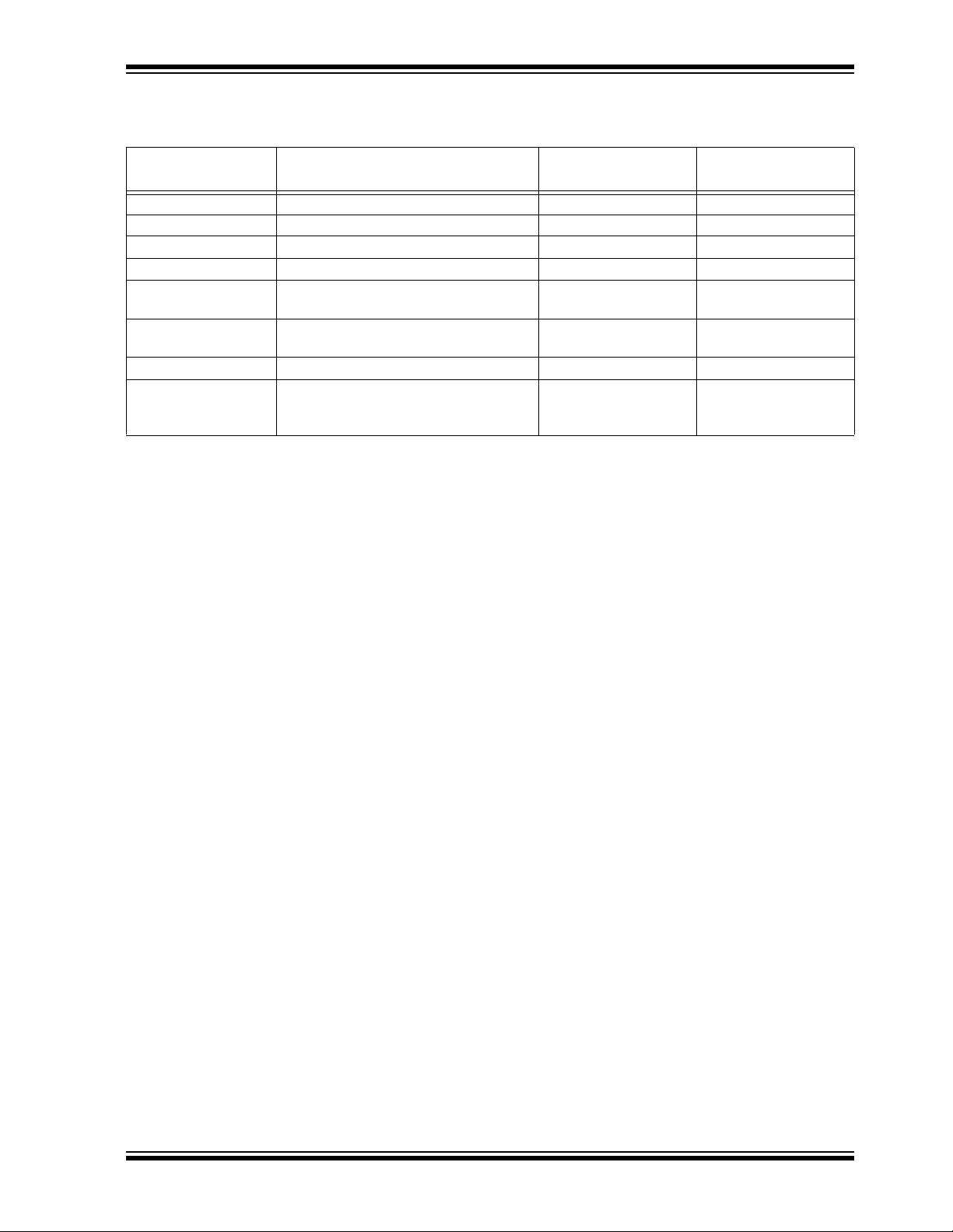
Ta bl e 2- 1 shows the PICtail/PICtail Plus connections to various boards.
TABLE 2-1: PICtail™ AND PICtail PLUS CONNECTIONS
Signal Name Description
+3V3 Positive Supply Rail 26 21, 22
GND Ground Supply Rail 28 9, 10, 16
Module_TX UART transmit output of the module 21 2
Module_RX UART receive input of the module 17 4
Module_RTS UART Hardware handshake output of
the module
Module_CTS UART Hardware handshake input of the
module
PT_Module_RESET Master Clear input of the module 1 6
PT+_SENSE Sensing signal for PICtail Plus connector
(the platform connects this line to GND
when plugged)
(1)
(1)
Pin number on PICtail
connector
419
320
—15
Note 1: Optional handshake lines are supported in future firmware releases.
Pin number on PICtail
Plus connector
2015 Microchip Technology Inc. Advance Information DS50002366A-page 17
Page 18

RN2483 LoRa™ Technology PICtail™/PICtail Plus Daughter Board User’s Guide
NOTES:
DS50002366A-page 18 Advance Information 2015 Microchip Technology Inc.
Page 19

Appendix A. Board Schematic and PCB Details
A.1 INTRODUCTION
This appendix provides the RN2483 LoRa Technology PICtail/PICtail Plus Daughter
Board schematic, PCB layout and Bill of Materials (BOM).
• Board Schematic
• PCB Layout
• Bill of Materials
A.2 BOARD SCHEMATIC
Figure A-1 shows the board schematic.
RN2483 LoRa™ TECHNOLOGY
PICtail™/PICtail PLUS DAUGHTER
BOARD USER’S GUIDE
2015 Microchip Technology Inc. Advance Information DS50002366A-page 19
Page 20

DS50002366A-page 20 Advance Information 2015 Microchip Technology Inc.
+3V3
Current measure points
+3V3_M
GNDGND
GNDGND
GND
Module_RX
Module_TX
Module_CTS
Module_RTS
+3V3_M +3V3_M
GND GND GND
+3V3+3V3
GND
GND
GND
GND
+3V3
+3V3
PT_Module_RESET
+3V3
GND
GND
Module_RX
Module_TX
PT_Module_CTS
Module_CTS
+3V3
GND
+3V3
Module_TX
PT_Module_CTS
Module_RTS
Module_RTS
GND
GND
1
2
3
4
5
6
7
8
9
10
11
12
13
14
15
16
17
18
19
20
J1
Socket 1.27 mm
1
2
3
4
5
6
7
8
9
10
11
12
13
14
15
16
17
18
19
20
J2
Socket 1.27 mm
+3V3_ext1
+3V3_ext2
GP0
GP1
GP2
GP3
GP4
GP5
GP6
GP7
GP8
GP9
GP10
GP11
GP12
GP13
PT_Module_RX
PT_Module_RX
1 2
3 4
5 6
7 8
9 10
11 12
13 14
15 16
17 18
19 20
21 22
23 24
25 26
27 28
29 30
PICTail Plus
RA2/AN2/C2IN+/Vref-
1
RA3/AN3/C1IN+/VREF+
2
RA4/C1OUT/SRQ/T0CKI
3
RA5/AN4/C2OUT/SRNQ/HLVDIN/SS
4
RA7/OSC1/CLKI
6
RA6/OSC2/CLKO
7
RC0/SOSCO/T1CKI/T3CKI/T3G/IOCC0
8
RC1/CCP2/SOSCI/IOCC1
9
RC2/AN14/CTPLS/CCP1/P1A/IOCC2
10
VUSB
11
D-
12
D+
13
RC6/AN18/TX/CK/IOCC6
14
RC7/RX/DT/SDO/IOCC7
15
Vss
Vdd
17
RB0/AN12/SRI/FLT0/SDI/SDA/INT0
18
RB1/AN10/C12IN3-/P1C/SCK/SCL/INT1
19
RB2/AN8/CTED1/P1B/INT2
20
RB3/AN9/C12IN2-/CTED2/CCP2/SDO
21
RB4/AN11/P1D/IOCB4
22
RB5/AN13/T1G/T3CKI/IOCB5
23
RB6/IOCB6/PGC
24
RB7/IOCB7/PGD
25
MCLR/VPP/RE3
26
RA0/AN0/C12IN0-
27
RA1/AN1/C12IN1-
28
EP
29
5,16
-
RA3
/AN3
/C1IN+/V
R
0
CKI
5
/
/C2
OUT/
RA7
/OSC1
/C
RA6
OSC2/CLKO
RC0/SOSCO/T1CKI/T3
CKI/T3
G/IOCC0
RC1/CCP2/SOSC
OCC
RC2
/
4
/C
S/CCP1
/
OCC2
VUS
D-
D+
RC6
/
8
/TX/CK/
6
RC7
/RX/DT/SDO/IOCC
Vss
Vd
d
0
/AN1
/SRI/
IN3
1
C/SCK/SC
RB2
/
1
/P1
B/
9
/C
O
RB4
/
1
/P1
D/IOC
RB5
/AN13/
5
R
GC
RB7
/
7
/PGD
2
IN0
1
/
2
IN1
IC2
PIC18LF25K50-I/ML
Module_RX
Module_TX
Module_CTS
Module_RTS
+3V3
GND
IC2_ICSP_MCLR
IC2_ICSP_PGD
IC2_ICSP_PGC
Module_RESET
GND
PT+_SENSE
PT+_SENSE IC2_MCLR
GND
USB_D+
USB_D-
+5V_USB
USB_DET
+5V_LDO
GND
+3V3
+3V3
GND
1
UART_RTS
2
UART_CTS
3
RESERVED
4
RESERVED
5
UART_TX
6
UART_RX
7
GND
8
GND
11
VDD
12
NC
15
NC
16
NC
17
NC
18
NC
19
GND
20
GND21GND
22
RFH
23
GND
24
RFL
25
GND26GND
27
GND
28
NC
29
TEST0
30
TEST1
31
RESET
32
GND
33
VDD
34
GPIO0
35
GND
41
NC
42
GND
47
GND
U
S
U
_
CTSRESERV
U
TX
_
R
D
GND
VDD
CNC
C
C
C
D
NNNLN
N
D
C
T
GND
VDD
GPIO
GND
C
GND
GPIO1
36
GPIO2
37
GPIO3
38
GPIO4
39
GPIO5
40
GPIO6
43
GPIO7
44
GPIO8
45
GPIO9
46
GPIO11
13
GPIO10
14
GPIO12
10
GPIO13
9
U1
RN2483
0.1uF
25V
0603
C4
10uF
10V
0603
C5
0.01uF
50V
0603
C6
1uF
50V
0603
C3
1uF
50V
0603
C1
0.47uF
25V
0603
C2
1R
0603
1%
R1
1.5k
0603
1%
R2
1.5k
0603
1%
R3
220R
0603
1%
R4
220R
0603
1%
R5
220R
0603
1%
R6
220R
0603
1%
R9
220R
0603
1%
R10
100R
0402
1%
R7
4.7k
0603
1%
R8
4.7uF
6.3V
0603
C8
G
LD1
G
LD2
Gnd
Vout
4
Pgd5EN
1
V
u
t
Pg
d
N
Vin
2
Gnd
3,6
IC1
MCP1825T-SOT-223-5
B0520WS
D1
123450
ID D+ D-
+5VGND
USB MINI-B Female
USB
RFL RFH
TP LOOP White
GND
CUR1
CUR2
JP_RST
1
2
3
4
5
6
HDR-2.54 Ma le 1x6
ICSP_IC2
PT_Module_RESET
GND
1
2
3
4
5
6
TEST
HDR-2.54 Ma le 1x6 RA
1112
1314
1516
1718
1920
2122
2324
2526
2728
12345678910
RF-PICtail
PICTail
HDR_M_2.54_2x14_RA_SUL_PBC14DBDN
0R
0603
JPI
0R
0603
JP1
0R
0603
JP2
0R
0603
JP3
0R
0603
JP4
Note: Shaded components are not populated by default.
FIGURE A-1: RN2483 LORA™ TECHNOLOGY PICtail™/PICtail PLUS DAUGHTER BOARD SCHEMATIC
o
RN2483 LoRa™ Technology PICtail™/PICtail Plus Daughter Board User’s Guide
I/I
TPL
E
IOCC
RA
RB
B1/AN10/C12
RB3/AN
1
P1A/I
7
RA2/AN2/C2IN+/Vref
A4/C1OUT/SRQ/T
AN4
FLT0/SDI/SDA/INT0
-/P
AN8/CTED
12IN2-/CTED2/CCP2/SD
RA0/AN0/C1
RA
AN1/C1
REF+
SRNQ/HLVDIN/SS
/
L/INT1
INT2
AN1
T1G/T3CKI/IOCB
B6/IOCB6/P
IOCB
CLR/VPP/RE3
LKI
B4
GN
N
TEST0
TEST1
RESE
0
N
GN
N
N
N
N
UART
ART_
RESERVED
ART
ART_RT
GN
X
ED
B
AN1
AN1
Page 21

Board Schematic and PCB Details
A.3 PCB LAYOUT
LoRa Technology PICtail/PICtail Plus Daughter Board is a 2-layer, FR4, 1.55
mm, plated through hole PCB construction.
Figure A-2 through Figure A-4 illustrate the PCB layers, Figure A-5 shows the
assembly drawing of LoRa Technology PICtail/PICtail Plus Daughter Board.
FIGURE A-2: RN2483 LORA™ TECHNOLOGY PICtail™/PICtail PLUS DAUGHTER BOARD TOP
SILKSCREEN
FIGURE A-3: RN2483 LORA™ TECHNOLOGY PICtail™/PICtail PLUS DAUGHTER BOARD TOP
COPPER
2015 Microchip Technology Inc. Advance Information DS50002366A-page 21
Page 22

RN2483 LoRa™ Technology PICtail™/PICtail Plus Daughter Board User’s Guide
FIGURE A-4: RN2483 LORA™ TECHNOLOGY PICtail™/PICtail PLUS DAUGHTER BOARD
BOTTOM COPPER (BOTTOM VIEW)
DS50002366A-page 22 Advance Information 2015 Microchip Technology Inc.
Page 23

Board Schematic and PCB Details
FIGURE A-5: RN2483 LORA™ TECHNOLOGY PICtail™/PICtail PLUS DAUGHTER BOARD TOP
ASSEMBLY
2015 Microchip Technology Inc. Advance Information DS50002366A-page 23
Page 24

RN2483 LoRa™ Technology PICtail™/PICtail Plus Daughter Board User’s Guide
A.4 BILL OF MATERIALS
TABLE A-1: RN2483 LORA™ TECHNOLOGY PICtail™/PICtail PLUS DAUGHTER BOARD BILL OF
MATERIALS (BOM)
Reference Value Description Vendor Vendor P/N
C1, C3 1uF CAP, 0603, 25V, 10%, X7R Murata Electronics
North America
C2 470nF CAP, 0603, 25V, 10%, X7R Murata Electronics
North America
C4 100nF CAP, 0603, 25V, Y5V Yageo CC0603ZRY5V8BB104
C5 10uF CAP, 0603, 6.3V, 20%, X5R Murata Electronics
North America
C6 10nF CAP, 0603, 50V, 10%, X7R Murata Electronics
North America
C8 4.7uF CAP, 0603, 6.3V, 10%, X5R Murata Electronics
North America
CUR1,
CUR2
D1 — DIODE SCHOTTKY 20V 0.5A
GND — CONN Pin1 Keystone 5012
IC1 — IC MCP1825-3302E/DC Microchip MCP1825-3302E/DC
IC2 — IC PIC18LF25K50-I/ML Microchip PIC18LF25K50-I/ML
JP2, JP4 — RES 0 OHM 0603 JUMPER 2P Vishay Dale CRCW06030000Z0EA
JP-S1 — JUMPER SHUNT 2POS 2.54
LD1, LD2 — LED 565NM GRN DIFF 0603 Lumex
PICTail — CONN Pin14x2 2.54 mm right
R1 1.00 Ohm RES 0603 1/10W 1% Yageo RC0603FR-071RL
R2 1.50 kOhm RES 0603 1/10W 1% Vishay Dale CRCW06031K50FKEA
R3 2.70 kOhm RES 0603 1/10W 1% Vishay Dale CRCW06032K70FKEA
R4, R5, R6,
R9, R10
R7 100 Ohm RES 0603 1/10W 1% Vishay Dale CRCW0603100RFKEA
R8 4.70 kOhm RES 0603 1/10W 1% Vishay Dale CRCW06034K70FKEA
RFH, RFL — CONN JACK SMA 50 OHM
U1 — RF module RN2483 LoRa EU
USB — CONN MINI B USB R/A SMD Hirose UX60-MB-5ST
— CONN Pin2 2.54 mm_jumper Harwin Inc M20-9990245
Diodes Inc B0520LW-7-F
SOD123
TE Connectivity 382811-8
mm LOPRO GOLD
Opto/Components Inc
Sullins Connector
angle (PBC14DBDN)
220 Ohm RES 0603 1/10W 1% Vishay Dale CRCW0603220RFKEA
EDGE MOUNT
433/868MHz
Solutions
Cinch Connectivity
Solutions Johnson
Microchip RN2483
GRM188R71E105KA12D
GRM188R71E474KA12D
GRM188R60J106ME47D
GRM188R71H103KA01D
GRM188R60J475KE19D
SML-LX0603GW-TR
PBC14DBDN
142-0711-821
DS50002366A-page 24 Advance Information 2015 Microchip Technology Inc.
Page 25

Worldwide Sales and Service
AMERICAS
Corporate Office
2355 West Chandler Blvd.
Chandler, AZ 85224-6199
Tel: 480-792-7200
Fax: 480-792-7277
Technical Support:
http://www.microchip.com/
support
Web Address:
www.microchip.com
Atlanta
Duluth, GA
Tel: 678-957-9614
Fax: 678-957-1455
Austin, TX
Tel: 512-257-3370
Boston
Westborough, MA
Tel: 774-760-0087
Fax: 774-760-0088
Chicago
Itasca, IL
Tel: 630-285-0071
Fax: 630-285-0075
Cleveland
Independence, OH
Tel: 216-447-0464
Fax: 216-447-0643
Dallas
Addison, TX
Tel: 972-818-7423
Fax: 972-818-2924
Detroit
Novi, MI
Tel: 248-848-4000
Houston, TX
Tel: 281-894-5983
Indianapolis
Noblesville, IN
Tel: 317-773-8323
Fax: 317-773-5453
Los Angeles
Mission Viejo, CA
Tel: 949-462-9523
Fax: 949-462-9608
New York, NY
Tel: 631-435-6000
San Jose, CA
Tel: 408-735-9110
Canada - Toronto
Tel: 905-673-0699
Fax: 905-673-6509
ASIA/PACIFIC
Asia Pacific Office
Suites 3707-14, 37th Floor
Tower 6, The Gateway
Harbour City, Kowloon
Hong Kong
Tel: 852-2943-5100
Fax: 852-2401-3431
Australia - Sydney
Tel: 61-2-9868-6733
Fax: 61-2-9868-6755
China - Beijing
Tel: 86-10-8569-7000
Fax: 86-10-8528-2104
China - Chengdu
Tel: 86-28-8665-5511
Fax: 86-28-8665-7889
China - Chongqing
Tel: 86-23-8980-9588
Fax: 86-23-8980-9500
China - Dongguan
Tel: 86-769-8702-9880
China - Hangzhou
Tel: 86-571-8792-8115
Fax: 86-571-8792-8116
China - Hong Kong SAR
Tel: 852-2943-5100
Fax: 852-2401-3431
China - Nanjing
Tel: 86-25-8473-2460
Fax: 86-25-8473-2470
China - Qingdao
Tel: 86-532-8502-7355
Fax: 86-532-8502-7205
China - Shanghai
Tel: 86-21-5407-5533
Fax: 86-21-5407-5066
China - Shenyang
Tel: 86-24-2334-2829
Fax: 86-24-2334-2393
China - Shenzhen
Tel: 86-755-8864-2200
Fax: 86-755-8203-1760
China - Wuhan
Tel: 86-27-5980-5300
Fax: 86-27-5980-5118
China - Xian
Tel: 86-29-8833-7252
Fax: 86-29-8833-7256
ASIA/PACIFIC
China - Xiamen
Tel: 86-592-2388138
Fax: 86-592-2388130
China - Zhuhai
Tel: 86-756-3210040
Fax: 86-756-3210049
India - Bangalore
Tel: 91-80-3090-4444
Fax: 91-80-3090-4123
India - New Delhi
Tel: 91-11-4160-8631
Fax: 91-11-4160-8632
India - Pune
Tel: 91-20-3019-1500
Japan - Osaka
Tel: 81-6-6152-7160
Fax: 81-6-6152-9310
Japan - Tokyo
Tel: 81-3-6880- 3770
Fax: 81-3-6880-3771
Korea - Daegu
Tel: 82-53-744-4301
Fax: 82-53-744-4302
Korea - Seoul
Tel: 82-2-554-7200
Fax: 82-2-558-5932 or
82-2-558-5934
Malaysia - Kuala Lumpur
Tel: 60-3-6201-9857
Fax: 60-3-6201-9859
Malaysia - Penang
Tel: 60-4-227-8870
Fax: 60-4-227-4068
Philippines - Manila
Tel: 63-2-634-9065
Fax: 63-2-634-9069
Singapore
Tel: 65-6334-8870
Fax: 65-6334-8850
Taiwan - Hsin Chu
Tel: 886-3-5778-366
Fax: 886-3-5770-955
Taiwan - Kaohsiung
Tel: 886-7-213-7828
Taiwan - Taipei
Tel: 886-2-2508-8600
Fax: 886-2-2508-0102
Thailand - Bangkok
Tel: 66-2-694-1351
Fax: 66-2-694-1350
EUROPE
Austria - Wels
Tel: 43-7242-2244-39
Fax: 43-7242-2244-393
Denmark - Copenhagen
Tel: 45-4450-2828
Fax: 45-4485-2829
France - Paris
Tel: 33-1-69-53-63-20
Fax: 33-1-69-30-90-79
Germany - Dusseldorf
Tel: 49-2129-3766400
Germany - Munich
Tel: 49-89-627-144-0
Fax: 49-89-627-144-44
Germany - Pforzheim
Tel: 49-7231-424750
Italy - Milan
Tel: 39-0331-742611
Fax: 39-0331-466781
Italy - Venice
Tel: 39-049-7625286
Netherlands - Drunen
Tel: 31-416-690399
Fax: 31-416-690340
Poland - Warsaw
Tel: 48-22-3325737
Spain - Madrid
Tel: 34-91-708-08-90
Fax: 34-91-708-08-91
Sweden - Stockholm
Tel: 46-8-5090-4654
UK - Wokingham
Tel: 44-118-921-5800
Fax: 44-118-921-5820
01/27/15
DS50002366A-page 25 2015 Microchip Technology Inc.
Page 26

Mouser Electronics
Authorized Distributor
Click to View Pricing, Inventory, Delivery & Lifecycle Information:
Microchip:
RN-2483-PICTAIL
 Loading...