

Page 1
Technical Note RN-111b-UG-1.0
WiFLy RN-111B
802.11b “wifi” wireless LAN – OEM Module
Integration Guide and Users Manual
Version 1.16
June 16, 2008
Copyright © 2008 Roving Networks, Inc.
The contents of this document can be changed by Roving networks without prior notice
and do not constitute any binding undertakings from Roving networks. Roving networks
is not responsible under any circumstances for direct, indirect, unexpected damage or
consequent damage that is caused by this document.
Page 2

Roving Networks Wifly RN-111B User Guide Version 1.16
All rights reserved.
Release: 1-02-08
Document version: 1.0
Document number: RN-Wifly-UserGuide-1.0
Printed in the United States of America.
Trademarks
Registered trademarks from other companies are:
www.rovingnetworks.com
support@rovingnetworks.com
Phone 408-395-6539
- 2 -
Page 3

Roving Networks Wifly RN-111B User Guide Version 1.16
Federal Communications Commission (FCC) Statement
15.21
You are cautioned that changes or modifications not expressly approved by the part
responsible for compliance could void the user’s authority to operate the equipment.
15.105(b)
This equipment has been tested and found to comply with the limits for a Class B digital
device, pursuant to part 15 of the FCC rules. These limits are designed to provide
reasonable protection against harmful interference in a residential installation. This
equipment generates, uses and can radiate radio frequency energy and, if not installed
and used in accordance with the instructions, may cause harmful interference to radio
communications. However, there is no guarantee that interference will not occur in a
particular installation. If this equipment does cause harmful interference to radio or
television reception, which can be determined by turning the equipment off and on, the
user is encouraged to try to correct the interference by one or more of the following
measures:
-Reorient or relocate the receiving antenna.
-Increase the separation between the equipment and receiver.
-Connect the equipment into an outlet on a circuit different from that to which the
receiver is connected.
-Consult the dealer or an experienced radio/TV technician for help.
Operation is subject to the following two conditions:
1) this device may not cause interference and
2) this device must accept any interference, including interference that may cause
undesired
operation of the device.
FCC RF Radiation Exposure Statement:
This equipment complies with FCC radiation exposure limits set forth for an uncontrolled
environment. End users must follow the specific operating instructions for satisfying RF
exposure compliance. This transmitter must not be co-located or operating in conjunction
with any other antenna or transmitter.
www.rovingnetworks.com
support@rovingnetworks.com
Phone 408-395-6539
- 3 -
Page 4

Roving Networks Wifly RN-111B User Guide Version 1.16
Industry Canada (IC) Statement
15.21
You are cautioned that changes or modifications not expressly approved by the part
responsible for compliance could void the user’s authority to operate the equipment.
15.105(b)
This equipment has been tested and found to comply with the limits for a Class B digital
device, pursuant to part 15 of the IC rules. These limits are designed to provide
reasonable protection against harmful interference in a residential installation. This
equipment generates, uses and can radiate radio frequency energy and, if not installed
and used in accordance with the instructions, may cause harmful interference to radio
communications. However, there is no guarantee that interference will not occur in a
particular installation. If this equipment does cause harmful interference to radio or
television reception, which can be determined by turning the equipment off and on, the
user is encouraged to try to correct the interference by one or more of the following
measures:
* Reorient or relocate the receiving antenna.
* Increase the separation between the equipment and receiver.
* Connect the equipment into an outlet on a circuit different from that to which the
receiver is connected.
* Consult the dealer or an experienced radio/TV technician for help.
Operation is subject to the following two conditions:
1) this device may not cause interference and
2) this device must accept any interference, including interference that may cause
undesired operation of the device.
IC RF Radiation Exposure Statement:
This equipment complies with IC radiation exposure limits set forth for an unc ontrolled
environment. End users must follow the specific operating instructions for satisfying RF
exposure compliance. This transmitter must not be co-located or operating in conjunction
with any other antenna or transmitter.
www.rovingnetworks.com
support@rovingnetworks.com
Phone 408-395-6539
- 4 -
Page 5

Table of Contents
1.1. RN-111B Overview
1. About WiFLY RN-111B 4
1.1. RN-111B Overview 4
1.2. RN-111B Features 4
1.3. RN-111B Options 5
1.4. RN-111B Specificattions 5
1.5. RN-111B Block Diagram 6
1.6. RN-111B Electrical Characteristics 6
1.7. RN-111B Operating and Environmental Conditions 7
1.8. RN-111B Dimensions 7
1.9. RN-111B Pin Description 7
2. Introduction 8
2.1. Hardware interfaces 8
2.2. Configuration 9
2.3. LED indications 9
3. RN-111B Command Reference 10
3.1. Set Commands 11
3.2. Get Commands 14
3.3. Status Commands 14
3.4. Action Commands 15
3.5. File IO Commands 15
4. System timers and other features 16
4.1. Wake on SENSE inputs 16
4.2. Wake on UART 16
4.3. Setting diagnostic print levels 17
4.4. Setting PIO directions 18
4.5. Setting alternate IO functions 18
5. FTP Upgrade and Image Storing 19
6. Factory Default Power up Settings 20
Roving Networks Wifly RN-111B User Guide Version 1.16
www.rovingnetworks.com
support@rovingnetworks.com
Phone 408-395-6539
- 5 -
Page 6

Roving Networks Wifly RN-111B User Guide Version 1.16
1.1. RN-111B Overview
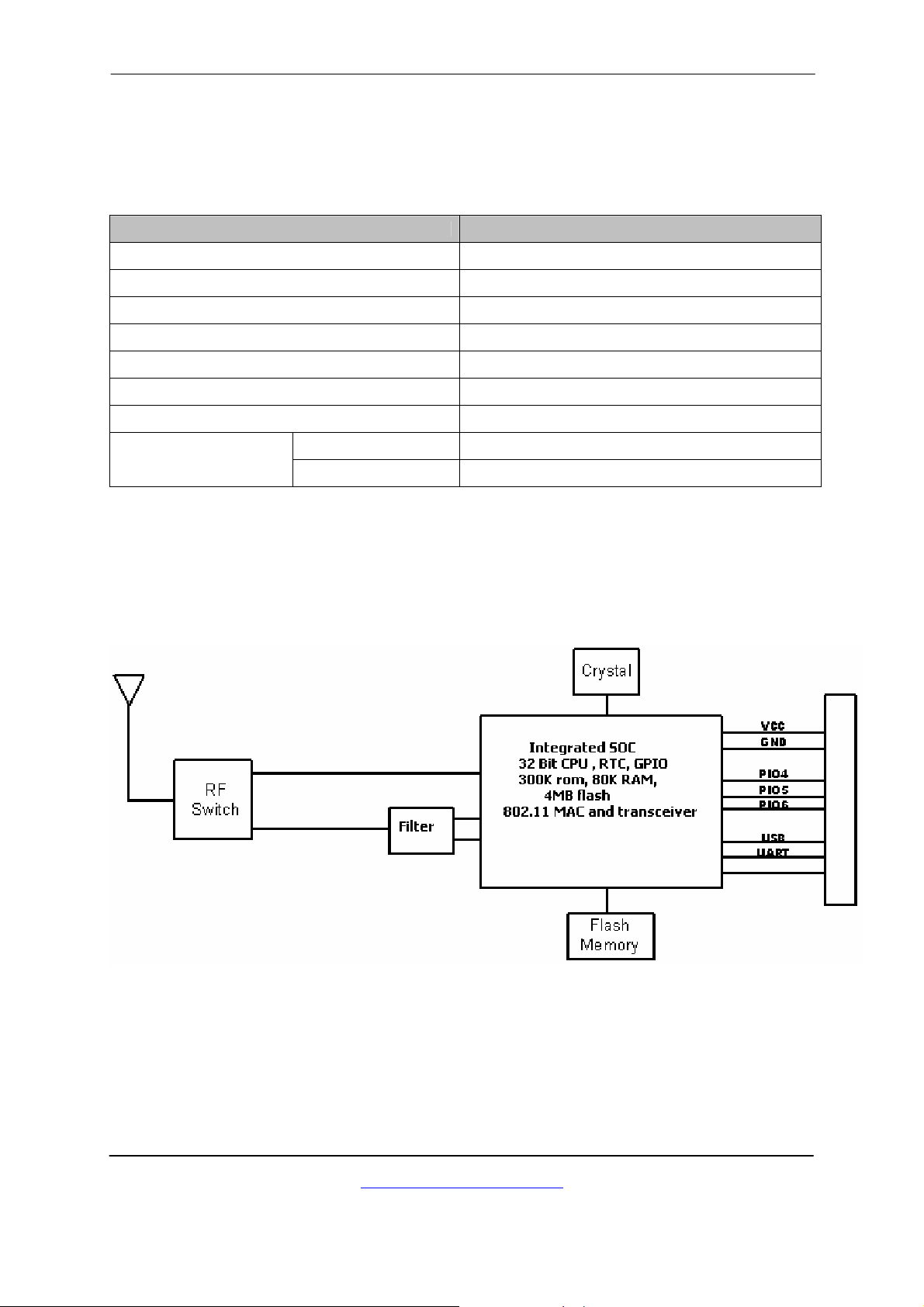
The RN-111b “WiFly” radio module is a complete, stand alone, embedded wireless
LAN access device. The device has on board TCP/IP stack and applications. Requiring
only 4 pins (POWER, TX, RX, GND) to design in. Once initial configuration is set, the
radio can automatically access the WiFi network and send/receive serial data over UART.
• Fully Qualified 2.4GHz IEEE 802.11b Wireless LAN radio module.
• 32bit CPU, 230K ROM, 80KRAM, 4MB on board flash.
• On board ECOS -OS, TCP/IP stacks.
• 3.3V UART and SPI interfaces available to various applications.
• Accepts wide voltage range input 3.3V – 12VDC.
• Multiple Antennae options, SMA, U.FL, ceramic Chip, ¼ wave wire.
• Conforms to FCC, CE and the EMI standard of each country.
• Modular Approval: FCC ID: T9J-RN111b, ICS: 6514A-RN111b, CE: 0681
• RoHS compliance.
1.2. RN-111B Features
• Baud rate speeds: 1200bps up to 921.6Kbps and non-standard baudrates.
• Ultra low power consumption (110mA TX, 40ma RX, 12uA deep sleep).
• Real time clock for timestamping, auto-sleep and auto-wake modes.
• UART local configuration using simple ASCII commands.
• Over the air firmware upgrade (FTP), and data file upload.
• 3 on board LEDs for status.
• 6 Programmable IO pins, 8 analog sensor inputs.
• On board flash can be used to store multiple applications, and for data logging,
and stored data forwarding at intervals to the networks.
• Small-form factor low profile radio modem 25mm x 36mm x 5mm.
• 32 pin Standard 2mm DIP socket pin spacing.
1.3 RN-111B Options
• Larger flash memory (up to 16Mb) for data logging.
• On board boost regulator can power from low voltage 2-3V battery source.
• SMA, Chip, U.FL or wire ANT.
www.rovingnetworks.com
support@rovingnetworks.com
Phone 408-395-6539
- 6 -
Page 7
1.4. RN-111B Specifications
Item Specifications
Frequency 2402 ~ 2480MHz
Roving Networks Wifly RN-111B User Guide Version 1.16
Modulation
Channel intervals 5MHz
Number of channels 13CH
Transmission rate (over the air) 11/5.5/2/1 Mpbs
Receive sensitivity -85dBm typ.
Output level (Class1) 12dBm max.
Dimensions
With antenna
1.5. RN-111B Block Diagram
DSSS(CCK-11, CCK-5.5, DQPSK-2, DBPSK-1)
25.4(W)X36(L)X5(H)mm
www.rovingnetworks.com
support@rovingnetworks.com
Phone 408-395-6539
- 7 -
Page 8

Roving Networks Wifly RN-111B User Guide Version 1.16
1.6 RN-111B Electrical Characteristics
Min Typ. Max. Unit
Supply Voltage VIN 4.0 5.0 12 VDC
Supply Voltage VDD 3.0 3.3 3.6 VDC
Supply Voltage (VBATT option) 2.0 3.0 3.3 VDC
Average power consumption
Standby/Idle (default settings) - 35 - mA
Sleep 12 20 900 uA (micro)
Connected(idle, RX) 40 mA
Connected( TX) 110 180 mA
1.7 RN-111B Operating and Environmental Conditions
Operating Temperature Range -40 oC ~ 85 oC
Storage Temperature Range -40 oC ~ 85 oC
Relative Humidity (Operating) ≤90%
Relative Humidity (Storage) ≤90%
www.rovingnetworks.com
support@rovingnetworks.com
Phone 408-395-6539
- 8 -
Page 9

1.8 RN-111B Dimensions
Roving Networks Wifly RN-111B User Guide Version 1.16
1.9 RN-111B Pin Description
Pin Pin Name Pin Pin Name
1 NO CONNECT 32 GND
2 VDD_SW (NO CONNECT) 31 SENSE-1 (WAKE GPIO)
3 SENSE-5 30 SENSE-2 (WAKE GPIO)
4 SENSE-6 29 SENSE-3 (WAKE GPIO)
5 SENSE-7 28 SENSE-4 (WAKE GPIO)
6 SENSE-8 27 TX – data output
7 PIO6 (RED LED) 26 RX – data input
8 PIO9 (factory reset ) 25 CTS (PIO2) input
9 NO CONNECT 24 RTS (PIO3) output
10 NO CONNECT 23 PIO4 (GREEN LED)
11 RESET* (active LOW ) 22 PIO5 (YELLOW LED)
12 SHUTDOWN (NO CONNECT) 21 SPI_MI
13 VIN (3.6-16VDC) 20 SPI_CS
14 VREG (3.3V LDO output) 19 SPI_CK
15 VBATT (TIE to VREG) 18 SPI_MO
16 GND 17 VDD (3.3V )
*** NOTE: Any unused pins should be left floating.
www.rovingnetworks.com
support@rovingnetworks.com
Phone 408-395-6539
- 9 -
Page 10

Roving Networks Wifly RN-111B User Guide Version 1.16
2. Introduction
Scope
This Integration and Users Guide, along with the RN-111b module have been developed
to assist users in embedding Wifi technology into their serial, SPI, and sensor devices.
The goal is to make the implementation of embedded Wifi wireless networks as seamless
and easy as possible. This document will explain how to setup and establish
communications between the RN-111b and Wifi enabled networks for data applications.
2.1 Hardware Interface
There are 3 options to power the RN-111b.
1. Supply 3.6 to 16VDC power to VIN (pin 13). Tie VREG (pin 14) to VBATT(pin 15).
2. Apply 3.3VDC regulated power to VDD (pin 17).
3. Apply battery = 2.0 to 3.0VDc to VBATT (pin 15).
If VIN is powered, VREG will supply 3.3VDC output and can be used for other circuits,
with a current limitation of 50 ma.
Reset is active LOW, is optional and does not need to be connected. There is a built in
voltage monitor that will pull Reset LOW (open drain FET) if the input voltage drops
below 2.7VDC. If external reset is desired, use an OPEN DRAIN driver and do not drive
the Reset pin to any voltage > 1.0 Vdc.
Warning: Do NOT exceed the voltage ratings on the 3.3V pins, damage to the module
will result.
Important Notes:
#1: RESET input is a low voltage (1.2VDC ) input, with a 10K pullup and built in
power monitor circuits. If external reset is desired, use pull down (open drain
or collector) only.
#2: The Sensor inputs SENS1-7 are extremely sensitive to over voltage. Under
no conditions should these pins be pulled high above 1.2VDC. Placing any
voltage above this will permanently damage the radio module and render it
useless.
#3: Placing 5VDC or any voltage above 3.3Vdc into the VDD pins of the module
will permanently damage the radio module. Be sure to use the VIN = pin 13
power pin for any power supplied that is > 3.3VDC.
#4: Placing 3.3Vdc into the PIO’s while they are set as outputs will permanently
damage the radio modules. The failure mode is a short across GND and VCC.
Use a 10KΩ resistor in series or a 10KΩ pull up resistor for input and output
PIO’s respectively.
• Connect a common ground when using the external TX, RX inputs.
• For a 3 wire DB-9 interface (tx, rx, gnd only) connect/short CTS to RTS, Factory
default is hardware flow control disabled, CTS and RTS not connected.
• When using a 5.0Vdc Input, PIO’s require a 10K ohm series resistor. PIO’s are 0-
3.3Vdc not 5 volt tolerant.
www.rovingnetworks.com
support@rovingnetworks.com
Phone 408-395-6539
- 10 -
Page 11

Roving Networks Wifly RN-111B User Guide Version 1.16
2.2 Configuration
Command Mode (vs Normal Data mode)- Upon powerup, the device will be in data
mode. To enter command mode, The characters “$$$” must be sent. The device will
respond with “CMD”. To exit command mode, send “exit<cr>”. The dev ice will respond
with “EXIT”. Parameters, such as the SSid, Channel, IP address, Serial Port settings,
and all other settings can be viewed and configured. While in command mode, the
device will accept ASCII bytes as commands.
Use a normal RS-232 pass through cable from PC passing ASCII characters through the
terminal to the RN-111b. The communications settings should match the settings used
when RN-111b connects, for example: the default is 115,200bps, 8 bits, No Parity, 1
stop bit, and hardware flow control disabled.
Run your favorite terminal emulator, Roving Networks provides a free one, Teraterm, at
http://www.rovingnetworks.com/support/teraterm.zip
.
Type “$$$” on your emulator. You should see “CMD” returned to you. This will verify
that your cable and comm. settings are correct. Most valid commands will return an
“AOK”, response, and invalid ones will return an Error description.
Commands that are not recognized will return a “ERROR: Unknown Cmd”.
To exit command mode, type “exit“<cr>.
NOTE1 :
You can enter command mode locally over the serial port at any time when not
connected, and also when connected if the appropriate settings are enabled.
2.3 LED indications
Condition GREEN YELLOW RED LED
ON Solid CONNECTED over TCP NOT ASSOCIATED
Fast BLink NO IP ADDRESS
Slow Blink IP ADDRESS OK ASSOCIATED, but no Internet
OFF NO power ASSOCIATED and Internet OK
WiFI Receive
Packet
www.rovingnetworks.com
support@rovingnetworks.com
Phone 408-395-6539
- 11 -
Page 12

Roving Networks Wifly RN-111B User Guide Version 1.16
3.0 WiFLY Command Reference
The commands begin with a keyword, and have optional additional parameters, generally
space delimited. Commands and options are case sensitive. hex input data can be upper
or lower case. String text data, such as SSID, are also case sensitive.
The first keyword is fully decoded, and the optional parameters can be short-formed.
For example,
set uart baudrate 115200 is valid,
set uart b 115200 is also valid,
set u b 115200 is also valid, however,
s uart baudrate 115200 is NOT valid.
ENTERING VALUES
Numbers can be entered as either decimal, (like 115200 above ) or HEX. To enter HEX,
use 0x<value>. For example, the HEX value FF would be entered as 0xFF.
Commands fall into 5 general categories:
3.1 SET COMMANDS -Take effect immediately, permanently (save command issued).
3.2 GET COMMANDS -Retrieve the permanently stored information for display to user.
3.3 STATUS COMMANDS -See what is going on with the interface, IP status, etc.
3.4 ACTION COMMANDS- Perform action such as scan, connect, disconnect, etc.
3.5 FILE IO COMMANDS - Upgrade, load and save configuration, delete files, etc.
IMPORTANT: HOW CONFIGURATION WORKS
When the system boots, all configuration data is loaded into RAM variables from the file
called “config”. The set commands actually only modify the RAM copy of variables in the
system. This allows temporary change of parameters “on the fly” to test features,
minimizes power usage and saves on flash re-write cycles.
Once all configuration is complete, the user should be sure t o use the save command to
store the configuration data, otherwise it will not take effect upon reboot or reset.
Multiple configurations can be stored by using th e save <filename> command, and
these configurations can be loaded using the load <filename> command. These files can
be upload to remote FTP site, such that once a desired configuration is created, it can
quickly be copied into additional devices (cloning).
www.rovingnetworks.com
support@rovingnetworks.com
Phone 408-395-6539
- 12 -
Page 13

Roving Networks Wifly RN-111B User Guide Version 1.16
3.1. SET COMMANDS
These commands begin with “set”. There are 6 major categories.
1. COMM- communication and data transfer, timers, matching chars.
2. IP -IP settings.
3. SYS - system settings such as sleep and wake timers.
4. TIME - timer server settings.
UART - serial port settings such as baudrate and parity.
5.
6.
WLAN - wireless interface settings, such as ssid, chan, and security options.
COMM PARAMETERS – TCP connection status strings
set comm close <string> sets the string to send locally when the port is closed.
If no string is desired, use the command set comm close (without the parameter)
set comm open <string> sets the string to send locally when the port is opened.
set comm remote <string> sets the number of bytes to receive before forwarding.
COMM PARAMETERS – receive data forwarding
set comm idle <secs> sets the idle disconnect timer in seconds, causes
disconnect if no transmit or receive data is seen.
set comm match <value> sets the decimal value of the matching character to
search for to initiate forwarding. 0 disables.
set comm size <value> sets the number of bytes to receive before forwarding
0-1 forwards immediately. maximum value = 255 bytes.
set comm time <num *10ms> sets the number of 10 millisecond intervals after a
byte is received to begin forwarding data. 0 disables.
IP PARAMETERS
set ip address <addr> sets the IP address. Numbers are SPACE delimited.
Example : “set ip a 10 10 10 2”
set ip dchp <0,1> Enable or disable DHCP client.
set ip gateway <addr> sets the gateway address.
set ip host <addr> sets the remote host address.
set ip localport <num> sets the local port number.
set ip netmask <value> sets the netmask.
set ip protocol <0,1,2> sets the protocol. 0=UDP, 1=TCP client, 2= TCP server.
www.rovingnetworks.com
support@rovingnetworks.com
Phone 408-395-6539
- 13 -
Page 14

Roving Networks Wifly RN-111B User Guide Version 1.16
set ip remote <value> sets the remote host port number.
set ip ftp <addr> sets the ftp server address.
set ip uport <num> sets the ftp server port number.
SYSTEM PARAMETERS
set sys autoconn <secs> TCP mode: sets the auto-connect TCP timer. 0 disables.
set sys autosleep <num *10ms> UDP mode: sets the auto-sleep timer. 0 disables.
set sys iofunc <value> sets the IO port alternate functions. Bit-mapped value.
set sys mask <mask> sets the IO port direction mask. Bit-mapped value.
set sys printlvl <value> sets numerous print functions. Bit-mapped value.
set sys output <value> <mask> sets output PIO pins to HIGH or LOW.
Bit-mapped value. Optional mask only sets a subset of pins.
set sys sleep <secs> sets the sleep timer. 0 disables.
set sys trigger <value> sets the sensor input to wake on (1-4). 0 disables.
set sys wake <secs> sets the auto wake timer. 0 disables.
TIME SERVER PARAMETERS
set time address <addr> sets the time server address. This is also the server
address for UDP packet mode.
set time port <num> sets the time server port number.
set time enable <0,1,2> Enable or disable time server. 1= get time on powerup.
2=get time continuously every 60 seconds.
UART PARAMETERS
set uart parity <n,e,o> sets the UART parity.
Example : “set u p e” sets even parity
set uart baud <rate> {1200, 2400, 4800, 9600, 19200, 38400, 57600, 115200,
230400, 460800, 921600 }.
Example : “set u b 9600” sets the baudrate to 9600 baud.
set uart raw <rate> sets a RAW uart value. Used to set non-standard rates.
Example : “set u r 760” sets the baudrate to 7200 baud.
www.rovingnetworks.com
support@rovingnetworks.com
Phone 408-395-6539
- 14 -
Page 15

Roving Networks Wifly RN-111B User Guide Version 1.16
set uart flow <0,1,x> sets the flow control mode. 0=off, 1= hardware RTS/CTS, x =
XON/XOFF.
set uart tx <0, 1> Disables or enables the TX pin= PIO0 of the UART. Disable will
set PIO0 to an INPUT with weak pulldown.
WLAN PARAMETERS
set wlan auth <value> sets the authentication level. 0= disabled, 1=WPA-PSK,
2=WPA2-PSK, 3=WEP-128.
set wlan channel <value> sets the wlan channel, 1-13 is the valid range for a fixed
channel. If 0 is set, then a probe scan is performed, using the ssid,
for all the channels set in the channel mask.
set wlan key <num> <value> sets the WEP key. key must be
EXACTLY 13 bytes (26 ASCII chars). Data is expected in HEX format, “0x” should NOT
be used here.
Example : “set w k 112233445566778899AABBCCDD”
Hex digits > 9 can be either upper or lower case.
set wlan mask <value> sets the wlan channel mask, bit-mapped value. Bit 0 = ch 1.
set wlan num <value> sets the default WEP key to use. 1-4 is the valid range.
Example : “set w n 2” sets the default key to 2.
set wlan phrase <string> sets the passphrase for WPA security modes. 1-64 chars.
The passphrase can be alpha and numeric, and is used along with the ssid to generate a
unique 32 byte Pre-shared key (PSK), which is then hashed into a 256 bit number.
However, if exactly 64 chars are entered, it is assumed that this entry is already an
ASCII HEX representation of the 32 byte PSK and no such processing is done.
Example : “set w p password” sets the phrase.
set wlan ssid <string> sets the wlan ssid to associate with. 1-32 chars.
set wlan rate <value> sets the preferred wlan data rate. Default = 1. Valid settings
are: 1 = 1MBit, 2 = 2Mbit, 4=5Mbit, 8 = 11Mbit. Note that the
effective range will be reduced as the datarate is increased.
set wlan window <value> sets the TCP max. buffer windo size, useful when doing FTP
transfers. Default is 1460 bytes.
www.rovingnetworks.com
support@rovingnetworks.com
Phone 408-395-6539
- 15 -
Page 16

Roving Networks Wifly RN-111B User Guide Version 1.16
3.2. GET COMMANDS
These commands begin with “get”. They represent the stored values as configured.
get com display comm. settings.
get ip display IP address and port number settings.
get mac display the device MAC address.
get port return current value of the PIO pins in hex format.
get sys display system settings, sleep, wake timers, etc.
get time display the time server UDP address and port number.
get wlan display the ssid, chan, and other wlan settings.
get uart display the UART settings.
In addition to the above, there are a few other useful commands available.
ver return the software release version
3.3. STATUS COMMANDS
These commands begin with “show”, and they return the current values of
variables in the system. In some cases, for example IP addresses, the current values
are received from the network, and may not match the stored values.
show net Displays current network status, association, authentication, etc.
show rssi Displays current last received signal strength.
show stats Displays current statistics, packet rx/tx counters, etc.
show time Displays number of seconds since last powerup or reboot
www.rovingnetworks.com
support@rovingnetworks.com
Phone 408-395-6539
- 16 -
Page 17

Roving Networks Wifly RN-111B User Guide Version 1.16
3.4. ACTION COMMANDS
$$$ Enter command mode Characters are PASSED until this exact
sequence is seen. If any bytes are seen before these chars, or after
these chars, in a 1 second window, command mode will not be
entered and these bytes will be passed on to other side.
close Causes a network disconnect to occur.
exit Exit command mode. Exit command mode. “EXIT” will be displayed.
open Connect The device will attempt to connect to the remote stored
address and port number.
Ping <ip adr> <num> Ping remote host. Default sends 1 packet. Optional <num>
sends <num> pings at 10 pings per second. If <num> = 0xFFFF,
pings continuously as fast as possible to test link.
Use “Ping 0” to terminate a ping command.
A few handy “shortcuts”:
ping g pings the gateway
ping h pings the host
ping t pings the timeserver
ping f pings the ftp server
reboot Forces a complete reboot of the device (similar to a power cycle)
forcing a WATCHDOG timeout. This action takes about 5 seconds.
scan <time> <active> Performs an active probe scan of access points on all 13
channels, and prints out MAC address, receive signal strength, and
SSID name. Optional <time> in ms to scan per channel, default =
200ms. If the <active> option is set = 0, passive scan is
performed. This command will cause the device to disassociate if it
is connected to an AP, and the user should reboot the device once
scanning is complete.
time Sends a UDP time server request packet out.
3.5 FILE IO COMMANDS
del <name> <num> deletes a file. Optional <num> will override the name and use
the sector number shown in the “ls” command.
load <name> reads in a new config file.
ls Displays the files in the system
save Saves the configuration to “config” (the default file).
save <name> Saves the configuration data to a new file name
set boot <file#> Makes file# the new boot image.
www.rovingnetworks.com
support@rovingnetworks.com
Phone 408-395-6539
- 17 -
Page 18

Roving Networks Wifly RN-111B User Guide Version 1.16
set factory 1 Loads factory defaults into the RAM configuration.
ftp upload <name> Retrieves a file from the remote FTP server. If <name> not
specified, “wifly.img” filename is used.
ftp upload <name> b Retrieves remote file and updates the boot image.
www.rovingnetworks.com
support@rovingnetworks.com
Phone 408-395-6539
- 18 -
Page 19

Roving Networks Wifly RN-111B User Guide Version 1.16
4.0 System timers and other features
There are 2 timers that can be used to put the module to sleep, and perform a wake up.
If the sleep timer is enabled, the module will automatically go into low pow er mode after
the timer counts down to 0. The countdown is disabled if the module has an IP
connection, or the module is in COMMAND mode. The timer is reset when characters
are received on the UART.
The sleep timer is set with : set sys sleep <time> time=decimal in seconds.
The wake timer is set with: set sys wake <time> time=decimal in seconds.
UDP sleep, and Connection timers
There is another timer than can be used to put the device to sleep.
In UDP protocol mode, the auto-conn timer is re-defined as an auto-sleep timer.
Opon the start of transmission of the first UDP data packet this timer will count down.
set sys autosleep <value> UDP mode: sets the auto-sleep timer. 0 disables
the timer is decremented every 10 milliseconds. Because the timer is asynchronous, the
actual value can vary by 10ms. Using a minimum value of 2 is recommended to ensure
that the UDP packet gets transmitted. For larger packets the value should be increased.
In TCP-Client mode, the auto-conn timer is used as a connect out timer. If set, the
device will automatically attempt a connection when the timer expires.
set sys autoconn <secs>
In TCP-Client AND TCP-Server mode, there is also a disconnect timer.
set comm idle <secs> sets the idle disconnect timer. This causes a disconnect if no
transmit or receive data is seen.
4.1 Wake on Sensor INPUTs
There are 4 inputs available to wake the module from sleep, SENS1-4.
To enable 1 of these inputs, use: set sys trigger <0,1,2,3,4>. 0 disables.
WARNING: Under no conditions should the voltage on any SENS1-8 input exceed
1.2VDC. Permanent damage to the module will result.
The SENS1-4 inputs have a small current source that is activated in sleep mode. This source
is approximately 100nA, and will cause the input to float up to about 1.2VDC. IF SENSE1
for example, is enabled, pulling the SENS1 pin to GROUND will wake the device. An open
drain FET is a good device to tie to the pin. The threshold is about 500mV. Additional
pullup to 1.2VDC may need be used if the circuit has an impedance (due to leakage current)
of less than 5Mohms ( 500mv / 100nA ). SENS1-4 pins that are not used should be left
unconnected.
www.rovingnetworks.com
support@rovingnetworks.com
Phone 408-395-6539
- 19 -
Page 20

Roving Networks Wifly RN-111B User Guide Version 1.16
4.2 Wake on UART
When the module is in Sleep mode, the UART itself is disabled. However, wake on UART
can be accomplished using a resistor divider from the data RX pin to the SENS1-4 pin. Good
values for this are a 24K ohm resistor in series from RX to SENS1, and 10K ohms from
SENS1 to Ground.
To enable or disable this function, use: set sys trig 1.
It should be noted that the first byte sent into the module will be lost, so the designer should
take care to send a preamble byte to wake up the module before sending valid data bytes.
WARNING: Under no conditions should the voltage on SENS1-8 input exceed 1.2VDC.
Permanent damage to the module will result.
4.3 Setting Print levels
There are a number of print functions that can be enabled to assist in debugging the operation
and status of the module. The following command is used to control these printouts.
set sys printlvl <value> sets numerous print functions. Bit-mapped value.
Bit Function
1 Print startup messages showing progress of association, dhcp, etc.
2 Print statistics once every 8 seconds.
3 Print RSSI readings once per second.
The most common use of this function is to have the print level set to 1, which displays
startup messages. Once the configuration has been checked, this can then be turned off so
that these messages do not interfere with the datastream.
www.rovingnetworks.com
support@rovingnetworks.com
Phone 408-395-6539
- 20 -
Page 21

Roving Networks Wifly RN-111B User Guide Version 1.16
4.4 Setting PIO directions, Disabling LED drivers
The table below shows the usage of the PIO pins and their default values:
Use the command: s
For example, set sys mask 0 will default all pins to INPUT.
Note that PIO 7, and 8 are used internally by the module and cannot be changed.
Setting or clearing bits in these locations will be ignored.
PIO State DESCRIPTION
9 input Used for factory reset, and connection co ntrol
et sys mask <hex val> to enable or disable certain pins as outputs.
8,7 NA Not available
6 output RED LED- (Associated, internet OK/ TCP conn )
5 output YELLOW LED – (wifi RX or RSSI )
4 output GREEN LED - (system status /ASSOC-AUTH)
3 output UART RTS
2 input UART CTS
1 input UART RX
0 output UART TX
4.5 Alternate IO functions
There are a number of alternate IO functions that can be enabled. These functions override
the default IO function given in section 4.4, and described in the LED table of section 2.3.
If no bits are set for a particular PIO pin, that pin is available to be used as general purpose
input or output, based on the IOMASK setting.
set sys iofunc <value> sets numerous alternate functions. Bit-mapped value.
Bit Function
1 PIO4 - Output. HIGH once associated/authenticated and have IP address.
2 PIO5 - Input. HIGH value triggers TCP connection, LOW value disconnects.
3 PIO6 - Output. HIGH when connected over TCP, LOW when disconnected.
4 PIO4 - (GREEN LED) Normal LED function.
5 PIO5 - (YELLOW LED) Normal LED function.
6 PIO6 - (RED LED). Normal LED function.
7 PIO4 - TBD.
8 PIO5 - (YELLOW LED) Blink/ LOW when RSSI is below threshold (=75dBm).
9 PIO6 - TBD.
www.rovingnetworks.com
support@rovingnetworks.com
Phone 408-395-6539
- 21 -
Page 22

Roving Networks Wifly RN-111B User Guide Version 1.16
5. FTP Upgrade and Image Storage
Image Storage
WiFly contains a built file system for storing the firmware image(s). Files can be viewed with
the ls command. Here is an example result:
File# Size
2 12 wifly-1.05
14 1 config
113 Free, Boot=2, Backup=22.
Multiple files can be stored, and the boot image can be modified per below.
FTP Upload and Upgrade
WiFly contains a built in FTP client for getting files and updating the firmware. The client
uses passive mode FTP, which allows operation thru firewalls and the Internet.
There are 3 fixed settings that need to be used. The username is user. The password
is pass. The default directory is /public.
To setup FTP, the IP address of the remote server is stored using this command:
set ip ftp <addr> sets the ftp server address. .
To use FTP, enter the following command:
ftp upload <name> Retrieves remote file.
Firmware Upgrade - automatic
To use FTP to upgrade the firmware, enter the following command:
ftp upload <name> b
This will overwrite the current backup image, and updates the boot image.
Here is an example of what you should see after a successful update:
File# Size
2 12 wifly-1.05
14 1 config
15 12 wifly-1.06
101 Free, Boot=15, Backup=2.
Firmware Upgrade – manual
If it desirable to keep old images, use FTP to retrieve the file, and then use the
Set boot <sector> command to set the current boot image number.
www.rovingnetworks.com
support@rovingnetworks.com
Phone 408-395-6539
- 22 -
Page 23

Roving Networks Wifly RN-111B User Guide Version 1.16
6. Factory Default Power up Settings
Note: PIO(9) IF pulled HIGH (3.3V) at power up time, and then toggled 3 times w ill
change all settings below back to their factory values.
COMM PARAMETERS
Close string CLOSE
Open string OPEN
Remote string Hello
FlushSize 32
MatchByte 13 ( = ‘\r’)
FlushTimer 0
IdleTimer 0
IP PARAMETERS
protocol TCP-Server
address 0.0.0.0
localport 2000
netmask 0.0.0.0
gateway 0.0.0.0
host 0.0.0.0
remoteport 2000
ftp 64.62.207.72 (rovingnetworks.com ) (port fixed at 21)
dhcp 1 (enabled)
SYSTEM PARAMETERS
sleeptimer 0
waketimer 10 (10 seconds after sleep we wake up)
trigger 1 (SENS1 pin wakes up the device)
auto connect 0
iomask 0x78 ( 3,4,5,6 outputs ).
print level 1 (startup prints enabled)
TIME SERVER PARAMETERS
enable 0= disabled
address 158.152.1.76
port 37
UART PARAMETERS
Baudrate 115200
parity n (none)
flow 0=disabled
WLAN PARAMETERS
authentication 0=disabled
channel 1
ssid Linksys
rate 1 (1= 1Mbit)
www.rovingnetworks.com
support@rovingnetworks.com
Phone 408-395-6539
- 23 -
Page 24

Roving Networks Wifly RN-111B User Guide Version 1.16
THIS IS THE END OF THE DOCUMENT
www.rovingnetworks.com
support@rovingnetworks.com
Phone 408-395-6539
- 24 -
 Loading...