

Page 1

MCP25625
PICtail™ Plus
Daughter Board
User’s Guide
2015 Microchip Technology Inc. DS50002414A
Page 2

Note the following details of the code protection feature on Microchip devices:
YSTEM
CERTIFIED BY DNV
== ISO/TS 16949 ==
• Microchip products meet the specification contained in their particular Microchip Data Sheet.
• Microchip believes that its family of products is one of the most secure families of its kind on the market today, when used in the
intended manner and under normal conditions.
• There are dishonest and possibly illegal methods used to breach the code protection feature. All of these methods, to our
knowledge, require using the Microchip products in a manner outside the operating specifications contained in Microchip’s Data
Sheets. Most likely, the person doing so is engaged in theft of intellectual property.
• Microchip is willing to work with the customer who is concerned about the integrity of their code.
• Neither Microchip nor any other semiconductor manufacturer can guarantee the security of their code. Code protection does not
mean that we are guaranteeing the product as “unbreakable.”
Code protection is constantly evolving. We at Microchip are committed to continuously improving the code protection features of our
products. Attempts to break Microchip’s code protection feature may be a violation of the Digital Millennium Copyright Act. If such acts
allow unauthorized access to your software or other copyrighted work, you may have a right to sue for relief under that Act.
Information contained in this publication regarding device
applications and the like is provided only for your convenience
and may be superseded by updates. It is your responsibility to
ensure that your application meets with your specifications.
MICROCHIP MAKES NO REPRESENTATIONS OR
WARRANTIES OF ANY KIND WHETHER EXPRESS OR
IMPLIED, WRITTEN OR ORAL, STATUTORY OR
OTHERWISE, RELATED TO THE INFORMATION,
INCLUDING BUT NOT LIMITED TO ITS CONDITION,
QUALITY, PERFORMANCE, MERCHANTABILITY OR
FITNESS FOR PURPOSE. Microchip disclaims all liability
arising from this information and its use. Use of Microchip
devices in life support and/or safety applications is entirely at
the buyer’s risk, and the buyer agrees to defend, indemnify and
hold harmless Microchip from any and all damages, claims,
suits, or expenses resulting from such use. No licenses are
conveyed, implicitly or otherwise, under any Microchip
intellectual property rights unless otherwise stated.
Trademarks
The Microchip name and logo, the Microchip logo, dsPIC,
FlashFlex, flexPWR, JukeBlox, K
LANCheck, MediaLB, MOST, MOST logo, MPLAB,
OptoLyzer, PIC, PICSTART, PIC
SST, SST Logo, SuperFlash and UNI/O are registered
trademarks of Microchip Technology Incorporated in the
U.S.A. and other countries.
The Embedded Control Solutions Company and mTouch are
registered trademarks of Microchip Technology Incorporated
in the U.S.A.
Analog-for-the-Digital Age, BodyCom, chipKIT, chipKIT logo,
CodeGuard, dsPICDEM, dsPICDEM.net, ECAN, In-Circuit
Serial Programming, ICSP, Inter-Chip Connectivity, KleerNet,
KleerNet logo, MiWi, motorBench, MPASM, MPF, MPLAB
Certified logo, MPLIB, MPLINK, MultiTRAK, NetDetach,
Omniscient Code Generation, PICDEM, PICDEM.net, PICkit,
PICtail, RightTouch logo, REAL ICE, SQI, Serial Quad I/O,
Total Endurance, TSHARC, USBCheck, VariSense,
ViewSpan, WiperLock, Wireless DNA, and ZENA are
trademarks of Microchip Technology Incorporated in the
U.S.A. and other countries.
SQTP is a service mark of Microchip Technology Incorporated
in the U.S.A.
Silicon Storage Technology is a registered trademark of
Microchip Technology Inc. in other countries.
GestIC is a registered trademark of Microchip Technology
Germany II GmbH & Co. KG, a subsidiary of Microchip
Technology Inc., in other countries.
All other trademarks mentioned herein are property of their
respective companies.
© 2015, Microchip Technology Incorporated, Printed in the
U.S.A., All Rights Reserved.
ISBN: 978-1-63277-873-4
EELOQ, KEELOQ logo, Kleer,
32
logo, RightTouch, SpyNIC,
QUALITY MANAGEMENT S
DS50002414A-page 2 2015 Microchip Technology Inc.
Microchip received ISO/TS-16949:2009 certification for its worldwide
headquarters, design and wafer fabrication facilities in Chandler and
Tempe, Arizona; Gresham, Oregon and design centers in California
and India. The Company’s quality system processes and procedures
are for its PIC
devices, Serial EEPROMs, microperipherals, nonvolatile memory and
analog products. In addition, Microchip’s quality system for the design
and manufacture of development systems is ISO 9001:2000 certified.
®
MCUs and dsPIC® DSCs, KEELOQ
®
code hopping
Page 3

Object of Declaration: MCP25625 PICtail™ Plus Daughter Board
2015 Microchip Technology Inc. DS50002414A-page 3
Page 4

MCP25625 PICTAIL™ PLUS
DAUGHTER BOARD
USER’S GUIDE
Table of Contents
Preface ........................................................................................................................... 5
Introduction............................................................................................................ 5
Document Layout .................................................................................................. 5
Conventions Used in this Guide ............................................................................ 6
Recommended Reading........................................................................................ 7
The Microchip Web Site ........................................................................................ 7
Customer Support ................................................................................................. 7
Document Revision History ................................................................................... 8
Chapter 1. Product Overview
1.1 Overview ........................................................................................................ 9
1.2 What is the MCP25625 PICtail Plus Daughter Board? .................................. 9
1.3 What the MCP25625 PICtail Plus Daughter Board kit includes ..................... 9
Chapter 2. Installation and Operation
2.1 Hardware Overview ...................................................................................... 11
2.2 Jumper settings ............................................................................................ 11
2.3 Connecting the Board ................................................................................... 12
2.4 Operation ...................................................................................................... 13
Appendix A. Schematic and Layouts
A.1 Introduction .................................................................................................. 15
A.2 Board – Schematic ....................................................................................... 16
A.3 Board – Top Silk .......................................................................................... 17
A.4 Board – Top Copper and Silk ....................................................................... 17
A.5 Board – Top Copper .................................................................................... 18
A.6 Board – Bottom Copper ............................................................................... 18
A.7 Board – Bottom Copper and Silk ................................................................. 19
A.8 Board – Bottom Silk ..................................................................................... 19
Appendix B. Bill Of Materials (BOM)
Worldwide Sales and Service .................................................................................... 22
DS50002414A-page 4 2015 Microchip Technology Inc.
Page 5
MCP25625 PICTAIL™ PLUS
DAUGHTER BOARD
USER’S GUIDE
Preface
NOTICE TO CUSTOMERS
All documentation becomes dated, and this manual is no exception. Microchip tools and
documentation are constantly evolving to meet customer needs, so some actual dialogs
and/or tool descriptions may differ from those in this document. Please refer to our web site
(www.microchip.com) to obtain the latest documentation available.
Documents are identified with a “DS” number. This number is located on the bottom of each
page, in front of the page number. The numbering convention for the DS number is
“DSXXXXXXXXA”, where “XXXXXXXX” is the document number and “A” is the revision level
of the document.
INTRODUCTION
This chapter contains general information that will be useful to know before using the
MCP25625 PICtail™ Plus Daughter Board. Items discussed in this chapter include:
• Document Layout
• Conventions Used in this Guide
• Recommended Reading
• The Microchip Web Site
• Customer Support
• Document Revision History
DOCUMENT LAYOUT
This document describes how to use the MCP25625 PICtail Plus Daughter Board. The
manual layout is as follows:
• Chapter 1. “Product Overview” – Important information about the MCP25625
PICtail Plus Daughter Board.
• Chapter 2. “Installation and Operation” – This chapter includes a detailed
description of each function of the demo board and instructions for how to begin
using the board.
• Appendix A. “Schematic and Layouts” – Shows the schematic and layout
diagrams for the MCP25625 PICtail Plus Daughter Board.
• Appendix B. “Bill Of Materials (BOM)” – Lists the parts used to build the
MCP25625 PICtail Plus Daughter Board.
2015 Microchip Technology Inc. DS50002414A-page 5
Page 6
MCP25625 PICtail™ Plus Daughter Board User’s Guide
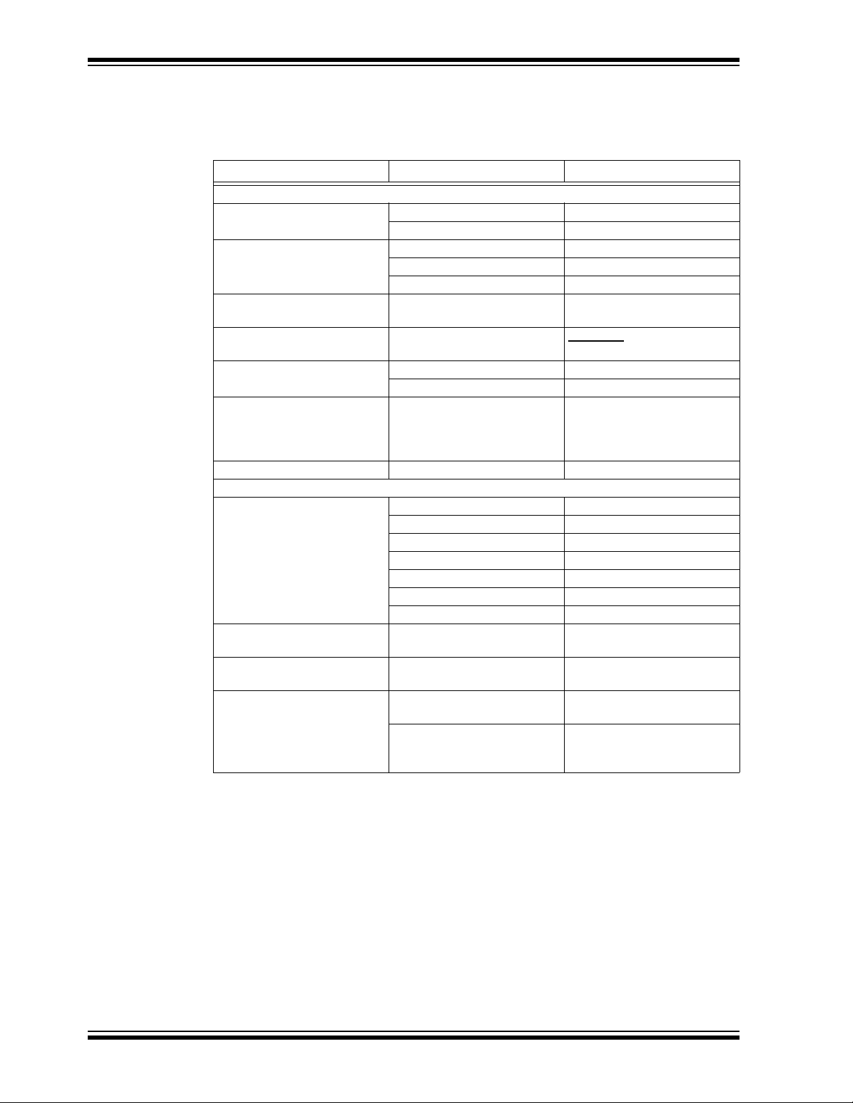
CONVENTIONS USED IN THIS GUIDE
This manual uses the following documentation conventions:
DOCUMENTATION CONVENTIONS
Description Represents Examples
Arial font:
Italic characters Referenced books MPLAB
Emphasized text ...is the only compiler...
Initial caps A window the Output window
A dialog the Settings dialog
A menu selection select Enable Programmer
Quotes A field name in a window or
dialog
Underlined, italic text with
right angle bracket
Bold characters A dialog button Click OK
N‘Rnnnn A number in verilog format,
Text in angle brackets < > A key on the keyboard Press <Enter>, <F1>
Courier New font:
Plain Courier New Sample source code #define START
Italic Courier New A variable argument file.o, where file can be
Square brackets [ ] Optional arguments mcc18 [options] file
Ellipses... Replaces repeated text var_name [,
A menu path File>Save
A tab Click the Power tab
where N is the total number of
digits, R is the radix and n is a
digit.
Filenames autoexec.bat
File paths c:\mcc18\h
Keywords _asm, _endasm, static
Command-line options -Opa+, -Opa-
Bit values 0, 1
Constants 0xFF, ‘A’
Represents code supplied by
user
“Save project before build”
4‘b0010, 2‘hF1
any valid filename
[options]
var_name...]
void main (void)
{ ...
}
®
IDE User’s Guide
DS50002414A-page 6 2015 Microchip Technology Inc.
Page 7

RECOMMENDED READING
This user's guide describes how to use the MCP25625 PICtail Plus Daughter Board.
The following Microchip documents are available and recommended as supplemental
reference resources:
• MCP25625 Data Sheet – “CAN Controller with Integrated Transceiver”
(DS20005282)
This data sheet provides detailed information regarding the MCP25625 Product Family.
• Explorer 16 User’s Guide –“Explorer 16 Development Board User’s Guide”
(DS50001589)
This user’s guide provides detailed information regarding the Explorer 16 Development
Board and its functionality.
•PICkit™ Serial Analyzer User’s Guide – “PICkit™ Serial Analyzer User’s
Guide” (DS51647)
This user’s guide provides detailed information regarding PICkit Serial Analyzer
functionality.
THE MICROCHIP WEB SITE
Microchip provides online support via our web site at www.microchip.com. This web
site is used as a means to make files and information easily available to customers.
Accessible by using your favorite Internet browser, the web site contains the following
information:
• Product Support – Data sheets and errata, application notes and sample
programs, design resources, user’s guides and hardware support documents,
latest software releases and archived software
• General Technical Support – Frequently Asked Questions (FAQs), technical
support requests, online discussion groups, Microchip consultant program
member listing
• Business of Microchip – Product selector and ordering guides, latest Microchip
press releases, listing of seminars and events, listings of Microchip sales offices,
distributors and factory representatives
Preface
CUSTOMER SUPPORT
Users of Microchip products can receive assistance through several channels:
• Distributor or Representative
• Local Sales Office
• Field Application Engineer (FAE)
• Technical Support
• Development Systems Information Line
Customers should contact their distributor, representative or field application engineer
(FAE) for support. Local sales offices are also available to help customers.
Technical support is available through the web site at:
http://www.microchip.com/support.
2015 Microchip Technology Inc. DS50002414A-page 7
Page 8

MCP25625 PICtail™ Plus Daughter Board User’s Guide
DOCUMENT REVISION HISTORY
Revision A (October 2015)
• Initial release of this document.
DS50002414A-page 8 2015 Microchip Technology Inc.
Page 9

MCP25625 PICTAIL™ PLUS
DAUGHTER BOARD
USER’S GUIDE
Chapter 1. Product Overview
1.1 OVERVIEW
This chapter provides an overview of the MCP25625 PICtail Plus Daughter Board and
covers the following topics:
•Overview
• What is the MCP25625 PICtail Plus Daughter Board?
• What the MCP25625 PICtail Plus Daughter Board kit includes.
1.2 WHAT IS THE MCP25625 PICTAIL PLUS DAUGHTER BOARD?
The MCP25625 PICtail Plus Daughter Board is a simple Controller Area Network
(CAN) board designed to be used with boards containing the PICtail Plus connector.
The board also has the PICkit Serial connector for interfacing to the PICkit Serial
Analyzer tool.
The single-chip solution CAN node consists of the MCP25625 CAN Controller with
Integrated Transceiver. The PICkit Plus and PICkit Serial connectors allow the board
to be interfaced to a variety of PIC
CAN node.
The board also contains headers or test points for most of the MCP25625 pins to allow
the external functions to be monitored/evaluated. Additionally, there are multiple external components and jumper configurations for added flexibility.
®
microcontrollers so that the user can develop a
FIGURE 1-1: MCP25625 PICTAIL™ PLUS DAUGHTER BOARD
1.3 WHAT THE MCP25625 PICTAIL PLUS DAUGHTER BOARD KIT INCLUDES
The MCP25625 PICtail Plus Daughter Board kit includes:
• MCP25625 PICtail Plus Daughter Board (02-10350)
• Information Sheet
2015 Microchip Technology Inc. DS50002414A-page 9
Page 10

MCP25625 PICtail™ Plus Daughter Board User’s Guide
NOTES:
DS50002414A-page 10 2015 Microchip Technology Inc.
Page 11

Chapter 2. Installation and Operation
2.1 HARDWARE OVERVIEW
The MCP25625 PICtail Plus Daughter Board can be connected to either a PIC microcontroller or a development board with the PICkit Plus connector or the PICkit Serial
connector. Figure 2-1 below shows the connections to the Explorer 16 Development
Board (DM240001).
2.2 JUMPER SETTINGS
Ta bl e 2 -1 briefly describes the functions of all the board's jumpers.
TABLE 2-1: JUMPER DESCRIPTIONS
Index Description
JP1
JP2
JP3
JP4
JP5
JP6
JP7
Note 1: Jumpers JP3, JP4, JP5, JP6 and JP7 are not populated, however, they are
• Drives the STBY pin of the transceiver to GND manually or via the
Explorer 16 demo board when used as PICTail™ daughter board
(plugged into the Explorer 16).
• Short-circuit pins 1 and 2 (top and middle) to connect to GND, or pins 2
and 3 (middle and bottom) to connect to the Explorer 16.
Default configuration: pins 1 and 2 (top and middle) short-circuited.
• Powers-up the CAN Controller with 5V or 3.3V. It also feeds the VIO of
the transceiver; this voltage is determined by the MCU that the user
implements (5V or 3.3V).
• Short-circuit pins 1 and 2 (left-hand side) to select 5V, or pins 2 and 3
(right-hand side) to select 3.3V.
Default configuration selects 5V operation mode.
(1)
When disconnected, separates the RXD of the transceiver from the RXCAN of the
controller.
(1)
When disconnected, separates the TXD of the transceiver from the TXCAN of the
controller.
(1)
When connected, enables access to the 9V supply from the Explorer 16.
(1)
When connected, implements a capacitor with the jumper JP7 enabled 120Ω
termination resistor.
(1)
When connected, implements the 120Ω termination resistor.
short-circuited on the bottom layer (back) of the board. The traces can be cut in
order to disconnect them.
MCP25625 PICTAIL™ PLUS
DAUGHTER BOARD
USER’S GUIDE
2015 Microchip Technology Inc. DS50002414A-page 11
Page 12

MCP25625 PICtail™ Plus Daughter Board User’s Guide
Legend:
= pins connected with jumper header
= jumper short circuited on bottom layer (back side) of the board
MCP25625 PICtail™ Plus
Explorer 16 Board (DM240001)
PICkit™ Serial Header
Figure 2-1 indicates the default settings for the jumpers.
FIGURE 2-1: DEFAULT JUMPER CONFIGURATIONS
2.3 CONNECTING THE BOARD
FIGURE 2-2: HARDWARE OVERVIEW
DS50002414A-page 12 2015 Microchip Technology Inc.
Page 13

2.4 OPERATION
The user can write firmware for the MCP25625 PICtail Plus Daughter Board in order
to create a custom CAN node. Check the Explorer 16 and PICkit Serial Analyzer web
pages for the latest firmware and/or software supporting the MCP25625 or general
SPI interfaces.
2015 Microchip Technology Inc. DS50002414A-page 13
Page 14

MCP25625 PICtail™ Plus Daughter Board User’s Guide
NOTES:
DS50002414A-page 14 2015 Microchip Technology Inc.
Page 15

Appendix A. Schematic and Layouts
A.1 INTRODUCTION
This appendix contains the following schematics and layouts for the MCP25625 PICtail
Plus Daughter Board:
• Board – Schematic
• Board – Top Silk
• Board – Top Copper and Silk
• Board – Top Copper
• Board – Bottom Copper
• Board – Bottom Copper and Silk
• Board – Bottom Silk
MCP25625 PICTAIL™ PLUS
DAUGHTER BOARD
USER’S GUIDE
2015 Microchip Technology Inc. DS50002414A-page 15
Page 16

RF6/SCK
RF8/MOSI
RB5/AN5/NCS
RF7/MISO
RE8/NINT
VDD
GND
VDD
GND
GND
GND
GND
GNDGND
Optional ESD protection
GND
GND
GND GND
GND
GND
RF6/SCK
RF7/MISO
RF8/MOSI
RB5/AN5/NCS
RE8/NINT
GND
GND
GND
GND
TXCAN/TXD
TXCAN/TXD
RXCAN/RXD
RXCAN/RXD
CLKOUT
CLKOUT
RX1BF
RX0BF
RX1BF
RX0BF
RE8/NINT
RB5/AN5/NCS
RF7/MISO
RF6/SCK
RF8/MOSI
GND
+3.3V +5 V +9V+3.3V+5V+9V
+3.3V +5 V +9V+3.3V+5V+9V
+3.3V +3.3V
VDD
+5V
+3.3V
VDD
+9V
+5V
GND
VDD
VDD VDD
GND
GND GND
STBY
RB6/STBY
STBY
GND
RB6/STBY
2
1
3
4
J4
GND
GND
VDD
NTX2RTS
NTX1RTS
NTX0RTS
NTX0RTS
NTX1RTS
NTX2RTS
GND
GND
GND
10 uF
6.3V
0805
C14
10 uF
6.3V
0805
C1
0.1 uF
25V
0805
C2
0.1 uF
25V
0805
C7
0.1 uF
25V
0805
C11
0.1 uF
25V
0805
C12
0.1 uF
25V
0805
C13
4700 pF
100V
0805
C9
47 pF
200V
0805
C8
47 pF
200V
0805
C10
470R
0805
1%
R4
470R
0805
1%
R5
10k
0805
1%
R6
10k
0805
1%
R1
10k
0805
1%
R2
10k
0805
1%
R3
60.4R
1206
1%
R8
60.4R
1206
1%
R9
123456789
10
HDR -2.54 M ale 1x10
J1
1
2
3
4
5
6
HDR -2.54 M ale 1x6
J3
123
HDR-2.54 Male 1x3
JP1
123
HDR-2.54 Male 1x3
JP2
12
JP7
12
HDR-2.54 Male 1x2
JP5
RST
SW1
1
GND
TP4
1
GND
TP5
1
GND
TP6
1
GND
TP7
1
VDD
1
+3.3V
1
+5V
2
3
1
20 MHz
X1
1 2
3
21 22
23 24
25 26
27 28
29 30
33 34
35 36
37 38
39 40
41 42
43 44
45 46
47 48
49 50
51 52
53 54
55 56
57 58
59 60
61 62
65 66
67 68
69 70
71 72
73 74
75 76
77 78
79 80
81 82
83 84
85 86
87 88
89 90
91 92
93 94
95 96
97 98
99 100
101 102
103 104
105 106
107 108
109 110
111 112
113 114
115 116
117 118
119 120
4
5 6
7 8
9 10
11 12
13 14
15 16
17 18
19 20
EDGE 80P Male
J2
1
2
3
4
5
6
7
8
9 DE-9 Male
J5
GND
12
JP3
12
JP4
12
JP6
RED
TXD
RED
RXD
RED
INT
470R
0805
1%
R7
1
2
3
MM BZ 27V CL T 1G
D3
1
2
3
MMBZ27VCLT 1G
D4
0.1 uF
25V
0805
C15
GND
SJ61A11
PAD1
SJ61A11
PAD2
SJ61A11
PAD3
SJ61A11
PAD4
1
CANH
1
CANL
Shunt 2.54 mm 1x2 Handle
JP1_shunt
Shunt 2.54 mm 1x2 Handle
JP2_shunt
CS
1
RESET
2
VDD
3
TxCAN
4
RxCAN
5
CLKOUT
6
Tx0RTS
7
Tx1RTS
8
Tx2RTS
9
RxD
10
VIO
11
CANL
12
CANH
13
NC
14
STBY
15
TxD
16
NC
17
VSS
18
VDDA
19
OSC2
20
OSC1
21
GND
22
Rx1BF
23
Rx0BF
24
INT
25
SCK
26
SI
27
SO
28
EP
29
MCP25625
U2
DS50002414A-page 16 2015 Microchip Technology Inc.
MCP25625 PICtail™ Plus Daughter Board User’s Guide
A.2 BOARD – SCHEMATIC
Page 17

A.3 BOARD – TOP SILK
A.4 BOARD – TOP COPPER AND SILK
2015 Microchip Technology Inc. DS50002414A-page 17
Page 18

MCP25625 PICtail™ Plus Daughter Board User’s Guide
A.5 BOARD – TOP COPPER
A.6 BOARD – BOTTOM COPPER
DS50002414A-page 18 2015 Microchip Technology Inc.
Page 19

A.7 BOARD – BOTTOM COPPER AND SILK
A.8 BOARD – BOTTOM SILK
2015 Microchip Technology Inc. DS50002414A-page 19
Page 20

MCP25625 PICtail™ Plus Daughter Board User’s Guide
NOTES:
DS50002414A-page 20 2015 Microchip Technology Inc.
Page 21

MCP25625 PICTAIL™ PLUS
DAUGHTER BOARD
USER’S GUIDE
Appendix B. Bill Of Materials (BOM)
TABLE B-1: BILL OF MATERIALS
Qty. Reference Description Manufacturer Part Number
9 +3.3V, +5V,
CANH, CANL,
TP4, TP5, TP6,
TP7, VDD
2 C1, C14 Cap. ceramic 10 µF 6.3V 10% X5R SMD 0805 KEMET
6 C2, C7, C11,
C12, C13, C15
2 C8, C10 Cap. ceramic 47 pF 200V 5% C0G, NP0 SMD
1 C9 Cap. ceramic 4700 pF 100V 10% X7R SMD
2 D3, D4 Diode TVS MMBZ27VCLT1G 22V 40W
3 INT, RXD, TXD Diode LED red 1.7V 20 mA 11.7mcd
1 J1 Conn. header-2.54 male 1x10 Gold 5.84MH TH
1 J3 Conn. header-2.54 male 1x6 Tin 5.84MH TH
1 J5 Conn. DSUB DE-9 male TH R/A FCI 10090097-P094VLF
2 JP1, JP2 Conn. header-2.54 male 1x3 Tin 5.84MH TH
2 JP1_shunt,
JP2_shunt
5 JP3, JP4, JP5,
JP6, JP7
4PAD1, PAD2,
PAD 3, PA D4
1 PCB RoHS Compliant Bare PCB,
4 R1, R2, R3, R6 Res. TKF 10 kΩ 1% 1/8W SMD 0805 Panasonic
3 R4, R5, R7 Res. TKF 470R 1% 1/16W SMD 0805 Stackpole
2 R8, R9 Res. TKF 60.4R 1% 1/4W SMD 1206 Yageo Corporation RC1206FR-0760R4L
1 SW1 Switch Tact. SPST 32V 50 mA KSR231GLFS
1 U2 MCHP Interface CAN MCP25625-E/ML QFN-28 Microchip
1 X1 Resonator 20M Hz 0.1% SMD CSTCE Murata Electronics CSTCE20M0V13L99-R0
Note: The components listed in this Bill of Materials are representative of the PCB assembly. The
released BOM used in manufacturing uses all RoHS-compliant components.
Conn. TP Loop Tin SMD Harwin Plc. S1751-46R
®
Cap. ceramic 0.1 µF 25V 10% X7R SMD 0805 Murata Electronics
KEMET C0805C470J2GACTU
0805
0805
SOT-23-3
Diffuse SMD 0805
vert.
vert.
vert.
Mech. HW Jumper 2.54 mm 1x2 Handle Gold TE Connectivity 881545-2
Conn. header-2.54 male 1x2 Tin 6.10MH TH
vert.
Mech. HW Rubber pad Cylindrical D7.9 H5.3
black
MCP25625 PICtail™ Plus Daughter Board
SMD
TDK Corporation C2012X7R2A472K
ON Semiconductor
CML Technologies
GmbH & Co. KG
Samtec, Inc. TSW-110-07-L-S
Sullins Connector
Solutions
Samtec, Inc. TSW-103-07-T-S
®
Molex
3M SJ61A11
Microchip
Technology Inc.
Electronics, Inc.
C&K Components KSR231GLFS
Technology Inc.
®
– ECG ERJ-6ENF1002V
C0805C106K9PACTU
®
GRM21BR71E104KA01L
®
MMBZ27VCLT1G
7012X1
PEC06SAAN
0022284020
104-10350
RMCF0805FT470R
MCP25625T-E/SO
2015 Microchip Technology Inc. DS50002414A-page 21
Page 22

Worldwide Sales and Service
AMERICAS
Corporate Office
2355 West Chandler Blvd.
Chandler, AZ 85224-6199
Tel: 480-792-7200
Fax: 480-792-7277
Technical Support:
http://www.microchip.com/
support
Web Address:
www.microchip.com
Atlanta
Duluth, GA
Tel: 678-957-9614
Fax: 678-957-1455
Austin, TX
Tel: 512-257-3370
Boston
Westborough, MA
Tel: 774-760-0087
Fax: 774-760-0088
Chicago
Itasca, IL
Tel: 630-285-0071
Fax: 630-285-0075
Cleveland
Independence, OH
Tel: 216-447-0464
Fax: 216-447-0643
Dallas
Addison, TX
Tel: 972-818-7423
Fax: 972-818-2924
Detroit
Novi, MI
Tel: 248-848-4000
Houston, TX
Tel: 281-894-5983
Indianapolis
Noblesville, IN
Tel: 317-773-8323
Fax: 317-773-5453
Los Angeles
Mission Viejo, CA
Tel: 949-462-9523
Fax: 949-462-9608
New York, NY
Tel: 631-435-6000
San Jose, CA
Tel: 408-735-9110
Canada - Toronto
Tel: 905-673-0699
Fax: 905-673-6509
ASIA/PACIFIC
Asia Pacific Office
Suites 3707-14, 37th Floor
Tower 6, The Gateway
Harbour City, Kowloon
Hong Kong
Tel: 852-2943-5100
Fax: 852-2401-3431
Australia - Sydney
Tel: 61-2-9868-6733
Fax: 61-2-9868-6755
China - Beijing
Tel: 86-10-8569-7000
Fax: 86-10-8528-2104
China - Chengdu
Tel: 86-28-8665-5511
Fax: 86-28-8665-7889
China - Chongqing
Tel: 86-23-8980-9588
Fax: 86-23-8980-9500
China - Dongguan
Tel: 86-769-8702-9880
China - Hangzhou
Tel: 86-571-8792-8115
Fax: 86-571-8792-8116
China - Hong Kong SAR
Tel: 852-2943-5100
Fax: 852-2401-3431
China - Nanjing
Tel: 86-25-8473-2460
Fax: 86-25-8473-2470
China - Qingdao
Tel: 86-532-8502-7355
Fax: 86-532-8502-7205
China - Shanghai
Tel: 86-21-5407-5533
Fax: 86-21-5407-5066
China - Shenyang
Tel: 86-24-2334-2829
Fax: 86-24-2334-2393
China - Shenzhen
Tel: 86-755-8864-2200
Fax: 86-755-8203-1760
China - Wuhan
Tel: 86-27-5980-5300
Fax: 86-27-5980-5118
China - Xian
Tel: 86-29-8833-7252
Fax: 86-29-8833-7256
ASIA/PACIFIC
China - Xiamen
Tel: 86-592-2388138
Fax: 86-592-2388130
China - Zhuhai
Tel: 86-756-3210040
Fax: 86-756-3210049
India - Bangalore
Tel: 91-80-3090-4444
Fax: 91-80-3090-4123
India - New Delhi
Tel: 91-11-4160-8631
Fax: 91-11-4160-8632
India - Pune
Tel: 91-20-3019-1500
Japan - Osaka
Tel: 81-6-6152-7160
Fax: 81-6-6152-9310
Japan - Tokyo
Tel: 81-3-6880- 3770
Fax: 81-3-6880-3771
Korea - Daegu
Tel: 82-53-744-4301
Fax: 82-53-744-4302
Korea - Seoul
Tel: 82-2-554-7200
Fax: 82-2-558-5932 or
82-2-558-5934
Malaysia - Kuala Lumpur
Tel: 60-3-6201-9857
Fax: 60-3-6201-9859
Malaysia - Penang
Tel: 60-4-227-8870
Fax: 60-4-227-4068
Philippines - Manila
Tel: 63-2-634-9065
Fax: 63-2-634-9069
Singapore
Tel: 65-6334-8870
Fax: 65-6334-8850
Taiwan - Hsin Chu
Tel: 886-3-5778-366
Fax: 886-3-5770-955
Taiwan - Kaohsiung
Tel: 886-7-213-7828
Taiwan - Taipei
Tel: 886-2-2508-8600
Fax: 886-2-2508-0102
Thailand - Bangkok
Tel: 66-2-694-1351
Fax: 66-2-694-1350
EUROPE
Austria - Wels
Tel: 43-7242-2244-39
Fax: 43-7242-2244-393
Denmark - Copenhagen
Tel: 45-4450-2828
Fax: 45-4485-2829
France - Paris
Tel: 33-1-69-53-63-20
Fax: 33-1-69-30-90-79
Germany - Dusseldorf
Tel: 49-2129-3766400
Germany - Karlsruhe
Tel: 49-721-625370
Germany - Munich
Tel: 49-89-627-144-0
Fax: 49-89-627-144-44
Italy - Milan
Tel: 39-0331-742611
Fax: 39-0331-466781
Italy - Venice
Tel: 39-049-7625286
Netherlands - Drunen
Tel: 31-416-690399
Fax: 31-416-690340
Poland - Warsaw
Tel: 48-22-3325737
Spain - Madrid
Tel: 34-91-708-08-90
Fax: 34-91-708-08-91
Sweden - Stockholm
Tel: 46-8-5090-4654
UK - Wokingham
Tel: 44-118-921-5800
Fax: 44-118-921-5820
07/14/15
DS50002414A-page 22 2015 Microchip Technology Inc.
Page 23

Mouser Electronics
Authorized Distributor
Click to View Pricing, Inventory, Delivery & Lifecycle Information:
Microchip:
ADM00617
 Loading...