

Page 1
PICDEM™ PIC18 Explorer
Demonstration Board
User’s Guide
© 2008 Microchip Technology Inc. DS51721B
Page 2

Note the following details of the code protection feature on Microchip devices:
• Microchip products meet the specification contained in their particular Microchip Data Sheet.
• Microchip believes that its family of products is one of the most secure families of its kind on the market today, when used in the
intended manner and under normal conditions.
• There are dishonest and possibly illegal methods used to breach the code protection feature. All of these methods, to our
knowledge, require using the Microchip products in a manner outside the operating specifications contained in Microchip’s Data
Sheets. Most likely, the person doing so is engaged in theft of intellectual property.
• Microchip is willing to work with the customer who is concerned about the integrity of their code.
• Neither Microchip nor any other semiconductor manufacturer can guarantee the security of their code. Code protection does not
mean that we are guaranteeing the product as “unbreakable.”
Code protection is constantly evolving. We at Microchip are committed to continuously improving the code protection features of our
products. Attempts to break Microchip’s code protection feature may be a violation of the Digital Millennium Copyright Act. If such acts
allow unauthorized access to your software or other copyrighted work, you may have a right to sue for relief under that Act.
Information contained in this publication regarding device
applications and t he lik e is provided only for your convenience
and may be su perseded by upda t es . It is y our responsibility to
ensure that your application meets with your specifications.
MICROCHIP MAKES NO REPRESENTATIONS OR
WARRANTIES OF ANY KIND WHETHER EXPRESS OR
IMPLIED, WRITTEN OR ORAL, STATUTORY OR
OTHERWISE, RELATED TO THE INFORMATION,
INCLUDING BUT NOT LIMITED TO ITS CONDITION,
QUALITY, PERFORMANCE, MERCHANTABILITY OR
FITNESS FOR PURPOSE. Microchip disclaims all liability
arising from this information and its use. Use of Microchip
devices in life supp ort and/or safety ap plications is entir ely at
the buyer’s risk, and the buyer agrees to defend, indemnify and
hold harmless M icrochip from any and all dama ges, claims,
suits, or expenses re sulting from such use. No licens es are
conveyed, implicitly or otherwise, under any Microchip
intellectual property rights.
Trademarks
The Microchip name and logo, the Microchip logo, Accuron,
dsPIC, K
EELOQ, KEELOQ logo, MPLAB, PIC, PICmicro,
PICSTART, PRO MA TE, rfPIC and SmartShunt are registered
trademarks of Microchip Technology Incorporated in the
U.S.A. and other countries.
FilterLab, Linear Active Thermistor, MXDEV, MXLAB,
SEEVAL, SmartSensor and The Embedded Control Solutions
Company are registered trademarks of Microchip Technology
Incorporated in the U.S.A.
Analog-for-the-Digital Age, Application Maestro, CodeGuard,
dsPICDEM, dsPICDEM.net, dsPICworks, dsSPEAK, ECAN,
ECONOMONITOR, FanSense, In-Circuit Serial
Programmin g , IC SP, ICEPIC, Mindi, MiW i , MPASM, MPLAB
Certified logo, MPLIB, MPLINK, mTouch, PICkit, PICDEM,
PICDEM.net, PICtail, PIC
32
logo, PowerCal, PowerInfo,
PowerMate, PowerT ool, REAL ICE, rfLAB, Select Mode, Total
Endurance, UNI/O, WiperLock and ZENA are trademarks of
Microchip Technology Incorporated in the U.S.A. and other
countries.
SQTP is a service mark of Microchip Technology Incorporated
in the U.S.A.
All other trademarks mentioned herein are property of their
respective companies.
© 2008, Microchip Technology Incorporated, Printed in the
U.S.A., All Rights Reserved.
Printed on recycled paper.
Microchip received ISO/TS-16949:2002 certification for its worldwide
headquarters, design and wafer fabrication facilities in Chandler and
Tempe, Arizona; Gresham, Oregon and design centers in California
and India. The Company’s quality system processes and procedures
are for its PIC
devices, Serial EEPROMs, microperipherals, nonvolatile memory and
analog products. In addition, Microchip’s quality system for the design
and manufacture of development systems is ISO 9001:2000 certified.
®
MCUs and dsPIC® DSCs, KEELOQ
®
code hopping
DS51721B-page ii © 2008 Microchip Technology Inc.
Page 3

PICDEM™ PIC18 EXPLORER
DEMONSTRATION BOARD
USER’S GUIDE
Table of Contents
Preface ...........................................................................................................................1
Chapter 1. Introduction
1.1 Introduction .....................................................................................................5
1.2 Developm e nt Ki t C o n te n ts ......... ........................................ .. .. ......................... 5
1.3 PICDEM™ P IC1 8 E xp l orer Demonstr a tio n B o ard ..... ........................... .. .. ..... 6
1.4 Sample Devices .... ... .. .................................................................................... 7
1.5 Sample Pro g ram s ................................................. .......................................... 7
Chapter 2. Getting Started
2.1 Board as Stand-Alone Device ...................... ...................... .. ...................... ....9
2.2 Board with In-Circuit Debugger ....................................................................11
2.3 Board with PIM Attached Devices ................................................................12
2.4 Programming the Microcontrollers ............................................................... 16
2.5 Connecting to Host PC for RS-232 Communication ....................................19
Chapter 3. PICDEM™ PIC18 Explorer Demonstration Board Tutorial Program
3.1 Tutorial Pr o g ra m O p e ra tion ... .. ..................................................... .. .. ............ 23
3.2 Source Code and Data Sheets .............................. .......................... .. ...........25
Appendix A. Hardware Details
A.1 Hardware E le ments . .. .......................... .. ... ................................................... 27
A.2 Board Layo u t an d S c h e ma tic s ..................................................................... 30
Worldwide Sales and Service ....................................................................................34
© 2008 Microchip Technology Inc. DS51721B-page iii
Page 4

PICDEM™ PIC18 Explorer Demonstration Board User’s Guide
NOTES:
DS51721B-page iv © 2008 Microchip Technology Inc.
Page 5
PICDEM™ PIC18 EXPLORER
DEMONSTRATION BOARD
USER’S GUIDE
Preface
NOTICE TO CUSTOMERS
All documentation becomes dated, and this manual is no exception. Microchip tools and
documentation are constantly evolving to meet customer needs, so some actual dialogs
and/or tool descriptions may differ from those in this document. Please refer to our web site
(www.microchip.com) to obtain the latest documentation available.
Documents are identified with a “DS” number. This number is located on the bottom of each
page, in front of the p age number. The numbering convention for the DS number is
“DSXXXXXA”, where “XXXXX” is the document number and “A” is the revision level of the
document.
For the most up-to-date information on development tools, see the MPLAB
Select the Help menu, and then Topics to open a list of available on-line help files.
®
IDE on-line help.
INTRODUCTION
This chapter contains general information that will be useful to know before using the
PICDEM™ PIC18 Explorer Demonstration Board. Items discussed in this chapter
include:
• Document Layout
• Conventions Used in This Guide
• Warranty Registration
• Recommended Reading
• The Microchip Web Site
• Development Systems Customer Change Notification Service
• Customer Support
• Document Revision History
DOCUMENT LAYOUT
This document describes how to use the PICDEM PIC18 Explorer Demonstration
Board as a development tool to emulate and debug firmware on a target board. The
manual layout is as follows:
• Chapter 1. “Introduction” – Overview of the development board and kit
• Chapter 2. “Getting Started” – Description of the different ways to use the board
• Chapter 3. “PICDEM™ PIC18 Explorer Demonstration Board Tutorial Program”
– Explanation of t he tu to ri al prep r ogra mme d o n the sa mpl e d evice s
• Appendix A. “Hardware Details” – Description of the board’s hardware
elements, including layout and schematic drawings
© 2008 Microchip Technology Inc. DS51721B-page 1
Page 6
PICDEM™ PIC18 Explorer Demonstration Board User’s Guide
CONVENTIONS USED IN THIS GUIDE
This manual uses the following docum entat io n conven tion s:
DOCUMENTATION CONVENTIONS
Description Represents Examples
Arial font:
Italic chara c ters Referenced books MPLAB
Emphasized text ...is the only compiler...
Initial caps A window the Output window
A dialog the Settings dialog
A menu selection select Enable Programmer
Quotes A field name in a window or
dialog
Underlined, italic text with
right angle bracket
Bold characters A dialog button Click OK
N‘Rnnnn A number in verilog format,
Text in angle brac kets < > A key on the keyboard Press <Enter>, <F1>
Courier New font:
Plain Courier New Sample source code #define START
Italic Courier New A variable argument file.o, where file can be
Square brackets [ ] Optional arguments mcc18 [options] file
Curly brackets and pipe
character: { | }
Ellipses... Replaces r epeated text var_name [,
A menu path File>Save
A tab Click the Power tab
A button on board Press RB0.
where N is the tota l number of
digits, R is th e radi x and n is a
digit.
Filenames autoexec.bat
File paths c:\mcc18\h
Keywords _asm, _endasm, static
Command-line options -Opa+, -Opa-
Bit values 0, 1
Constants 0xFF, ‘A’
Choice of mut ually exclus ive
arguments; an OR selection
Represents code supplied by
user
“Save project before build”
4‘b0010, 2‘hF1
any valid filename
[options]
errorlevel {0|1}
var_name...]
void main (void)
{ ...
}
®
IDE User’s Guide
DS51721B-page 2 © 2008 Microchip Technology Inc.
Page 7

WARRANTY REGISTRATION
Please complete the enclosed Warranty Registration Card and mail it promptly.
Sending in the Warranty Registration Card entitles users to receive new product
updates. Interim software releases are available at the Microchip web site.
RECOMMENDED READING
This user’s guide describes how to use the PICDEM PIC18 Explorer Demonstration
Board. Other useful documents are listed below.
• On the board kit’s CD-ROM:
- Readme file
- Other reference documents
• Other documents, available at http://microchip.com
- “MPLAB
- “PICkit™ 2 Programmer/Debugger User’s Guide” (DS51553)
- “Microchip Development Systems Ordering Guide” (DS 30 177 )
®
ICD 2 In-Circuit Debugger User’s Guide” (DS51331)
THE MICROCHIP WEB SITE
Microchip provides online support via our web site at http://microchip.com. This web
site is used as a means to make files and information easily available to customers.
The web site contains the following information:
• Product Support – Data sheets and errata, application notes and sample
programs, design resources, user’s guides and hardware support documents,
latest software releases and archived software
• General Technical Support – Frequently Asked Questions (FAQs), technical
support requests, online discussion groups, Microchip consultant program
member listing
• Business of Microchip – Product selector and ordering guides, latest Microchip
press releases, listing of seminars and events, listings of Microchip sales offices,
distributors and factory representatives
Preface
:
© 2008 Microchip Technology Inc. DS51721B-page 3
Page 8

PICDEM™ PIC18 Explorer Demonstration Board User’s Guide
DEVELOPMENT SYSTEMS CUSTOMER CHANGE NOTIFICATION SERVICE
Microchip’s customer notification service helps keep customers current on Microchip
products. Subscribers will receive e-mail notification whenever there are changes,
updates, revisions or errata related to a specified product family or development tool of
interest.
To register, access the Microchip web site at http://microchip.com
Change Notification and follow the registration instructions.
The Development Systems product group categories are:
• Compilers – The latest information on Microchip C compilers and other language
tools. These include the MPLAB C18 and MPLAB C30 C compilers; MPASM™
and MPLAB ASM30 assemblers; MPLINK™ and MPLAB LINK30 object linkers;
and MPLIB™ and MPLAB LIB30 object librarians.
• Emulators – The latest information on Microchip in-circuit emulators.This
includes the MPLAB ICE 2000 and MPLAB ICE 4000.
• In-Circuit Debuggers – The latest information on the Microchip in-circuit
debugger, MPLAB ICD 2.
• MPLAB
Integrated Development Environment for development systems tools. This list is
focused on the MPLAB IDE, MPLAB SIM simulator, MPLAB IDE project manager
and general editing and debugging features.
• Programmers – The latest information on Microchip programmers. These include
the MPLAB PM3 and PRO MATE
Plus and PICkit™ 1 development programmers.
®
IDE – The latest information on Microchip MPLAB IDE, the Windows®
®
II device programmers and the PICSTART®
, click on Custome r
CUSTOMER SUPPORT
Users of Microchip products can receive assistance through several channels:
• Distributor or Representative
• Local Sales Office
• Field Application Engineer (FAE)
• Technical Support
Customers should contact their distributor, representative or field application engineer
(FAE) for support. Local sales offices are also available to help customers. A listing of
sales offices and locations is included in the back of this document.
Technical support is available through the web site at: http://support.microchip.com
DOCUMENT REVISION HISTORY
Revision A (March 2008)
• Initial release of this document.
Revision B (May 2008)
• Name and title change.
.
DS51721B-page 4 © 2008 Microchip Technology Inc.
Page 9

Chapter 1. Introduction
1.1 INTRODUCTION
The PICDEM™ PIC18 Explorer Demonstration Board is the latest demonstration board
for evaluating Microchip Technology’s PIC18FXXXX and PIC18FXXJXX families of
devices.
The board can be used as a stand-alone device or with an in-circuit debugger, such as
the MPLAB
Sample programs are provided to demonstrate the unique features of the supported
devices. Free software development tools are available for application development
and debugging.
1.2 DEVELOPMENT KI T CON TEN TS
The PICDEM PIC18 Explorer Demonstration Board Kit comes with the following:
• PICDEM™ PIC18 Explorer Demonstration Board (Figure 1-1)
• Board-mounted PIC18F8722 and an alternate PIC18F87J11 mounted on a
Plug-In Module (PIM)
• CD-ROM that contains:
- Sample programs, source code and Hex files
- “PICDEM™ PIC18 Explorer Demonstration Board User’s Guide”
- Other referenced documents
If you are missing any part of the kit, contact your nearest Microchip sales office listed
in the back of this publication.
The MPLAB
software tool set for application development and debugging. Compilers and other
board-compatible software and hardware tools can be purchased.
To download the MPLAB IDE software and documentation, or get information on the
other tools, visit http://microchip.com
®
ICD 2, and host PC.
®
Integrated Development Environment (IDE) is a free, integrated
PICDEM™ PIC18 EXPLORER
DEMONSTRATION BOARD
USER’S GUIDE
.
© 2008 Microchip Technology Inc. DS51721B-page 5
Page 10

PICDEM™ PIC18 Explorer Demonstration Board User’s Guide
1.3 PICDEM™ PIC18 EXPLORER DEMONSTRATION BOARD
The PICDEM PIC18 Explorer Demonstration Board has the following hardware
features with each feature’s number corresponding to the number in Figure 1-1 that
shows the feature’s location on the board:
1. PIC18F8722 microcontroller – The sample, primary microcontroller mounted on
the board.
2. Male header pins for connecting Plug-In Modules (PIMs). A PIM enables an
alternate PIC18 device to be connected to the board, as the primary
microcontroller.
3. In-Circuit Debugger (ICD) connector.
4. Six-pin, PICkit™ 2 connector.
5. 10 kΩ potentiometer for analog inputs.
6. Push button switch – For external Reset.
7. USB connector – For RS-232 communication.
8. PIC18LF2450 microcontroller – For converting RS-232 communication to USB
protocol for attachment of a host PC.
9. 12 MHz crystal – For the PIC18LF2450 microcontroller.
10. RS-232 DB9 socket and associated hardware – For direct connection to an
RS-232 int erface.
11. Jumper J13 for routing RS-232 communication through either the USB port or
the RS-232 socket.
12. Jumper J4 – For selecting between programming the main PIC
PIC18LF2450, used for USB to RS-232 communication.
13. Switch S4 – For designating the main microcontroller as either the
board-mounted PIC18F8722 or a PIM-mounted microcontroller.
14. LED – For power-on indication.
15. JP1 – For disconnecting the eight display LEDs.
16. Eight LEDs.
17. 32.768 kHz crystal – For Timer1 clock operation.
18. Two push button switches – For external stimulus.
19. Analog temperature sensor, MPC9701A.
20. 25LC256 SPI EEPROM.
21. JP2 – To enable/disable EEPROM.
22. JP3 – To enable/disable LCD.
23. 10 MHz crystal – For the main microcontroller.
24. PICtail™ daughter board connector socket.
25. SPI I/O expander – For LCD display, MCP23S17.
26. Prototype area – For user hardware.
27. LCD display.
28. J2 three-pin, male header – For selecting between a voltage of 3.3V or 5V.
29. J14 four-pin, male header – For use with a PIM, if required, to connect 3.3V or
5V, V
IN and ICE MCLR.
®
device or the
DS51721B-page 6 © 2008 Microchip Technology Inc.
Page 11
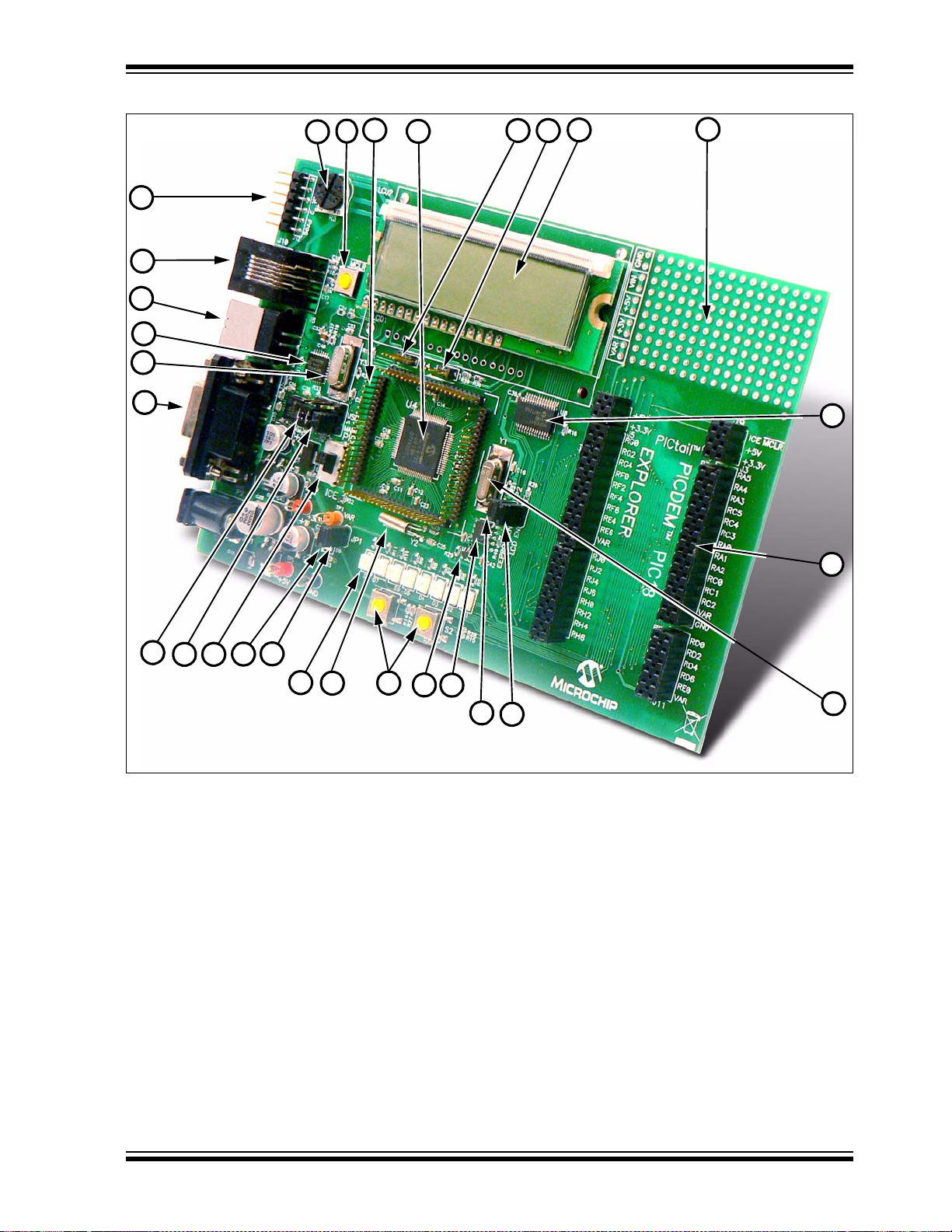
FIGURE 1-1: PICDEM™ PIC18 EXPLORER DEMONSTRATION BOARD
29
1
2
3
4
5
6
7
8
9
10
11
12
13
14 15
16
17
18
19
20
21
22
23
24
25
26
27
28
Introduction
1.4 SAMPLE DEVICES
The PICDEM PIC18 Explorer Demonstration Board comes with two sample devices
that alternately can be used as the main microcontroller:
• An 18-pin, 5V PIC microcontroller (the PIC18F8722) mounted on the board
• A 3.3V PIC18 device (PIC18F87J11) mounted on an 80-pin PIM that connects to
the demo board via an 80-pin male
1.5 SAMPLE PROGRAMS
The PICDEM PIC18 Explorer Demonstration Board Kit includes a CD-ROM with
sample demonstration programs. These programs may be used with the included
sample devices and with an In-Circuit Debugger (ICD).
Also provided on the disc is demonstration source code that includes several assembly
source code (ASM) files and one Hex compiled code file.
© 2008 Microchip Technology Inc. DS51721B-page 7
Page 12

PICDEM™ PIC18 Explorer Demonstration Board User’s Guide
NOTES:
DS51721B-page 8 © 2008 Microchip Technology Inc.
Page 13

PICDEM™ PIC18 EXPLORER
DEMONSTRATION BOARD
USER’S GUIDE
Chapter 2. Getting Started
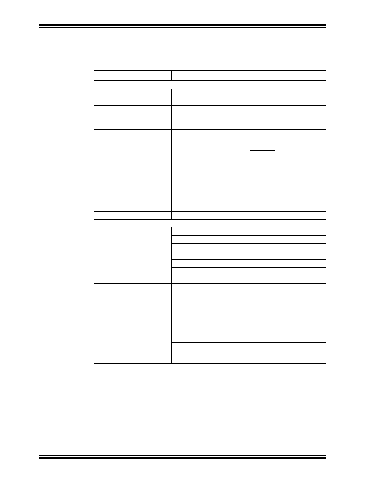
The PICDEM™ PIC18 Explorer Demonstration Board may be used in a variety of
ways. Table 2-1 lists the three primary configurations and the required equipment and
capabilities of each.
T ABLE 2-1: PICDEM™ PIC18 EXPLORER DEMONSTRATION BOARD CONFIGURATIONS
Configuration Board Connections Board Capabilities
• Access board’s full functionality
• Demonstrate sample code
Stand-alone board Power supply
• Power supply
Board with in-circuit
debugger/programmer
Board with alternate
microcontroller, attached
through a Plug-In Module
(PIM)
† PIM enables 80, 64, 44 and 28-pin devices to be used as the main microcontroller. For information on the
available PIMs, go to
• In-Circuit Debugger (ICD) that
also can be used as a
programmer
• Power supply
• ICD that also can be used as a
programmer
• PIM with mounted microcontroller
http://microchip.com.
• Display functionality with LCD or LEDs
• Connect ICD/programmer for debugging or
programming
• Connect PICtail™ daughter cards
• Access board’s full functionality
• Demonstrate sample code
• Develop and debug code
• Repr ogram micr ocontrollers
• Connect PICtail daughter cards
• Substitute PIM-mounted device as main
microcontroller
• Use 3.3V or 5V devices as main microcontroller
• Demonstrate sample code
• Develop and debug code
• Repr ogram micr ocontrollers
• Connect PICtail daughter cards
†
This chapter describes:
• How to implement each of the uses described in Table 2-1
• How to reprogram the main and RS-232 to USB microcontrollers
• How to connect the demonstration board to a host PC for RS-232 communication
2.1 BOARD AS STAND-ALONE DEVICE
In using the PICDEM PIC18 Explorer Demonstration Board as a stand-alone device,
an implementation can:
• Use the board as is, utilizing the firmware loaded on the main, PIC18F8722
microcontroller and RS-232 to USB PIC18LF2450 microcontroller
• Reprogram the main, PIC18F8722 microcontroller or the RS-232 to USB,
PIC18LF2450 microcontroller and demonstrate user programs
© 2008 Microchip Technology Inc. DS51721B-page 9
Page 14

PICDEM™ PIC18 Explorer Demonstration Board User’s Guide
PIC® MCU
S4
ICE
S4 Switch
Switch Location Switch Position
JP2
JP3
JP1
2.1.1 Using the Board As Is
To immed ia tely imp lem ent the PICD EM PIC1 8 Exp lo rer Demo ns tratio n Boar d to
demonstrate the PIC18F8722 microcontroller:
1. Designate the mounted, PIC18F8722 device as the board’s main microcontroller
by moving Switch S4 to PIC MCU, as shown in Figure 2-1.
FIGURE 2-1: S4 SWITCH – SETTING FOR DEFAULT MAIN
MICROCONTROLLER
2. Enable the LEDs by placing a jumper on JP1, as shown in Figure 2-2.
FIGURE 2-2: JP1, JP2 AND JP3 JUMPERS
3. Enable the EEPROM and the LCD by placing a jumper on JP2 and JP3, as
shown in Figure 2-2.
4. Apply power to the board.
For information on acceptable power sources, see Appendix A. “Hardware
Details”.
The device now can be demonstrated using the tutorial program. (See
Section 3.1 “Tutorial Program Operation”.)
DS51721B-page 10 © 2008 Microchip Technology Inc.
Page 15

2.1.2 Reprogramming the Microcontroller
Either or both the main PIC18F8722 microcontroller and RS-232-USB, or the
PIC18LF2450 microcontroller, can be reprogrammed for running the board as a
stand-alone device.
To implement this usage:
1. Reprogram either or both devices, as described in Section 2.4 “Programming
the Microcontrollers”.
2. Disconnect the programming devices.
3. Follow the procedure given in Section 2.1.1 “Using the Board As Is”.
2.2 BOARD WITH IN-CIRCUIT DEBUGGER
The PICDEM PIC18 Explorer Demonstration Board can also be connected to an
In-Circuit Debugger (ICD) that is connected to a host PC. This can be done with the
board’s main microcontroller configured as either the mounted PIC18F8722 device or
an alternate device mounted to a PIM that is plugged into the board. (For information
on PIM attached devices, see Section 2.3 “Board with PIM Attached Devices”.)
The MPLAB
more information, see Section 2.4.1 “Programming Requirements”.) The ICD is
connected, as shown in Figure 2-3, to the ICD connector. For operational information,
see “MPLAB
The PICDEM™ PIC18 Explorer Demonstration Board can alternately use the MPLAB
REAL ICE™ Emulator as a debugger. For more information, see the “Microchip
Development Systems Ordering Guide” (DS30177).
®
ICD 2 In-Circuit Debugger is an inexpensive ICD that could be used. (For
®
ICD 2 In-Circuit Debugger User’s Guide” (DS51331 ).
Getting Started
®
FIGURE 2-3: BOARD WITH MPLAB
ATTACHED
®
ICD 2 IN-CIRCUIT DEBUGGER
For information on other microcontroller compatible ICD or ICE devices, see the
“Microchip Development Systems Ordering Guide” or the Microchip web site at
http://microchip.com
© 2008 Microchip Technology Inc. DS51721B-page 11
.
Page 16

PICDEM™ PIC18 Explorer Demonstration Board User’s Guide
Plug-In
Module
(PIM)
2.3 BOARD WITH PIM ATTACHED DEVICES
The PICDEM PIC18 Explorer Demonstration Board also can be used to demonstrate
other PIC18 devices – having them replace the PIC18F8722 mounted on the board as
the board’s main microcontroller. This is done by attaching a Plug-In Module (PIM) that
has the other microcontroller mounted to it.
The PICDEM PIC18 Explorer Demonstration Board comes with the PIC18F87J11 PIM
representing the super set device for the PIC18 J-series of products.
FIGURE 2-4: PICDEM™ PIC18 EXPLORER DEMONSTRATION BOARD WITH PIM
The PIM enables the attachment of 80, 64, 44 or 28-pin devices. Some PIMs also
enable the board’s 5V output to be automatically reset to 3.3V.
For a list of microcontroller-compatible PIMs, see the “Microchip Development Systems
Ordering Guide” (DS30177) or go to http://microchip.com
DS51721B-page 12 © 2008 Microchip Technology Inc.
.
Page 17

Getting Started
PIM Connectors
S4 Switch
PIC® MCU
S4
ICE
2.3.1 Attaching the PIM
To attach the PIM:
1. Seat the PIM in the 80-pin, elevated, male connectors that encircle the
PIC18F8722 (see Figure 2-5).
FIGURE 2-5: PIM CONNECTORS AND S4 SWITCH
Alternately, an In-Circuit Emulator (ICE) can be attached to the male connectors.
This enables in-circuit emulation and user development and debugging of code.
For information on this use, see the Microchip web site (http://microchip.com
2. To designate the PIM-m ounted de vice as th e main mi crocontro ller , set Switch S4
(shown in Figure 2-5) to ICE (see Figure 2-6).
FIGURE 2-6: S4 SWITCH – SETTING FOR PIM-MOUNTED DEVICES
3. If you are converting from the board’s default V
Device Voltage (5V/3.3V)” on page 14.
DD of 5V, see “Varying the
).
© 2008 Microchip Technology Inc. DS51721B-page 13
Page 18

PICDEM™ PIC18 Explorer Demonstration Board User’s Guide
2.3.2 Varying the Device Voltage (5V/3.3V)
By default, the PICDEM PIC18 Explorer Demonstration Board’s VDD supply is 5V. The
V
DD can be varied, for PIM-mounted microcontrollers, from 5 to 3.3V to accommodate
devices running at 5 or 3.3V. This V
The PICDEM PIC18 Explorer Demonstration Board enables the voltage change with
PIM connection headers and a variable voltage regulator. PIMs mounted with 3.3V
devices implement the voltage change through two resistors with values that produce
the desired voltage. (See “Calculating Other V
The voltage varying hardware includes:
• An adjustable voltage regulator, the LM317 – Located on the board, left of the PIM
connectors and marked as U2 (recognizable by the TO-220 package commonly
used for transistors)
• Header J2 – Located above the PIM connectors
• Resistors R25 and R26 – Located below jumper J13
• Resistors R101 and R102 – Located on the PIM board
In setting the board’s voltage:
• For the default, 5V voltage –
- For board-mounted PIC18F8722 device:
• Board resistor R25 = 1 kΩ
• Board resistor R26 = 330Ω
- For a PIM-mounted, 5V microcontroller:
• Board resistors R25 and R26 – Same values of 1 kΩ and 330Ω,
respectively
• PIM-mounted resistors R101 and R102 – Unpopulated
DD is named VAR.
DD Values” on page 15.)
• For 3.3V V
DD (achieved only with a PIM with a mounted 3.3V device, such as the
PIC18F87J11) –
- Header J2 goes into the PIM board where resistors R101 and R102 are
inserted in parallel to the board resistors R25 and R26
- PIM board resistor R101 can be unpopulated
- PIM board resistor R102 can be 1.18 kΩ.
Note: For precise adjustment of V
DD, 1% resistors are recommended.
DS51721B-page 14 © 2008 Microchip Technology Inc.
Page 19
Getting Started
V
OUT
V
REF
1
R2
R1
------ -+
⎝⎠
⎛⎞
I
ADJ
R2⋅+=
V
OUT
1.25V 1
R2
R1
------ -+
⎝⎠
⎛⎞
=
R2 R25 R102
||
R25 R102⋅()
R25 R102+()
----------------------------------==
R1 R26 R101
||
R26 R101⋅()
R26 R101+()
----------------------------------==
2.3.3 Calculating Other VDD Valu es
Other VDD values can be produced by the LM317 adjustable voltage regulator by
populating the PIM board’s R101 and R102 with different value resistors.
A brief overview follows, on how to calculate alternate values for these resistors. For
detailed information, see the LM317 data sheet.
EQUATION 2-1: REGULATOR VOLTAGE OUTPUT
I
ADJ is minimized by the LM317, so it can be assumed to be zero, or very small. VREF
is the reference voltage developed by the LM317 between the output and adjustment
terminal and equals 1.25V.
That produces the equations shown in Equation 2-2.
EQUATION 2-2: CALCULATING OUTPUT V OLTAGE
As stated previously, R25 = 1 kΩ, and R26 = 330Ω. Without R102 and R101 being
inserted in parallel on the PIM board, V
To calculate a desired V
OUT:
OUT =1.25V(1+ 1 kΩ/330Ω) = 5.04V.
1. Solve for R2, given R1 = R26 = 330Ω.
2. Now knowing R2 and R25, solve for R102.
3. Determine the nearest available resistor value for R102 and recalculate the
resulting V
DD to make sure it does not exceed the maximum VDD for the part you
will be using.
T able 2-2 shows the R101 and R102 resistor values to use for different V
DD values. The
table assumes that the PICDEM PIC18 Explorer Demonstration Board’s R25 and R26
resistors are left at their default values of 1KΩ and 330Ω, respectively.
TABLE 2-2: CALCULATING R101, R102 VALUES FOR V
VDD R101 Value R102 Value
5V Open Open
3.6V Open 1.62 kΩ
3.3V Open 1.18 kΩ
3.0V Open 866 RΩ
† This table assumes that the PICDEM PIC18 Explorer Demonstration Board’s
R25 and R26 resistors are left at their default values of 1 kΩ and 330Ω,
respectively.
DD OUTPUTS
†
© 2008 Microchip Technology Inc. DS51721B-page 15
Page 20

PICDEM™ PIC18 Explorer Demonstration Board User’s Guide
2.4 PROGRAMMING THE MICROCONTROLLERS
Either or both the main microcontroller (PIC18F8722) and the RS-232 to USB, or the
PIC18LF2450 microcontroller, can be reprogrammed. The main microcontroller that is
reprogrammed can either be the board-mounted PIC18F8722 device or an alternate
main microcontroller, mounted on a PIM attached to the board.
This section discusses:
• Programming Requirements
• Loading the Program
2.4.1 Programming Requirements
To reprogram a sample device, the following is required:
• Program source code – Sample code is preloaded on the device, but user source
code can be substituted.
If this is done, the sample program can be restored using the file on the board kit’s
CD-ROM.
• An assembler or compiler – Source code must be assembled or compiled into a
Hex file before it can be programmed into the device.
• A programmer – Once the code is in the Hex file format, this device programs the
microcontroller’s Flash memory.
If the code protection bit(s) have not been programmed, the on-chip program
memory can be read out for verification purposes.
In meeting these requirements:
• Code development and debugging –
The free MPLAB
eral other software tools as well as a unified graphical user interface for working
with other Microchip and third-party software and hardware tools.
• Assembler –
The free MPLAB IDE tool includes the MPASM™ assembler.
• Compiler –
Microchip’s MPLAB
integrated for the MPLAB IDE environment.
• Programmer –
Microchip’s MPLAB
used to program the device and both are fully integrated for the MPLAB IDE
environment.
The free MPLAB IDE tool set and its documentation can be downloaded at
http://microchip.com
For a list of the other mentioned devices’ docu mentation, see “Reco mmended
Reading” on page 3.
Other assemblers/compilers can be used. For a list of tools compatible with PIC
microcontrollers, see the Microchip web site (http://microchip.com
®
IDE software development tool includes a debugger and sev-
®
C18 is a C compiler for PIC18 microcontrollers and is fully
®
In-Circuit Debugger (ICD) 2 or PICkit™ Starter Kit can be
.
).
DS51721B-page 16 © 2008 Microchip Technology Inc.
Page 21
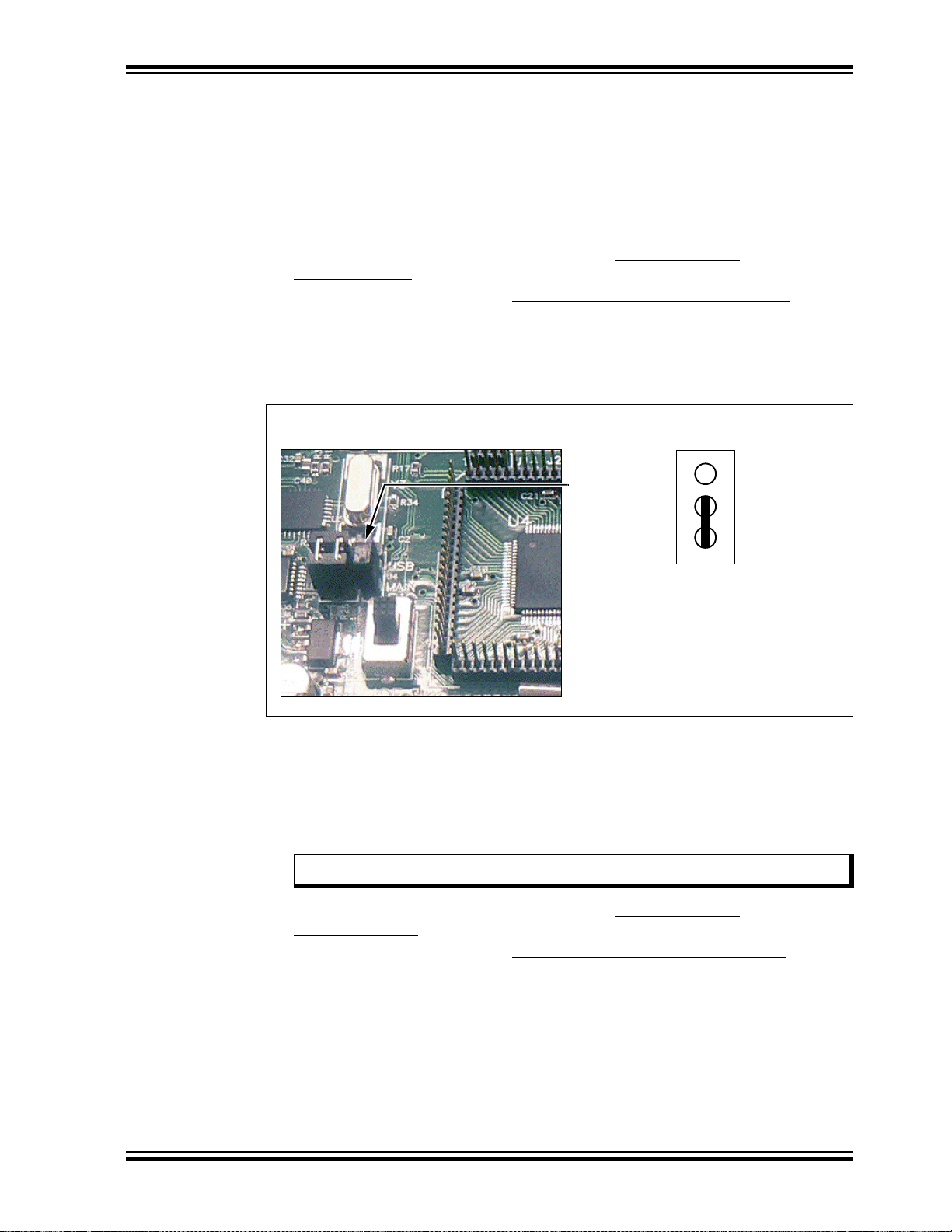
2.4.2 Loading the Program
J4 Jumper
Jumper Location Jumper Setting
USB
J4
Main
Getting Started
This section describes how to program the PICDEM PIC18 Explorer Demonstration
Board using th e MP LA B
Hex code on the compact disc in the PICDEM PIC18 Explorer Demonstration Board’s Kit.
2.4.2.1 REPROGRAMMING WITH THE COMPACT DISC SAMPLE CODE To program the PIC18F8722:
1. Launch the MPLAB IDE application and select Configure>Select
Device>18F8722.
2. To start the programmer, select Programmer>Select Programmer> ICD2
3. To open the Hex code file, select File>Import>Open
CD/Hex/18F8722/Demo8722.hex.
4. Connect the J4 jumper to Main (main controller), as shown in Figure 2-7.
FIGURE 2-7: J4 JUMPER AND ‘MAIN’ SETTING
®
Integrated Development Environment (IDE) and the sample
.
and select
5. Move the S4 switch to PIC MCU, as described in “Using the Board As Is” on
page 10.
To program the PIC18F87J11 on the PIM:
1. Attach the PIM to the demonstration board.
2. Move the S4 switch to ICE.
Note: Both steps 1 and 2 are described in “Attaching the PIM” on p age 13 .
3. Launch the MPLAB IDE application and select Configure>Select
© 2008 Microchip Technology Inc. DS51721B-page 17
Device>18F87J11.
4. To start the programmer, select Programmer>Select Programmer>ICD2
5. To open the Hex code file, select File>Import>Open
CD/Hex/18F87J11/Demo87J11.hex.
6. Connect the J4 jumper to Main (main controller), as shown in Figure 2-7.
and select
.
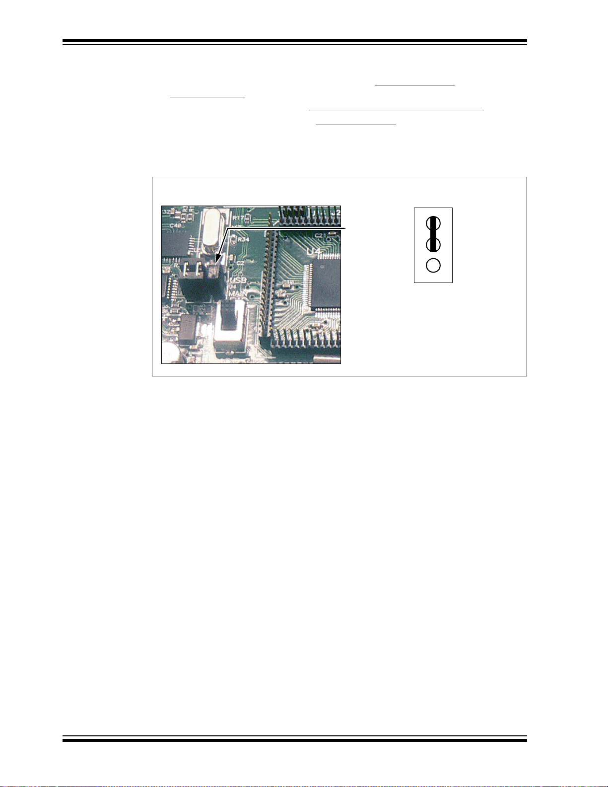
Page 22
PICDEM™ PIC18 Explorer Demonstration Board User’s Guide
J4 Jumper
Jumper Location Jumper Setting
USB
J4
Main
To program the PIC18LF2450 for RS-232 UART communication:
1. Launch the MPLAB IDE application and select Configure>Select
Device>18F2450.
2. To start the programmer, select Programmer>Select Programmer>ICD2
3. To open the Hex code file, select File>Import>Open
CD/Hex/RS232_USB_18F2450/Demo2450.hex.
4. Connect the J4 jumper to USB, as shown in Figure 2-8.
FIGURE 2-8: J4 JUMPER AND ‘USB’ SETTING
and select
.
DS51721B-page 18 © 2008 Microchip Technology Inc.
Page 23
Getting Started
Host
PC
Board
USB
DB9
PIC18LF2450
Microcontroller
J13
Main
PIC
®
MCU
UART Transceiver
Tx
Rx
Tx
Rx
Tx
Rx
X
1
X
2
Connecting to
Nine-Pin RS-232 Port
Connecting to
USB Port
J13
J13
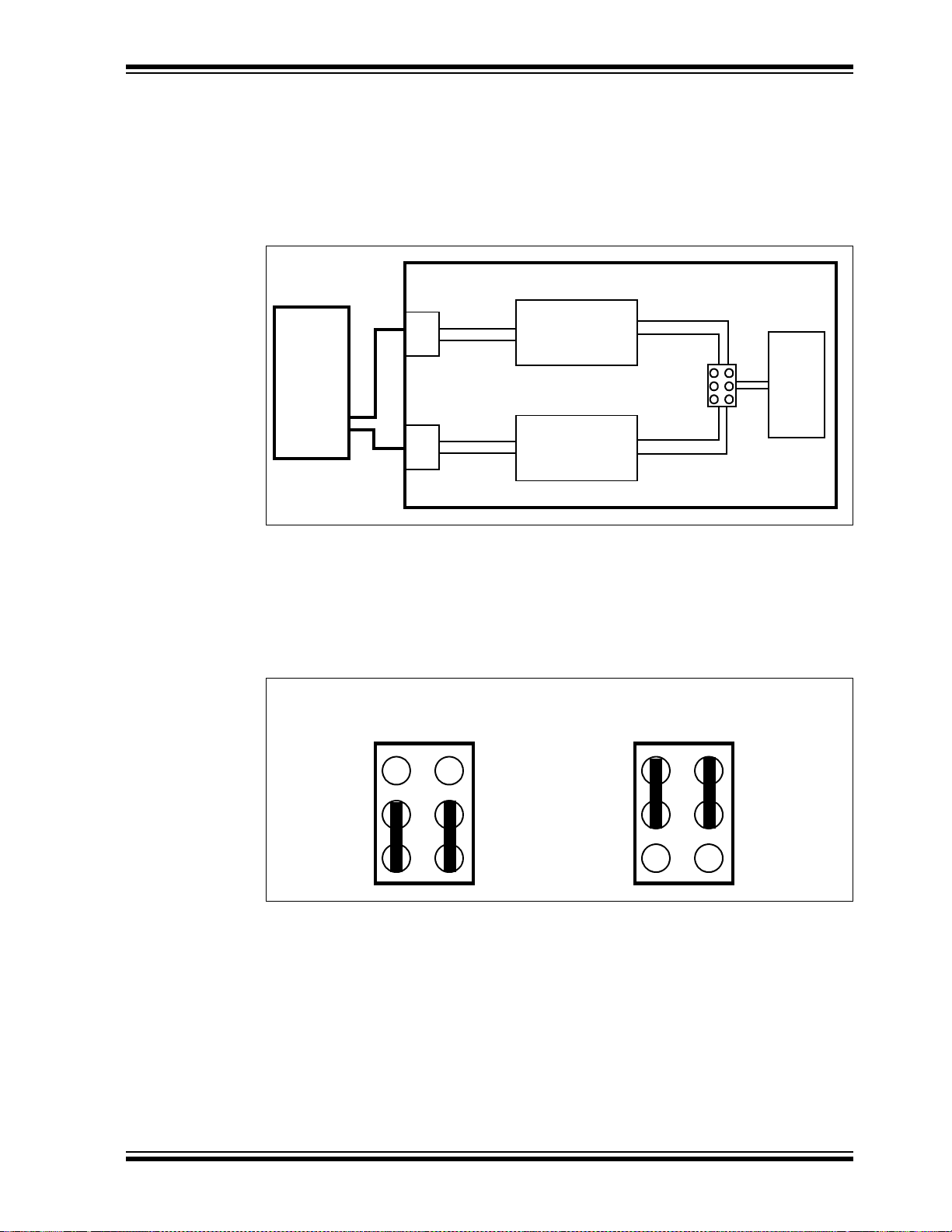
2.5 CONNECTING TO HOST PC FOR RS-232 COMMUNICATION
As shown in Figure 2-9, there are two ways to connect a PC to the PICDEM PIC18
Explorer Demonstration Board.
• Via the USB Port
• Via the DB9 Pin (RS-232 Port)
FIGURE 2-9: BOARD TO PC CONNECTION
2.5.1 PC Connection Via DB9 Pin
To connect the PICDEM PIC18 Explorer Demonstration Board to a host PC via the
nine-pin DB9 connector, set jumper J13, as shown in the first illustration in Figure 2-10.
This routes the main microcontroller’s communications through a transceiver.
FIGURE 2-10: JUMPER J13 – SETTINGS FOR RS-232 OR USB
© 2008 Microchip Technology Inc. DS51721B-page 19
Page 24
PICDEM™ PIC18 Explorer Demonstration Board User’s Guide
2.5.2 PC Connection Via USB Port
If the board PC communication is via the USB port, the data will be routed through the
PIC18LF2450 mounted on the board, to convert the RS-232 communication to the USB
protocol.
To connect the PICDEM PIC18 Explorer Demonstration Board to a host PC via the
USB port:
1. Set jumper J13, as shown in the second illustration in Figure 2-10.
2. Install the required file on the host PC. (See the following procedure.)
If the USB port is used, an *.inf file must be installed on the host PC. To do this:
1. Create a folder named, HPCINF, anywhere on the host PC’s hard drive.
2. Using the development kit’s CD, copy the file, mchpcdc.inf, into that folder.
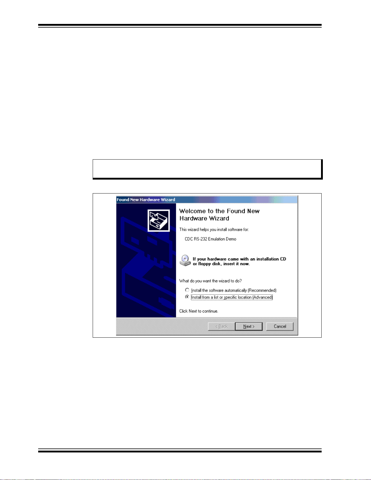
3. Connect the board to the PC and power up the board. The pop-up window,
shown in Figure 2-11, appears.
Note: This procedure displays the dialog boxes that appear for the Windows
operating system.
FIGURE 2-11: INSTALLING USB *.inf FILE ON PC – SCREEN 1
®
XP
4. Select the Install from a list or specific location option and click Next. The
screen shown in Figure 2-12 appears.
DS51721B-page 20 © 2008 Microchip Technology Inc.
Page 25
Getting Started
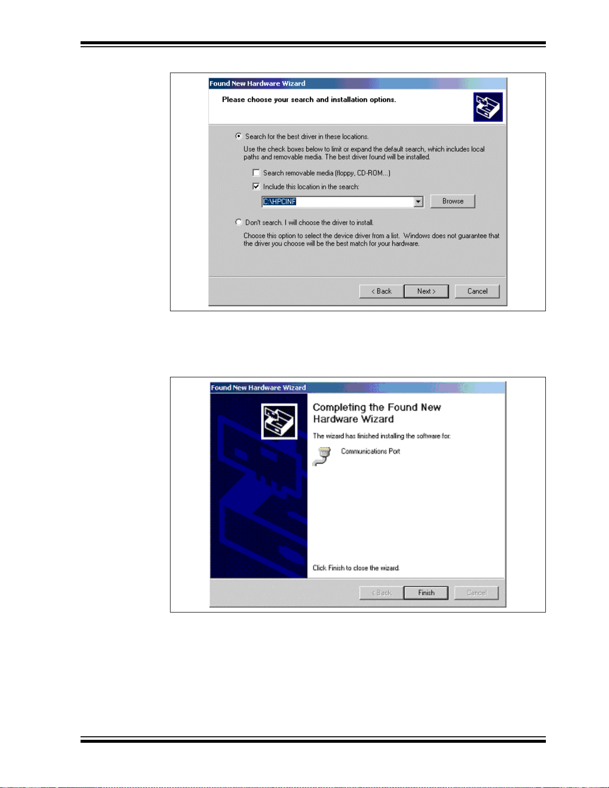
FIGURE 2-12: INSTALLING USB *.inf FILE ON PC – SCREEN 2
5. Select the check box, Include this location in the search, enter the name of
the path (created in Step 1) in the text box below and click Next. The scre en
shown in Figure 2-13 appears.
FIGURE 2-13: INSTALLING USB *.inf FILE ON PC – SCREEN 4
6. Press Finish. The RS-232 to USB functionality is ready to be used.
© 2008 Microchip Technology Inc. DS51721B-page 21
Page 26

PICDEM™ PIC18 Explorer Demonstration Board User’s Guide
NOTES:
DS51721B-page 22 © 2008 Microchip Technology Inc.
Page 27

PICDEM™ PIC18 EXPLORER
RB0 Button
RA5 Button
DEMONSTRATION BOARD
USER’S GUIDE
Chapter 3. PICDEM™ PIC18 Explorer Demonstration
Board Tutorial Program
The tutorial program is preprogrammed into the PIC18F8722 on the PICDEM PIC18
Explorer Demonstration Board. This program is also on the PICDEM PIC18 Explorer
Demonstration Board kit’s CD-ROM so that it can be reprogrammed on the sample
device if it the device had been preprogrammed.
For detailed information on the PICDEM PIC18 Explorer Demonstration Board
hardware, see Appendix A. “Hardware Details”.
3.1 T UTORIAL PROGRAM OPERATION
The tutorial program consists of three components that appear sequentially on the
board’s LCD. A flowchart, showing the button navigation through the entire program, is
given in Figure 3-2.
When the board boots up, the device name appears on the LCD and the program
proceeds to the first component.
To select menu options, use the RB0 and RA5 buttons on the bottom of the board (see
Figure 3-1).
FIGURE 3-1: RB0 AND RA5 BUTTONS
1. Voltmeter
This mode uses the Analog-to-Digital Converter (A/D) module to measure the voltage
of the R3 potentiometer and display a value between 0.00V and 5.00V on the LCD. (In
the case of 3.3V devices, the displayed value will be 0.00V to 3.3V.)
The voltage reading is updated continually until the mode is exited by pressing RB0.
2. Temperature
This mode uses an MCP9701A thermal sensor to measure ambient temperature in
Celsius and displays it on the LCD. The program also stores the current temperature,
when exited, by writing to a defined address on the external, on-board EEPROM.
Communication between the micr ocontr ol ler and sens or is done by the A/D mod ule .
To exit this mode, press RB0.
© 2008 Microchip Technology Inc. DS51721B-page 23
Page 28

PICDEM™ PIC18 Explorer Demonstration Board User’s Guide
3. Clock
Once this mode is entered from the main menu, a Real-Time Clock (RTC) will start
counting from 00:00:00. The Timer1 module uses a 32-kHz clock crystal to establish
the clock.
The program also sends the time data to the RS-232 serial port using the Universal
Asynchronous Receiver Transmitter (UART) on the microcontroller. This enables the
host PC to display the LCD’s data using the Hyper Terminal application on the PC.
Note: For information on connecting the board’s RS-232 serial port to the PC, see
Section 2.5 “Connecting to Host PC for RS-232 Communication”.
If using the Hyper Terminal application, use the settings given in Table 3-1.
TABLE 3-1: HYPER TE RMINAL SETTINGS
Field Setting
Bits per second
Data bits 8
Parity None
Stop bits 1
Flow control None
9600
To set the clock time:
1. Enter the clock-setting program by pressing RB0. The clock begins running.
2. To set the hours value, press RA5.
3. Increment the hours to the desired value by pressing RB0.
4. To set the minutes value, press RA5.
5. Increment the minutes to the desired value by pressing RB0.
6. T o start the clock with the set time, press RA5. The LCD returns to an active clock
display.
7. To return to the main menu, press RB0.
DS51721B-page 24 © 2008 Microchip Technology Inc.
Page 29

Tutorial Program
Power-up
PICDEM™ PIC18 Explorer
Voltmeter
RA5 = Next
RB0 = Now
Temperature
RA5 = Next
RB0 = Now
Clock
RA5 = Next
RB0 = Now
Volt = n.nnV
RB0 = Exit
Temperature - 022°C
RB0 = Exit
00.00.02
RA5 = Set, RB0 = Menu
00.00.03
RA5 = ->, RB0 = ++
FIGURE 3-2: TUTORIAL PROGRAM FLOWCHART
3.2 SOURCE CODE AND DATA SHEETS
The PICDEM PIC18 Explorer Demonstration Board Kit’s CD-ROM contains the
assembled tutorial program (the Hex files) as well as the source code used to create
those Hex file s. The CD has de vice-specif ic director ies for each set o f source code and
Hex files.
For information on reprogramming the device with new or modified code, see
Section 2.1 “Board as Stand-Alone Device”.
© 2008 Microchip Technology Inc. DS51721B-page 25
Page 30

PICDEM™ PIC18 Explorer Demonstration Board User’s Guide
NOTES:
DS51721B-page 26 © 2008 Microchip Technology Inc.
Page 31

Appendix A. Hardware Details
A.1 HARDWARE ELEMENTS
A.1.1 Processor Sockets
The PICDEM PIC18 Explorer Demonstration Board can be populated with 64 and
80-pin devices. Using a Plug-In Module (PIM), the board also can support 28, 44, 64
and 80-pin devices.
For a list of available PIMs, go to the Microchip web site at http://microchip.com
A.1.2 Display
Eight LEDs are connected to PORTD of the PICDEM PIC18 Explorer Demonstration
Board. The PORTD pins are set high to light the LEDs.
These LEDs may be disconnected by removing jumper JP1.
One LED (D9) lights to indicate when the board has power.
PICDEM™ PIC18 EXPLORER
DEMONSTRATION BOARD
USER’S GUIDE
.
A.1.3 Power Supply
The PIC18 Explorer Board does not come with a power supply . It can be powered, via
J1, with an unregulated DC supply of 9V to 15V. The preferred supply is 9V.
For default functionality, a power supply with a current capability of 250 mA is sufficient.
Since the board can serve as a modular development platform connecting to multiple
expansion boards, voltage regulators (Q1 and Q2) are used. Their maximum current
capability is 800 mA. This current capacity may require a power supply of up to 1.6A.
Because the regulators do not have heat sinks, long-term operation at such loads is not
recommended.
When the board is powered, LED D9 is on, indicating the presence of V_VAR.
If an external supply is needed, Microchip’s 9V, 750 mA power supply (part number
AC162039) can be used.
Note: Do not attempt to power the PICDEM PIC18 Explorer Demonstration Board
using the MPLAB ICD 2 module. That module is not designed to be a USB
bus power source.
A.1.4 RS-232 Serial Port
An RS-232, level-shifting integrated circuit has been provided with all the necessary
hardware to support the connection of an RS-232 host through the DB9 connector. The
port can be connected to a PC using a straight-through cable.
The PIC18 receive and transmit pins are tied to the receive and transmit lines of the
MAX3232 transceiver through jumper J13. That jumper can direct where the receive
and transmit pins of the PIC18 are connected, either to:
• The PIC18LF2450 which does the RS-232 to USB communication
• The MAX3232 transceiver
Note: For details on this connection, see Section 2.5 “Connecting to Host PC
for RS-232 Communication”.
© 2008 Microchip Technology Inc. DS51721B-page 27
Page 32

PICDEM™ PIC18 Explorer Demonstration Board User’s Guide
A.1.5 Switches
The following switches are available:
• S1 – Active-low switch connected to RB0
• S2 – Active-low switch connected to RA5
• S3 – MCLR
• S4 – MCLR
If the on board, PIC18F8722 microcontroller is being used, set this to PIC MCU.
If an alternate, PIM-mounted microcontroller is being used, set this to ICE.
A.1.6 Oscillator Options
The main oscillator uses a 10 MHz crystal (Y1) which serves as the controller’s primary
oscillator. A second circuit, using a 32.768-kHz (watch type) crystal (Y2), functions as
the Timer1 oscillator, the source for the Real-Time Clock/Calendar (RTCC) and
secondary oscillator.
The PIC18LF2450, the heart of the RS-232 to USB conversion, is independently
clocked with its own 12 MHz crystal (Y3).
A.1.7 Analog Input (Potentiometer)
A 10 kΩ potentiometer is connected through a series resistor to AN0. To provide an
analog input to one of the controller’s Analog-to-Digital (A/D) channels, the
potentiometer can be adjusted from V
to hard reset the processor
select switch.
DD to GND.
A.1.8 ICD Connector
Microchip’s low-cost, in-circuit debugger, MPLAB ICD 2, can be connected to the
modular connector (J10). The ICD connector utilizes RB6 and RB7 for in-circuit
debugging.
Note: For details, see Section 2.4.1 “Programming Requirements”.
A.1.9 PICkit™ 2 Connector
Microchip’s low-cost programmer, PICkit 2, can be connected to the 6-pin interface
provided by J12.
Note: For details, see Section 2.4.1 “Programming Requirements”.
A.1.10 Temperature Sensor
The analog thermal sensor, MCP9701A (U1), is used for monitoring temperature. The
device is connected to the Analog-to-Digital Converter (A/D) module through RA1.
A.1.11 Serial EEPROM
A 25LC256, 256 Kbit (32K x 8) serial EEPROM (U9) is included for nonvolatile storage
of firmware.
The EEPROM also can demonstrate the operation of the Serial Peripheral Interface
(SPI) bus. The EEPROM is enabled or disabled from the SPI bus by jumper JP2.
A.1.12 PICtail™ Daughter Board Connector
The PICtail™ interface enables the PICDEM PIC18 Explorer Demonstration Board to
be connected directly to available PICtail daughter board cards. This provides a
one-to-one connection between the microcontrollers and the cards through SPI/I
interfaces.
DS51721B-page 28 © 2008 Microchip Technology Inc.
2
C™
Page 33

A.1.13 LCD
An LCD display with two lines, 16 characters each, is connected to the SPI I/O
expander, MCP23S17. The two control lines and eight data lines are connected to the
I/O expander.
The I/O expander has an SPI interface that connects it to the microcontroller.The I/O
expander is disabled or enabled from the SPI by jumper JP3.
A.1.14 Sample Devices
A sample part programmed with a simple program is included in the PICDEM PIC18
Explorer Demonstration Board Kit. The devices’ I/O features and port connections are
listed in Table A-1.
TABLE A-1: SAMPLE DEVICE I/O FEATURES AND CONNECTIONS
Device LEDs
RS-232/
USB
S1 S2 S3 LCD
Pot
R3
Hardware Details
EEPROM
Temp
Sensor
ICD/
PICkit™ 2
Y1,
Y2
PIC18F8722 RD7:RD0 RC6/RC7 RB0 RA5 MCLR
PIC18F87J11 RD7:RD0 RC6/RC7 RB0 RA5 MCLR RC3:RC5 RA0 RC3:RC5 RA1 RB6/RB7 Yes
RC3:RC5 RA0 RC3:RC5 RA1 RB6/RB7 Yes
© 2008 Microchip Technology Inc. DS51721B-page 29
Page 34
PICDEM™ PIC18 Explorer Demonstration Board User’s Guide
PICDEM™ PIC18
EXPLORER
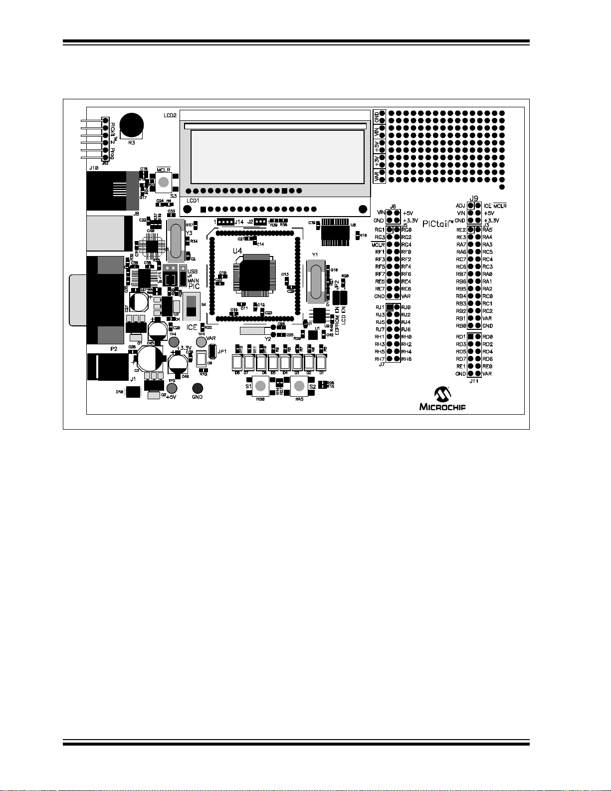
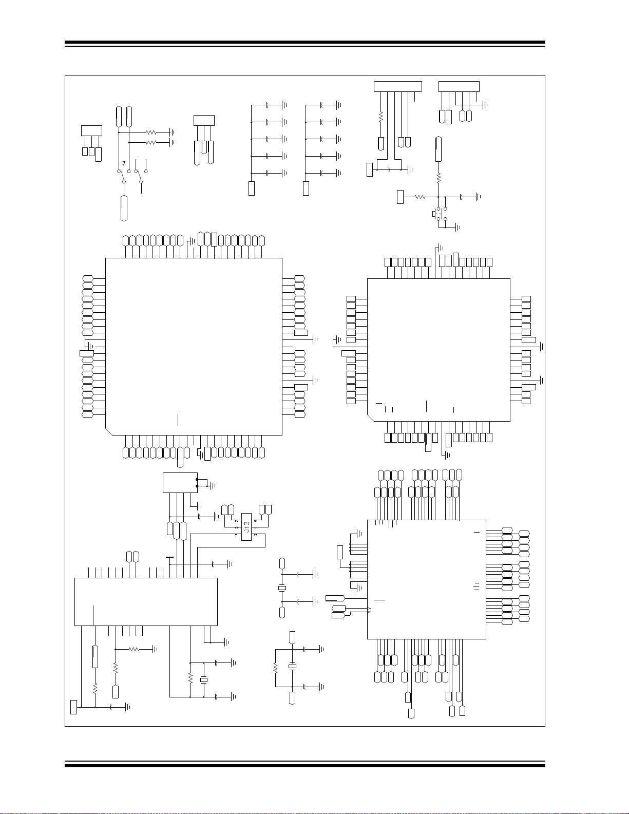
A.2 BOARD LAY O UT AND SCHEMATICS
FIGURE A-1: PICDEM™ PIC18 EXPLORER DEMONSTRATION BOARD LAYOUT
DS51721B-page 30 © 2008 Microchip Technology Inc.
Page 35
Hardware Details
PIC tai l
RA0
RB0
RD7
RD5
RD4
RD2
RD1
1k
R10
1k
R7
RB1
RC5
RC3
V_VAR
DB6
DB5
DB3
DB2
DB0
RA1
V_VAR
RC4
RB2
TXD
RS
V_VAR
RC3
V_VAR
DB4
DB2
VO
DB4
DB2
VO
RH5
RH3
RJ7
RJ5
RJ1
RE7
RE5
RF5
RF3
RG5
RG3
RD7
RD5
RD1
RB0
RB2
RB3
RB5
RB6
RC6
RC7
RA7
RE3
ICEMCLR
RH4
RH2
RJ6
RJ4
RJ0
RE6
RE4
RF4
RF2
RG4
RG2
RD6
RD4
RD0
RC2RC2
RC1RC1
RA2RA2
RA1RA1
RC3RC3
RC4RC4
RA3RA3
RA4RA4
C24
TBD
POT
4
32
1
S1
V_VAR
VIN
Power
330_1%
R26
4
32
1
S2
RD6
RD3
RD0
+3.3V
+5V
D9
1k
R12
1k
R9
1k
R11
1k
R6
1k
R8
1k
R5
RA2
V_VAR
RA3
C35
.1uF
V_VAR
DB7
DB4
V_VAR
DB1
15K
R40
E
C42
.1uF
RC5
V_VAR
C38
.1uF
DB6
RS
DB0
DB6
RS
DB0
RH7
RH1
RJ3
RF7
RF1
RG1
RE1
RD3
RB1
RB4
RB7
RA6
RE2
J9
1 2
3 4
J6
+3.3V
RH6
+3.3V
RH0
RJ2
RF6
RF0
RG0
RE0
RD2
V_VAR
TM
RC0
RA0RA0
RC0
RC5
RA5RA5
RC5
S1GB13
15K
R14
C28
.1uF
C4
.1uF
C29
.1uF
C30
.1uF
V_VAR
R13
1k
R20
15K
V_VAR
C36
.1uF
C37
.1uF
9
PIN98PIN87PIN76PIN6
1
PIN12PIN23PIN34PIN45PIN5
80 - 84 pins
64 - 68 pins
40 - 44 pins
8 - 14 - 18 - 20 - 28 pins
J14
1
14
2
3 4
5 6
7 8
9 10
11 121315 16
17 18
19 20
J5
16
15
9 10
3 4
1413
11 12
5 6
1 2
7 8
J7
1 235
7
468
11 12
9 10
J11
R4
1K
Switch
RXD
RA5
DB7
DB5
DB1
E
Temperature Sensor
DB7
DB5
DB1
E
ICEMCLR
VIN
VIN
ADJ
VIN
RH4RH5
RH2RH3
RJ6RJ7
RJ4RJ5
RJ0RJ1
RE6RE7
RE4RE5
RF4RF5
RF2RF3
RG4PICMCLR
RG2RG3
V_VAR
RD6RD7
RD4RD5
RD0RD1
RB0
RB2
RB3
RB5
RB6
RC6
RC7
OSC1
RE3
C3
220uF ECE-V1EA221UP
V_VAR
R15
1K
TP2
C34
.1uF
TP1
V_VAR
TP4
TP5
Power Indicator
R28
1K
V_VAR
D8
JP1
D5
D6
D7
C1
.1uF
D2
D3
D4
D1
V_VAR
R32
10
RF6
V_VAR
+5V
DB3
+5V
DB3
+5V
+3.3V
+5V
+5V
+5V
RH6RH7
RJ2
RH0
RJ3
RH1
V_VAR
RF6RF7
RG0
RF0
RG1
RF1
RD2
RE0
RD3
RE1
RB1
RB7
RB4
RE2
OSC2
132
ADJ
R25
1K_1%
C27
100uf ECE-V1AA101WR
47uF
C45
47uF
C49
C39
.1uF
JP3
15K
R27
11
DIN110DIN212ROUT19ROUT23C1-1C1+5C2-4C2+6V-2V+
15
GND
16
VCC
8
RIN213RIN1
7
DOUT214DOUT1
U6
MAX3232
R16
15K
MCP23S17
1K
R38
10K
R39
25LC256
5 6
7 8
9 10
11 12
13 14
15 16
17 18
19 20
21 22
23 24
25 26
27 28
1 2
3 4
J3
MCP9701A
R36
470
1K
R29
JP2
1
ADJUST
3
IN
2
OUT
LM317
R35
470
1
GND
3
IN
2
OUT
LM1117
LCM-SO1602 DTR/M
1
GND
3
IN
2
OUT
LM1117
15
LED_+13D610D37D04RS1Vss
14D716
LED_-
9D26E3
Vo
11
D48D1
2
Vdd5R/W
12
D5
MDLS-16264 S S-DIF
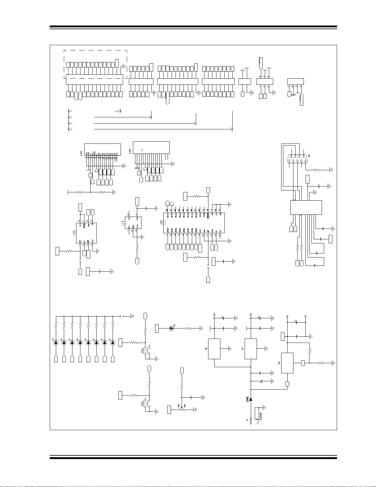
FIGURE A-2: PICDEM™ PIC18 EXPLORER DEMONSTRATION BOARD SCHEMATIC – 1 OF 2
© 2008 Microchip Technology Inc. DS51721B-page 31
Page 36
PICDEM™ PIC18 Explorer Demonstration Board User’s Guide
RD0
RD1
RD3
RD4 OSC2
RD6
RD7
RE0
RE2
RE3
RE5
RE6
RF1
RF2
RF4
RF5
RF7
RH5
RH4
RF0 RE3
RF0
RE4
V_VAR
RA3 RE6 RA3
RA2 RE7 RA2
RA0 V_VAR RA0
RA5 RD2
V_VAR
RA4 RD3 RA5
RC0
RD5
RC1
RC6
RD6
RC0
RC7
RJ4
PICMCLR
RH1
RH0
RE3
V_VAR RE4
RE6
RE7
V_VAR
RD1
RD2
RD4
RD5
RD7
RJ0
RC7
RC4
RB2
RC6
RC3
RC0
RB4
RB1
RA4
RA0
VBUS
V_VAR
RB7
RC6
RC7
RG0
RG2
RH2
RH4
RJ0
RJ4
RJ6
RF2
RF3
RF5
RF6
V_VAR
PICMCLR
RG3
RG1
RG0
RE1
PIC18F6627
PIC18F6622
RC2
RC3
RC5
RB7
OSC1
OSC2
RB6
RB5
RB3
RB2
RB0
RJ7
RC2
RC4
RC5
V_VAR
OSC1
RB5
RB4
RB2
RB1
RJ3
RJ2
V_VAR
MAIN_
MCLR
RB6
RB7
MCLR
MCLR
MAIN_
MCLR
ADJ
VIN
RB6
RB7
V_VAR
MCLR
C31
.1uF
RB6
RC2
RA2
RB0
C15
22pf
R34
1M
C16
22pf
OSC2
RD2
RE1
RD5
OSC1
RC0
RF3
RE4
RF0
RE7
RC1
+3.3V
RB6
RF6
TXD
RXD
VBUS
RH6
RH0
RG4
RJ2
RF7
RF4
RG2
RG4
RE0
RF1
RE5
RE2
RF1
RA1
PIC18F6527
RD1
RD0 RA1
RC7
RC1
RD7
RD4
RC6
RA4
RC4
RB4
RB1
RJ5
RJ6
RB7
RC3
OSC2
RB6
RB0
RB3
V_VAR
V_VAR
C11
.1uF
USB_MCLR
V_VAR
ICD Connector
C13
.1uF
C14
.1uF
PICMCLR
ICEMCLR
12Mhz
Y3
47K
R19
C25
22pf
C26
22pf
C40
.47uF
C32
.1uF
RE5
RE2
V_VAR
RD0
RD6
RD3
RJ1
C18
.1uF
4.7K
R18
C19
.1uF
R17
47K
C20
.1uF
C21
.1uF
RC1
RB7
RB5
RA3
RA1
R37
33K
USB_MCLR
RG3
PIC18F8627 RH1
PIC18F8527 RH5
RH7
RJ1
RJ3
RJ7
RH7
RF2
RF4
RF5
RF7
V_VAR
USB_D+
RG4
USB_D-
RG3
RG2
RG0
RE0
RH3
RH2
MAIN_
MCLR
RC5
RB3
RA5
OSC1
R21
1M
R33
10K
V_VAR
RG1
PIC18F8622 RH3
RJ5
RH6
RF6
RF3
ICEMCLR
RE1
RG1
V_VAR
4
32
1
S3
R23 1k
C17
.1uF
C10
.1uF
C12
.1uF
10Mhz
Y1
341
2
5 6
J8
C22
.1uF
C23
.1uF
V_VAR
213
J2
R22
47K
123
J4
C2
22pf
C33
22pf
12346
5
J10
R24
100
12345
6
J12
PICKIT2 Programmer
32Khz
Y2
5
VSS
17
VDD
23
RB5
20
RB2
7
OSC2
15
RC7/RX
14
RC6/TX
9
RC18RC0
22
RB421RB3
6
OSC1
16
VSS
11
Vusb
25
RB724RB6
19
RB118RB0
4
RA5/AN4
1
RA2/VREF-27RA0/AN028RA1/AN12RA3/VREF+3RA4/RCV
26
MCLR/RE3
13
RC5/D+/VP
10
RC2/CCP1
12
RC4/D-/VM
U5
PIC18LF2450
72
RD0/PSP0/AD0
67
RD3/PSP3/AD3
64
RD6/PSP6/AD6
78
RE2/CS/A D10
75
RE5/AD13
23
RF1/AN6/ C2OUT
16
RF4/AN9
13
RF7/SS1
49
OSC1/CLKI/RA7
32
VDD
70
VSS
11
VSS
69
RD1/PSP1/AD1
66
RD4/PSP4/AD4
68
RD2/PSP2/AD2
63
RD7/PSP7/AD7
4
RE0/RD/AD8
77
RE3/AD11
74
RE6/AD14
76
RE4/AD12
3
RE1/WR/AD9
18
RF2/AN7/ C1OUT
15
RF5/AN10/ CVREF
24
RF0/AN5
17
RF3/AN8
14
RF6/AN11
26
AVSS
71
VDD
25
AVDD
48
VDD
9
MCLR/VPP
51
VSS
31
VSS
50
OSC2/CLKO/RA6
46
RC5/SDO143RC2/ECCP1
52
RB6/KBI2PGC55RB3/INT3/ECCP258RB0/INT033RA5/AN4/HLVDIN28RA2/AN2/VREF-
7
RG2/RX2/DT2
80
RH1/A17
22
RH4/AN1219RH7/AN15
62
RJ0/ALE
59
RJ3/WRH
41
RJ6/LB
65
RD5/PSP5/AD5
73
RE7/CCP2/AD15
37
RC6/TX1/CK138RC7/RX1/DT1
36
RC0/T1OSO/T13CKI47RB7/KBI3/PGD54RB4/KBI0
35
RC1/T1OSI/CCP2
53
RB5/KBI1/PGM
44
RC3/SCK1/SCL1
57
RB1/INT1
27
RA3/AN3/VREF+30RA0/AN034RA4/T0CKI29RA1/AN1
5
RG0/CCP3
10
RG4/CCP5
79
RH0/A162RH3/A19
8
RG3/CCP4
1
RH2/A18
21
RH5/AN13
60
RJ2/WRL
39
RJ4/BA0
42
RJ7/UB61RJ1/OE
40
RJ5/CE
56
RB2/INT2
45
RC4/SDI1/SDA1
12
VDD
6
RG1/TX2/CK2
20
RH6/AN14
U4
PIC18F8722
1
RE1/WR/P2C2RE0/RD/P2D3RG0/ECCP3/P3A4RG15RG26RG3/P3D7RG5/MCLR/VPP8RG4/P1D9VSS10VDD11RF7/
SS
12
RF6/AN1113RF5/AN10/CVREF14RF4/AN915RF3/AN816RF2/AN7
48
RB0/INT047RB1/INT146RB2/INT245RB3/INT344RB4/KBI0
43
RB5/KBI1/PGM
42
RB6/KBI2/PGC
41
VSS
40
RA6/OSC2/CLKO
39
RA7/OSC1/CLKI
38
VDD
37
RB7/KBI3/PGD
36
RC5/SDO1
35
RC4/SDI1/SDA1
34
RC3/SCK1/SCL1
33
RC2/ECCP1/P1A
17
RF1/AN6
18
RF0/AN5
19
AVDD
20
AVSS
21
RA3/AN3/VREF+
22
RA2/AN2/VREF-
23
RA1/AN1
24
RA0/AN0
25
VSS
26
VDD
27
RA5/AN4/LVDIN
28
RA4/T0CKI
29
RC1/T1OSI/ECCP2/P2A
30
RC0/T1OSO/T13CKI
31
RC6/TX/CK1
32
RC7/RX/DT1
64
RE2/CS/P2B
63
RE3/P3C
62
RE4/P3B
61
RE5/P1C
60
RE6/P1B
59
RE7/ECCP2/P2A
58
RD0/PSP0
57
VDD
56
VSS
55
RD1/PSP1
54
RD2/PSP2
53
RD3/PSP3
52
RD4/PSP4
51
RD5/PSP5
50
RD6/PSP6
49
RD7/PSP7
U7
PIC18F6522
33
RH5
36
RF0
39
RA3
42
RA0
45
VDD
51
RC7
11
RH1
8
RE3
5
RE6
2
VDD
83
RD1
48
RC1/T1OSI
80
RD4
77
RD7
32
RH6
29
RF3
26
RF6
23
VSS
20
RG5/MCLR
17
RG1
14
RE1
54
RJ6
57
RC3
60
RB7
63
OSC2/RA6
66
RB6
69
RB3
72
RB0
27
RF528RF430RF231RH7
21
RG422NC24VDD25RF7
18
RG219RG3
15
RE016RG0
12
RH213RH3
38
AVSS
35
RF1
37
AVDD
41
RA1
43
NC
44
VSS
47
RA4
50
RC6
53
RJ5
58
RC459RC556RC2
55
RJ7
61
VDD
62
OSC1
64
NC
65
VSS
71
RB170RB267RB568RB4
74
RJ273RJ3
6
RE5
9
RE2
7
RE4
3
RD0
1
NC
84
VSS
49
RC0/T1OSO
81
RD3
79
RD5
78
RD6
75
RJ1
34
RH4
40
RA2
46
RA5
52
RJ4
10
RH0
4
RE7
82
RD2
76
RJ0
U1A
ICE MODULE
FIGURE A-3: PICDEM™ PIC18 EXPLORER DEMONSTRATION BOARD SCHEMATIC – 2 OF 2
DS51721B-page 32 © 2008 Microchip Technology Inc.
Page 37

NOTES:
Hardware Details
© 2008 Microchip Technology Inc. DS51721B-page 33
Page 38

WORLDWIDE SALES AND SERVICE
AMERICAS
Corporate Office
2355 West Chandler Blvd.
Chandler, AZ 85224-6199
Tel: 480-792-7200
Fax: 480-792-7277
Technical Support:
http://support.microchip.com
Web Address:
www.microchip.com
Atlanta
Duluth, GA
Tel: 678-957-9614
Fax: 678-957-1455
Boston
Westborough, MA
Tel: 774-760-0087
Fax: 774-760-0088
Chicago
Itasca, IL
Tel: 630-285-0071
Fax: 630-285-0075
Dallas
Addison, TX
Tel: 972-818-7423
Fax: 972-818-2924
Detroit
Farmington Hills, MI
Tel: 248-538-2250
Fax: 248-538-2260
Kokomo
Kokomo, IN
Tel: 765-864-8360
Fax: 765-864-8387
Los Angeles
Mission Viejo, CA
Tel: 949-462-9523
Fax: 949-462-9608
Santa Clara
Santa Clara, CA
Tel: 408-961-6444
Fax: 408-961-6445
Toronto
Mississauga, Ontario,
Canada
Tel: 905-673-0699
Fax: 905-673-6509
ASIA/PACIFIC
Asia Pacific Office
Suites 3707-14, 37th Floor
Tower 6, The Gateway
Harbour City, Kowloon
Hong Kong
Tel: 852-2401-1200
Fax: 852-2401-3431
Australia - Sydney
Tel: 61-2-9868-6733
Fax: 61-2-9868-6755
China - Beijing
Tel: 86-10-8528-2100
Fax: 86-10-8528-2104
China - Chengdu
Tel: 86-28-8665-5511
Fax: 86-28-8665-7889
China - Hong Kong SAR
Tel: 852-2401-1200
Fax: 852-2401-3431
China - Nanjing
Tel: 86-25-8473-2460
Fax: 86-25-8473-2470
China - Qingdao
Tel: 86-532-8502-7355
Fax: 86-532-8502-7205
China - Shanghai
Tel: 86-21-5407-5533
Fax: 86-21-5407-5066
China - Shenyang
Tel: 86-24-2334-2829
Fax: 86-24-2334-2393
China - Shenzhen
Tel: 86-755-8203-2660
Fax: 86-755-8203-1760
China - Wuhan
Tel: 86-27-5980-5300
Fax: 86-27-5980-5118
China - Xiamen
Tel: 86-592-2388138
Fax: 86-592-2388130
China - Xian
Tel: 86-29-8833-7252
Fax: 86-29-8833-7256
China - Zhuhai
Tel: 86-756-3210040
Fax: 86-756-3210049
ASIA/PACIFIC
India - Bangalore
Tel: 91-80-4182-8400
Fax: 91-80-4182-8422
India - New Delhi
Tel: 91-11-4160-8631
Fax: 91-11-4160-8632
India - Pune
Tel: 91-20-2566-1512
Fax: 91-20-2566-1513
Japan - Yokohama
Tel: 81-45-471- 6166
Fax: 81-45-471-6122
Korea - Daegu
Tel: 82-53-744-4301
Fax: 82-53-744-4302
Korea - Seoul
Tel: 82-2-554-7200
Fax: 82-2-558-5932 or
82-2-558-5934
Malaysia - Kuala Lumpur
Tel: 60-3-6201-9857
Fax: 60-3-6201-9859
Malaysia - Penang
Tel: 60-4-227-8870
Fax: 60-4-227-4068
Philippines - Manila
Tel: 63-2-634-9065
Fax: 63-2-634-9069
Singapore
Tel: 65-6334-8870
Fax: 65-6334-8850
Tai wan - Hsin Chu
Tel: 886-3-572-9526
Fax: 886-3-572-6459
Taiwan - Kaohsiung
Tel: 886-7-536-4818
Fax: 886-7-536-4803
Taiwan - Taipei
Tel: 886-2-2500-6610
Fax: 886-2-2508-0102
Thailand - Bangkok
Tel: 66-2-694-1351
Fax: 66-2-694-1350
EUROPE
Austria - Wels
Tel: 43-7242-2244-39
Fax: 43-7242-2244-393
Denmark - Copenhagen
Tel: 45-4450-2828
Fax: 45-4485-2829
France - Paris
Tel: 33-1-69-53-63-20
Fax: 33-1-69-30-90-79
Germany - Munich
Tel: 49-89-627-144-0
Fax: 49-89-627-144-44
Italy - Milan
Tel: 39-0331-742611
Fax: 39-0331-466781
Netherlands - Drunen
Tel: 31-416-690399
Fax: 31-416-690340
Spain - Madrid
Tel: 34-91-708-08-90
Fax: 34-91-708-08-91
UK - Wokingham
Tel: 44-118-921-5869
Fax: 44-118-921-5820
01/02/08
DS51721B-page 34 © 2008 Microchip Technology Inc.
 Loading...