

Page 1
PICDEM™ Lab II
Development Board
User’s Guide
2015 Microchip Technology Inc. DS40001814A
Page 2

Note the following details of the code protection feature on Microchip devices:
YSTEM
CERTIFIED BY DNV
== ISO/TS 16949 ==
• Microchip products meet the specification contained in their particular Microchip Data Sheet.
• Microchip believes that its family of products is one of the most secure families of its kind on the market today, when used in the
intended manner and under normal conditions.
• There are dishonest and possibly illegal methods used to breach the code protection feature. All of these methods, to our
knowledge, require using the Microchip products in a manner outside the operating specifications contained in Microchip’s Data
Sheets. Most likely, the person doing so is engaged in theft of intellectual property.
• Microchip is willing to work with the customer who is concerned about the integrity of their code.
• Neither Microchip nor any other semiconductor manufacturer can guarantee the security of their code. Code protection does not
mean that we are guaranteeing the product as “unbreakable.”
Code protection is constantly evolving. We at Microchip are committed to continuously improving the code protection features of our
products. Attempts to break Microchip’s code protection feature may be a violation of the Digital Millennium Copyright Act. If such acts
allow unauthorized access to your software or other copyrighted work, you may have a right to sue for relief under that Act.
Information contained in this publication regarding device
applications and the like is provided only for your convenience
and may be superseded by updates. It is your responsibility to
ensure that your application meets with your specifications.
MICROCHIP MAKES NO REPRESENTATIONS OR
WARRANTIES OF ANY KIND WHETHER EXPRESS OR
IMPLIED, WRITTEN OR ORAL, STATUTORY OR
OTHERWISE, RELATED TO THE INFORMATION,
INCLUDING BUT NOT LIMITED TO ITS CONDITION,
QUALITY, PERFORMANCE, MERCHANTABILITY OR
FITNESS FOR PURPOSE. Microchip disclaims all liability
arising from this information and its use. Use of Microchip
devices in life support and/or safety applications is entirely at
the buyer’s risk, and the buyer agrees to defend, indemnify and
hold harmless Microchip from any and all damages, claims,
suits, or expenses resulting from such use. No licenses are
conveyed, implicitly or otherwise, under any Microchip
intellectual property rights unless otherwise stated.
Trademarks
The Microchip name and logo, the Microchip logo, dsPIC,
FlashFlex, flexPWR, JukeBlox, K
LANCheck, MediaLB, MOST, MOST logo, MPLAB,
OptoLyzer, PIC, PICSTART, PIC
SST, SST Logo, SuperFlash and UNI/O are registered
trademarks of Microchip Technology Incorporated in the
U.S.A. and other countries.
The Embedded Control Solutions Company and mTouch are
registered trademarks of Microchip Technology Incorporated
in the U.S.A.
Analog-for-the-Digital Age, BodyCom, chipKIT, chipKIT logo,
CodeGuard, dsPICDEM, dsPICDEM.net, ECAN, In-Circuit
Serial Programming, ICSP, Inter-Chip Connectivity, KleerNet,
KleerNet logo, MiWi, MPASM, MPF, MPLAB Certified logo,
MPLIB, MPLINK, MultiTRAK, NetDetach, Omniscient Code
Generation, PICDEM, PICDEM.net, PICkit, PICtail,
RightTouch logo, REAL ICE, SQI, Serial Quad I/O, Total
Endurance, TSHARC, USBCheck, VariSense, ViewSpan,
WiperLock, Wireless DNA, and ZENA are trademarks of
Microchip Technology Incorporated in the U.S.A. and other
countries.
SQTP is a service mark of Microchip Technology Incorporated
in the U.S.A.
Silicon Storage Technology is a registered trademark of
Microchip Technology Inc. in other countries.
GestIC is a registered trademark of Microchip Technology
Germany II GmbH & Co. KG, a subsidiary of Microchip
Technology Inc., in other countries.
All other trademarks mentioned herein are property of their
respective companies.
© 2015, Microchip Technology Incorporated, Printed in the
U.S.A., All Rights Reserved.
ISBN: 978-1-63277-686-0
EELOQ, KEELOQ logo, Kleer,
32
logo, RightTouch, SpyNIC,
QUALITY MANAGEMENT S
DS40001814A-page 2 2015 Microchip Technology Inc.
Microchip received ISO/TS-16949:2009 certification for its worldwide
headquarters, design and wafer fabrication facilities in Chandler and
Tempe, Arizona; Gresham, Oregon and design centers in California
and India. The Company’s quality system processes and procedures
are for its PIC
devices, Serial EEPROMs, microperipherals, nonvolatile memory and
analog products. In addition, Microchip’s quality system for the design
and manufacture of development systems is ISO 9001:2000 certified.
®
MCUs and dsPIC® DSCs, KEELOQ
®
code hopping
Page 3

PICDEM™ LAB II DEVELOPMENT
BOARD USER’S GUIDE
Table of Contents
Preface ........................................................................................................................... 5
Chapter 1. Introduction to PICDEM™ Lab II
1.1 PICDEM Lab II Development Board Kit Contents .......................................... 9
1.2 PICDEM Lab II Development Board Layout ................................................. 10
1.3 Power Sources ............................................................................................. 11
1.3.1 USB Connector (J18) ................................................................................ 11
1.3.2 9V External Power Supply (J1) ................................................................. 11
1.3.3 External Supply Connection Points ........................................................... 11
1.4 Connecting the PICkit™ Programmer/Debugger ......................................... 11
1.5 Connecting the USB I
1.6 Installing MikroElektronika Click™ Boards ................................................... 12
1.7 Installing Expansion Boards and an LCD Module ........................................ 13
Chapter 2. Getting Started
2.1 Connecting Power to the PICDEM Lab II ..................................................... 15
2.1.1 USB Connector (J18) ................................................................................ 15
2.1.2 9V External Power Supply (J1) ................................................................. 15
2.1.3 External Supply Connection Points ........................................................... 15
2.2 Connecting a Programmer/In-Circuit Debugger ........................................... 16
2.3 Loading Drivers and Terminal Programs for the USB-ASYNC/I
2.4 Loading MPLAB X IDE and the XC Compiler ............................................... 20
2.5 Loading MCC into MPLAB X ........................................................................ 22
2
C/ASYNC Communications ..................................... 12
2
C Interface 16
Chapter 3. Where to Find the Lab Documentation
3.1 Out-of-the-Box Labs ..................................................................................... 23
3.2 Additional Labs ............................................................................................. 24
3.3 Obtaining Lab Components .......................................................................... 24
Chapter 4. Troubleshooting
4.1 The board will not power-up ......................................................................... 25
4.2 The microcontroller will not program/debug ................................................. 25
4.3 Serial/I
2
C communications do not work ....................................................... 26
Appendix A. Schematics
Worldwide Sales and Service .................................................................................... 29
2015 Microchip Technology Inc. DS40001814A-page 3
Page 4

PICDEM™ Lab II Development Board User’s Guide
NOTES:
DS40001814A-page 4 2015 Microchip Technology Inc.
Page 5
PICDEM™ LAB II DEVELOPMENT
BOARD USER’S GUIDE
Preface
NOTICE TO CUSTOMERS
All documentation becomes dated, and this manual is no exception. Microchip tools and
documentation are constantly evolving to meet customer needs, so some actual dialogs
and/or tool descriptions may differ from those in this document. Please refer to our web site
(www.microchip.com) to obtain the latest documentation available.
Documents are identified with a “DS” number. This number is located on the bottom of each
page, in front of the page number. The numbering convention for the DS number is
“DSXXXXXXXXA”, where “XXXXXXXX” is the document number and “A” is the revision level
of the document.
For the most up-to-date information on development tools, see the MPLAB
Select the Help menu, and then Topics to open a list of available online help files.
INTRODUCTION
®
IDE online help.
This chapter contains general information that will be useful to know before using the
PICDEM™ Lab II Development Board. Items discussed in this chapter include:
• Document Layout
• Conventions Used in this Guide
• Recommended Reading
• The Microchip Web Site
• Development Systems Customer Change Notification Service
• Customer Support
• Revision History
DOCUMENT LAYOUT
This document describes how to use the PICDEM Lab II Development Board as a
development tool to emulate and debug firmware on a target board, as well as how to
program devices. The document is organized as follows:
• Chapter 1. “Introduction to PICDEM™ Lab II” – This chapter contains general
information regarding the PICDEM Lab II Development Board kit contents, layout
and power source.
• Chapter 2. “Getting Started” – This chapter offers information on how to
program microcontrollers loaded onto the PICDEM Lab II Development Board,
general information on the prototyping area, and how to load the MCP2221
2
I
C/SMBus Terminal program.
• Chapter 3. “Where to Find the Lab Documentation” – Consult this chapter for
troubleshooting information.
• Appendix A. “Schematics” – This appendix lists the PICDEM Lab II
Development Board schematic.
2015 Microchip Technology Inc. DS40001814A-page 5
Page 6
PICDEM™ Lab II Development Board User’s Guide
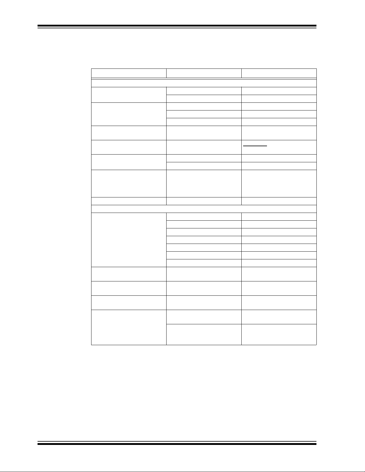
CONVENTIONS USED IN THIS GUIDE
This manual uses the following documentation conventions:
DOCUMENTATION CONVENTIONS
Description Represents Examples
Arial font:
Italic characters Referenced books MPLAB
Emphasized text ...is the only compiler...
Initial caps A window the Output window
A dialog the Settings dialog
A menu selection select Enable Programmer
Quotes A field name in a window or
dialog
Underlined, italic text with
right angle bracket
Bold characters A dialog button Click OK
N‘Rnnnn A number in verilog format,
Text in angle brackets < > A key on the keyboard Press <Enter>, <F1>
Courier New font:
Plain Courier New Sample source code #define START
Italic Courier New A variable argument file.o, where file can be
Square brackets [ ] Optional arguments mcc18 [options] file
Curly brackets and pipe
character: { | }
Ellipses... Replaces repeated text var_name [,
A menu path File>Save
A tab Click the Power tab
where N is the total number of
digits, R is the radix and n is a
digit.
Filenames autoexec.bat
File paths c:\mcc18\h
Keywords _asm, _endasm, static
Command-line options -Opa+, -Opa-
Bit values 0, 1
Constants 0xFF, ‘A’
Choice of mutually exclusive
arguments; an OR selection
Represents code supplied by
user
“Save project before build”
4‘b0010, 2‘hF1
any valid filename
[options]
errorlevel {0|1}
var_name...]
void main (void)
{ ...
}
®
IDE User’s Guide
RECOMMENDED READING
This user's guide describes how to use the PICDEM Lab II Development Board. For the
latest information on using other tools, refer to the MPLAB
www.microchip.com/mplabx/. This resource page contains updated documentation,
downloads and links to other MPLAB X compatible tools, plug-ins and much more.
DS40001814A-page 6 2015 Microchip Technology Inc.
®
X IDE home page:
Page 7

THE MICROCHIP WEB SITE
Microchip provides online support via our web site at www.microchip.com. This web
site is used as a means to make files and information easily available to customers.
Accessible by using your favorite Internet browser, the web site contains the following
information:
• Product Support – Data sheets and errata, application notes and sample
programs, design resources, user’s guides and hardware support documents,
latest software releases and archived software. PICDEM Lab II Development
Board specific product support can be accessed via the product web-page at
www.microchip.com/PICDEMLABII.
• General Technical Support – Frequently Asked Questions (FAQs), technical
support requests, online discussion groups, Microchip consultant program
member listing.
• Additional Labs – Additional lab materials for the PICDEM Lab II Development
Board are available via the PICDEM Lab II Development Board landing page.
These lab materials cover additional hardware applications and labs relating to
new and existing products.
• Business of Microchip – Product selector and ordering guides, latest Microchip
press releases, listing of seminars and events, listings of Microchip sales offices,
distributors and factory representatives
Preface
DEVELOPMENT SYSTEMS CUSTOMER CHANGE NOTIFICATION SERVICE
Microchip’s customer notification service helps keep customers current on Microchip
products. Subscribers will receive e-mail notification whenever there are changes,
updates, revisions or errata related to a specified product family or development tool of
interest.
To register, access the Microchip web site at www.microchip.com, click on Customer
Change Notification and follow the registration instructions.
The Development Systems product group categories are:
• Compilers – The latest information on Microchip C compilers, assemblers, linkers
and other language tools. These include all MPLAB C compilers; all MPLAB
assemblers (including MPASM™ assembler); all MPLAB linkers (including
MPLINK™ object linker); and all MPLAB librarians (including MPLIB™ object
librarian).
• Emulators – The latest information on Microchip in-circuit emulators.This
includes the MPLAB REAL ICE™ and MPLAB ICE 2000 in-circuit emulators.
• In-Circuit Debuggers – The latest information on the Microchip in-circuit
debuggers. This includes MPLAB ICD 3 in-circuit debuggers and PICkit™ 3
debug express.
• MPLAB
Integrated Development Environment for development systems tools. This list is
focused on the MPLAB IDE, MPLAB IDE Project Manager, MPLAB Editor and
MPLAB SIM simulator, as well as general editing and debugging features.
• Programmers – The latest information on Microchip programmers. These include
production programmers such as MPLAB REAL ICE in-circuit emulator, MPLAB
ICD 3 in-circuit debugger and MPLAB PM3 device programmers. Also included
are nonproduction development programmers such as PICSTART
PICkit 2 and 3.
®
IDE – The latest information on Microchip MPLAB IDE, the Windows®
®
Plus and
2015 Microchip Technology Inc. DS40001814A-page 7
Page 8

PICDEM™ Lab II Development Board User’s Guide
CUSTOMER SUPPORT
Users of Microchip products can receive assistance through several channels:
• Distributor or Representative
• Local Sales Office
• Field Application Engineer (FAE)
• Technical Support
Customers should contact their distributor, representative or field application engineer
(FAE) for support. Local sales offices are also available to help customers. A listing of
sales offices and locations is included in the back of this document.
Technical support is available through the web site at:
http://www.microchip.com/support.
REVISION HISTORY
Revision A (August 2015)
Initial release of this document.
DS40001814A-page 8 2015 Microchip Technology Inc.
Page 9

PICDEM™ LAB II DEVELOPMENT
BOARD USER’S GUIDE
Chapter 1. Introduction to PICDEM™ Lab II
The PICDEM Lab II Development Board supports Microchip's 6-, 8-, 14-, 18-, 20-, 28-,
and 40-pin 8-bit PIC
microcontroller sockets offer flexibility of connectivity to all pins on the PIC MCUs. This
board provides flexibility for experimentation through a large solderless development
block, a USB-Serial/I
features a USB mini-B connector, two mikroBUS™ footprints to accommodate a variety
of plug-in Click™ board sensors, and individual ICSP™/ICD connectors for each
microcontroller.
®
MCUs. Dual-row expansion headers on either side of each
2
C interface and external board connectors. Additionally, it
1.1 PICDEM LAB II DEVELOPMENT BOARD KIT CONTENTS
The PICDEM Lab II Development Board kit contains the following (Figure 1-1):
• PICDEM Lab II Development Board
• Out-of-Box Lab Component Kit
• Quick Start Guide
FIGURE 1-1: PICDEM™ LAB II DEVELOPMENT BOARD KIT
2015 Microchip Technology Inc. DS40001814A-page 9
Page 10

PICDEM™ Lab II Development Board User’s Guide
1
2
345 678910
18
19
20
21
22
23 24
17
16
15
14
13
12
11
1. Power connector (GND, GND, +
V
VAR
, +3.3V, +3.3V, +5V, +5V)
2. ICSP™/ICD 28/40-pin microcontroller socket
3. ICSP/ICD 8/14/20-pin microcontroller socket
4. USB™ mini-B socket for USB development
5. ICSP/ICD 18-pin microcontroller socket
6. ICSP/ICD 6-pin microcontroller socket (PIC10FXXX in 8-pin DIP)
7. Communications connector (RX, SCL, SDA, GND, V
DD, TX)
8. USB connector for USB-ASYNC/I
2
C
9. Power switch
10. 9V power supply connector
11. Input voltage select jumpers
12. External supply connection points
13.
V
VAR
adjustment potentiometer
14. mikroBUS™ Click board socket with breakout connectors
15. Power connector (GND, GND, +
V
VAR
, +3.3V, +3.3V, +5V, +5V)
16. Solderless bread board
17. mikroBUS™ Click board socket with breakout connectors
18. 20-pin expansion board connectors for external development boards
19. 16-pin expansion connectors for LCD modules
20. 28-/40-pin microcontroller sockets
21. 8-/14-/20-pin microcontroller socket
22. USB break-out connector
23. 18-pin microcontroller socket
24. 6-pin microcontroller socket (PIC10FXXX in 8-pin DIP)
1.2 PICDEM LAB II DEVELOPMENT BOARD LAYOUT
Figure 1-2 identifies the major features of the PICDEM Lab II Development Board.
FIGURE 1-2: PICDEM™ LAB II DEVELOPMENT BOARD LAYOUT
DS40001814A-page 10 2015 Microchip Technology Inc.
Page 11

1.3 POWER SOURCES
The PICDEM Lab II Development Board can be powered in one of three ways,
depending on its usage.
1.3.1 USB Connector (J18)
The USB connector (J18) will power the entire PICDEM Lab II Development Board.
Shunt jumpers must be placed onto jumpers J2 and J6 (Figure 1-2). Shunt jumpers
connecting the center and right pins of J2 and J6 will connect the internal regulators to
the USB supply on J18. With USB power connected to J18, power LEDs LD1 and LD2
will always be on to indicate that 5V, 3.3V, and V
1.3.2 9V External Power Supply (J1)
The 9V external power supply (J1) will also power the entire PICDEM Lab II
Development Board. Shunt jumpers must be placed onto jumpers J2 and J6
(Figure 1-2). Shunt jumpers connecting the center and top pins of J2 and J6 will
connect the internal regulators to the 9V DC input J1. In this configuration, switch SW1
can be used to turn power to the board on and off. With 9V external power connected
to J1, and switch SW1 in the on position, power LEDs LD1 and LD2 will always be on
to indicate that 5V, 3.3V, and V
1.3.3 External Supply Connection Points
The external supply connections points (TP1-4) will also power the entire PICDEM Lab
II Development Board. Shunt jumpers must be placed onto jumpers J2 and J6
(Figure 1-2). The center and bottom pins of J2 and J6 will connect the 5V and 3.3V
connections to the four external supply connection points (TP1-GND, TP2-5V,
TP3-3.3V, TP4-GND). With 5V and 3.3V connected to the external supply connection
points, power LEDs LD1 and LD2 will always be on to indicate that 5V, 3.3V and V
are available on the board.
are available on the board.
VAR
are available on the board.
VAR
VAR
1.4 CONNECTING THE PICkit™ PROGRAMMER/DEBUGGER
Connections for the PICkit programmer, REAL ICE™ in-circuit emulator or ICD
modules are done through the 6-pin headers above the microcontroller sockets
(Figure 1-2). Each socket group has a separate connector to allow individual
programming of the devices. 28-/40-pin devices are programmed via ICSP4,
8-/14-/20-pin devices are programmed via ICSP3, 18-pin devices are programmed via
ICSP2, and 6-pin PIC10FXXX devices are programmed via ICSP1. The pin to the
furthest right of each ICSP connector has a small white dot that signifies the location of
pin 1. The programmer should be connected to the appropriate ICSP connector with its
pin 1 matching the ICSP connector pin 1. Start-up and programming of any
programmer/in-circuit debugger should be performed as specified by the
programmer/debugger documentation.
2015 Microchip Technology Inc. DS40001814A-page 11
Page 12

PICDEM™ Lab II Development Board User’s Guide
1.5 CONNECTING THE USB I2C/ASYNC COMMUNICATIONS
There are two connections to the on-board USB I2C/ASYNC interface: the first is a USB
mini-B connector J18, and the second is the on-board connector J4. A standard USB
cable should be plugged into J18 and the PC/Apple computer to be used as an
interface. If the driver for the MCP2221 has not been loaded, it should be loaded prior
to connecting to the PICDEM Lab II Development Board. See Section 2.2 for
information concerning the installation of drivers and terminal programs.
To connect to the on-board connector J4, four connections must be made. Pins 2 and
3 of J4 should be connected to V
This will set the high and low voltage outputs for both the I
Pins 1 and 6 of J4 should connect to the Rx and Tx connections, respectively, of the
circuit being developed (pin 1 is Tx out of the interface and pin 6 is Rx into the interface). Alternately, pins 4 and 5 of J4 should connect to SDA and SCL, respectively, of
the circuit being developed. The interface does not provide any pull-up resistors on
either SDA or SCL, so the circuit being developed should include appropriate pull-up
resistors for the I
2
C interface.
1.6 INSTALLING MikroElektronika CLICK™ BOARDS
To install a Click board in the PICDEM Lab II Development Board, orient the Click board
such that pin 1 faces away from the solderless prototyping block, align the Click board
pins with the socket and press the board downward firmly until the pins fully seat in the
sockets.
Connections between the power supply voltages (+5V, +3.3V and GND) and the Click
board sockets are already present. It is left to the user to make connections between
the Click board control interface and the appropriate pins of the microcontroller. The
pinout of the Click boards is included below for reference.
Figure 1-3 lists the connections to the MikroElektronika Click boards.
DD (5V, 3.3V or V
) and VSS of the target circuit.
VAR
2
C and ASYNC interfaces.
FIGURE 1-3: PINOUT SPECIFICATIONS
DS40001814A-page 12 2015 Microchip Technology Inc.
Page 13

1.7 INSTALLING EXPANSION BOARDS AND AN LCD MODULE
Installing an expansion board on the PICDEM Lab II Development Board is very simple,
provided the expansion board uses a single row 0.100” right angle, or vertical header.
Simply push the pins of the header into the horizontal sockets of J8. Power, output and
input pins from the expansion board can then be connected to the on-board circuitry
using the vertical sockets of J8. The pins of the horizontal and vertical sockets of J8 are
connected one-to-one, so any connection made in a horizontal socket will be
connected to the adjacent vertical pin. This combination makes it very simple to
connect to an expansion board without the need for a cumbersome wire connection off
the PICDEM Lab II.
Installing an LCD module is equally easy, provided the LCD module uses a single-row
0.100” right angle, or vertical header. Note a horizontal header is more convenient in
that it allows the LCD module to lay flat next to the PICDEM Lab II. Once installed,
connections to the power, outputs and inputs of the LCD module are the same as for
the expansion board mentioned above.
2015 Microchip Technology Inc. DS40001814A-page 13
Page 14

PICDEM™ Lab II Development Board User’s Guide
NOTES:
DS40001814A-page 14 2015 Microchip Technology Inc.
Page 15

PICDEM™ LAB II DEVELOPMENT
BOARD USER’S GUIDE
Chapter 2. Getting Started
The PICDEM Lab II Development Board must be used with the MPLAB X Integrated
Development Environment (IDE) and either a PICkit™ 3 programmer/debugger,
REAL-ICE in-circuit emulator or ICD3 programmer/debugger. The MPLAB X IDE is
available free on Microchip's web site, www.microchip.com. Use version v3.05 or later.
The PICDEM Lab II Development Board, through MPLAB X and a
programmer/debugger, creates a low-voltage in-circuit debugger as well as a
low-voltage programmer for all supported devices. In-circuit debugging allows the user
to run, examine and modify programs for the supported device embedded in the
PICDEM Lab II hardware. This facilitates the debugging of firmware and hardware
concurrently. Use the PICDEM Lab II Development Board with MPLAB X IDE and a
programmer/debugger to run, stop and single-step through programs – breakpoints
can be set and the processor can be reset. When the processor stops, the contents of
the register are available for examination and modification.
2.1 CONNECTING POWER TO THE PICDEM LAB II
The PICDEM Lab II Development Board can be powered in one of three ways:
•USB
• 9V DC input
• External power supplies.
2.1.1 USB Connector (J18)
To power the PICDEM Lab II via the USB port, connect a USB cable between the USB
mini-B connector J18 and either a PC/Apple computer with a USB connector or a USB
power supply. Shunt jumpers must be placed such that they connect the center and
right pins of J2 and J6 (Figure 1-2). When the jumpers are placed properly and
connected to a USB power source, power LEDs LD1 and LD2 should light, indicating
that 5V, 3.3V and V
are available on the board.
VAR
2.1.2 9V External Power Supply (J1)
To power the PICDEM Lab II via the 9V external power supply, connect a 9V external
power supply to connector J1. Shunt jumpers must be placed such that they connect
the center and top pins of J2 and J6 (Figure 1-2). Next, move the switch SW1 to the on
position. When the jumpers are placed properly, switch SW1 is in the on position and
the board is connected to a powered 9V external power supply, power LEDs LD1 and
LD2 should light, indicating that 5V, 3.3V and V
are available on the board.
VAR
2.1.3 External Supply Connection Points
To power the PICDEM Lab II via the external supply connection points, connect an
external 5V power supply to TP1 and TP2 (TP1-GND, TP2-5V), then connect an
external 3.3V power supply to TP3 and TP4 (TP3-3.3V, TP4-GND). Shunt jumpers
must be placed such that they connect the center and bottom pins of J2 and J6
(Figure 1-2). When the jumpers are placed properly and the external power supplies
are powered, power LEDs LD1 and LD2 should light, indicating that 5V, 3.3V and V
are available on the board.
VAR
2015 Microchip Technology Inc. DS40001814A-page 15
Page 16

PICDEM™ Lab II Development Board User’s Guide
Note: V
is generated from the 5V input in all power supply modes of operation.
VAR
Adjustment of V
clockwise rotation of the potentiometer will result in approximately 1.5V,
and full counterclockwise rotation will result in approximately 4.8V.
is via potentiometer R7 (see item 13 in Figure 1-2). Full
VAR
2.2 CONNECTING A PROGRAMMER/IN-CIRCUIT DEBUGGER
To connect either a programmer, REAL ICE in-circuit emulator or PICkit 3 programmer
to the PICDEM Lab II, first, select the package size required for the microcontroller and
load the device in the appropriate socket (see items 20, 21, 23, or 24 in Figure 1-2).
Next, connect the 6-pin programming connector to the corresponding ICSP/ICD
header on the PICDEM Lab II (see items 2, 3, 5, or 6). Note that pin 1 of the ICSP/ICD
connectors is labeled by a small white dot on the silk screen of the board. Once the
programmer/debugger is connected, connect power to the board (see Section 2.1),
run MPLAB X, and follow the instructions listed in the MPLAB X IDE User’s Guide
(DS50002027) for loading, compiling and programming code into an 8-bit
microcontroller.
2.3 LOADING DRIVERS AND TERMINAL PROGRAMS FOR THE USB-ASYNC/I2C
INTERFACE
Download the driver package from Microchip’s MCP2221 web page (Figure 2-1).
FIGURE 2-1: MCP2221 DRIVER DOWNLOAD
Unzip the file and double click on the MchpCdcDriverInstallationTool.exe
icon (Figure 2-1).
DS40001814A-page 16 2015 Microchip Technology Inc.
Page 17

FIGURE 2-2: MCP2221 DRIVER UNZIP
Finally, follow the direction of the installation tool until finished. At this point, the driver
for the asynchronous serial port will be leaded and ready for use. Any asynchronous
serial port terminal program can now be used. Select the Com port corresponding to
the MCP2221 and configure the baud rate, Stop bits, and parity as necessary for the
application.
To install the Microchip MCP2221 I
2
C/SMBus terminal program installation package
(Figure 2-3) from Microchip’s MCP2221 web page, follow the steps below.
FIGURE 2-3: MCP2221 I
2
C/SMBus TERMINAL DOWNLOAD
2015 Microchip Technology Inc. DS40001814A-page 17
Page 18

PICDEM™ Lab II Development Board User’s Guide
Unzip and double click on the MCP2221 terminal installer program (Figure 2-4).
FIGURE 2-4: MCP2221 I
2
C/SMBus TERMINAL UNZIP
DS40001814A-page 18 2015 Microchip Technology Inc.
Page 19

Finally, follow the direction of the installation tool until finished. At this point, the
1. SAVE: This button will save the current set of commands to a .cvs file.
2. PROTOCOL: This pull-down box is used to select I
2
C.
3. ADDRESS LENGTH: This box is used to select 7- or 10-bit addressing.
4. ADDRESS: This box is used to select the address to the device.
5. OPERATION: This box is used to select Read/Write/Set V
REF.
6. IMPORT: This button will allow the importation of a set of commands.
7. DATA: For writes, this is the data to be sent. For reads, this is the count.
8. RECEIVED/SENT DATA: This window shows the results of a command, all read and
written data will appear here with a green OK if command was successful.
9. SEND: This button will execute the adjacent command.
10. SPEED: This window is used to select the bus speed 100/400 kb/s.
11. SELECT DEVICE: This window selects the MCP2221 required for communications. If
only one device is on the system, then only one option will appear.
1
23
4
5
6
7
8
9
10
11
Terminal program is ready for use – just double click to open. The Terminal program
should appear as in Figure 2-5.
FIGURE 2-5: MCP2221 I
2
C/SMBus TERMINAL WINDOW
2015 Microchip Technology Inc. DS40001814A-page 19
Page 20

PICDEM™ Lab II Development Board User’s Guide
2.4 LOADING MPLAB X IDE AND THE XC COMPILER
The MPLAB X IDE and XC8/16/32 compilers can be downloaded from the Microchip
web page under the heading of Design Support. While the IDE is free to download, the
XC8/16/32 compilers require a licensing fee for the professional version. A short term
evaluation version is available, as well as a student version. To download the IDE
and/or the compilers, go to the Design Support tab on the web site and click on the
MPLAB X IDE option (Figure 2-6).
FIGURE 2-6: DESIGN SUPPORT
Then click on the MPLAB X IDE Downloads option on the left-hand side of the screen
(Figure 2-7).
FIGURE 2-7: MPLAB
®
X IDE DOWNLOAD
DS40001814A-page 20 2015 Microchip Technology Inc.
Page 21

Finally, select the appropriate operating system for the computer (Figure 2-8).
FIGURE 2-8: MPLAB X IDE DOWNLOAD SELECTION
Once the file is downloaded, double click on the file and follow the installation
instructions provided with the install packages. If unfamiliar with MLAB X, there are
several webinars available to help getting started (Figure 2-9).
FIGURE 2-9: MPLAB
®
X IDE RELATED VIDEOS
Note: The MPLAB® X installation will prompt the user about installing the XC
compilers as part of its install. Click Yes at the prompt, and copies of the XC
compilers will be downloaded and installed.
2015 Microchip Technology Inc. DS40001814A-page 21
Page 22

PICDEM™ Lab II Development Board User’s Guide
2.5 LOADING MCC INTO MPLAB X
MCC can be downloaded within the MPLAB X IDE by selecting the Tools tab at the top
of the window and then selecting Plugins from the resulting drop-down window
(Figure 2-10).
FIGURE 2-10: LOADING MCC INTO MPLAB
When the Plugins window appears, click on the table for Available Plugins and select
MCC from the list of options and click on the Install button at the bottom left of the
window. The IDE will then download and install the MCC within MPLAB X.
To open MCC within MPLAB X, select the Tools window, select the Embedded tab, and
then click on the MPLAB Code Configurator option.
®
X
FIGURE 2-11: STARTING MCC IN MPLAB
For additional information on the operation of the MCC refer to the training materials
available on the Microchip website.
®
X
DS40001814A-page 22 2015 Microchip Technology Inc.
Page 23

Chapter 3. Where to Find the Lab Documentation
3.1 OUT-OF-THE-BOX LABS
The out-of-the-box labs can be downloaded from the Microchip web page under the
PICDEM Lab II product page.
FIGURE 3-1: OUT-OF-THE-BOX LABS
PICDEM™ LAB II DEVELOPMENT
BOARD USER’S GUIDE
The four labs that use the included components are:
1. Hello world embedded lab: This lab is an introductory lab to make the user
acquainted with operation of the PICDEM Lab II and the development tool suite.
It uses a string of LEDs to produce a moving light. If the user presses a button
while either end LED is lit, the direction of the moving light will change. This lab
teaches basic tool operation such as editing, compiling and programming.
2. Power conversion lab 1: This lab introduces the use of microcontrollers to
convert power from one voltage to another. The lab consists of two circuits: a
Villard Multiplier which uses switched capacitors to produce a larger output
voltage, and a Hysteretic Voltage mode inductive boost power supply. The
inductive boost also uses voltage feedback to regulate its output. This lab
teaches the basics of core independent peripherals and basic power conversion.
3. IR remote control lab: This lab uses two microcontrollers: one to create an IR
remote control transmitter with four buttons, and the second to implement an IR
remote control receiver with three LEDS. The transmitter generates an on/off
keying coded signal that the receiver decodes. This lab teaches the use of the
Data Signal Modulator and PWM peripherals in the transmitter and T1G of
Timer1 in the receiver.
2015 Microchip Technology Inc. DS40001814A-page 23
Page 24

PICDEM™ Lab II Development Board User’s Guide
4. Class D audio amplifier lab: This lab retrieves sound wave table information
from a serial EEPROM and uses a Class D audio amplifier configuration to drive
a small speaker. The retrieval of the wave table utilizes the I
MSSP peripheral. The reconstruction of the audio signal uses the 10-bit DAC,
and the class D amplifier uses the programmable ramp generator to create a
triangle wave and a voltage comparator to turn the audio signal into a
proportional PWM driver for the speaker.
3.2 ADDITIONAL LABS
As new labs are developed, additional labs will be added to the code list on the web
page for the PICDEM Lab II.
FIGURE 3-2: ADDITIONAL LABS
2
C capability of the
The labs will be organized by the processor used in the lab, and will be grouped with
other labs using the same microcontroller. In the event that multiple microcontrollers
can support a given lab, the lab will be modified for the additional microcontrollers and
included in the zip file download for the microcontrollers.
3.3 OBTAINING LAB COMPONENTS
For each of the additional labs, a bill of materials is included which specifies the
components used in the lab, the source for the components, and any specifications
necessary for obtaining the components. Where possible, the vendor’s part number is
included to assist in the acquisition of the components.
DS40001814A-page 24 2015 Microchip Technology Inc.
Page 25

PICDEM™ LAB II DEVELOPMENT
Chapter 4. Troubleshooting
4.1 THE BOARD WILL NOT POWER-UP
• If the power indicator LEDs LD1 and LD2 do not light:
- Verify power is connected to the board.
- If the 9V input is used, verify the switch SW1 is in the on position.
- Verify the jumpers on J2 and J6 are placed correctly.
- Verify the 3.3V and 5.0V outputs are not shorted to GND.
• If only one of the power indicator LEDs does not light:
- Verify the jumpers on J2 and J6 are placed correctly.
- Verify that the missing voltage output is not shorted to GND.
• If both power indicator LEDs light but V
- Verify that the V
- Verify the voltage adjustment potentiometer R7 is not broken.
For all other problems, consult Microchip’s online help system.
voltage output is not shorted to GND.
VAR
BOARD USER’S GUIDE
is missing:
VAR
4.2 THE MICROCONTROLLER WILL NOT PROGRAM/DEBUG
• If the programmer does not recognize the microcontroller:
- Verify that the version of MPLAB X IDE loaded on the computer is yellow/green lighted for the microcontroller; if not, download the latest version.
- Verify that the programmer/debugger is yellow/green lighted for the
microcontroller; if not, download the latest version of the MPLAB X IDE.
- Verify the programmer/debugger is plugged into the correct ICSP connector
with the correct orientation.
- Verify the programmer/debugger is connected to a working USB port on the
computer.
- Verify power is present on the PICDEM™ Lab II Development Board.
- Verify voltage is supplied to all V
- Verify the ICSP connections to the microcontroller are not loaded by external
circuitry. See the documentation for the programmer/debugger.
- Verify the MPLAB X IDE recognizes the programmer/debugger; if not, consult
the MPLAB X IDE documentation for corrective actions.
• If the programmer recognizes the microcontroller but will not program the device:
- Perform a bulk erase of the microcontroller.
- Verify the low-voltage programming fuse in the Configuration Word is disabled
in the code.
- If the problem persists, contact Microchip concerning the replacement of the
microcontroller.
For all other problems, or if the problem persists, contact Microchip’s help line for
further assistance.
DD pins of the microcontroller.
2015 Microchip Technology Inc. DS40001814A-page 25
Page 26

PICDEM™ Lab II Development Board User’s Guide
4.3 SERIAL/I2C COMMUNICATIONS DO NOT WORK
• If the PICDEM Lab II serial interface is not recognized by the ASYNC terminal
program:
- Verify that the serial driver for the MCP2221 is correctly loaded.
- Verify the USB interface cable is firmly seated in the PICDEM Lab II board.
- Verify the USB interface cable is firmly seated in the USB port of the
computer.
- Verify the USB port used is working.
- Verify that power and GND are connected to pins 2 and 3 of J4 and that
voltage is present at the connector.
If the problem persists, contact Microchip’s help line for further assistance.
• If the PICDEM Lab II serial interface is not recognized by the I
program:
- Verify that the I
- Verify the USB interface cable is firmly seated in the PICDEM Lab II board.
- Verify the USB interface cable is firmly seated in the USB port of the
computer.
- Verify the USB port used is working.
- Verify that power and GND are connected to pins 2 and 3 of J4 and that
voltage is present at the connector.
- Verify pull-up resistors are present on the SDA and SCL (pins 4 and 5) lines of J4.
If the problem persists, contact Microchip’s help line for further assistance.
2
C/SMBus terminal program is correctly loaded.
2
C/SMBus terminal
DS40001814A-page 26 2015 Microchip Technology Inc.
Page 27

PICDEM™ LAB II DEVELOPMENT
1
1
2
2
3
3
4
4
5
5
6
6
D D
C C
B B
A A
* of *
PICdem Lab 2
11/25/2014 9:48:30 AM
219-0544.SchDoc
Project Title
Sch #: Date:
File:
Revision: Sheet
Designed with
Drawn By:
219-0544
Sheet Title
**
Engineer:
219-0544
03-219-0544
ProjectRevisionSCH
Size
B
219-0544
PartNumber:
Altium.com
REV ECO# DESCRIPTION DATE
231
POWER 2.5mm
J1
MCP16311T-E/MS
FB
1
VCC2EN3VIN
4
PGND
5
BOOST
7
SW
6
AGND
8
U6
MCP16311T-E/MS
FB
1
VCC2EN3VIN
4
PGND
5
BOOST
7
SW
6
AGND
8
U7
ADJ
4
VOUT
5
SHDN3Vin1GND
2
U9
TC1187
22µH
L1
15µH
L2
10k
1%
R4
10k
1%
R6
52.3k 1%
R3
10uF
C2
10uFC310uF
25V
0805
C4
10uF
25V
C6
10uF
25V
C7
10uF
25V
C10
10uF
25V
C11
±0.1%31.2k
R5
1uF
16V
C8
1uF
16V
C12
0.1uF
C5
0.1uF
C9
0.1uF
16V
C13
0.1uF
16V
C14
1uF
16V
C15
SGND
SGND
SGND
SGND
SGND
SGND
SGND SGND
SGNDSGND
SGND
SGNDSGND
SGND
SGND SGND
SGND
SGND
SGND
SGND
2.7k
1%
R8
2
1 3
10k
3386F
10%
R7
+5V
Vusb5 Vusb3
+Vvar
1
HDR-2.54 Male 1x1
J3
Vusb5
123
HDR-2.54 Male 1x3
J2
+5V
1
HDR-2.54 Male 1x1
J7
123
HDR-2.54 Male 1x3
J6
+3.3VVusb3
+5Vext
+3.3Vext
TP LOOP Red
TP1
TP LOOP Red
TP3
TP LOOP Black TH
TP2
TP LOOP Black TH
TP4
SGND
SGND
1234567
J5
+5V
+3.3V
+Vvar
SGND
1234567
J8
+5V
+3.3V
+Vvar
SGND
12345678910111213141516171819
20
J9
mikroBUS
7
4
1
8
635
2
10
13
16
9
111412
15
GNDGND
+5V+3.3V
SDA
SCL
TX
RX
INT
PWMAN
RSTCSSCK
MISO
MOSI
J35
mikroBUS
7
4
1
8
635
2
10
13
16
9
111412
15
GNDGND
+5V+3.3V
SDA
SCL
TX
RX
INT
PWMAN
RSTCSSCK
MISO
MOSI
No Load
J32
DNP
SGND SGND
VDD1GP02GP13RST4UART RX5UART TX6GP2
7
GP3
8
SDA
9
SCL
10
VUSB
11
D-
12
D+
13
VSS
14
MCP2221
U12
USB_P
USB_N
2.2k
R2
2.2k
R16
10k
R1
UART_TX
UART_RX
0.47uF
6.3V
0603
C1
U12_SDA
U12_SCL
U12_SDA
U12_SCL
GP0
GP1
GP2 GP3
12345
6
J4
UART_RX
UART_TX
SDA
SCL
USB MINI-B Female
ID
4
VBUS
1
GND
5
D-
2
D+
3
0
J18
USB_P
USB_N
SGND
SGND
SGND
SGND
RESET
Vusb5
123456789
1011121314151617181920
J10
Vusb5
1234567
8
J27
1234567
8
J26
1234567
8
J25
1234567
8
J24
GND
1
VIN
3
VOUT
2
MCP1702-3302E/CB
U8
+3.3V +5V
+3.3V
+5V
SGNDSGND
+5V
DIR
5
A
3
B4GND
2
VCCA
1
VCCB
6
SN74LVC1T45DCKR
U10
DIR
5
A
3
B4GND
2
VCCA
1
VCCB
6
SN74LVC1T45DCKR
U11
0.1uF
C17
0.1uF
C16
0.1uF
C18
0.1uF
C19
U12_TX
U12_RX
SGND
SGND
SGND
SGND
Vusb3 VDUT
VDUT
U12_TX
U12_RX
Vusb3 VDUT
PCA9306D,118
Vref1
2
Vref2
7
SCL1
3
SCL2
6
SDA1
4
SDA2
5
EN
8
GND
1
U13
U12_SCL
U12_SDA
0.1uF
C27
0.1uF
C26
VDUT
SGND
SDA
SCL
SGND
200k
R9
BOARD USER’S GUIDE
Appendix A. Schematics
FIGURE A-1: PICDEM™ LAB II DEVELOPMENT BOARD SCHEMATIC 1
2015 Microchip Technology Inc. DS40001814A-page 27
Page 28

PICDEM™ Lab II Development Board User’s Guide
1
1
2
2
3
3
4
4
5
5
6
6
D D
C C
B B
A A
* of *
PICdem Lab 2
11/25/2014 9:48:47 AM
219-0544 Sheet 2.SchDoc
Project Title
Sch #: Date:
File:
Revision: Sh eet
Designed with
Drawn By:
219-0544
Sheet Title
**
Engineer:
219-0544
03-219-0544
ProjectRevisionSCH
Size
B
219-0544
PartNumber:
Altium.com
45678
9
10
16
1514
131211
17
123
1918202122232425262728
110-91-328-41-001
U4
45678
9
10161514131211
17
123
191820 21
22232425262728293031323334353637383940
110-93-640-41-001050
U5
45678
9
10
1615141312
11
17
123
191820
110-91-320-41-001
U3
RA0
RA1
RA2
RA3
RA4
RA5
RA6
RA7
RB0
RB1
RB2
RB3
RB4
RB5
ICSPCLK4
ICSPDAT4
RC0
RC1
RC2
RC3 RC4
RC5
RC6
RC7
VPP4
RA0
RA1
RA2
RA3
RA4
RA5
RB0
RB1
RB2
RB3
RB4
RB5
ICSPCLK4
ICSPDAT4
RC0
RC1
RC2
RC3 RC4
RC5
RC6
RC7
RD0
RD1 RD2
RD3
RD4
RD5
RD6
RD7
RE0
RE1
RE2
VPP4
RA6
RA7
VDD4
VDD4
0.1uF
25V
0603
C20
SGND
45678
9 10
1615141312
11
17
123
18
110-99-318-41-001
U2
2
3 4
5 6
7 8
9 10
11 12
13 14
15 16117 18
19 20
J20
2
3 4
5 6
7 8
9 10
11 12
13 14
15 16117 18
19 20
J19
2
3 4
5 6
7 8
9 10
11 12
13 14
15 16117 18
J15
2
3 4
5 6
7 8
9 10
11 12
13 14
15 16117 18
J14
PIC10F200-I/P
VDD2VSS7GP3/MCLR/VPP
8
GP0/ICSPDAT/CIN+
5
GP1/ICSPCLK/CIN-
4
GP2/T0CKI/COUT/FOSC4
3
U1
1 2
3 4
5 6
7 8
J13
1 2
3 4
5 6
7 8
J12
ICSPCLK1
U1_GP2
VPP1
ICSPDAT1
U1_GP2
VPP1
1 2
3 4
5 6
7 8
9 10
11 12
13 14
15 16
17 18
19 20
21 22
23 24
25 26
27 28
29 30
31 32
33 34
35 36
37 38
39 40
J21
1 2
3 4
5 6
7 8
9 10
11 12
13 14
15 16
17 18
19 20
21 22
23 24
25 26
27 28
29 30
31 32
33 34
35 36
37 38
39 40
J23
RB0
RB1
RB2
RB3
RB4
RB5
RC4
RC5
RC6
RC7
RD2
RD3
RD4
RD5
RD6
RD7
VDD4 VDD4
RA0
RA1
RA2
RA3
RA4
RA5
RC0
RC1
RC2
RC3
RD0
RD1
RE0
RE1
RE2
VPP4
RA6
RA7
0.1uF
25V
0603
C21
SGND
0.1uF
25V
0603
C22
SGND
0.1uF
25V
0603
C23
SGND
0.1uF
25V
0603
C24
SGND
0.1uF
25V
0603
C25
SGND
VDD1
VDD2
VDD3
VDD4
VDD4
VDD3
SGND
VDD1
VDD2
VDD1VDD1
ICSPCLK2
ICSPCLK3
ICSPCLK4
ICSPCLK1
ICSPCLK1
U1_GP2
ICSPDAT1
ICSPDAT2
ICSPDAT3
ICSPDAT4
12345
6
HDR-2.54 Male 1x6
ICSP1
VDD1
VPP1
ICSPCLK1
ICSPDAT1
SGND
12345
6
HDR-2.54 Male 1x6
ICSP2
VPP2
VDD2
ICSPDAT2
ICSPCLK2
SGND
12345
6
HDR-2.54 Male 1x6
ICSP3
VPP3
VDD3
ICSPDAT3
ICSPCLK3
SGND
12345
6
HDR-2.54 Male 1x6
ICSP4
VPP4
VDD4
ICSPDAT4
ICSPCLK4
SGND
ICSPDAT2
ICSPCLK2
VPP2
U2_RA0
U2_RA1U2_RA2
U2_RA3
U2_RA4
U2_RB0
U2_RB1
U2_RB2
U2_RB3 U2_RB4
U2_RB5
VPP2
U2_RA2
U2_RA3
U2_RA4
U2_RB0
U2_RB1
U2_RB2
U2_RB3
U2_RA6
U2_RA7
U2_RB4
U2_RB5
U2_RA0
U2_RA1
U2_RA6
U2_RA7
ICSPDAT3
ICSPCLK3
U3_RB4
U3_RB5
U3_RB6U3_RB7
U3_RC0
U3_RC1
U3_RC2U3_RC3
U3_RC4
U3_RC5
U3_RA2VPP3
U3_RA4
U3_RA5
U3_RB4
U3_RB5
U3_RB6
U3_RC0
U3_RC1
U3_RC2
U3_RA2
U3_RC6
U3_RC7
U3_RA5
U3_RB7
U3_RC3
U3_RC4
U3_RC5
VPP3
U3_RA4
U3_RC6
U3_RC7
SGND
SGND
SGND
SGND
SGND
SGND
SGND
SGND
VPP1
FIGURE A-2: PICDEM™ LAB II DEVELOPMENT BOARD SCHEMATIC 2
DS40001814A-page 28 2015 Microchip Technology Inc.
Page 29

Worldwide Sales and Service
AMERICAS
Corporate Office
2355 West Chandler Blvd.
Chandler, AZ 85224-6199
Tel: 480-792-7200
Fax: 480-792-7277
Technical Support:
http://www.microchip.com/
support
Web Address:
www.microchip.com
Atlanta
Duluth, GA
Tel: 678-957-9614
Fax: 678-957-1455
Austin, TX
Tel: 512-257-3370
Boston
Westborough, MA
Tel: 774-760-0087
Fax: 774-760-0088
Chicago
Itasca, IL
Tel: 630-285-0071
Fax: 630-285-0075
Cleveland
Independence, OH
Tel: 216-447-0464
Fax: 216-447-0643
Dallas
Addison, TX
Tel: 972-818-7423
Fax: 972-818-2924
Detroit
Novi, MI
Tel: 248-848-4000
Houston, TX
Tel: 281-894-5983
Indianapolis
Noblesville, IN
Tel: 317-773-8323
Fax: 317-773-5453
Los Angeles
Mission Viejo, CA
Tel: 949-462-9523
Fax: 949-462-9608
New York, NY
Tel: 631-435-6000
San Jose, CA
Tel: 408-735-9110
Canada - Toronto
Tel: 905-673-0699
Fax: 905-673-6509
ASIA/PACIFIC
Asia Pacific Office
Suites 3707-14, 37th Floor
Tower 6, The Gateway
Harbour City, Kowloon
Hong Kong
Tel: 852-2943-5100
Fax: 852-2401-3431
Australia - Sydney
Tel: 61-2-9868-6733
Fax: 61-2-9868-6755
China - Beijing
Tel: 86-10-8569-7000
Fax: 86-10-8528-2104
China - Chengdu
Tel: 86-28-8665-5511
Fax: 86-28-8665-7889
China - Chongqing
Tel: 86-23-8980-9588
Fax: 86-23-8980-9500
China - Dongguan
Tel: 86-769-8702-9880
China - Hangzhou
Tel: 86-571-8792-8115
Fax: 86-571-8792-8116
China - Hong Kong SAR
Tel: 852-2943-5100
Fax: 852-2401-3431
China - Nanjing
Tel: 86-25-8473-2460
Fax: 86-25-8473-2470
China - Qingdao
Tel: 86-532-8502-7355
Fax: 86-532-8502-7205
China - Shanghai
Tel: 86-21-5407-5533
Fax: 86-21-5407-5066
China - Shenyang
Tel: 86-24-2334-2829
Fax: 86-24-2334-2393
China - Shenzhen
Tel: 86-755-8864-2200
Fax: 86-755-8203-1760
China - Wuhan
Tel: 86-27-5980-5300
Fax: 86-27-5980-5118
China - Xian
Tel: 86-29-8833-7252
Fax: 86-29-8833-7256
ASIA/PACIFIC
China - Xiamen
Tel: 86-592-2388138
Fax: 86-592-2388130
China - Zhuhai
Tel: 86-756-3210040
Fax: 86-756-3210049
India - Bangalore
Tel: 91-80-3090-4444
Fax: 91-80-3090-4123
India - New Delhi
Tel: 91-11-4160-8631
Fax: 91-11-4160-8632
India - Pune
Tel: 91-20-3019-1500
Japan - Osaka
Tel: 81-6-6152-7160
Fax: 81-6-6152-9310
Japan - Tokyo
Tel: 81-3-6880- 3770
Fax: 81-3-6880-3771
Korea - Daegu
Tel: 82-53-744-4301
Fax: 82-53-744-4302
Korea - Seoul
Tel: 82-2-554-7200
Fax: 82-2-558-5932 or
82-2-558-5934
Malaysia - Kuala Lumpur
Tel: 60-3-6201-9857
Fax: 60-3-6201-9859
Malaysia - Penang
Tel: 60-4-227-8870
Fax: 60-4-227-4068
Philippines - Manila
Tel: 63-2-634-9065
Fax: 63-2-634-9069
Singapore
Tel: 65-6334-8870
Fax: 65-6334-8850
Taiwan - Hsin Chu
Tel: 886-3-5778-366
Fax: 886-3-5770-955
Taiwan - Kaohsiung
Tel: 886-7-213-7828
Taiwan - Taipei
Tel: 886-2-2508-8600
Fax: 886-2-2508-0102
Thailand - Bangkok
Tel: 66-2-694-1351
Fax: 66-2-694-1350
EUROPE
Austria - Wels
Tel: 43-7242-2244-39
Fax: 43-7242-2244-393
Denmark - Copenhagen
Tel: 45-4450-2828
Fax: 45-4485-2829
France - Paris
Tel: 33-1-69-53-63-20
Fax: 33-1-69-30-90-79
Germany - Dusseldorf
Tel: 49-2129-3766400
Germany - Karlsruhe
Tel: 49-721-625370
Germany - Munich
Tel: 49-89-627-144-0
Fax: 49-89-627-144-44
Italy - Milan
Tel: 39-0331-742611
Fax: 39-0331-466781
Italy - Venice
Tel: 39-049-7625286
Netherlands - Drunen
Tel: 31-416-690399
Fax: 31-416-690340
Poland - Warsaw
Tel: 48-22-3325737
Spain - Madrid
Tel: 34-91-708-08-90
Fax: 34-91-708-08-91
Sweden - Stockholm
Tel: 46-8-5090-4654
UK - Wokingham
Tel: 44-118-921-5800
Fax: 44-118-921-5820
07/14/15
2015 Microchip Technology Inc. DS40001814A-page 29
 Loading...