

Page 1
Parrot Hardware
Parrot (Voice Recorder) with ATtiny817 Hardware User's
Guide
Introduction
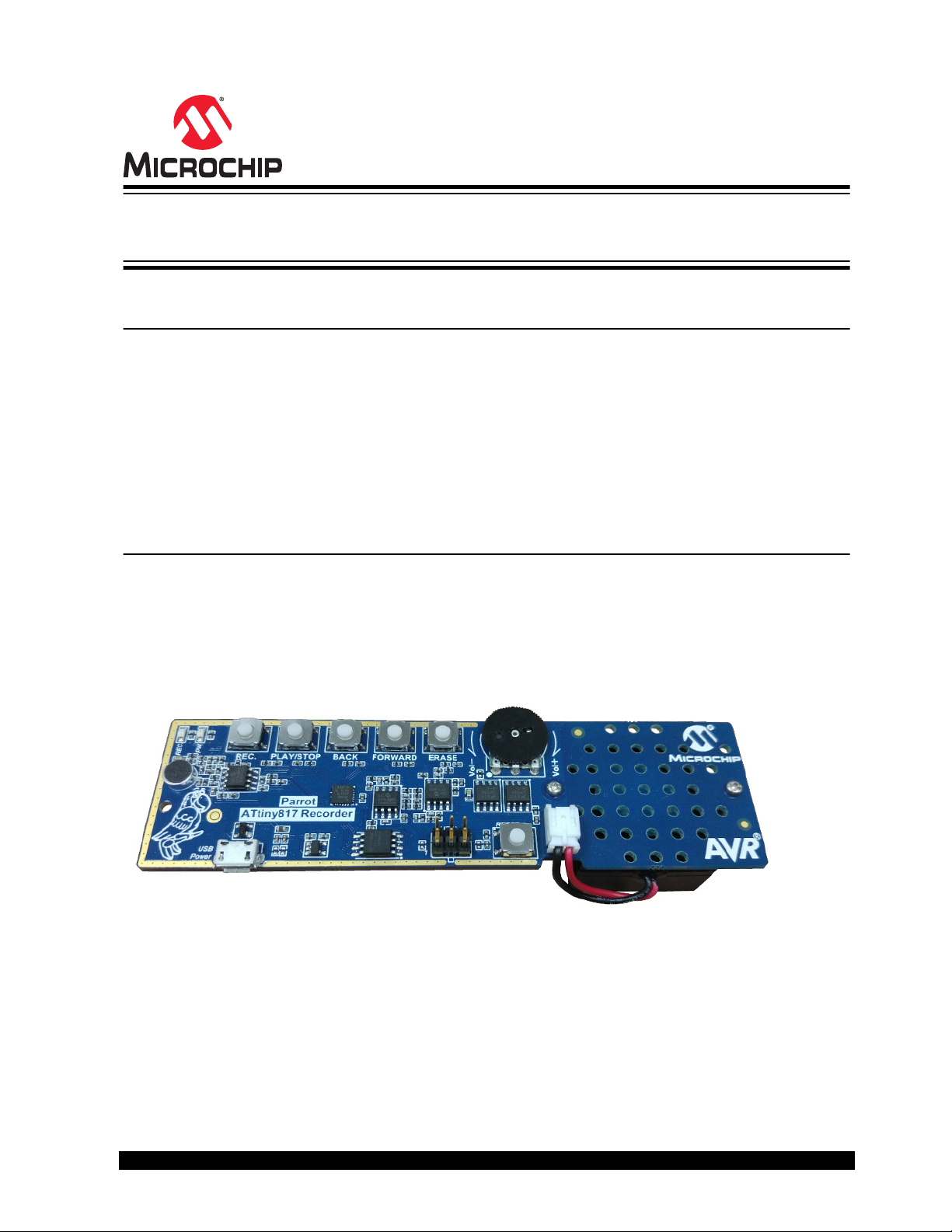
This user guide describes an audio demo board based on the ATtiny817, a high-performance tinyAVR® 8bit microcontroller.
The Parrot field engagement board can be used as a voice recorder to record, play back, browse, and
erase voice data. This application helps the user to quickly evaluate the ADC and DAC features of the
microcontroller.
The firmware and accompanying application note ( AVR42777) is available on Atmel START http://
start.atmel.com/.
Features
• Voice Record and Playback
• Electret Microphone
• Volume Control
• 8Mb SPI Data Flash
• Single-Wire Programming via UPDI
© 2017 Microchip Technology Inc.
User Guide
DS40001916A-page 1
Page 2

Parrot Hardware
Table of Contents
Introduction......................................................................................................................1
Features.......................................................................................................................... 1
1. Block Diagram........................................................................................................... 3
2. Hardware Details....................................................................................................... 4
2.1. Microphone...................................................................................................................................4
2.2. Filter for ADC................................................................................................................................4
2.3. Microcontroller..............................................................................................................................5
2.3.1. ADC............................................................................................................................... 6
2.3.2. DAC............................................................................................................................... 6
2.4. Filter for DAC................................................................................................................................7
2.5. Power Amplifier............................................................................................................................ 8
2.6. User Interfaces............................................................................................................................. 9
2.6.1. Buttons...........................................................................................................................9
2.6.2. LEDs..............................................................................................................................9
2.7. External Data Flash....................................................................................................................10
2.8. UPDI Programming Interface..................................................................................................... 10
3. Firmware Programming........................................................................................... 12
3.1. Connection................................................................................................................................. 12
3.2. Firmware.................................................................................................................................... 12
3.3. Programming..............................................................................................................................12
4. Revision History.......................................................................................................14
5. Object of Declaration............................................................................................... 15
The Microchip Web Site................................................................................................ 16
Customer Change Notification Service..........................................................................16
Customer Support......................................................................................................... 16
Microchip Devices Code Protection Feature................................................................. 16
Legal Notice...................................................................................................................17
Trademarks................................................................................................................... 17
Quality Management System Certified by DNV.............................................................18
Worldwide Sales and Service........................................................................................19
© 2017 Microchip Technology Inc.
User Guide
DS40001916A-page 2
Page 3

1. Block Diagram
ATtiny817
DACADC
SPI
Data Flash
OP
AMP
Filter
Power
AMP
REC PLAY/STOP BACK FORWARD
GPIO x6
PWR REC
GPIO x2
5V
3.3V
Volume
Control
ERASE
LDO
3.3V
User
The Parrot field engagement board demonstrates the capabilities of the ATtiny817 with audio processing,
using its ADC and DAC peripherals. It is possible to record, playback, erase, rewind, and fast forward by
using the buttons.
Parrot Hardware
As shown in the figure above, once the “REC” (record) button is pressed, the electret microphone starts
to detect an analog sound signal. The sound signal will be processed in the front-end operation amplifier
and a low-pass filter will be applied to the signal. The signal will then be digitized by the ADC of the
ATtiny817 microcontroller. The converted sound data is stored in the external data Flash through the SPI
interface. When the button is pressed again, this recording process is stopped.
Once the “PLAY/STOP” button is pressed, the sound data stored in the data Flash is read and converted
to an analog signal through the DAC on the MCU. The analog signal is then sent through a low-pass filter
before it is sent to the amplifier with the set volume. This allows the user to listen to the previously
recorded sound. If the button is pressed again, the play process is stopped.
The board is supplied with +5V from the Micro-USB interface with ESD protection. The applied LDO can
source out 150mA @ 3.3V system power.
Figure 1-1. Parrot Board
© 2017 Microchip Technology Inc.
User Guide
DS40001916A-page 3
Page 4
2. Hardware Details
1uF
C19
10k
R21
VCC_P3V3
SGND
TP5
BL-MP6022P-2C-44DB
1
2
G
GND
S
D
Microphone
MIC1
SGND
3.3nF
C20
SGND
C17
4.7uF
100k
R18
100nF
C15
2k
R19
SGND
39k
R20
24k
R26
VCC_P3V3
ADC_VF_HALF
18k
R40
1uF
C18
2.1 Microphone
The device is a general low-cost electret microphone. See the table below for technical parameters.
It is highly recommended to keep the microphone at least 10cm away from the sound source to avoid
peak clipping or distortion of the signal.
Table 2-1. Microphone Parameters
Parameters Value
Manufacturer part number BL-MP6022P-2C-44DB
Standard operation voltage (DC) 2V
Active current <0.5mA
Sensitivity (1kHz, 0dB=1V/Pa) -44dB ±3dB
S/N ratio 58dB
Parrot Hardware
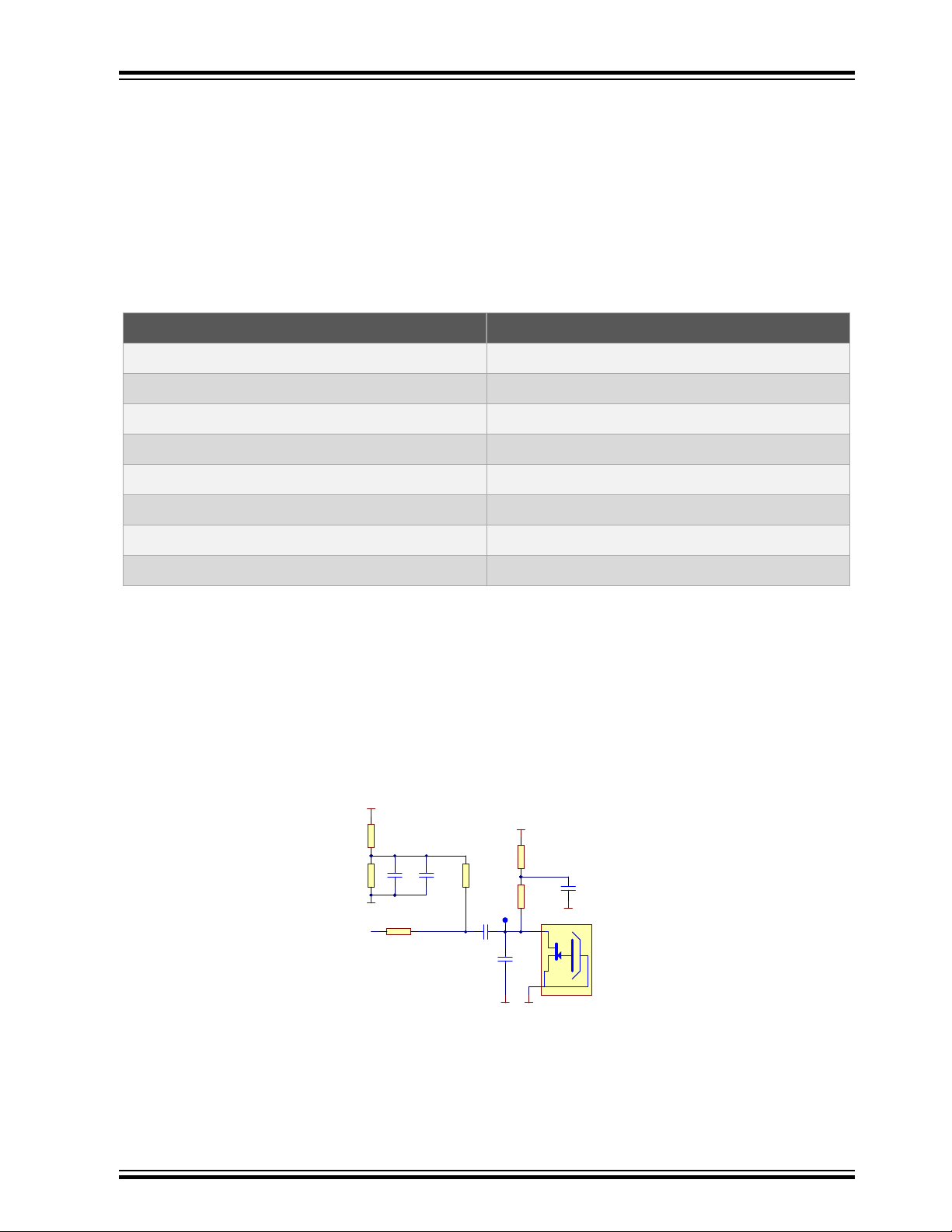
2.2 Filter for ADC
As shown in the figure below, the power for the microphone is VCC_P3V3, which is filtered by a low-pass
filter to reduce noise from the power supply.
Typically, the original voice signal is quite weak, with measured amplitude around 10mV (less than
50mV). So the signal must be amplified and filtered accordingly. To make sure that the signal can be
amplified without being distorted, a voltage offset is required.
Figure 2-1. Microphone Circuit
Impedance < 2.2kΩ
Frequency (Hz) 20-16,000
Directivity Omnidirectional
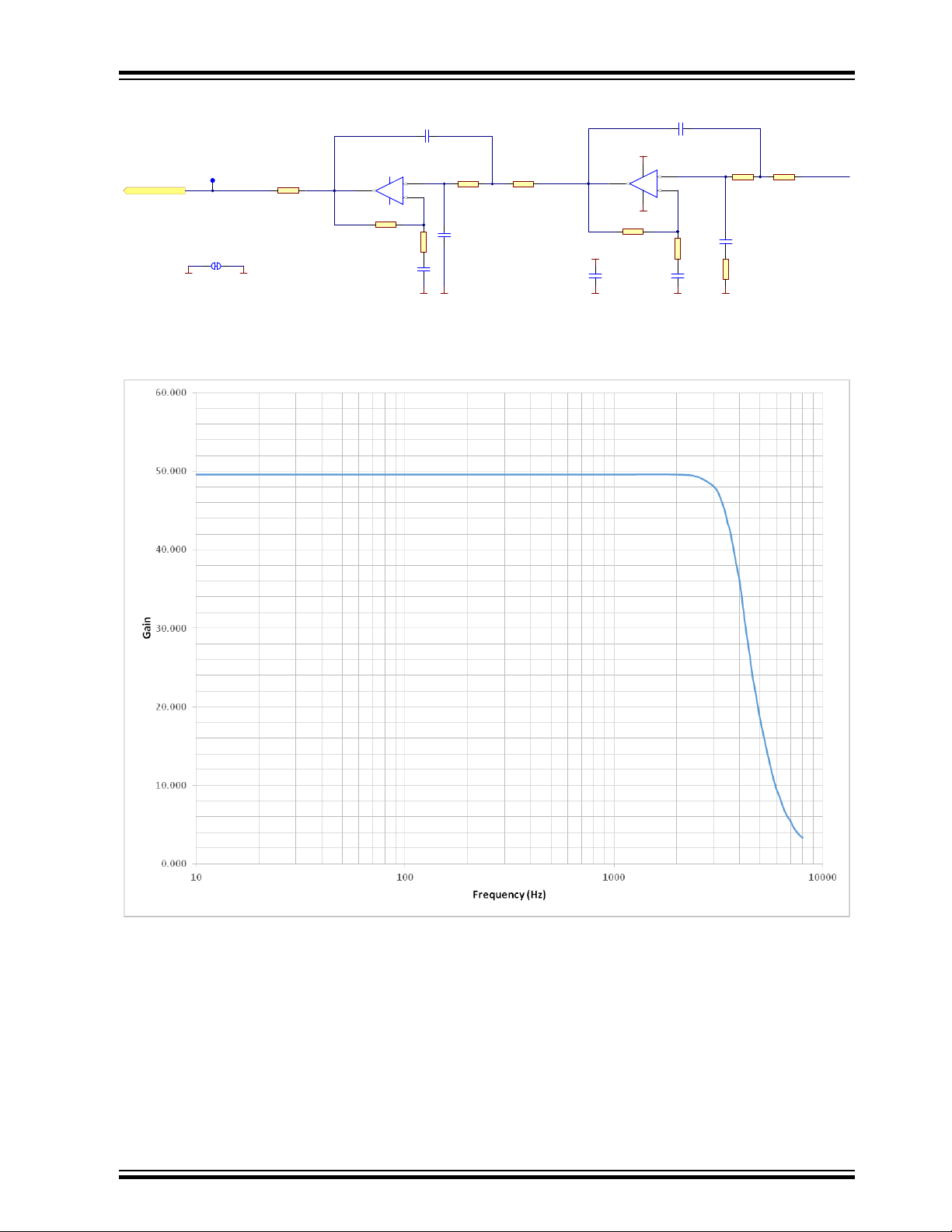
As shown in the figure below, the original signal is processed in a 4-order Sallen-Key Butterworth lowpass filter. The filter is designed to have a gain of 50 and a cut-off frequency of 4kHz. The amplified signal
is connected to the MCU ADC input 11 (pin PB0_AIN11).
© 2017 Microchip Technology Inc.
User Guide
DS40001916A-page 4
Page 5
Mic. with P re-Amp lification an d filter
TP6
-
+
5
6
7
U5B
MCP6002-I/SN
10nF
C39
5.6k
R39
1.5nF
C24
100nF
C22
GND
VCC_P3V3
15k
R42
PB0_AIN11
-
+
3
2
1
84
U5A
MCP6002-I/SN
SGND
VCC_P3V3
15k
R24
2.4k
R25
SGND
GND
1uF
C23
0R
R44
10nF
C21
2.2nF
C16
11k
R23
6.8k
R22
SGNDSGND
2.4k
R43
1uF
C40
SGND GND
J6
18k
R40
0R
R41
Parrot Hardware
Figure 2-2. Amplifier and Filter Circuit
The real filter response vs. frequency curve based on measured data is shown in the figure below.
Figure 2-3. Gain vs. Frequency Curve for the Low-pass Filter of the MIC
2.3 Microcontroller
The ATtiny817 is a tinyAVR 8-bit microcontroller with up to 8KB Flash, 512 bytes of SRAM, and 128 bytes
of EEPROM in a 14-, 20-, and 24-pin package.
The microcontroller uses the latest technologies from Microchip Technology Inc. with a flexible and lowpower architecture including Event System and SleepWalking, accurate analog features, and advanced
peripherals.
© 2017 Microchip Technology Inc.
User Guide
DS40001916A-page 5
Page 6
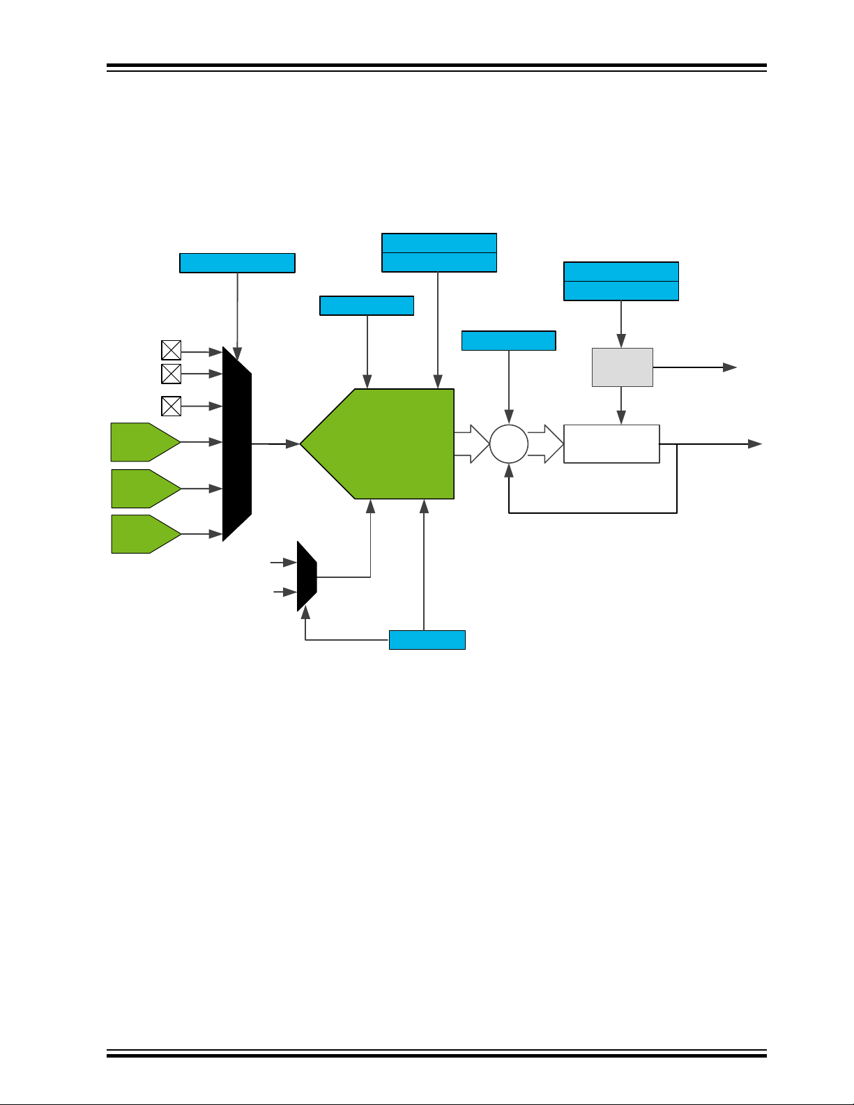
2.3.1 ADC
The Analog-to-Digital Convert (ADC) peripheral features a 10-bit successive approximation ADC with
capability of a sampling rate of up to 150ksps. The ADC is connected to a 12-channel Analog Multiplexer,
which allows twelve single-ended voltage inputs. The single-ended voltage inputs refer to 0V (GND).
For more detail, refer to the latest data sheet of ATtiny817 available at http://www.microchip.com/
wwwproducts/en/attiny817.
Figure 2-4. ATtiny817 ADC Block Diagram
MUXPOS
CTRLA
EVCTRL
COMMAND
Start
Conversion
Parrot Hardware
WINLT
WINHT
AIN0
AIN1
AIN11
DAC
VREF
TEMP
2.3.2 DAC
The Digital-to-Analog Converter (DAC) converts a digital value to a voltage. ATtiny817 features an 8-bit
Resistor String type DAC, capable of converting 350,000 samples per second (350ksps), with the internal
Voltage Reference (VREF) as upper limit for conversion. The DAC has one continuous time output with
high drive capabilities, which is able to drive a 5kΩ or 50pF load. The DAC has one analog output pin
(DACOUT), namely the PA06, that must be configured before it can be used.
...
Internal ref
VDD
ADC
VREF
Reference sel.
Enable,
Resolution
CTRLC
prescaler
CTRLB
Number of
Accumulated
Samples
+
<
>
RES
accumulate
Threshold
(IRQ)
Result Ready
(IRQ)
© 2017 Microchip Technology Inc.
User Guide
DS40001916A-page 6
Page 7

Figure 2-5. ATtiny817 DAC Block Diagram
DAC
DATA
Output
Driver
CTRLA
8
ENABLE
OUTEN
VREF
peripherals
other
OUT
TP4
-
+
3
2
1
84
U3A
MCP6002-I/SN
-
+
5
6
7
U3B
MCP6002-I/SN
-
+
3
2
1
84
U2A
MCP6002-I/SN
-
+
5
6
7
U2B
MCP6002-I/SN
PA6_DACOUT
1uF
C5
150kR5100k
R6
150k
R1
470pF
C8
SGND
220pF
C1
GND
VCC_P3V3
330kR7180k
R8
330k
R2
270pF
C9
SGND
100pF
C2
330kR9300k
R10
330k
R3
330pF
C10
SGND
47p
C3
330k
R11
270k
R12
330k
R4
1nF
C11
SGND
18pF
C4
GND
VCC_P3V3
C6
1uF
OP AMP Filter
100nF
C12
GND
VCC_P3V3
100nF
C13
GND
VCC_P3V3
SGND
39k
R16
24k
R17
VCC_P3V3
100nF
C14
DAC_VF_HALF
2.4 Filter for DAC
This filter is an 8-order Butterworth low-pass filter with 1V/V gain. The cut-off frequency is designed to be
4kHz with 0.5dB allowable pass band ripple.
Figure 2-6. 8-order Low-pass Chebyshev Filter
Parrot Hardware
As shown in the figure below, the curve is based on measured data of the filter on the board.
© 2017 Microchip Technology Inc.
User Guide
DS40001916A-page 7
Page 8

Figure 2-7. Gain vs. Frequency Curve for the 8-order Low-pass Filter
MCP6002-I/SN
C6
1uF
TP3
GND
10R
R14
47nF
C7
110k
R13
VCC_VBUS_P5V0
TP1
TP2
BTL AM P for Spea ker
SGND
8 ohm, 2W
Speaker 2831
1
2
SP1
3
2
8
1
4
5
6
7
U1
LM386M-1
3
2
8
1
4
5
6
7
U4
LM386M-1
GND
VCC_VBUS_P5V0
WH0141-1(14*1) B10K
1 3
2
VR1
POT_METER_3P S2B-PH-K-S
1
2
J1
HEADER-2
100k
R15
SGND
C38
4.7uF
VCC_VBUS_P5V0
GND
SGND
Parrot Hardware
2.5 Power Amplifier
Figure 2-8. Power Amplifier for the Speaker
As shown in the figure above, the LM386M-1 amplifier device is powered by USB +5V. The gain from the
power amplifier circuit is fixed to 20 V/V. The input of this circuit is the analog output of the 8-order low
power filter for the DAC.
In front of the power amplifier, one variable resistor (VR1) and a couple of relative resistors construct a
simple circuit for the users to adjust the loudspeaker volume.
© 2017 Microchip Technology Inc.
User Guide
DS40001916A-page 8
Page 9

2.6 User Interfaces
13
4 2
SKRAAKE010
SW1
GND
100k
R28
User Bu tton
PC5_USER_BTN
100nF
C30
VCC_P3V3
TP8
1 3
42
SKRAAKE010
SW2
100nF
C33
GND
REC .
R34
1k
1 3
42
SKRAAKE010
SW3
100nF
C34
GND
PLAY/ST OP
R35
1k
1 3
42
SKRAAKE010
SW4
100nF
C35
GND
BACK
R36
1k
1 3
42
SKRAAKE010
SW5
100nF
C36
GND
FOR WARD
R37
1k
TP17 TP18 TP19 TP20
PB5
PB6
PB7
PA7
1 3
42
SKRAAKE010
SW6
100nF
C37
GND
ERASE
R38
1k
TP21
PB4
This button is
reserved for user.
2.6.1 Buttons
There are six functional buttons on the board:
• “REC” button, to start or stop the microphone recording
• “PLAY/STOP” button, to playback the recorded sound
• “BACK” button, to jump to previous sound data
• “FORWARD” button, to jump to forward sound data
• “ERASE” button, to erase sound data
• “USER” button, reserved for users
Figure 2-9. Buttons
Parrot Hardware
Table 2-2. Pin Map for the Buttons
Button Name I/O Pin
PLAY/STOP PB5
FORWARD PB7
2.6.2 LEDs
There are two LEDs on the board, as shown in the figure below. The firmware determines the use of the
LEDs.
Figure 2-10. Status LEDs
REC PB4
BACK PB6
ERASE PA7
USER PC5
© 2017 Microchip Technology Inc.
User Guide
DS40001916A-page 9
Page 10

Table 2-3. Pin Map for the LEDs
Recommended LEDs name ATtiny817 I/O pin Color
Power LED PB3 Green
Record LED PB2 Red
2.7 External Data Flash
This data Flash from Microchip is an 8Mb SPI serial Flash. It supports single voltage read and write
operations under 2.7-3.6V power supply.
Figure 2-11. External Data Flash
Parrot Hardware
Table 2-4. Pinout for the SPI Interface
SPI Signal Name MCU SPI Pin Data Flash Pin
SCK PA3 pin #6
SS PA4 pin #1
MISO PA2 pin #2
MOSI PA1 pin #5
2.8 UPDI Programming Interface
The ATtiny817 supports UPDI (Unified Program and Debug Interface), which is a Microchip proprietary
interface for external programming and on-chip debugging of a device.
Atmel-ICE supports the UPDI interface. The 2x3 connector for the interface is a 2.54mm pitch throughhole header.
© 2017 Microchip Technology Inc.
User Guide
DS40001916A-page 10
Page 11

Figure 2-12. UPDI Interface
GND
1 2
3 4
5 6
GND
VCC
MOSI
MISO
SCK
RESET
J11
UPDI Header
PA0_UPDI_DATA
VCC_P3V3
TP7
UPDI header
connect to
Atmel-ICE.
Table 2-5. Pin Map for ATtiny817 UPDI Interface
Signal Name Pin Number in the Header Pin Number in the MCU
PA0_UPDI_DATA 1 23
VCC 2 4
GND 6 3
Parrot Hardware
© 2017 Microchip Technology Inc.
User Guide
DS40001916A-page 11
Page 12

3. Firmware Programming
3.1 Connection
The UPDI Interface is dedicated for the code debugging or reprogramming for the ATtiny817 device.
Atmel-ICE supports this operation.
Figure 3-1. Connection for the Reprogramming
Parrot Hardware
3.2 Firmware
The latest firmware is available through Atmel START: http://start.atmel.com/
Search AVR42777 Parrotʼ in the Examples browser. The project user guide instructions outline how to
download the .atzip package and import the project into Atmel Studio 7.0.
3.3 Programming
Atmel Studio can be used to program the device. Go to Tools → Device Programming → Memories.
© 2017 Microchip Technology Inc.
User Guide
DS40001916A-page 12
Page 13

Figure 3-2. Programming Interface in Atmel Studio
Parrot Hardware
© 2017 Microchip Technology Inc.
User Guide
DS40001916A-page 13
Page 14

4. Revision History
Doc. Rev. Date Comments
A 07/2017 Initial document release.
Parrot Hardware
© 2017 Microchip Technology Inc.
User Guide
DS40001916A-page 14
Page 15

5. Object of Declaration
EU Declaration of Conformity for Parrot Field Engagement Board
This declaration of conformity is issued by the manufacturer.
The development/evaluation tool is designed to be used for research and development in a laboratory
environment. This development/evaluation tool is not a Finished Appliance, nor is it intended for
incorporation into Finished Appliances that are made commercially available as single functional units to
end users under EU EMC Directive 2004/108/EC and as supported by the European Commission's Guide
for the EMC Directive 2004/108/EC (8th February 2010).
This development/evaluation tool complies with EU RoHS2 Directive 2011/65/EU.
This development/evaluation tool, when incorporating wireless and radio-telecom functionality, is in
compliance with the essential requirement and other relevant provisions of the R&TTE Directive
1999/5/EC and the FCC rules as stated in the declaration of conformity provided in the module datasheet
and the module product page available at www.microchip.com.
For information regarding the exclusive, limited warranties applicable to Microchip products, please see
Microchip’s standard terms and conditions of sale, which are printed on our sales documentation and
available at www.microchip.com.
Parrot Hardware
Signed for and on behalf of Microchip Technology Inc. at Chandler, Arizona, USA.
© 2017 Microchip Technology Inc.
User Guide
DS40001916A-page 15
Page 16

Parrot Hardware
The Microchip Web Site
Microchip provides online support via our web site at http://www.microchip.com/. This web site is used as
a means to make files and information easily available to customers. Accessible by using your favorite
Internet browser, the web site contains the following information:
• Product Support – Data sheets and errata, application notes and sample programs, design
resources, user’s guides and hardware support documents, latest software releases and archived
software
• General Technical Support – Frequently Asked Questions (FAQ), technical support requests,
online discussion groups, Microchip consultant program member listing
• Business of Microchip – Product selector and ordering guides, latest Microchip press releases,
listing of seminars and events, listings of Microchip sales offices, distributors and factory
representatives
Customer Change Notification Service
Microchip’s customer notification service helps keep customers current on Microchip products.
Subscribers will receive e-mail notification whenever there are changes, updates, revisions or errata
related to a specified product family or development tool of interest.
To register, access the Microchip web site at http://www.microchip.com/. Under “Support”, click on
“Customer Change Notification” and follow the registration instructions.
Customer Support
Users of Microchip products can receive assistance through several channels:
• Distributor or Representative
• Local Sales Office
• Field Application Engineer (FAE)
• Technical Support
Customers should contact their distributor, representative or Field Application Engineer (FAE) for support.
Local sales offices are also available to help customers. A listing of sales offices and locations is included
in the back of this document.
Technical support is available through the web site at: http://www.microchip.com/support
Microchip Devices Code Protection Feature
Note the following details of the code protection feature on Microchip devices:
• Microchip products meet the specification contained in their particular Microchip Data Sheet.
• Microchip believes that its family of products is one of the most secure families of its kind on the
market today, when used in the intended manner and under normal conditions.
• There are dishonest and possibly illegal methods used to breach the code protection feature. All of
these methods, to our knowledge, require using the Microchip products in a manner outside the
operating specifications contained in Microchip’s Data Sheets. Most likely, the person doing so is
engaged in theft of intellectual property.
• Microchip is willing to work with the customer who is concerned about the integrity of their code.
© 2017 Microchip Technology Inc.
User Guide
DS40001916A-page 16
Page 17

Parrot Hardware
• Neither Microchip nor any other semiconductor manufacturer can guarantee the security of their
code. Code protection does not mean that we are guaranteeing the product as “unbreakable.”
Code protection is constantly evolving. We at Microchip are committed to continuously improving the
code protection features of our products. Attempts to break Microchip’s code protection feature may be a
violation of the Digital Millennium Copyright Act. If such acts allow unauthorized access to your software
or other copyrighted work, you may have a right to sue for relief under that Act.
Legal Notice
Information contained in this publication regarding device applications and the like is provided only for
your convenience and may be superseded by updates. It is your responsibility to ensure that your
application meets with your specifications. MICROCHIP MAKES NO REPRESENTATIONS OR
WARRANTIES OF ANY KIND WHETHER EXPRESS OR IMPLIED, WRITTEN OR ORAL, STATUTORY
OR OTHERWISE, RELATED TO THE INFORMATION, INCLUDING BUT NOT LIMITED TO ITS
CONDITION, QUALITY, PERFORMANCE, MERCHANTABILITY OR FITNESS FOR PURPOSE.
Microchip disclaims all liability arising from this information and its use. Use of Microchip devices in life
support and/or safety applications is entirely at the buyer’s risk, and the buyer agrees to defend,
indemnify and hold harmless Microchip from any and all damages, claims, suits, or expenses resulting
from such use. No licenses are conveyed, implicitly or otherwise, under any Microchip intellectual
property rights unless otherwise stated.
Trademarks
The Microchip name and logo, the Microchip logo, AnyRate, AVR, AVR logo, AVR Freaks, BeaconThings,
BitCloud, CryptoMemory, CryptoRF, dsPIC, FlashFlex, flexPWR, Heldo, JukeBlox, KeeLoq, KeeLoq logo,
Kleer, LANCheck, LINK MD, maXStylus, maXTouch, MediaLB, megaAVR, MOST, MOST logo, MPLAB,
OptoLyzer, PIC, picoPower, PICSTART, PIC32 logo, Prochip Designer, QTouch, RightTouch, SAM-BA,
SpyNIC, SST, SST Logo, SuperFlash, tinyAVR, UNI/O, and XMEGA are registered trademarks of
Microchip Technology Incorporated in the U.S.A. and other countries.
ClockWorks, The Embedded Control Solutions Company, EtherSynch, Hyper Speed Control, HyperLight
Load, IntelliMOS, mTouch, Precision Edge, and Quiet-Wire are registered trademarks of Microchip
Technology Incorporated in the U.S.A.
Adjacent Key Suppression, AKS, Analog-for-the-Digital Age, Any Capacitor, AnyIn, AnyOut, BodyCom,
chipKIT, chipKIT logo, CodeGuard, CryptoAuthentication, CryptoCompanion, CryptoController,
dsPICDEM, dsPICDEM.net, Dynamic Average Matching, DAM, ECAN, EtherGREEN, In-Circuit Serial
Programming, ICSP, Inter-Chip Connectivity, JitterBlocker, KleerNet, KleerNet logo, Mindi, MiWi,
motorBench, MPASM, MPF, MPLAB Certified logo, MPLIB, MPLINK, MultiTRAK, NetDetach, Omniscient
Code Generation, PICDEM, PICDEM.net, PICkit, PICtail, PureSilicon, QMatrix, RightTouch logo, REAL
ICE, Ripple Blocker, SAM-ICE, Serial Quad I/O, SMART-I.S., SQI, SuperSwitcher, SuperSwitcher II, Total
Endurance, TSHARC, USBCheck, VariSense, ViewSpan, WiperLock, Wireless DNA, and ZENA are
trademarks of Microchip Technology Incorporated in the U.S.A. and other countries.
SQTP is a service mark of Microchip Technology Incorporated in the U.S.A.
Silicon Storage Technology is a registered trademark of Microchip Technology Inc. in other countries.
GestIC is a registered trademark of Microchip Technology Germany II GmbH & Co. KG, a subsidiary of
Microchip Technology Inc., in other countries.
All other trademarks mentioned herein are property of their respective companies.
©
2017, Microchip Technology Incorporated, Printed in the U.S.A., All Rights Reserved.
© 2017 Microchip Technology Inc.
User Guide
DS40001916A-page 17
Page 18

Parrot Hardware
ISBN: 978-1-5224-1937-2
Quality Management System Certified by DNV
ISO/TS 16949
Microchip received ISO/TS-16949:2009 certification for its worldwide headquarters, design and wafer
fabrication facilities in Chandler and Tempe, Arizona; Gresham, Oregon and design centers in California
and India. The Company’s quality system processes and procedures are for its PIC® MCUs and dsPIC
DSCs, KEELOQ® code hopping devices, Serial EEPROMs, microperipherals, nonvolatile memory and
analog products. In addition, Microchip’s quality system for the design and manufacture of development
systems is ISO 9001:2000 certified.
®
© 2017 Microchip Technology Inc.
User Guide
DS40001916A-page 18
Page 19

Worldwide Sales and Service
AMERICAS ASIA/PACIFIC ASIA/PACIFIC EUROPE
Corporate Office
2355 West Chandler Blvd.
Chandler, AZ 85224-6199
Tel: 480-792-7200
Fax: 480-792-7277
Technical Support:
http://www.microchip.com/
support
Web Address:
www.microchip.com
Atlanta
Duluth, GA
Tel: 678-957-9614
Fax: 678-957-1455
Austin, TX
Tel: 512-257-3370
Boston
Westborough, MA
Tel: 774-760-0087
Fax: 774-760-0088
Chicago
Itasca, IL
Tel: 630-285-0071
Fax: 630-285-0075
Dallas
Addison, TX
Tel: 972-818-7423
Fax: 972-818-2924
Detroit
Novi, MI
Tel: 248-848-4000
Houston, TX
Tel: 281-894-5983
Indianapolis
Noblesville, IN
Tel: 317-773-8323
Fax: 317-773-5453
Tel: 317-536-2380
Los Angeles
Mission Viejo, CA
Tel: 949-462-9523
Fax: 949-462-9608
Tel: 951-273-7800
Raleigh, NC
Tel: 919-844-7510
New York, NY
Tel: 631-435-6000
San Jose, CA
Tel: 408-735-9110
Tel: 408-436-4270
Canada - Toronto
Tel: 905-695-1980
Fax: 905-695-2078
Asia Pacific Office
Suites 3707-14, 37th Floor
Tower 6, The Gateway
Harbour City, Kowloon
Hong Kong
Tel: 852-2943-5100
Fax: 852-2401-3431
Australia - Sydney
Tel: 61-2-9868-6733
Fax: 61-2-9868-6755
China - Beijing
Tel: 86-10-8569-7000
Fax: 86-10-8528-2104
China - Chengdu
Tel: 86-28-8665-5511
Fax: 86-28-8665-7889
China - Chongqing
Tel: 86-23-8980-9588
Fax: 86-23-8980-9500
China - Dongguan
Tel: 86-769-8702-9880
China - Guangzhou
Tel: 86-20-8755-8029
China - Hangzhou
Tel: 86-571-8792-8115
Fax: 86-571-8792-8116
China - Hong Kong SAR
Tel: 852-2943-5100
Fax: 852-2401-3431
China - Nanjing
Tel: 86-25-8473-2460
Fax: 86-25-8473-2470
China - Qingdao
Tel: 86-532-8502-7355
Fax: 86-532-8502-7205
China - Shanghai
Tel: 86-21-3326-8000
Fax: 86-21-3326-8021
China - Shenyang
Tel: 86-24-2334-2829
Fax: 86-24-2334-2393
China - Shenzhen
Tel: 86-755-8864-2200
Fax: 86-755-8203-1760
China - Wuhan
Tel: 86-27-5980-5300
Fax: 86-27-5980-5118
China - Xian
Tel: 86-29-8833-7252
Fax: 86-29-8833-7256
China - Xiamen
Tel: 86-592-2388138
Fax: 86-592-2388130
China - Zhuhai
Tel: 86-756-3210040
Fax: 86-756-3210049
India - Bangalore
Tel: 91-80-3090-4444
Fax: 91-80-3090-4123
India - New Delhi
Tel: 91-11-4160-8631
Fax: 91-11-4160-8632
India - Pune
Tel: 91-20-3019-1500
Japan - Osaka
Tel: 81-6-6152-7160
Fax: 81-6-6152-9310
Japan - Tokyo
Tel: 81-3-6880- 3770
Fax: 81-3-6880-3771
Korea - Daegu
Tel: 82-53-744-4301
Fax: 82-53-744-4302
Korea - Seoul
Tel: 82-2-554-7200
Fax: 82-2-558-5932 or
82-2-558-5934
Malaysia - Kuala Lumpur
Tel: 60-3-6201-9857
Fax: 60-3-6201-9859
Malaysia - Penang
Tel: 60-4-227-8870
Fax: 60-4-227-4068
Philippines - Manila
Tel: 63-2-634-9065
Fax: 63-2-634-9069
Singapore
Tel: 65-6334-8870
Fax: 65-6334-8850
Taiwan - Hsin Chu
Tel: 886-3-5778-366
Fax: 886-3-5770-955
Taiwan - Kaohsiung
Tel: 886-7-213-7830
Taiwan - Taipei
Tel: 886-2-2508-8600
Fax: 886-2-2508-0102
Thailand - Bangkok
Tel: 66-2-694-1351
Fax: 66-2-694-1350
Austria - Wels
Tel: 43-7242-2244-39
Fax: 43-7242-2244-393
Denmark - Copenhagen
Tel: 45-4450-2828
Fax: 45-4485-2829
Finland - Espoo
Tel: 358-9-4520-820
France - Paris
Tel: 33-1-69-53-63-20
Fax: 33-1-69-30-90-79
France - Saint Cloud
Tel: 33-1-30-60-70-00
Germany - Garching
Tel: 49-8931-9700
Germany - Haan
Tel: 49-2129-3766400
Germany - Heilbronn
Tel: 49-7131-67-3636
Germany - Karlsruhe
Tel: 49-721-625370
Germany - Munich
Tel: 49-89-627-144-0
Fax: 49-89-627-144-44
Germany - Rosenheim
Tel: 49-8031-354-560
Israel - Ra’anana
Tel: 972-9-744-7705
Italy - Milan
Tel: 39-0331-742611
Fax: 39-0331-466781
Italy - Padova
Tel: 39-049-7625286
Netherlands - Drunen
Tel: 31-416-690399
Fax: 31-416-690340
Norway - Trondheim
Tel: 47-7289-7561
Poland - Warsaw
Tel: 48-22-3325737
Romania - Bucharest
Tel: 40-21-407-87-50
Spain - Madrid
Tel: 34-91-708-08-90
Fax: 34-91-708-08-91
Sweden - Gothenberg
Tel: 46-31-704-60-40
Sweden - Stockholm
Tel: 46-8-5090-4654
UK - Wokingham
Tel: 44-118-921-5800
Fax: 44-118-921-5820
© 2017 Microchip Technology Inc.
User Guide
DS40001916A-page 19
 Loading...