

Page 1

OS8121X Slim Board Family
User’s Guide
2017 Microchip Technology Inc. DS60001523A
Page 2

YSTEM
CERTIFIE DBYDNV
== ISO/TS16949==
Note the following details of the code protection feature on Microchip devices:
• Microchip products meet the specification contained in their particular Microchip Data Sheet.
• Microchip believes that its family of products is one of the most secure families of its kind on the market today, when used in the
intended manner and under normal conditions.
• There are dishonest and possibly illegal methods used to breach the code protection feature. All of these methods, to our
knowledge, require using the Microchip products in a manner outside the operating specifications contained in Microchip’s Data
Sheets. Most likely, the person doing so is engaged in theft of intellectual property.
• Microchip is willing to work with the customer who is concerned about the integrity of their code.
• Neither Microchip nor any other semiconductor manufacturer can guarantee the security of their code. Code protection does not
mean that we are guaranteeing the product as “unbreakable.”
Code protection is constantly evolving. We at Microchip are committed to continuously improving the code protection features of our
products. Attempts to break Microchip’s code protection feature may be a violation of the Digital Millennium Copyright Act. If such acts
allow unauthorized access to your software or other copyrighted work, you may have a right to sue for relief under that Act.
Information contained in this publication regarding device
applications and the like is provided only for your convenience
and may be superseded by updates. It is your responsibility to
ensure that your application meets with your specifications.
MICROCHIP MAKES NO REPRESENTATIONS OR
WARRANTIES OF ANY KIND WHETHER EXPRESS OR
IMPLIED, WRITTEN OR ORAL, STATUTORY OR
OTHERWISE, RELATED TO THE INFORMATION,
INCLUDING BUT NOT LIMITED TO ITS CONDITION,
QUALITY, PERFORMANCE, MERCHANTABILITY OR
FITNESS FOR PURPOSE. Microchip disclaims all liability
arising from this information and its use. Use of Microchip
devices in life support and/or safety applications is entirely at
the buyer’s risk, and the buyer agrees to defend, indemnify and
hold harmless Microchip from any and all damages, claims,
suits, or expenses resulting from such use. No licenses are
conveyed, implicitly or otherwise, under any Microchip
intellectual property rights unless otherwise stated.
Microchip received ISO/TS-16949:2009 certification for its worldwide
headquarters, design and wafer fabrication facilities in Chandler and
Tempe, Arizona; Gresham, Oregon and design centers in California
and India. The Company’s quality system processes and procedures
are for its PIC
devices, Serial EEPROMs, microperipherals, nonvolatile memory and
analog products. In addition, Microchip’s quality system for the design
and manufacture of development systems is ISO 9001:2000 certified.
®
MCUs and dsPIC® DSCs, KEELOQ
®
code hopping
QUALITYMANAGEMENTS
Trademarks
The Microchip name and logo, the Microchip logo, AnyRate, AVR,
AVR logo, AVR Freaks, BeaconThings, BitCloud, CryptoMemory,
CryptoRF, dsPIC, FlashFlex, flexPWR, Heldo, JukeBlox, KEELOQ,
KEELOQ logo, Kleer, LANCheck, LINK MD, maXStylus,
maXTouch, MediaLB, megaAVR, MOST, MOST logo, MPLAB,
OptoLyzer, PIC, picoPower, PICSTART, PIC32 logo, Prochip
Designer, QTouch, RightTouch, SAM-BA, SpyNIC, SST, SST
Logo, SuperFlash, tinyAVR, UNI/O, and XMEGA are registered
trademarks of Microchip Technology Incorporated in the U.S.A.
and other countries.
ClockWorks, The Embedded Control Solutions Company,
EtherSynch, Hyper Speed Control, HyperLight Load, IntelliMOS,
mTouch, Precision Edge, and Quiet-Wire are registered
trademarks of Microchip Technology Incorporated in the U.S.A.
Adjacent Key Suppression, AKS, Analog-for-the-Digital Age, Any
Capacitor, AnyIn, AnyOut, BodyCom, chipKIT, chipKIT logo,
CodeGuard, CryptoAuthentication, CryptoCompanion,
CryptoController, dsPICDEM, dsPICDEM.net, Dynamic Average
Matching, DAM, ECAN, EtherGREEN, In-Circuit Serial
Programming, ICSP, Inter-Chip Connectivity, JitterBlocker,
KleerNet, KleerNet logo, Mindi, MiWi, motorBench, MPASM, MPF,
MPLAB Certified logo, MPLIB, MPLINK, MultiTRAK, NetDetach,
Omniscient Code Generation, PICDEM, PICDEM.net, PICkit,
PICtail, PureSilicon, QMatrix, RightTouch logo, REAL ICE, Ripple
Blocker, SAM-ICE, Serial Quad I/O, SMART-I.S., SQI,
SuperSwitcher, SuperSwitcher II, Total Endurance, TSHARC,
USBCheck, VariSense, ViewSpan, WiperLock, Wireless DNA, and
ZENA are trademarks of Microchip Technology Incorporated in the
U.S.A. and other countries.
SQTP is a service mark of Microchip Technology Incorporated in
the U.S.A.
Silicon Storage Technology is a registered trademark of Microchip
Technology Inc. in other countries.
GestIC is a registered trademark of Microchip Technology
Germany II GmbH & Co. KG, a subsidiary of Microchip Technology
Inc., in other countries.
All other trademarks mentioned herein are property of their
respective companies.
© 2017, Microchip Technology Incorporated, All Rights Reserved.
ISBN: 978-1-5224-2176-4
DS60001523A-page 2 2017 Microchip Technology Inc.
Page 3

EU Declaration of Conformity
This declaration of conformity is issued by the manufacturer.
The development/evaluation tool is designed to be used for research and development in a laboratory environment. This
development/evaluation tool is not intended to be a finished appliance, nor is it intended for incorporation into finished appliances that are
made commercially available as single functional units to end users. This development/evaluation tool complies with EU EMC Directive
2004/108/EC and as supported by the European Commission's Guide for the EMC Directive 2004/108/EC (8th February 2010).
This development/evaluation tool complies with EU RoHS2 Directive 2011/65/EU.
This development/evaluation tool, when incorporating wireless and radio-telecom functionality, is in compliance with the essential
requirement and other relevant provisions of the R&TTE Directive 1999/5/EC and the FCC rules as stated in the declaration of conformity
provided in the module datasheet and the module product page available at www.microchip.com.
For information regarding the exclusive, limited warranties applicable to Microchip products, please see Microchip’s standard terms and
conditions of sale, which are printed on our sales documentation and available at www.microchip.com.
Signed for and on behalf of Microchip Technology Inc. at Chandler, Arizona, USA.
Objects of Declaration: OS81210 USB Application Boards, OS81214 Slim Microphone Board,
OS81214 Slim Auxiliary I/O Board, Power Injector Box
2017 Microchip Technology Inc. DS60001523A-page 3
Page 4

OS8121X Slim Board Family
NOTES:
DS60001523A-page 4 2017 Microchip Technology Inc.
Page 5

OS8121X SLIM BOARD FAMILY
USER’S GUIDE
Table of Contents
Preface ........................................................................................................................... 7
Introduction............................................................................................................ 7
Intended Use ......................................................................................................... 7
Scope of Delivery .................................................................................................. 8
Document Layout .................................................................................................. 8
Term Definitions .................................................................................................... 9
Recommended Reading........................................................................................ 9
Customer Support ................................................................................................. 9
Document Revision History ................................................................................. 10
Chapter 1. Introduction ............................................................................................... 11
Chapter 2. OS81210 USB Application Boards
2.1 Overview ...................................................................................................... 13
2.2 Product Features .......................................................................................... 14
2.3 Functional Description .................................................................................. 14
2.4 Board Details ................................................................................................ 15
2.4.1 Electrical Characteristics ........................................................................... 15
2.4.2 Connectors ................................................................................................ 15
2.4.3 LEDs .......................................................................................................... 16
2.5 Assembly Plan and Mechanical Dimensions ................................................ 17
2.5.1 Top View and Mechanical Dimensions ...................................................... 17
2.5.2 Bottom View .............................................................................................. 18
Chapter 3. OS81214 Slim Microphone Board
3.1 Overview ...................................................................................................... 19
3.2 Product Features .......................................................................................... 20
3.3 Functional Description .................................................................................. 20
3.4 Board Details ................................................................................................ 21
3.4.1 Electrical Characteristics ........................................................................... 21
3.4.2 Connectors ................................................................................................ 21
3.4.3 LED ........................................................................................................... 21
3.5 Assembly Plan and Mechanical Dimensions ................................................ 22
3.5.1 Top View and Mechanical Dimensions ...................................................... 22
3.5.2 Bottom View .............................................................................................. 23
Chapter 4. OS81214 Slim Auxiliary I/O Board
4.1 Overview ...................................................................................................... 25
4.2 Product Features .......................................................................................... 26
4.3 Functional Description .................................................................................. 26
2017 Microchip Technology Inc. DS60001523A-page 5
Page 6

OS8121X Slim Board Family
4.4 Board Details ................................................................................................ 27
4.4.1 Electrical Characteristics ............................................................................27
4.4.2 Microphone Power .....................................................................................27
4.4.3 Connectors .................................................................................................27
4.4.4 LEDs ..........................................................................................................28
4.5 Assembly Plan and Mechanical Dimensions ................................................ 29
4.5.1 Top View and Mechanical Dimensions ......................................................29
4.5.2 Bottom View ...............................................................................................30
Chapter 5. Power Injector Box
5.1 Overview ...................................................................................................... 31
5.2 Electrical Characteristics .............................................................................. 31
5.3 On/Off Switch ............................................................................................... 31
5.4 Connectors ................................................................................................... 32
5.4.1 Electrical Connector (ePHY) ......................................................................32
5.4.2 Power Connector .......................................................................................32
5.5 Power LED ................................................................................................... 32
5.6 Technical Specifications ............................................................................... 33
Worldwide Sales and Service .....................................................................................34
DS60001523A-page 6 2017 Microchip Technology Inc.
Page 7
OS8121X SLIM BOARD FAMILY
USER’S GUIDE
Preface
NOTICE TO CUSTOMERS
All documentation becomes dated, and this manual is no exception. Microchip tools and
documentation are constantly evolving to meet customer needs, so some actual dialogs
and/or tool descriptions may differ from those in this document. Please refer to our web site
(www.microchip.com) to obtain the latest documentation available.
Documents are identified with a “DS” number. This number is located on the bottom of each
page, in front of the page number. The numbering convention for the DS number is
“DSXXXXXA”, where “XXXXX” is the document number and “A” is the revision level of the
document.
INTRODUCTION
INTENDED USE
This chapter contains general information that will be useful to know before using a
Slim Board. Topics discussed in this chapter include:
• Intended Use
• Scope of Delivery
• Document Layout
• Term Definitions
• Recommended Reading
• Customer Support
• Document Revision History
This Microchip product is intended to be used for developing or testing MOST® network
based multimedia products and systems by persons with experience in developing
multimedia devices.
Note: The operation of this Microchip product is only admitted with original
Microchip devices.
Do not interfere with the product's original state. Otherwise user safety,
faultless operation and electromagnetic compatibility are not ensured.
To avoid electric shocks and short circuits use this device only in an appropriate environment.
This open device may exceed the limits of electromagnetic interference.
Electromagnetic compatibility can be only achieved if the equipment is built
into an appropriate housing.
2017 Microchip Technology Inc. DS60001523A-page 7
Page 8
OS8121X Slim Board Family
SCOPE OF DELIVERY
The delivery includes the following parts:
• One Slim Board
• One ePHY cable
The Slim Board can be identified by the label affixed on the bottom side of the board.
For the OS81210 USB Application Boards the label starts with either a prefixed capital
M or S, identifying the board as an USB master (M) or USB slave (S) board, see example below.
The first five numbers represent the part number of each Slim Board.
Check your shipment for completeness.
If you have any complaints, direct them to your local Microchip sales and service office,
listed on the last page of this document. Providing the delivery note number eases the
handling.
DOCUMENT LAYOUT
This user’s guide describes how to use a Slim Board and the Power Injector Box. The
document is organized as follows:
• Chapter 1, Introduction – This chapter introduces the OS8121X Slim Board Family
and shows a case of application.
• Chapter 2, OS81210 USB Application Boards; Chapter 3, OS81214 Slim Micro-
phone Board and Chapter 4, OS81214 Slim Auxiliary I/O Board – For each Slim
Board these chapters start with a description of a typical use case. They show an
image of the board, list product features and provide a functional description. Furthermore, they explain board details, show the assembly plans and mechanical
dimensions.
• Chapter 5, Power Injector Box – This chapter describes the Power Injector Box.
DS60001523A-page 8 2017 Microchip Technology Inc.
Page 9

TERM DEFINITIONS
This user’s guide uses the following term definitions:
ALSA Advanced Linux
ePHY Electrical Physical Layer
GND Ground
I²C Inter-Integrated Circuit
I²S™ Inter-IC Sound
INIC Intelligent Network Interface Controller
LED Light Emitting Diode
MCU Micro Controller Unit
MEMS Micro-Electro-Mechanical Systems
NC Not Connected
PoDL Power over Data Line
RMS Root Mean Square
SoC System on Chip
USB Universal Serial Bus
Term Description
®
Sound Architecture
Preface
RECOMMENDED READING
This user’s guide describes how to use a Slim Board. Other useful documents are listed
below. To obtain documents, contact: support-ais-de@microchip.com.
[1] INIC Hardware Data Sheet
[2] INIC Interface Specification
[3] Microchip Automotive Target Manager User’s Guide
[4] INIC Device Update Process User’s Guide
CUSTOMER SUPPORT
Users of Microchip products can receive assistance through several channels:
• Distributor or Representative
• Local Sales Office
• Field Application Engineer (FAE)
• Technical Support
Customers should contact their distributor, representative or field application engineer
(FAE) for support. Local sales offices are also available to help customers. A listing of
sales offices and locations is included in the back of this document.
Technical support is available through support-ais-de@microchip.com.
2017 Microchip Technology Inc. DS60001523A-page 9
Page 10

OS8121X Slim Board Family
DOCUMENT REVISION HISTORY
Revision A (October 2017)
• Initial release of this document.
DS60001523A-page 10 2017 Microchip Technology Inc.
Page 11
OS8121X SLIM BOARD FAMILY
USER’S GUIDE
Chapter 1. Introduction
The OS8121X Slim Board Family is a powerful set of different demonstration boards
that have been designed to showcase a variety of application-specific use cases, such
as the operation of several audio instances.
Available demonstration boards are the:
• OS81210 USB Application Boards (available as USB master or USB slave board)
• OS81214 Slim Auxiliary I/O Board
• OS81214 Slim Microphone Board
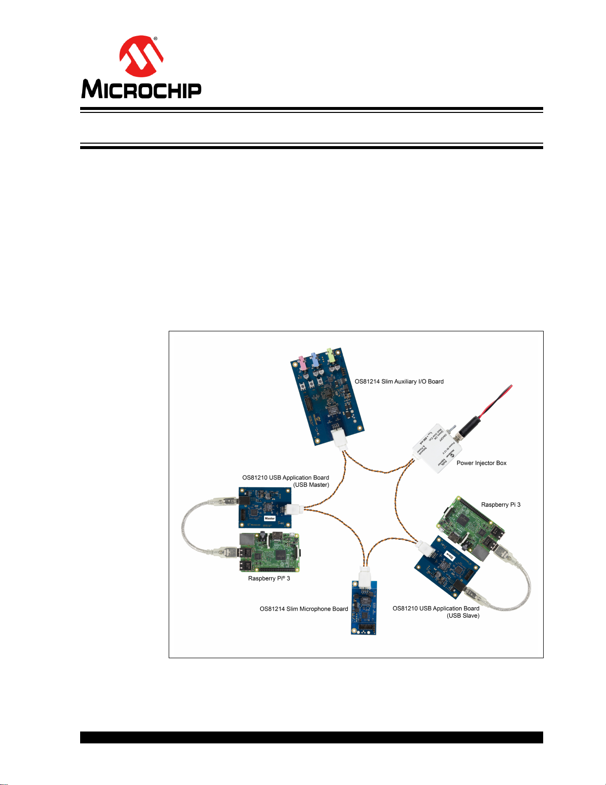
Figure 1-1 shows a powerful and low-cost example setup that uses Slim Boards; both
Raspberry Pi
Slim Boards.
FIGURE 1-1: EXAMPLE SETUP
®
3 are running Linux. The Power Injector Box is required for powering the
2017 Microchip Technology Inc. DS60001523A-page 11
Page 12

OS8121X Slim Board Family
The idea behind the Slim design pattern is to avoid an MCU running on all but one of
the devices in the network. However, a controlling instance is needed to allow a wide
variety of use cases. This instance is an OS81210 USB Application Board, which connects via USB to an MCU or SoC.
For Kernel driver and application examples for Linux contact:
support-ais-de@microchip.com.
DS60001523A-page 12 2017 Microchip Technology Inc.
Page 13

Chapter 2. OS81210 USB Application Boards
2.1 OVERVIEW
An OS81210 USB Application Board is available in two flavors: as USB master board
and USB slave board. A USB slave board has per default the configuration interface
disabled, which allows the configuration of INIC resources, such as ports and sockets
from network side. The USB master board has per default the configuration interface
enabled, which allows a locally attached EHC the configuration of INIC resources (configuration requests from network side are rejected). Both boards are identifiable by a
Master or Slave sticker affixed on the top side of the board.
OS81210 USB Application Boards are used to interface a controlling instance to the
network. In many cases this will be a single board computer or a laptop running Linux.
The boards are used to configure any Slim Board on the network and to feed and
receive audio streams to/from the network. If the MOST Linux Driver is used, a record
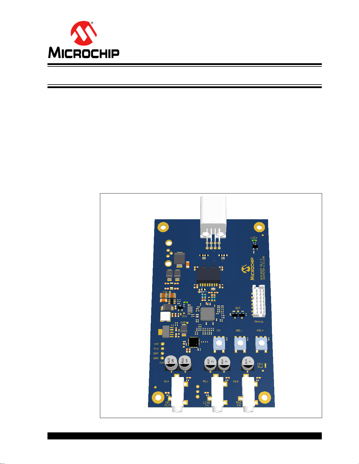
or playback ALSA interface can be utilized for this purpose. An image of the board is
shown in Figure 2-1.
FIGURE 2-1: OS81210 USB APPLICATION BOARD
OS8121X SLIM BOARD FAMILY
USER’S GUIDE
2017 Microchip Technology Inc. DS60001523A-page 13
Page 14
OS8121X Slim Board Family
INIC
Configuration/
Debug Header
Connector
1.8 V
3.3 V
Power Supply
Network
and
PoDL
12 V
USB
5 V
Physical
Layer
Interface
USB
Connector
Reset
2.2 PRODUCT FEATURES
• Detached interface between application hardware and network
• Supports a network speed grade of 50 Mbits/s
• Available for electrical physical layer (ePHY) applications
• Configuration/Debug Header Connector
• Offers connection capabilities to the USB port
• Lock detection monitor (Lock LED)
• The USB master board is identified in the network by its node address 0x0200
• The USB slave board is identified in the network by its node address 0x02B0
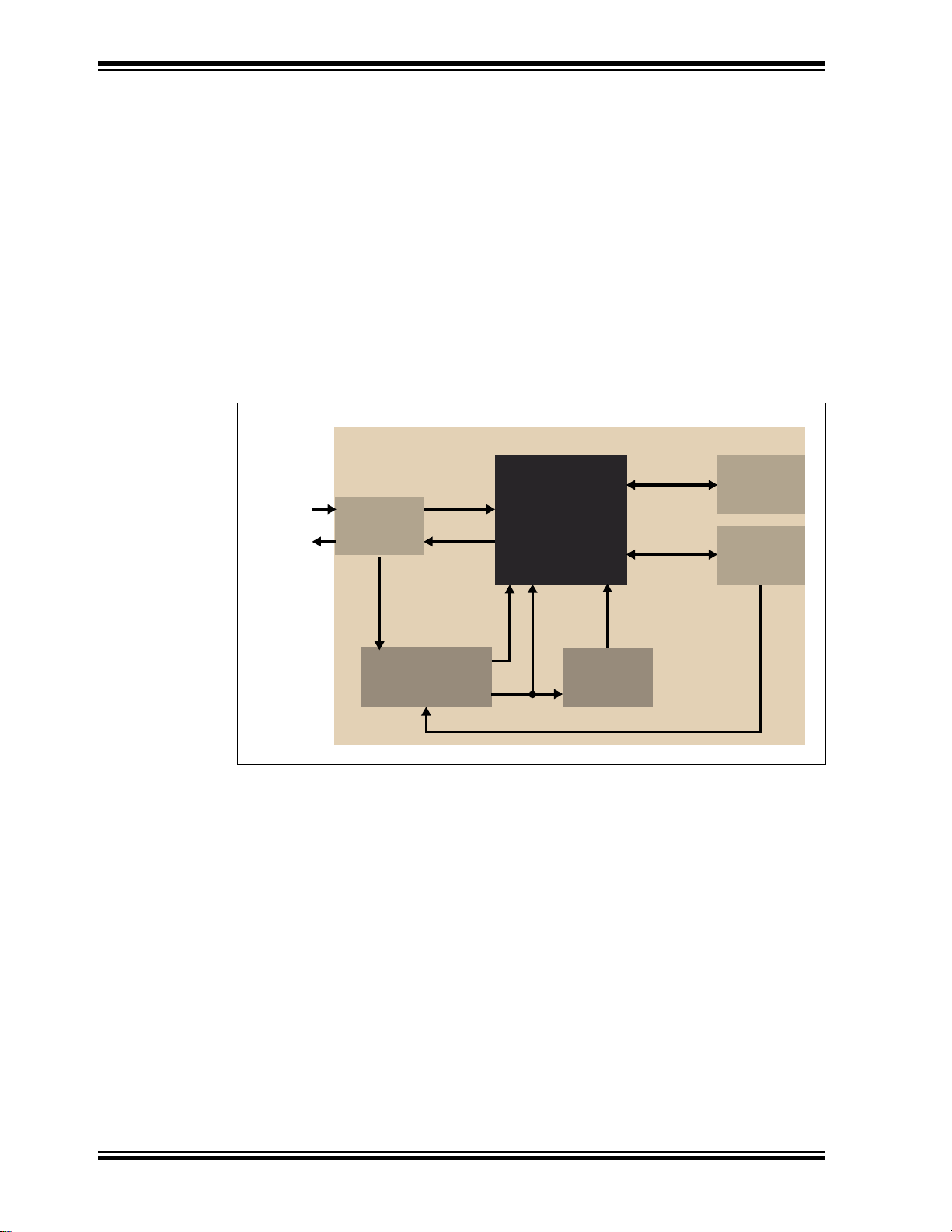
2.3 FUNCTIONAL DESCRIPTION
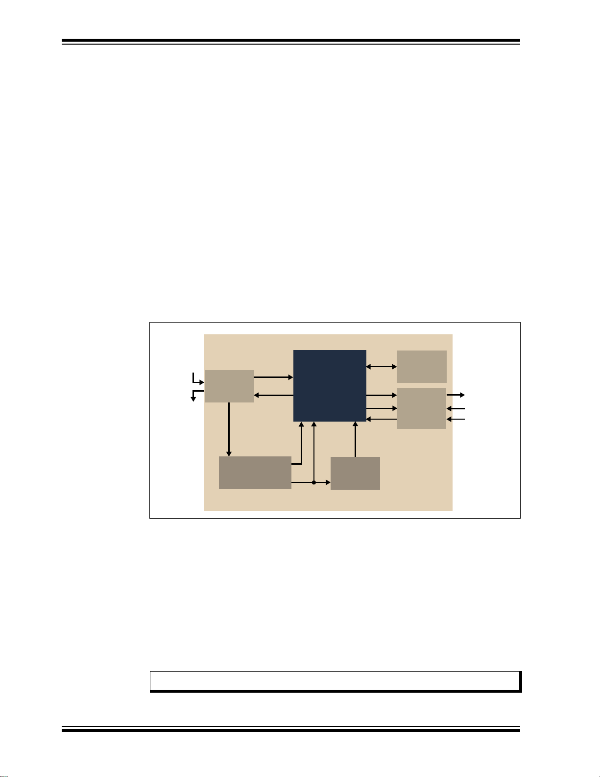
Figure 2-2 gives an overview of the board’s main components.
FIGURE 2-2: BLOCK DIAGRAM
An OS81210 USB Application Board provides an electrical Physical Layer (ePHY)
interface to the network. The electrical interface is implemented with passive front-end
components [1]. If the board is connected with the Power Injector Box, the 12 V of the
box are used to feed the on-board power supply, which provides 1.8 V INIC core supply
and 3.3 V for INIC I/Os and other components. As long as the output voltage of the
power supply is not stable, the INIC will be hold in reset.
The Configuration/Debug Header Connector is used to read, load or customize the
INIC’s initial start-up configuration data.
DS60001523A-page 14 2017 Microchip Technology Inc.
The USB connector is used to connect the board to USB applications. For more information refer to the INIC Hardware Data Sheet [1]. If the Power Injector Box is not connected, the board can also be powered via the USB connector.
Page 15

2.4 BOARD DETAILS
2.4.1 Electrical Characteristics
Board Current Consumption at — 90 — mA
Board Operating Voltage 9 12 15 V
USB Connector Current at — 190 — mA
USB Connector Voltage 4.75 5 5.25 V
2.4.2 Connectors
All connectors are mounted on the top side of the board.
2.4.2.1 CONFIGURATION/DEBUG HEADER CONNECTOR
The Configuration/Debug Header [1] connector is used as an interface between the
INIC and an INIC debug/configuration tool. In combination with the Microchip Automotive Target Manager [3], initial configuration data [2] can be loaded into the INIC.
For more information contact: support-ais-de@microchip.com.
For the update process refer to the INIC Device Update Process User’s Guide [4].
OS81210 USB Application Boards
Parameter Min. Typ. Max. Unit
Type: 87832-1420, from Molex
®
Suitable counter-piece: 87568-1493, from Molex
The connector pins are described in Table 2-1.
TABLE 2-1: CONFIGURATION/DEBUG HEADER – PIN DESCRIPTION
Pin Description
1, 3, 13 NC
2, 5, 10 GND
4 Error/Boot
6, 9 3.3 V
7TDI/DSDA
8TCK/DSCL
11 TDO/DINT
12 Reset
14 TMS
2.4.2.2 ELECTRICAL CONNECTOR (ePHY)
The electrical interface connector is used as the interface to the network.
Type: 1376350-2, from Tyco
Suitable counter-piece: 1376352-1, from Tyco
2017 Microchip Technology Inc. DS60001523A-page 15
Page 16
OS8121X Slim Board Family
2.4.2.3 USB CONNECTOR
An OS81210 USB Application Board provides a USB connector to connect to a USB
device.
Type: 614 004 161 21, standard type B, female, from Würth
Suitable counter-piece: CAUBLKAB-2M, USB Cable Type A male/Type B male,
from L-COM
®
2.4.3 LEDs
All LEDs are mounted on the top side of the Slim Board.
The table below gives an overview of the LEDs and the states they signal.
Name State Description
3V3 (Power) Off The Slim Board is not powered.
On (green) The Slim Board is powered.
Lock Off The INIC is not locked to the network.
On (green) The INIC is locked to the network.
®
DS60001523A-page 16 2017 Microchip Technology Inc.
Page 17

OS81210 USB Application Boards
2.5 ASSEMBLY PLAN AND MECHANICAL DIMENSIONS
2.5.1 Top View and Mechanical Dimensions
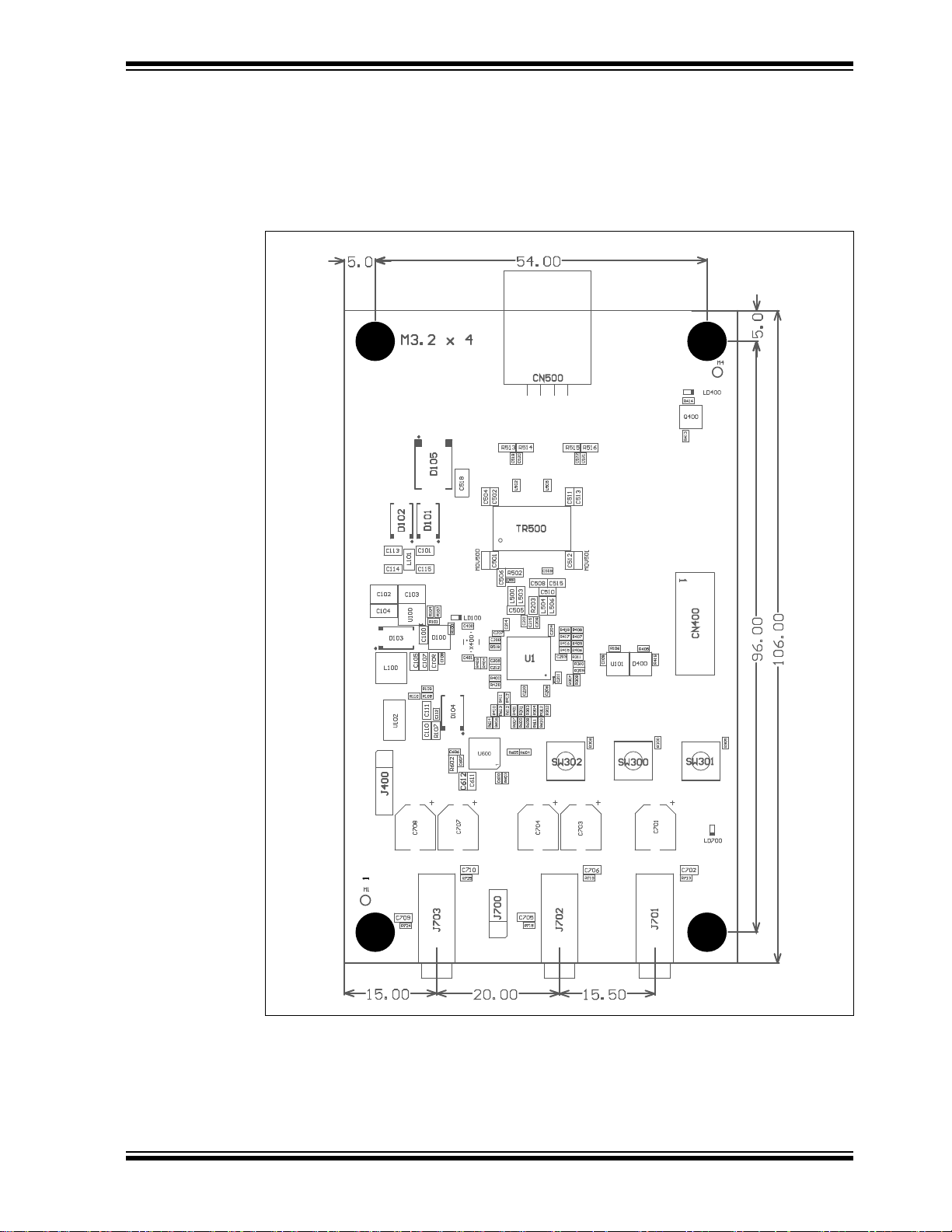
The mechanical dimensions shown in Figure 2-3 are in [mm].
FIGURE 2-3: ASSEMBLY PLAN – TOP VIEW AND MECHANICAL
DIMENSIONS
2017 Microchip Technology Inc. DS60001523A-page 17
Page 18

OS8121X Slim Board Family
2.5.2 Bottom View
FIGURE 2-4: ASSEMBLY PLAN – BOTTOM VIEW
DS60001523A-page 18 2017 Microchip Technology Inc.
Page 19

Chapter 3. OS81214 Slim Microphone Board
3.1 OVERVIEW
The OS81214 Slim Microphone Board can serve as a stereo audio source feeding the
network. The data can be routed to an OS81214 Slim Auxiliary I/O Board to make it
audible again.
For recording or further processing, the audio data can also be routed to an OS81210
USB Application Board.
An image of the board is shown in Figure 3-1.
FIGURE 3-1: OS81214 SLIM MICROPHONE BOARD
OS8121X SLIM BOARD FAMILY
USER’S GUIDE
2017 Microchip Technology Inc. DS60001523A-page 19
Page 20

OS8121X Slim Board Family
Configuration/
Debug Header
Connector
1.8 V
3.3 V
Power Supply
INIC
Network
and
PoDL
12 V
I2S
TM
Left
Physical
Layer
Interface
Reset
INMP441ACEZ-R7
INMP441ACEZ-R7
Right
3.2 PRODUCT FEATURES
• Supports a network speed grade of 50 Mbits/s
• Available for electrical physical layer (ePHY) applications
• Configuration/Debug Header Connector
• One streaming port
• Lock detection monitor (Lock LED)
• Is identified in the network by its node address 0x0210
3.3 FUNCTIONAL DESCRIPTION
Figure 3-2 gives an overview of the board’s main components.
FIGURE 3-2: BLOCK DIAGRAM
The OS81214 Slim Microphone Board provides an electrical Physical Layer (ePHY)
interface to the network. The electrical interface is implemented with passive front-end
components [1]. The Power Injector Box provides 12 V that are used to feed the onboard power supply, which provides 1.8 V INIC core supply and 3.3 V for INIC I/Os and
other components. As long as the output voltage of the power supply is not stable, the
INIC will be hold in reset.
The Configuration/Debug Header Connector is used to read, load or customize the
INIC’s initial start-up configuration data.
The two on-board omni-directional MEMS microphones are connected to the INIC via
2
one I
S port. Together, they provide a stereo microphone input.
DS60001523A-page 20 2017 Microchip Technology Inc.
Page 21

3.4 BOARD DETAILS
3.4.1 Electrical Characteristics
Board Current Consumption at — 60 — mA
Board Operating Voltage 9 12 15 V
3.4.2 Connectors
The OS81214 Slim Microphone Board provides the following connectors:
• One ePHY connector
• One Configuration/Debug Header connector
For information on the connectors refer to Section 2.4.2.
3.4.3 LED
The OS81214 Slim Microphone Board provides a Lock LED, which is mounted on the
top side of the Slim Board.
The table below shows the states the LED can signal.
OS81214 Slim Microphone Board
Parameter Min. Typ. Max. Unit
Name State Description
Lock Off The INIC is not locked to the network.
On (green) The INIC is locked to the network.
2017 Microchip Technology Inc. DS60001523A-page 21
Page 22

OS8121X Slim Board Family
3.5 ASSEMBLY PLAN AND MECHANICAL DIMENSIONS
3.5.1 Top View and Mechanical Dimensions
The mechanical dimensions shown in Figure 3-3 are in [mm].
FIGURE 3-3: ASSEMBLY PLAN – TOP VIEW AND MECHANICAL
DIMENSIONS
DS60001523A-page 22 2017 Microchip Technology Inc.
Page 23

OS81214 Slim Microphone Board
3.5.2 Bottom View
FIGURE 3-4: ASSEMBLY PLAN – BOTTOM VIEW
2017 Microchip Technology Inc. DS60001523A-page 23
Page 24

OS8121X Slim Board Family
NOTES:
DS60001523A-page 24 2017 Microchip Technology Inc.
Page 25
Chapter 4. OS81214 Slim Auxiliary I/O Board
4.1 OVERVIEW
The OS81214 Slim Auxiliary I/O Board is used to sink and source stereo audio streams
from and to the network. It is able to deliver a stereo audio label sourced by an
OS81210 USB Application Board, OS81214 Slim Microphone Board or another
OS81214 Slim Auxiliary I/O Board to its headphone jack to make it audible on a connected headphone or speaker.
In parallel an audio stream from the microphone or Line In can be sourced to the network and routed to an OS81214 Slim Auxiliary I/O Board to make it audible again. For
recording or further processing, the audio data can also be routed to an OS81210 USB
Application Board.
An image of the board is shown in Figure 4-1.
FIGURE 4-1: OS81214 SLIM AUXILIARY I/O BOARD
OS8121X SLIM BOARD FAMILY
USER’S GUIDE
2017 Microchip Technology Inc. DS60001523A-page 25
Page 26
OS8121X Slim Board Family
Configuration/
Debug Header
Connector
1.8 V
3.3 V
Power Supply
INIC
Network
and
PoDL
12 V
I2C
I
2
S_B
I
2STM
_A
Headphone
Line In
Microphone
Physical
Layer
Interface
Reset
UDA 1380
4.2 PRODUCT FEATURES
• Supports a network speed grade of 50 Mbits/s
• Available for electrical physical layer (ePHY) applications
• Configuration/Debug Header Connector
• Lock detection monitor (Lock LED)
• Active jack (for noise cancellation; audio sockets are only active when jack is
plugged-in)
• Microphone input (with phantom power)
• Line input
• Headphone output
• One button for channel select
• Two buttons for volume adjust
• Is identified in the network by its node address 0x0240
4.3 FUNCTIONAL DESCRIPTION
Figure 4-2 gives an overview of the board’s main components.
FIGURE 4-2: BLOCK DIAGRAM
The OS81214 Slim Auxiliary I/O Board provides an electrical Physical Layer (ePHY)
interface to the network. The electrical interface is implemented with passive front-end
components [1]. The Power Injector Box provides 12 V that are used to feed the onboard power supply, which provides 1.8 V INIC core supply and 3.3 V for INIC I/Os and
other components. As long as the output voltage of the power supply is not stable, the
INIC will be hold in reset.
The Configuration/Debug Header Connector is used to read, load or customize the
INIC’s initial start-up configuration data.
DS60001523A-page 26 2017 Microchip Technology Inc.
The stereo audio codec UDA1380 is connected to the INIC through one I
two Streaming (I
mono microphone input.
Note: Use of microphone and line input at the same time is not supported.
2
S) ports. It provides a headphone output, a stereo line input and a
2
C port and
Page 27

4.4 BOARD DETAILS
12 3
4.4.1 Electrical Characteristics
Board Current Consumption at — 70 — mA
Board Operating Voltage 9 12 15 V
Headphone Output Power (R
Line In Voltage — — 1 V (RMS)
Microphone Input Voltage — — 35 mV (RMS)
Microphone DC Bias — 3.3
Note 1: Through 2.2 kΩ resistor. For details refer to Section 4.4.2.
4.4.2 Microphone Power
The OS81214 Slim Auxiliary I/O Board supports standard electret microphones that
need a bias voltage. Figure 4-3 shows the pin assignment on the 3.5 mm stereo plug.
FIGURE 4-3: PIN ASSIGNMENT OF STEREO PLUG
OS81214 Slim Auxiliary I/O Board
Parameter Min. Typ. Max. Unit
= 16 Ω)30 35 40 mW (RMS)
L
1
—V
1: Signal input
2: 3.3 V through 2.2 kΩ resistor
3: GND
4.4.3 Connectors
The OS81214 Slim Auxiliary I/O Board provides the following connectors:
• One ePHY connector
• One Configuration/Debug Header connector
• Three audio sockets
For information on the electrical and Configuration/Debug Header connectors refer to
Section 2.4.2. The audio socket connectors are described in Section 4.4.3.1.
4.4.3.1 AUDIO SOCKET
The OS81214 Slim Auxiliary I/O Board provides the following audio socket connectors:
Headphone socket type: SJ-3524-SMT-TR-GR, standard jack, stereo, 3.5 mm,
green, from CUI Inc.
Line In socket type: SJ-3524-SMT-TR-BE, standard jack, stereo, 3.5 mm,
blue, from CUI Inc.
Microphone socket type: SJ-3524-SMT-TR-PI, standard jack, stereo, 3.5 mm,
pink, from CUI Inc.
Suitable counter-piece: SP-3501, stereo plug, 3.5 mm male, from CUI Inc.
2017 Microchip Technology Inc. DS60001523A-page 27
Page 28

OS8121X Slim Board Family
4.4.4 LEDs
All LEDs are mounted on the top side of the Slim Board.
The table below gives an overview of the LEDs and the states they signal.
Name State Description
Power — See Section 2.4.3
Lock
Microphone Power Off Microphone is not powered.
On (yellow) Microphone is powered (with phantom power).
DS60001523A-page 28 2017 Microchip Technology Inc.
Page 29
OS81214 Slim Auxiliary I/O Board
4.5 ASSEMBLY PLAN AND MECHANICAL DIMENSIONS
4.5.1 Top View and Mechanical Dimensions
The mechanical dimensions shown in Figure 4-4 are in [mm].
FIGURE 4-4: ASSEMBLY PLAN – TOP VIEW AND MECHANICAL
DIMENSIONS
2017 Microchip Technology Inc. DS60001523A-page 29
Page 30

OS8121X Slim Board Family
4.5.2 Bottom View
FIGURE 4-5: ASSEMBLY PLAN – BOTTOM VIEW
DS60001523A-page 30 2017 Microchip Technology Inc.
Page 31
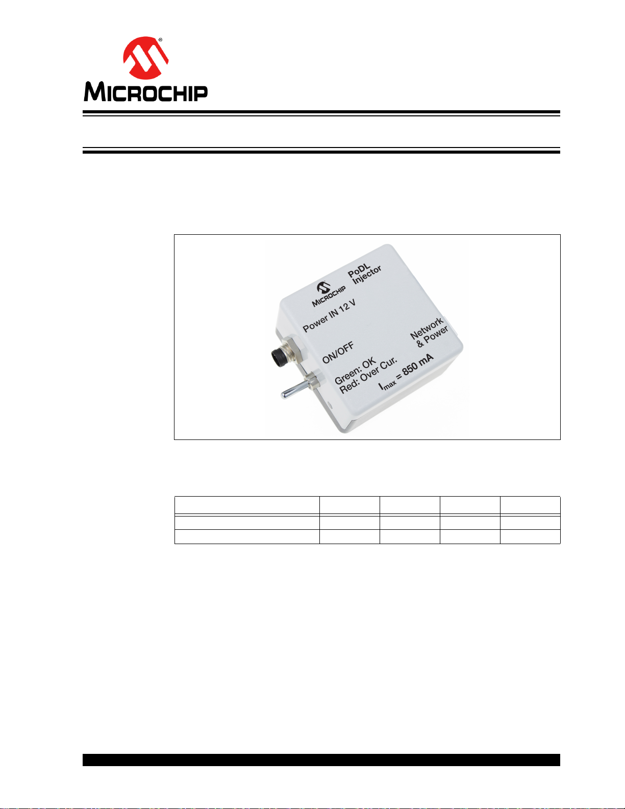
5.1 OVERVIEW
The Power Injector Box is used to power the Slim Boards.
A photo of the box is shown in Figure 5-1.
FIGURE 5-1: POWER INJECTOR BOX
OS8121X SLIM BOARD FAMILY
USER’S GUIDE
Chapter 5. Power Injector Box
5.2 ELECTRICAL CHARACTERISTICS
Parameter Min. Typ. Max. Unit
Power In Voltage 9 12 15 V
Output Current — — 850 mA
5.3 ON/OFF SWITCH
The ON/OFF switch is used to switch on/off the Power Injector Box.
2017 Microchip Technology Inc. DS60001523A-page 31
Page 32

OS8121X Slim Board Family
1
2
3
5.4 CONNECTORS
5.4.1 Electrical Connector (ePHY)
The electrical connector cable of the Power Injector Box provides the power for the
boards and is connected to the Slim Boards as shown in Figure 1-1.
Type: 1376350-2 from Tyco
Suitable counter-piece: 1376352-1 from Tyco
5.4.2 Power Connector
The power connector must be connected to a 12 V DC power supply.
The connector pins are illustrated in Figure 5-2.
FIGURE 5-2: POWER CONNECTOR
The pin assignment is as described in Tab l e 5 -1 .
TABLE 5-1: POWER CONNECTOR - PIN DESCRIPTION
Type: 09-3419-82-03, sensor connector series 718, 3 pole,
Suitable counter-piece: 99 3400 100 03, M8, IP67, series 768, 3 pole,
5.5 POWER LED
The power LED indicates different power states:
Power Off Device is not powered.
Note 1: If an over current condition has been detected, the output power of the Power Injec-
Pin Number Signal Description
1 12 V DC Power supply
2NC —
3 GND Ground
from Binder
from Binder
Name State Description
On (green) Device is powered.
On (red) Over current condition has been detected, or the
input power is out of the permitted range.
tor Box will be turned off. To restart the Power Injector Box, the input power must be
switched off/on.
1
DS60001523A-page 32 2017 Microchip Technology Inc.
Page 33

5.6 TECHNICAL SPECIFICATIONS
Parameter Value Unit
Dimensions (W x D x H) 50 x 50 x 30 mm
Dimensions incl. connectors and switch (W x D x H) 75 x 50 x 30
Ambient Temperature Range 0-70 °C
Power Injector Box
2017 Microchip Technology Inc. DS60001523A-page 33
Page 34

Worldwide Sales and Service
AMERICAS
Corporate Office
2355 West Chandler Blvd.
Chandler, AZ 85224-6199
Tel: 480-792-7200
Fax: 480-792-7277
Technical Support:
http://www.microchip.com/
support
Web Address:
www.microchip.com
Atlanta
Duluth, GA
Tel: 678-957-9614
Fax: 678-957-1455
Austin, TX
Tel: 512-257-3370
Boston
Westborough, MA
Tel: 774-760-0087
Fax: 774-760-0088
Chicago
Itasca, IL
Tel: 630-285-0071
Fax: 630-285-0075
Dallas
Addison, TX
Tel: 972-818-7423
Fax: 972-818-2924
Detroit
Novi, MI
Tel: 248-848-4000
Houston, TX
Tel: 281-894-5983
Indianapolis
Noblesville, IN
Tel: 317-773-8323
Fax: 317-773-5453
Tel: 317-536-2380
Los Angeles
Mission Viejo, CA
Tel: 949-462-9523
Fax: 949-462-9608
Tel: 951-273-7800
Raleigh, NC
Tel: 919-844-7510
New York, NY
Tel: 631-435-6000
San Jose, CA
Tel: 408-735-9110
Tel: 408-436-4270
Canada - Toronto
Tel: 905-695-1980
Fax: 905-695-2078
ASIA/PACIFIC
Asia Pacific Office
Suites 3707-14, 37th Floor
Tower 6, The Gateway
Harbour City, Kowloon
Hong Kong
Tel: 852-2943-5100
Fax: 852-2401-3431
Australia - Sydney
Tel: 61-2-9868-6733
Fax: 61-2-9868-6755
China - Beijing
Tel: 86-10-8569-7000
Fax: 86-10-8528-2104
China - Chengdu
Tel: 86-28-8665-5511
Fax: 86-28-8665-7889
China - Chongqing
Tel: 86-23-8980-9588
Fax: 86-23-8980-9500
China - Dongguan
Tel: 86-769-8702-9880
China - Guangzhou
Tel: 86-20-8755-8029
China - Hangzhou
Tel: 86-571-8792-8115
Fax: 86-571-8792-8116
China - Hong Kong SAR
Tel: 852-2943-5100
Fax: 852-2401-3431
China - Nanjing
Tel: 86-25-8473-2460
Fax: 86-25-8473-2470
China - Qingdao
Tel: 86-532-8502-7355
Fax: 86-532-8502-7205
China - Shanghai
Tel: 86-21-3326-8000
Fax: 86-21-3326-8021
China - Shenyang
Tel: 86-24-2334-2829
Fax: 86-24-2334-2393
China - Shenzhen
Tel: 86-755-8864-2200
Fax: 86-755-8203-1760
China - Wuhan
Tel: 86-27-5980-5300
Fax: 86-27-5980-5118
China - Xian
Tel: 86-29-8833-7252
Fax: 86-29-8833-7256
ASIA/PACIFIC
China - Xiamen
Tel: 86-592-2388138
Fax: 86-592-2388130
China - Zhuhai
Tel: 86-756-3210040
Fax: 86-756-3210049
India - Bangalore
Tel: 91-80-3090-4444
Fax: 91-80-3090-4123
India - New Delhi
Tel: 91-11-4160-8631
Fax: 91-11-4160-8632
India - Pune
Tel: 91-20-3019-1500
Japan - Osaka
Tel: 81-6-6152-7160
Fax: 81-6-6152-9310
Japan - Tokyo
Tel: 81-3-6880- 3770
Fax: 81-3-6880-3771
Korea - Daegu
Tel: 82-53-744-4301
Fax: 82-53-744-4302
Korea - Seoul
Tel: 82-2-554-7200
Fax: 82-2-558-5932 or
82-2-558-5934
Malaysia - Kuala Lumpur
Tel: 60-3-6201-9857
Fax: 60-3-6201-9859
Malaysia - Penang
Tel: 60-4-227-8870
Fax: 60-4-227-4068
Philippines - Manila
Tel: 63-2-634-9065
Fax: 63-2-634-9069
Singapore
Tel: 65-6334-8870
Fax: 65-6334-8850
Taiwan - Hsin Chu
Tel: 886-3-5778-366
Fax: 886-3-5770-955
Taiwan - Kaohsiung
Tel: 886-7-213-7830
Taiwan - Taipei
Tel: 886-2-2508-8600
Fax: 886-2-2508-0102
Thailand - Bangkok
Tel: 66-2-694-1351
Fax: 66-2-694-1350
EUROPE
Austria - Wels
Tel: 43-7242-2244-39
Fax: 43-7242-2244-393
Denmark - Copenhagen
Tel: 45-4450-2828
Fax: 45-4485-2829
Finland - Espoo
Tel: 358-9-4520-820
France - Paris
Tel: 33-1-69-53-63-20
Fax: 33-1-69-30-90-79
Germany - Garching
Tel: 49-8931-9700
Germany - Haan
Tel: 49-2129-3766400
Germany - Heilbronn
Tel: 49-7131-67-3636
Germany - Karlsruhe
Tel: 49-721-625370
Germany - Munich
Tel: 49-89-627-144-0
Fax: 49-89-627-144-44
Germany - Rosenheim
Tel: 49-8031-354-560
Israel - Ra’anana
Tel: 972-9-744-7705
Italy - Milan
Tel: 39-0331-742611
Fax: 39-0331-466781
Italy - Padova
Tel: 39-049-7625286
Netherlands - Drunen
Tel: 31-416-690399
Fax: 31-416-690340
Norway - Trondheim
Tel: 47-7289-7561
Poland - Warsaw
Tel: 48-22-3325737
Romania - Bucharest
Tel: 40-21-407-87-50
Spain - Madrid
Tel: 34-91-708-08-90
Fax: 34-91-708-08-91
Sweden - Gothenberg
Tel: 46-31-704-60-40
Sweden - Stockholm
Tel: 46-8-5090-4654
UK - Wokingham
Tel: 44-118-921-5800
Fax: 44-118-921-5820
DS60001523A-page 34 2017 Microchip Technology Inc.
10/10/17
 Loading...