

Page 1

MRF89XAMxA PICtail™/PICtail Plus
Daughter Board User’s Guide
© 2011 Microchip Technology Inc. DS70653A
Page 2
Note the following details of the code protection feature on Microchip devices:
• Microchip products meet the specification contained in their particular Microchip Data Sheet.
• Microchip believes that its family of products is one of the most secure families of its kind on the market today, when used in the
intended manner and under normal conditions.
• There are dishonest and possibly illegal methods used to breach the code protection feature. All of these methods, to our
knowledge, require using the Microchip products in a manner outside the operating specifications contained in Microchip’s Data
Sheets. Most likely, the person doing so is engaged in theft of intellectual property.
• Microchip is willing to work with the customer who is concerned about the integrity of their code.
• Neither Microchip nor any other semiconductor manufacturer can guarantee the security of their code. Code protection does not
mean that we are guaranteeing the product as “unbreakable.”
Code protection is constantly evolving. We at Microchip are committed to continuously improving the code protection features of our
products. Attempts to break Microchip’s code protection feature may be a violation of the Digital Millennium Copyright Act. If such acts
allow unauthorized access to your software or other copyrighted work, you may have a right to sue for relief under that Act.
Information contained in this publication regarding device
applications and the like is provided only for your convenience
and may be superseded by updates. It is your responsibility to
ensure that your application meets with your specifications.
MICROCHIP MAKES NO REPRESENTATIONS OR
WARRANTIES OF ANY KIND WHETHER EXPRESS OR
IMPLIED, WRITTEN OR ORAL, STATUTORY OR
OTHERWISE, RELATED TO THE INFORMATION,
INCLUDING BUT NOT LIMITED TO ITS CONDITION,
QUALITY, PERFORMANCE, MERCHANTABILITY OR
FITNESS FOR PURPOSE. Microchip disclaims all liability
arising from this information and its use. Use of Microchip
devices in life support and/or safety applications is entirely at
the buyer’s risk, and the buyer agrees to defend, indemnify and
hold harmless Microchip from any and all damages, claims,
suits, or expenses resulting from such use. No licenses are
conveyed, implicitly or otherwise, under any Microchip
intellectual property rights.
Trademarks
The Microchip name and logo, the Microchip logo, dsPIC,
K
EELOQ, KEELOQ logo, MPLAB, PIC, PICmicro, PICSTART,
32
PIC
logo, rfPIC and UNI/O are registered trademarks of
Microchip Technology Incorporated in the U.S.A. and other
countries.
FilterLab, Hampshire, HI-TECH C, Linear Active Thermistor,
MXDEV, MXLAB, SEEVAL and The Embedded Control
Solutions Company are registered trademarks of Microchip
Technology Incorporated in the U.S.A.
Analog-for-the-Digital Age, Application Maestro, CodeGuard,
dsPICDEM, dsPICDEM.net, dsPICworks, dsSPEAK, ECAN,
ECONOMONITOR, FanSense, HI-TIDE, In-Circuit Serial
Programming, ICSP, Mindi, MiWi, MPASM, MPLAB Certified
logo, MPLIB, MPLINK, mTouch, Omniscient Code
Generation, PICC, PICC-18, PICDEM, PICDEM.net, PICkit,
PICtail, REAL ICE, rfLAB, Select Mode, Total Endurance,
TSHARC, UniWinDriver, WiperLock and ZENA are
trademarks of Microchip Technology Incorporated in the
U.S.A. and other countries.
SQTP is a service mark of Microchip Technology Incorporated
in the U.S.A.
All other trademarks mentioned herein are property of their
respective companies.
© 2011, Microchip Technology Incorporated, Printed in the
U.S.A., All Rights Reserved.
Printed on recycled paper.
ISBN: 978-1-60932-846-7
Microchip received ISO/TS-16949:2002 certification for its worldwide
headquarters, design and wafer fabrication facilities in Chandler and
T empe, Arizona; Gresham, Oregon and design centers in California
and India. The Company’s quality system processes and procedures
are for its PIC
devices, Serial EEPROMs, microperipherals, nonvolatile memo ry and
analog products. In addition, Microchip’s quality system for the desig n
and manufacture of development systems is ISO 9001:2000 certified.
®
MCUs and dsPIC® DSCs, KEELOQ
®
code hopping
DS70653A-page 2 © 2011 Microchip Technology Inc.
Page 3

MRF89XAMxA PICtail™/PICtail
PLUS DAUGHTER BOARD
USER ’S GUIDE
Table of Contents
Preface ...........................................................................................................................5
Chapter 1. Overview
1.1 Introduction ...................................................................................................11
1.2 MRF89XAMxA PICtail/PICtail Plus Daughter Board Contents ..................... 11
1.3 MRF89XAMxA PICtail/PICtail Plus Daughter Board .................................... 11
Chapter 2. Getting Started
2.1 Introduction ...................................................................................................15
2.2 Plugging into the PIC18 Explorer Board .......................................................15
2.3 Plugging into the Explorer 16 Development Board ......................................16
2.4 Downloading and Running the Demo Program ............................................ 17
Appendix A. MRF89XAMxA PICtail/PICtail Plus
Daughter Board Schematic
A.1 Introduction ..................................................................................................19
A.2 MRF89XAMxA PICtail/PICtail Plus Daughter Board Schematic .................. 20
A.3 MRF89XAMxA PICtail/PICtail Plus Daughter Board PCB Layout ...............21
A.4 MRF89XAMxA PICtail/PICtail Plus Daughter Board Bill of Materials .......... 23
Worldwide Sales and Service ....................................................................................24
© 2011 Microchip Technology Inc. DS70653A-page 3
Page 4

MRF89XAMxA PICtail™/PICtail Plus Daughter Board User’s Guide
NOTES:
DS70653A-page 4 © 2011 Microchip Technology Inc.
Page 5
MRF89XAMxA PICtail™/PICtail
PLUS DAUGHTER BOARD
USER ’S GUIDE
Preface
NOTICE TO CUSTOMERS
All documentation becomes dated, and this manual is no exception. Microchip tools and
documentation are constantly evolving to meet customer needs, so some actual dialogs
and/or tool descriptions may differ from those in this document. Please refer to our web site
(www.microchip.com) to obtain the latest documentation available.
Documents are identified with a “DS” number. This number is located on the bottom of each
page, in front of the page number. The numbering convention for the DS number is
“DSXXXXXA”, where “XXXXX” is the document number and “A” is the revision level of the
document.
For the most up-to-date information on development tools, see the MPLAB® IDE on-line help.
Select the Help menu, and then Topics to open a list of available on-line help files.
INTRODUCTION
This chapter contains general information that will be useful to know before using the
MRF89XAMxA PICtail™/PICtail Plus Daughter Board. Items discusse d in this chapter
include:
• Document Layout
• Conventions Used in this Guide
• Warranty Registration
• Recommended Reading
• The Microchip Web Site
• Development Systems Customer Change Notification Service
• Customer Support
• Document Revision History
DOCUMENT LAYOUT
This document describes how to use the MRF89XAMxA PICtail™/PICtail Plus
Daughter Board. The manual layout is as follows:
• Chapter 1. “Overview” This chapter provides an overview of the MRF89XAMxA
PICtail/PICtail Plus Daughter Board, including board contents and features.
• Chapter 2. “Getting Started” This chapter describes how to start using your
MRF89XAMxA PICtail/PICtail Plus Daughter Board.
• Appendix A. “MRF89XAMxA PICtail/PICtail Plus Daugh ter Board Schematic”
This appendix contains the schematics, PCB information and Bill of Materials for
the MRF89XAMxA PICtail/PICtail Plus Daughter Board.
© 2011 Microchip Technology Inc. DS70653A-page 5
Page 6
MRF89XAMxA PICtail™/PICtail Plus Daughter Board User’s Guide
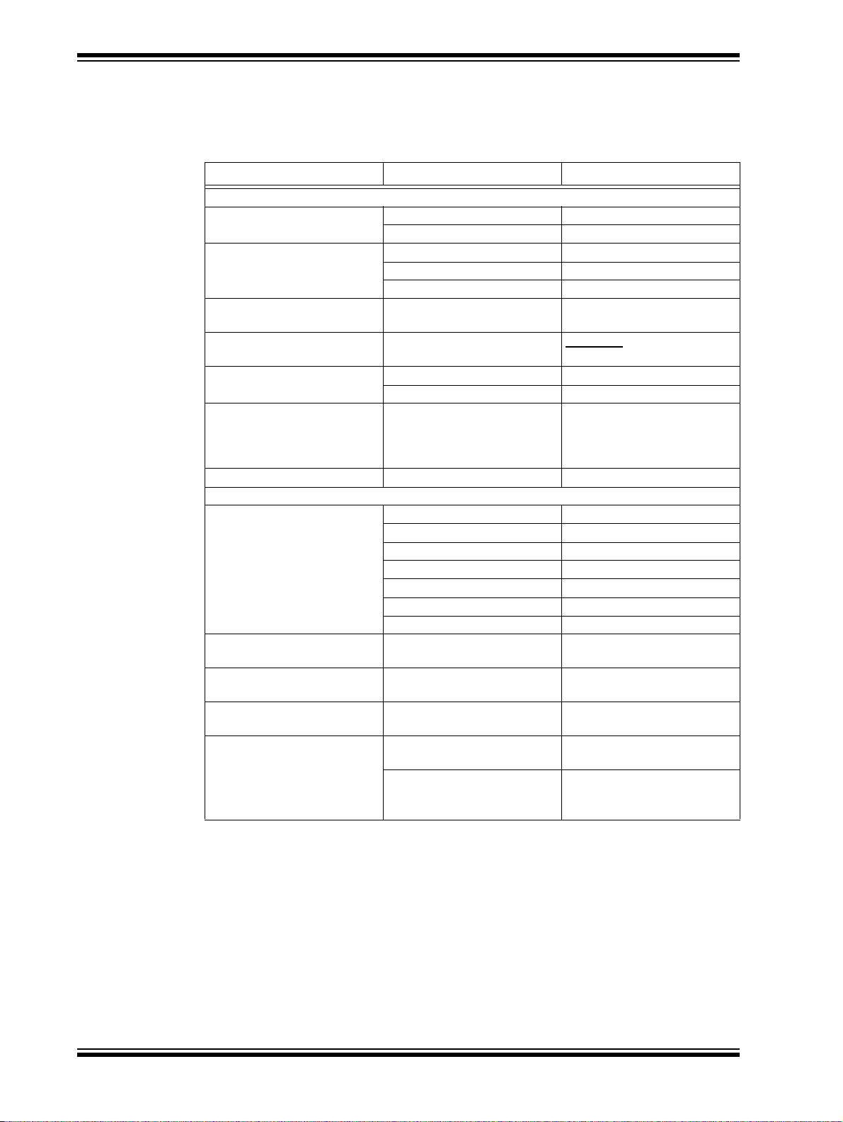
CONVENTIONS USED IN THIS GUIDE
This manual uses the following documentation conventions:
DOCUMENTATION CONVENTIONS
Description Represents Examples
Arial font:
Italic characters Referenced books MPLAB® IDE User’s Guide
Emphasized text ...is the only compiler...
Initial caps A window the Output window
A dialog the Settings dialog
A menu selection select Enable Programmer
Quotes A field name in a window or
dialog
Underlined, italic text with
right angle bracket
Bold characters A dialog button Click OK
N‘Rnnnn A number in verilog format,
Text in angle brackets < > A key on the keyboard Press <Enter>, <F1>
Courier New font:
Plain Courier New Sample source code #define START
Italic Courier New A variable argument file.o, where file can be
Square brackets [ ] Optional arguments mcc18 [options] file
Curly brackets and pipe
character: { | }
Ellipses... Replaces repeated text var_name [,
A menu path File>Save
A tab Click the Power tab
where N is the total number of
digits, R is the radix and n is a
digit.
Filenames autoexec.bat
File paths c:\mcc18\h
Keywords _asm, _endasm, static
Command-line options -Opa+, -Opa-
Bit values 0, 1
Constants 0xFF, ‘A’
Choice of mutually exclusive
arguments; an OR selection
Represents code supplied by
user
“Save project before build”
4‘b0010, 2‘hF1
any valid filename
[options]
errorlevel {0|1}
var_name...]
void main (void)
{ ...
}
DS70653A-page 6 © 2011 Microchip Technology Inc.
Page 7

WARRANTY REGISTRATION
Please complete the enclosed Warran ty Registration Card and mail it promptly.
Sending in the Warranty Registration Card entitles users to receive new product
updates. Interim software releases are available at the Microchip web site.
RECOMMENDED READING
This user's guide describes how to use the MRF89XAMxA PICtail/PICtail Plus
Daughter Board. Other useful documents are listed below. The following Microchip
documents are available and recommended as supplemental reference resources.
MRF89XA Ultra Low-Power Integrated ISM Band Sub-GHz T ransceive r (DS70622)
MRF89XAM8A 868 MHz Ultra Low- Power Sub-GHz Transceiver Module Data
Sheet (DS70651)
PICDEM™ PIC18 Explorer Demonstration Board User’s Guide (DS51721)
Explorer 16 Development Board User’s Guide (DS51589)
2K SPI Bus Serial EEPROM with EUI-48™ Node Identity Data Sheet (DS22123)
THE MICROCHIP WEB SITE
Microchip provides online support via our web site at www.microchip.com. This web
site is used as a means to make files and information easily available to customers.
Accessible by using your favorite Internet browser , the web site contains the following
information:
• Product Support – Data sheets and errata, application notes and sample
programs, design resources, user’s guides and hardware support documents,
latest software releases and archived software
• General Technical Support – Frequently Asked Questions (FAQs), technical
support requests, online discussion groups, Microchip consultant program
member listing
• Business of Microchip – Product selector and ordering guides, latest Microchip
press releases, listing of seminars and events, listings of Microchip sales offices,
distributors and factory representatives
Preface
© 2011 Microchip Technology Inc. DS70653A-page 7
Page 8

MRF89XAMxA PICtail™/PICtail Plus Daughter Board User’s Guide
DEVELOPMENT SYSTEMS CUSTOMER CHANGE NOTIFICATION SERVICE
Microchip’s customer notification service helps keep customers current on Microchip
products. Subscribers will receive e-mail notification whenever there are changes,
updates, revisions or errata related to a spec ified product family or development tool of
interest.
To register, access the Microchip web site at www.microchip.com, click on Customer
Change Notification and follow the registration instructions.
The Development Systems product group categories are:
• Compilers – The latest information on Microchip C compile rs and other language
tools. These include the MPLAB C18 and MPLAB C30 C compilers; MPASM™
and MPLAB ASM30 assemblers; MPLINK™ and MPLAB LINK30 object linkers;
and MPLIB™ and MPLAB LIB30 object librarians.
• Emulators – The latest information on Microchip in-circuit emulators.This
includes the MPLAB ICE 2000 and MPLAB ICE 4000.
• In-Circuit Debuggers – The latest information on the Microchip in-circuit
debugger , MPLAB ICD 2.
• MPLAB® IDE – The latest information on Microchip MPLAB IDE, the Windows®
Integrated Development Environment for development systems tools. This list is
focused on the MPLAB IDE, MPLAB SIM simulator, MPLAB IDE Project Manager
and general editing and debugging features.
• Programmers – The latest information on Microchip programmers. These include
the MPLAB PM3 and PRO MATE II device programmers and the PICSTART
Plus and PICkit™ 1, 2, and 3 development programmers.
®
CUSTOMER SUPPORT
Users of Microchip products can receive assistance through several channels:
• Distributor or Representative
• Local Sales Office
• Field Application Engineer (FAE)
• Technical Support
Customers should contact their distributor, representative or field application engineer
(FAE) for th e support. Local sales offices ar e also available to help customers. A listing
of sales offices and locations is included in the back of this document.
Technical support is available through the web site at: http://support.microchip.com
DOCUMENT REVISION HISTORY
Revision A (January 2011)
• This is the initial release of the document.
DS70653A-page 8 © 2011 Microchip Technology Inc.
Page 9

1.1 INTRODUCTION
The MRF89XAMxA PICtail™/PICtail Plus Daughter Board is a demonstration and
development daughter board for the following modules:
• MRF89XAM8A Ultra Low-Power Sub-GHz Transcei ver Module - 868 MHz
(AC164138-1)
• MRF89XAM9A Ultra Low-Power Sub-GHz Transcei ver Module - 915 MHz
(AC164138-2)
The daughter board can be plugged into multiple Microchip Technology demonstratio n
and development boards. For example, the daughter board is appropriate for 8-bit
microcontroller development using the PIC18 Explorer Board (DM183032) or for 16-b it
or 32-bit microcontroller development using the Explorer 16 Development Board
(DM240001).
Supporting software stacks and app lication notes can be downloaded from the
Microchip website
This chapter discusses these topics:
• MRF89XAMxA PICtail/PICtail Plus Daughter Board Contents
• MRF89XAMxA PICtail/PICtail Plus Daughter Board
MRF89XAMxA PICtail™/PICtail
PLUS DAUGHTER BOARD
USER ’S GUIDE
Chapter 1. Overview
http://www.microchip.com/wireless.
1.2 MRF89XAMxA PICtail/PICt ail PLUS DAUGHTER BOARD CONTENTS
Depending on the development tool ordered, package will contain one of the following
development boards listed in Table 1-1.
TABLE 1-1: MRF89XAMxA PICtail™/PICtail PLUS DAUGHTER BOARD
Description Part Number
MRF89XAM8A PICtail/PICtail Plus Daughter Board – 868 MHz AC164138-1
MRF89XAM9A PICtail/PICtail Plus Daughter Board – 915 MHz AC164138-2
1.3 MRF89XAMxA PICtail/PICtail PLUS DAUGHTER BOARD
The MRF89XAMxA PICtail/PICtail Plus Daughter Board is a complete Ultra Low-Power
Sub-GHz wireless transceiver. The features are shown in Figure 1-1.
CAUTION
Power to the MRF89XAMxA PICtail/PICtail Plus Daughter Board should be in the
range of 2.1–3.6V. Ensure that the development/demonstration board that the
daughter board is plugged into meets this voltage requirement; otherwise, damage
to the MRF89XA might occur.
© 2011 Microchip Technology Inc. DS70653A-page 9
Page 10

MRF89XAMxA PICtail™/PICtail Plus Daughter Board User’s Guide
MRF89XAM8A or
MRF89XAM9A Module
Power Disconnect/Current
Measure Jumpers
INT2 Jumper
PICtail™ and PICtail
Plus Connectors
25AA02E48 EUI
Node Identity
Serial EEPROM
FIGURE 1-1: MRF89XAMXA PICtail™/PICtail PLUS DAUGHTER BOARD
PICtail Plus Connector (P1) – 30-pin card edge connector for conn ecting to the16-bit
and 32-bit development boards’ PICtail Plus connector.
PICtail Connector (P2) – 28-pin right ang le connector to connect to the 8-bit develop-
ment boards’ PICtail connector.
MRF89XAM8A (U1) – Ultra Low-Power Sub-GHz transceiver module – 868 MHz.
MRF89XAM9A (U1) – Ultra Low-Power Sub-GHz transceiver module – 915 MHz.
Power Disconnect/Current Measure Jumpers (JP1/JP2) – Two 2-pin headers are
connected in parallel. A shunt on one of the two headers connects power to the
MRF89XAMxA module. A current meter can be placed on th e ope n h eader an d wh en
the shunt is removed from the opposite header , current consumption can be measured
without interrupting power. A useful cable that can be connected to the 2-pin header
and current meter, using banana plugs, is the XLP Current Measurement Cable
(AC002023).
INT2 Jumper (JP3) – Jumpering JP3 with a shunt allows you to connect RA5 to
RB2/INT2, this enables push button switch S2 to trigger an interrupt. For more
information, see
EUI Node Identity Serial EEPROM (U3) – Contains a unique IEEE EUI address. For
more information, refer to the “2K SPI Bus Serial EEPROM with EUI-48™ Node Iden
tity Data Sheet” (DS22123).
Section 2.2.1 “Configuring Push Button Switch S2 to RB2/INT2”.
-
DS70653A-page 10 © 2011 Microchip Technology Inc.
Page 11

MRF89XAMxA PICtail™/PICtail
PLUS DAUGHTER BOARD
Chapter 2. Getting Started
2.1 INTRODUCTION
The MRF89XAMxA PICtail/PICtail Plus Daughter Board can be plugged into multiple
Microchip Technology demonstration and development boards. This allows the
developer to choose the microcontroller that best suits the customer’s development
environment.
The PICtail connector right-angle header, P2, can be plugged into the PIC18 Explorer
Development Board (DM183032). The PICtail Plus card-edge connector, P1, can be
plugged into Explorer 16 Development Board (DM240001).
This chapter describes how the daughter board is plugged into the PIC18 Exp lorer and
Explorer 16 Development Boards.
2.2 PLUGGING INTO THE PIC18 EXPLORER BOARD
The MRF89XAMxA PICtail/PICtail Plus Daughter Board can be plugged into the PIC18
Explorer Board PICtail connector, J3, as shown in
to RE2 as shown.
USER ’S GUIDE
Figure 2-1. Make sure to align pin 1
CAUTION
Ensure that the PIC18F87J11 PIM is plugged into the PIC18 Explorer Board. This
sets the system V
PICtail/PICtail Plus Daughter Board.
2.2.1 Configuring Push Button Switch S2 to RB2/INT2
On the PIC18 Explorer Board, push button switch S2 is normally connected to I/O port
pin RA5. RA5 is not an interrupt-on-change or external interrupt capable I/O pin.
Jumpering JP3 with a shunt allows the connection of RA5 to RB2/INT2 to allow push
button switch S2 to trigger an interrupt. Remember that RB2 also connects to pin 10
(input) of U6 (RS232 level shifter), which is a Clear-to-Send (CTS) signal on P2 pin 8
(DE9 receptacle).
DD voltage to 3.3 volts, which is required by the MRF89XAMxA
© 2011 Microchip Technology Inc. DS70653A-page 11
Page 12

MRF89XAMxA PICtail™/PICtail Plus Daughter Board User’s Guide
FIGURE 2-1: MRF89XAMxA PICtail™/PICtail PLUS DAUGHTER BOARD
PLUGGED INTO PIC18 EXPLORER BOARD
2.3 PLUGGING INTO THE EXPLORER 16 DEVELOPMENT BOARD
The MRF89XAMxA PICtail/PICtail Plus Daughter Board can be plugged into the
Explorer 16 Development Board as shown in
The MRF89XAMxA PICtail/PICtail Plus Daughter Board’ s 3 0-pin card edg e connector
is plugged into the top section of the PICtail Plus connector. This will connect to the
SPI Port 1 on the PIC
socket.
The MRF89XAMxA PICtail/PICtail Plus Daughter Board’ s 30-pin card edge con nector
is plugged into the mid-section of the PICtail Plus connector. This will connect to the
SPI Port 2 on the PIC microcontroller that is plugged into the PIM socket.
®
microcontroller that is plugged into the Plug In Module (PIM)
Figure 2-2.
DS70653A-page 12 © 2011 Microchip Technology Inc.
Page 13

Getting Started
FIGURE 2-2: MRF89XAMxA PICtail™/PICtail PLUS DAUGHTER BOARD
PLUGGED INTO EXPLORER 16 DEVELOPMENT BOARD
2.4 DOWNLOADING AND RUNNING THE DEMO PROGRAM
A Quick Start Guide is included in the software installation package that explains the
installation and operation of the demonstration program. It may be downloaded from
the Microchip website
http://www.microchip.com/miwi.
© 2011 Microchip Technology Inc. DS70653A-page 13
Page 14

MRF89XAMxA PICtail™/PICtail Plus Daughter Board User’s Guide
NOTES:
DS70653A-page 14 © 2011 Microchip Technology Inc.
Page 15
Appendix A. MRF89XAMxA PICtail/PICtail Plus
A.1 INTRODUCTION
This appendix provides the MRF89XAMxA PICtail/PICtail Plus Daughter Board
schematics, PCB layout and Bill of Materials (BOM).
• MRF89XAMxA PICtail/PICtail Plus Daughter Board Schematic
• MRF89XAMxA PICtail/PICtail Plus Daughter Board PCB Layout
• MRF89XAMxA PICtail/PICtail Plus Daughter Board Bill of Materials
MRF89XAMxA PICtail™/PICtail
PLUS DAUGHTER BOARD
USER ’S GUIDE
Daughter Board Schematic
© 2011 Microchip Technology Inc. DS70653A-page 15
Page 16
DS70653A-page 16 ©2011 Microchip Technology Inc.
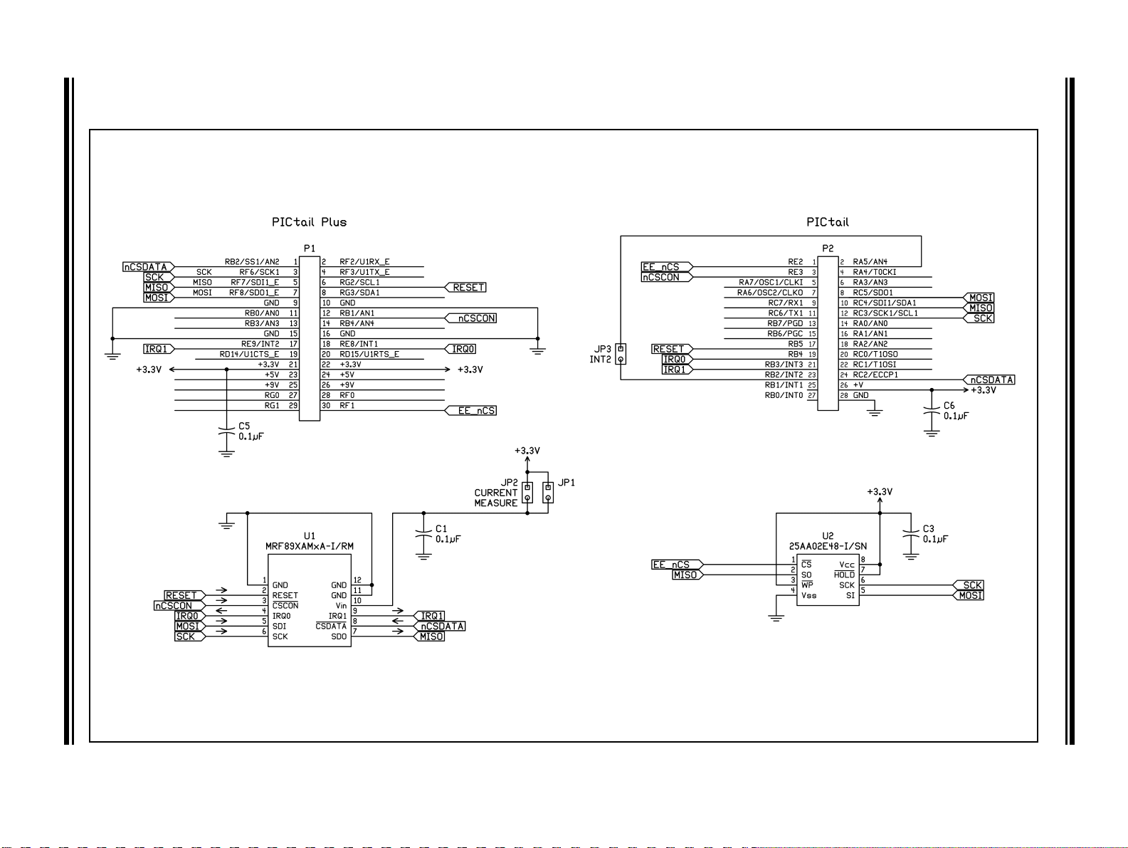
A.2 MRF89XAMxA PICtail/PICtail PLUS DAUGHTER BOARD SCHEMATIC
FIGURE A-1: MRF89XAMxA PICtail™/PICtail PLUS DAUGHTER BOARD SCHEMATIC
MRF89XAMxA PICtail™/PICtail Plus Daughter Board User’s Guide
Page 17
MRF89XAMxA PICtail/PICtail Plus Daughter Board Schematic
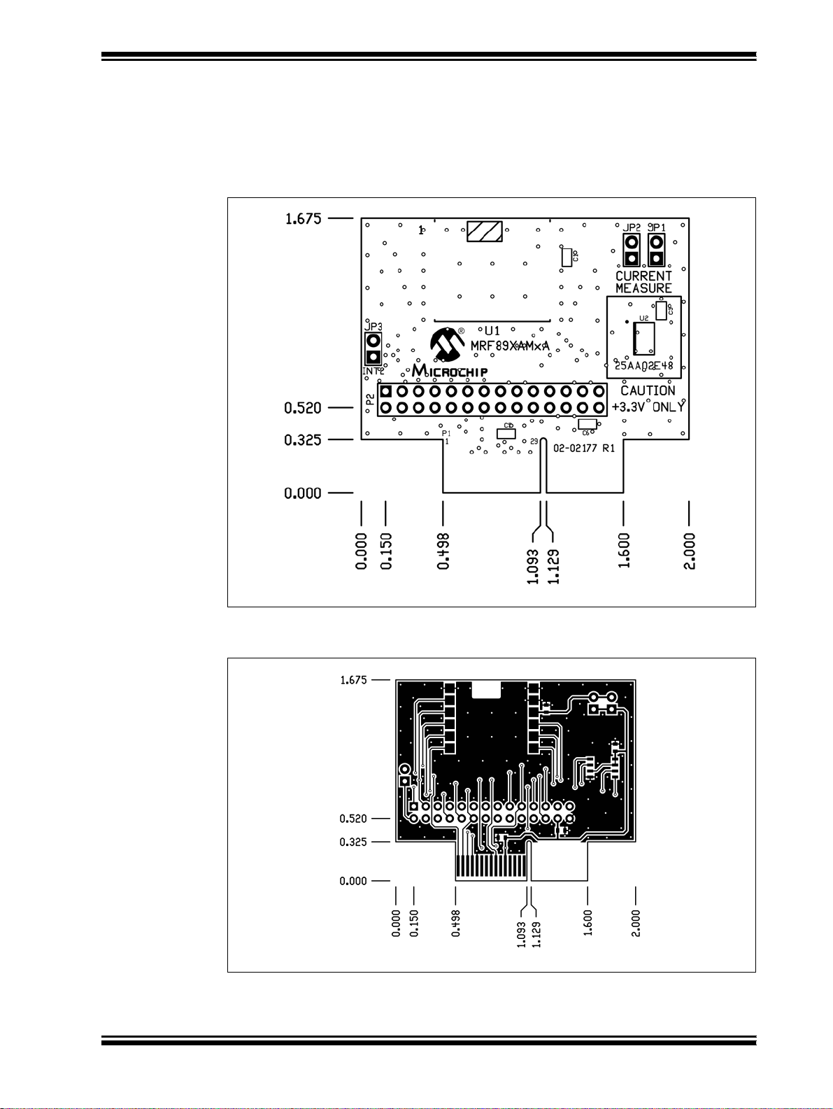
A.3 MRF89XAMxA PICtail/PICtail PLUS DAUGHTER BOARD PCB LAYOUT
The MRF89XAMxA PICtail/PICtail Plus Daughter Board is a 2-layer, FR4, 0.062 inch,
plated through hole PCB construction.
FIGURE A-2: MRF89XAMxA PICtail™/PICtail PLUS DAUGHTER BOARD
TOP SILKSCREEN
FIGURE A-3: MRF89XAMxA PICtail™/PICtail PLUS DAUGHTER BOARD
TOP COPPER
© 2011 Microchip Technology Inc. DS70653A-page 17
Page 18
MRF89XAMxA PICtail™/PICtail Plus Daughter Board User’s Guide
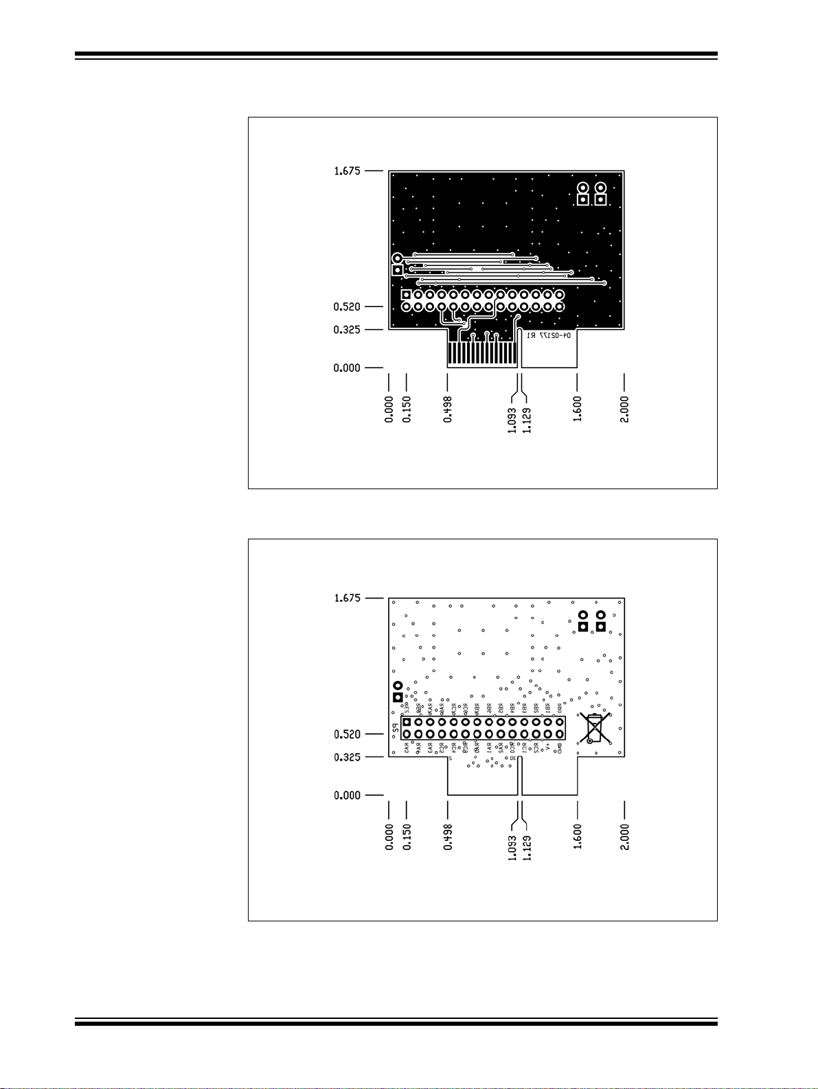
FIGURE A-4: MRF89XAMxA PICtail™/PICtail PLUS DAUGHTER
BOARD BOTTOM COPPER
FIGURE A-5: MRF89XAMxA PICtail™/PICtail PLUS DAUGHTER
BOARD BOTTOM SILKSCREEN
DS70653A-page 18 © 2011 Microchip Technology Inc.
Page 19

MRF89XAMxA PICtail/PICtail Plus Daughter Board Schematic
A.4 MRF89XAMxA PICtail/PICtail PLUS DAUGHTER BOARD BILL OF
MATERIALS
TABLE A-1: MRF89XAMxA PICtail™/PICtail PLUS DAUGHTER BOARD BILL OF MATERIALS
Reference Value Description Vendor Vendor P/N Comments
C1, C2, C3,
C5, C6
JP1, JP2,
JP3
Shunt — Connector, Shunt,
P2 — Connector, Header,
U1 MRF89XAM8A MRF89XAM8A RF
U1 MRF89XAM9A MRF89XAM9A RF
U3 25AA02E48 EUI-48 Node Identity
0.1 µF Capacitor, Ceramic,
50V, C0G, SMT 0603
— Connector, Header,
1x2, 0.100” pitch,
0.025” sq post
0.100” pitch
2x14, 0.100” pitch,
right angle 0.390/0.230
Transceiver Module
Transceiver Module
Serial EEPROM
Panasonic ECJ-1VB1C104K Bypass capacitor
SPC Technology SPC20481 —
Sullins Connector
Solutions
Sullins Connector
Solutions
Microchip
Technology
Microchip
Technology
Microchip
Technology
STC02SYAN Shunts for JP1
and JP3
GBC14DBDN —
MRF89XAM8A-I/RM Populated only
on 868 MHz
Daughter Board
MRF89XAM9A-I/RM Populated only
on 915 MHz
Daughter Board
25AA02E48-I/SN —
© 2011 Microchip Technology Inc. DS70653A-page 19
Page 20

MRF89XAMxA PICtail™/PICtail Plus Daughter Board User’s Guide
NOTES:
DS70653A-page 20 © 2011 Microchip Technology Inc.
Page 21
Worldwide Sales and Service
AMERICAS
Corporate Office
2355 West Chandler Blvd.
Chandler, AZ 85224-6199
Tel: 480-792-7200
Fax: 480-792-7277
Technical Support:
http://support.microchip.com
Web Address:
www.microchip.com
Atlanta
Duluth, GA
Tel: 678-957-9614
Fax: 678-957-1455
Boston
Westborough, MA
Tel: 774-760-0087
Fax: 774-760-0088
Chicago
Itasca, IL
Tel: 630-285-0071
Fax: 630-285-0075
Cleveland
Independence, OH
Tel: 216-447-0464
Fax: 216-447-0643
Dallas
Addison, TX
Tel: 972-818-7423
Fax: 972-818-2924
Detroit
Farmington Hills, MI
Tel: 248-538-2250
Fax: 248-538-2260
Kokomo
Kokomo, IN
Tel: 765-864-8360
Fax: 765-864-8387
Los Angeles
Mission Viejo, CA
Tel: 949-462-9523
Fax: 949-462-9608
Santa Clara
Santa Clara, CA
Tel: 408-961-6444
Fax: 408-961-6445
Toronto
Mississauga, Ontario,
Canada
Tel: 905-673-0699
Fax: 905-673-6509
ASIA/PACIFIC
Asia Pacific Office
Suites 3707-14, 37th Floor
Tower 6, The Gateway
Harbour City, Kowloon
Hong Kong
Tel: 852-2401-1200
Fax: 852-2401-3431
Australia - Sydney
Tel: 61-2-9868-6733
Fax: 61-2-9868-6755
China - Beijing
Tel: 86-10-8528-2100
Fax: 86-10-8528-2104
China - Chengdu
Tel: 86-28-8665-5511
Fax: 86-28-8665-7889
China - Chongqing
Tel: 86-23-8980-9588
Fax: 86-23-8980-9500
China - Hong Kong SAR
Tel: 852-2401-1200
Fax: 852-2401-3431
China - Nanjing
Tel: 86-25-8473-2460
Fax: 86-25-8473-2470
China - Qingdao
Tel: 86-532-8502-7355
Fax: 86-532-8502-7205
China - Shanghai
Tel: 86-21-5407-5533
Fax: 86-21-5407-5066
China - Shenyang
Tel: 86-24-2334-2829
Fax: 86-24-2334-2393
China - Shenzhen
Tel: 86-755-8203-2660
Fax: 86-755-8203-1760
China - Wuhan
Tel: 86-27-5980-5300
Fax: 86-27-5980-5118
China - Xian
Tel: 86-29-8833-7252
Fax: 86-29-8833-7256
China - Xiamen
Tel: 86-592-2388138
Fax: 86-592-2388130
China - Zhuhai
Tel: 86-756-3210040
Fax: 86-756-3210049
ASIA/PACIFIC
India - Bangalore
Tel: 91-80-3090-4444
Fax: 91-80-3090-4123
India - New Delhi
Tel: 91-11-4160-8631
Fax: 91-11-4160-8632
India - Pune
Tel: 91-20-2566-1512
Fax: 91-20-2566-1513
Japan - Yokohama
Tel: 81-45-471- 6166
Fax: 81-45-471-6122
Korea - Daegu
Tel: 82-53-744-4301
Fax: 82-53-744-4302
Korea - Seoul
Tel: 82-2-554-7200
Fax: 82-2-558-5932 or
82-2-558-5934
Malaysia - Kuala Lumpur
Tel: 60-3-6201-9857
Fax: 60-3-6201-9859
Malaysia - Penang
Tel: 60-4-227-8870
Fax: 60-4-227-4068
Philippines - Manila
Tel: 63-2-634-9065
Fax: 63-2-634-9069
Singapore
Tel: 65-6334-8870
Fax: 65-6334-8850
Taiwan - Hsin Chu
Tel: 886-3-6578-300
Fax: 886-3-6578-370
Taiwan - Kaohsiung
Tel: 886-7-213-7830
Fax: 886-7-330-9305
Taiwan - Taipei
Tel: 886-2-2500-6610
Fax: 886-2-2508-0102
Thailand - Bangkok
Tel: 66-2-694-1351
Fax: 66-2-694-1350
EUROPE
Austria - Wels
Tel: 43-7242-2244-39
Fax: 43-7242-2244-393
Denmark - Copenhagen
Tel: 45-4450-2828
Fax: 45-4485-2829
France - Paris
Tel: 33-1-69-53-63-20
Fax: 33-1-69-30-90-79
Germany - Munich
Tel: 49-89-627-144 -0
Fax: 49-89-627-144-44
Italy - Milan
Tel: 39-0331-742611
Fax: 39-0331-466781
Netherlands - Drunen
Tel: 31-416-690399
Fax: 31-416-690340
Spain - Madrid
Tel: 34-91-708-08-90
Fax: 34-91-708-08-91
UK - Wokingham
Tel: 44-118-921-5869
Fax: 44-118-921-5820
08/04/10
DS70653A-page 21 © 2011 Microchip Technology Inc.
 Loading...