

Page 1

MPLAB® XC8 C Compiler
User’s Guide
2012 Microchip Technology Inc. DS52053B
Page 2

Note the following details of the code protection feature on Microchip devices:
YSTEM
CERTIFIED BY DNV
== ISO/TS 16949 ==
• Microchip products meet the specification contained in their particular Microchip Data Sheet.
• Microchip believes that its family of products is one of the most secure families of its kind on the market today, when used in the
intended manner and under normal conditions.
• There are dishonest and possibly illegal methods used to breach the code protection feature. All of these methods, to our
knowledge, require using the Microchip products in a manner outside the operating specifications contained in Microchip’s Data
Sheets. Most likely, the person doing so is engaged in theft of intellectual property.
• Microchip is willing to work with the customer who is concerned about the integrity of their code.
• Neither Microchip nor any other semiconductor manufacturer can guarantee the security of their code. Code protection does not
mean that we are guaranteeing the product as “unbreakable.”
Code protection is constantly evolving. We at Microchip are committed to continuously improving the code protection features of our
products. Attempts to break Microchip’s code protection feature may be a violation of the Digital Millennium Copyright Act. If such acts
allow unauthorized access to your software or other copyrighted work, you may have a right to sue for relief under that Act.
Information contained in this publication regarding device
applications and t he lik e is provided only for your convenience
and may be su perseded by upda t es . It is y our responsibility to
ensure that your application meets with your specifications.
MICROCHIP MAKES NO REPRESENTATIONS OR
WARRANTIES OF ANY KIND WHETHER EXPRESS OR
IMPLIED, WRITTEN OR ORAL, STATUTORY OR
OTHERWISE, RELATED TO THE INFORMATION,
INCLUDING BUT NOT LIMITED TO ITS CONDITION,
QUALITY, PERFORMANCE, MERCHANTABILITY OR
FITNESS FOR PURPOSE. Microchip disclaims all liability
arising from this information and its use. Use of Microchip
devices in life supp ort and/or safety ap plications is entir ely at
the buyer’s risk, and the buyer agrees to defend, indemnify and
hold harmless M icrochip from any and all dama ges, claims,
suits, or expenses re sulting from such use. No licens es are
conveyed, implicitly or otherwise, under any Microchip
intellectual property rights.
Trademarks
The Microchip name and logo, the Microchip logo, dsPIC,
K
EELOQ, KEELOQ logo, MPLAB, PIC, PICmicro, PICSTART,
32
PIC
logo, rfPIC and UNI/O are registered trademarks of
Microchip Technology Incorporated in the U.S.A. and other
countries.
FilterLab, Hampshire, HI-TECH C, Linear Active Thermistor,
MXDEV, MXLAB, SEEVAL and The Embedded Control
Solutions Company are registered trademarks of Microchip
Technology Incorporated in the U.S.A.
Analog-for-the-Digital Age, Application Maestro, chipKIT,
chipKIT logo, CodeGuard, dsPICDEM, dsPICDEM.net,
dsPICworks, dsSPEAK, ECAN, ECONOMONITOR,
FanSense, HI-TIDE, In-Circuit Serial Programming, ICSP,
Mindi, MiWi, MPASM, MPLAB Certified logo, MPLIB,
MPLINK, mTouch, Omniscient Code Generation, PICC,
PICC-18, PICDEM, PICDEM.net, PICkit, PICtail, REAL ICE,
rfLAB, Select Mode, Total Endurance, TSHARC,
UniWinDriver, WiperLock and ZENA are trademarks of
Microchip Technology Incorporated in the U.S.A. and other
countries.
SQTP is a service mark of Microchip Technology Incorporated
in the U.S.A.
All other trademarks mentioned herein are property of their
respective companies.
© 2012, Microchip Technology Incorporated, Printed in the
U.S.A., All Rights Reserved.
Printed on recycled paper.
QUALITY MANAGEMENT S
DS52053B-page 2 2012 Microchip Technology Inc.
ISBN: 978-1-62076-375-9
Microchip received ISO/TS-16949:2009 certification for its worldwide
headquarters, design and wafer fabrication facilities in Chandler and
Tempe, Arizona; Gresham, Oregon and design centers in California
and India. The Company’s quality system processes and procedures
are for its PIC
devices, Serial EEPROMs, microperipherals, nonvolatile memory and
analog products. In addition, Microchip’s quality system for the design
and manufacture of development systems is ISO 9001:2000 certified.
®
MCUs and dsPIC® DSCs, KEELOQ
®
code hopping
Page 3

MPLAB® XC8 C COMPILER
USER’S GUIDE
Table of Contents
Preface ...........................................................................................................................7
Chapter 1. Compiler Overview
1.1 Introduction ...................................................................................................11
1.2 Compiler Des c ription and Do cu mentation ......... ... ............. .. .. .............. .. ....... 11
1.3 Device De s cr ip t io n .............. ......................................................................... 12
Chapter 2. Common C Interface
2.1 Introduction ...................................................................................................13
2.2 Background – The Desire for Portable Code ...............................................13
2.3 Using the CC I .. .. .. ......................................................................................... 16
2.4 ANSI Standard Refinement ..........................................................................17
2.5 ANSI Standard Extensions ...........................................................................25
2.6 Compiler Fe a tu r e s ............ ... ....................................................... .................. 39
Chapter 3. How To’s
3.1 Introduction ...................................................................................................41
3.2 Installing and Activating the Compiler .......... .................... .................... ........41
3.3 Invoking th e C o m p ile r ....... ............................................................................ 43
3.4 Writing Source Code ....................................................................................46
3.5 Getting My A p p lic a tion to Do What I W a nt .. ............. .. ... ............. .. .. ............. . 56
3.6 Understanding the Compilation Process ................................ ......................60
3.7 Fixing Code That Does Not Work .................................................. ...............67
Chapter 4. XC8 Command-line Driver
4.1 Introduction ...................................................................................................71
4.2 Invoking th e C o m p ile r ....... ............................................................................ 72
4.3 The Compilation Sequence ..........................................................................75
4.4 Runtime File s ............. ................................................................................. . 81
4.5 Compiler Ou t p u t ......... .. ................................................................................ 84
4.6 Compiler Messages ......................................................................................86
4.7 XC8 Driver O p ti on s ............. .................................................................. .. .. ... 91
4.8 Option Desc r ip tions ...................................................................................... 92
4.9 MPLAB IDE V8 U n iv e rs a l T o o ls u ite E q u iv a le nts ...... .................................. 117
4.10 MPLAB X Un iv e rs a l T o olsuite Equiva le n ts ............................................... 124
Chapter 5. C Language Features
5.1 Introduction .................................................................................................131
5.2 ANSI C Stan dar d Iss u e s ............. ... ............................................................ 131
5.3 Device-R e la te d F e a tu re s ......... ................................................................... 133
5.4 Supported Data Types and Variables ........................................................143
5.5 Memory Allocation and Access ..................................................................165
2012 Microchip Technology Inc. DS52053B-page 3
Page 4

MPLAB® XC8 C Compiler User’s Guide
5.6 Operators and Statements .........................................................................179
5.7 Register U s a g e . .. ........................................................................................ 181
5.8 Function s .... .. .............................................................................................. 182
5.9 Interrupts ............... .. ................................................................................... 189
5.10 Main, Ru n time Startup and R e s e t ............................................................ 194
5.11 Library R o u tin es ........... .................................................................... ........ 198
5.12 Mixing C and Assembly Code .............................................. ....................200
5.13 Optim iz a tio n s .... ................ ........................................................................ 208
5.14 Prepro c e s si n g .......................................................................................... 210
5.15 Linkin g P ro g r a m s ...... ................................................................... .. .. ........ 222
Chapter 6. Macro Assembler
6.1 Introduction .................................................................................................241
6.2 Assembler Usage .......................................................................................241
6.3 Options ....................................................................................................... 242
6.4 MPLAB XC8 Assembly Language ..............................................................246
6.5 Assembly- L e ve l Optimization s ........ ........................................................... 268
6.6 Assembly L is t F ile s .. ................................................................................... 269
Chapter 7. Linker
7.1 Introduction .................................................................................................277
7.2 Operatio n .................................................................................................... 277
7.3 Relocation and Psects ................................................................................285
7.4 Map Files .... .. .. ............................................................................................ 2 8 6
Chapter 8. Utilities
8.1 Introduction .................................................................................................291
8.2 Librarian ............................................................................................... .. ... . 291
8.3 OBJTOHEX ........ ........................................................................................ 295
8.4 CREF ... .. ............................. ........................................................................ 297
8.5 CROMWEL L ........................................... .................................................... 3 0 0
8.6 HEXMATE ........ .......................................................................................... 30 3
Appendix A. Library Functions
Appendix B. Erro r and Warning Messages
Appendix C. Implementation-Defined Behavior
C.1 Translati o n (G.3 .1) ............................ ......................................................... 479
C.2 Environme n t (G.3.2) ........ ....................................... ... .. .............................. 479
C.3 Identifiers (G.3.3) ....................................................................................... 480
C.4 Character s (G.3.4) ............. .. ...................................................................... 480
C.5 Integers (G.3 .5 ) ..................................................... ..................................... 48 1
C.6 Floating- P oin t (G.3.6) ........ ........................................................................ 482
C.7 Arrays and P o in te r s (G .3 . 7 ) ........ ............................................................... 482
C.8 Register s (G.3.8) ........ ... ............................................................................ 48 2
C.9 Structures, Unions, Enumerations, and Bit-Fields (G.3.9) ......................... 483
C.10 Qualifiers (G .3.10) ......... .......................................................................... 483
C.11 Declara to r s (G .3 . 1 1) ................................................................. ... .. .......... 48 3
DS52053B-page 4 2012 Microchip Technology Inc.
Page 5

C.12 Statem e nt s (G.3 .12) .... .. .......................................................................... 483
C.13 Preproce s s in g Di re c tives (G.3.13) .......... .. ............................................... 484
C.14 Library F u n ct io n s (G .3 . 1 4 ) .. .. ........................................ .. .. ....................... 485
Glossary .....................................................................................................................487
Index ...........................................................................................................................507
Worldwide Sales and Service ..................................................................................518
2012 Microchip Technology Inc. DS52053B-page 5
Page 6

MPLAB® XC8 C Compiler User’s Guide
NOTES:
DS52053B-page 6 2012 Microchip Technology Inc.
Page 7

MPLAB® XC8 C COMPILER
USER’S GUIDE
Preface
NOTICE TO CUSTOMERS
All documentation becomes dated, and this manual is no exception. Microchip tools and
documentation are constantly evolving to meet customer needs, so some actual dialogs
and/or tool descriptions may differ from those in this document. Please refer to our web site
(www.microchip.com) to obtain the latest documentation available.
Documents are identified with a “DS” number. This number is located on the bottom of each
page, in front of the p age number. The numbering convention for the DS number is
“DSXXXXXA”, where “XXXXX” is the document number and “A” is the revision level of the
document.
For the most up-to-date information on development tools, see the MPLAB
Select the Help menu, and then Topics to open a list of available online help files.
INTRODUCTION
®
IDE online help.
This chapter contains general information that will be useful to know before using the
MPLAB
• Document Layout
• Conventions Used in this Guide
• Warranty Registration
• Recommended Reading
• The Microchip Web Site
• Development Systems Customer Change Notification Service
• Customer Support
• Document Revision History
DOCUMENT LAYOUT
This document describes how to use the MPLAB XC8 C Compiler. The manual layout
is as follows:
• Chapter 1. Compiler Overv iew
• Chapter 3. How To’s
• Chapter 4. XC8 Command-line Driver
• Chapter 5. C Language Featur es
• Chapter 6. Macro Assembler
• Chapter 7. Linker
• Chapter 8. Utilities
• Appendix A. Library Functions
• Appendix B. Error and Warning Messages
• Appendix C. Implementation-Defined Behavior
• Glossary
• Index
®
XC8 C Compiler User’s Guide. Items discussed in this chapter include:
2012 Microchip Technology Inc. DS52053B-page 7
Page 8
MPLAB® XC8 C Compiler User’s Guide
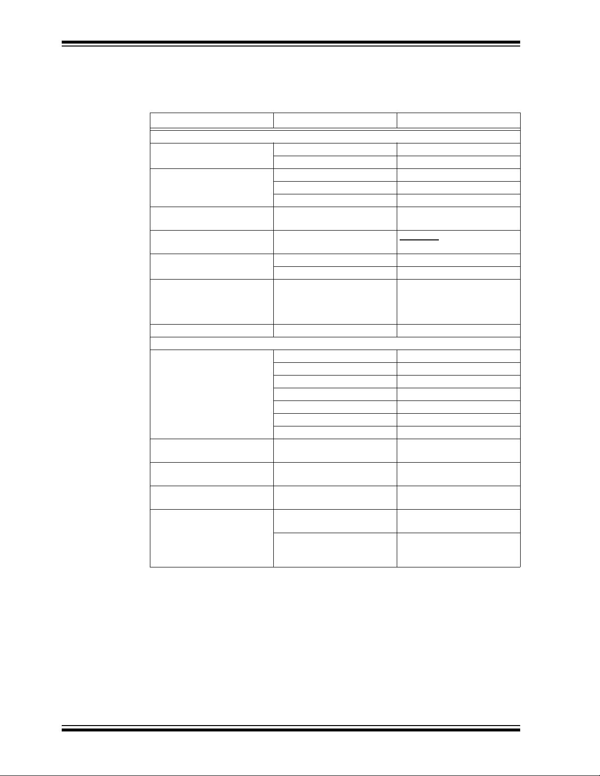
CONVENTIONS USED IN THIS GUIDE
This manual uses the following docum entat io n conven tion s:
DOCUMENTATION CONVENTIONS
Description Represents Examples
Arial font:
Italic chara c ters Referenced books MPLAB
Emphasized text ...is the only compiler...
Initial caps A window the Output window
A dialog the Settings dialog
A menu selection select Enable Programmer
Quotes A field name in a window or
dialog
Underlined, italic text with
right angle bracket
Bold characters A dialog button Click OK
N‘Rnnnn A number in verilog format,
Text in angle brac kets < > A key on the keyboard Press <Enter>, <F1>
Courier New font:
Plain Courier New Sample source code #define START
Italic Courier New A variable argument file.o, where file can be
Square brackets [ ] Optional arguments mcc18 [options] file
Curly brackets and pipe
character: { | }
Ellipses... Replaces r epeated text var_name [,
A menu path File>Save
A tab Click the Power tab
where N is the tota l number of
digits, R is th e radi x and n is a
digit.
Filenames autoexec.bat
File paths c:\mcc18\h
Keywords _asm, _endasm, static
Command-line options -Opa+, -Opa-
Bit values 0, 1
Constants 0xFF, ‘A’
Choice of mut ually exclus ive
arguments; an OR selection
Represents code supplied by
user
®
IDE User’s Guide
“Save project before build”
4‘b0010, 2‘hF1
any valid filename
[options]
errorlevel {0|1}
var_name...]
void main (void)
{ ...
}
WARRANTY REGISTRATION
Please complete the enclosed Warranty Registration Card and mail it promptly.
Sending in the Warranty Registration Card entitles users to receive new product
updates. Interim software releases are available at the Microchip web site.
RECOMMENDED READING
This user’s guide describes how to use Chapter Name. Other useful documents are
listed below. The following Microchip documents are available and recommended as
supplemental reference resources.
DS52053B-page 8 2012 Microchip Technology Inc.
Page 9

Readme for Chapter Name
For the latest information on using Chapter Name, read the “Readme for Chapter
Name.txt” file (an ASCII text file) in the Readmes subdirectory of the MPLAB
installation directory. The Readme file contains update information and known issues
that may not be included in this user’s guide.
Readme Files
For the latest information on using other tools, read the tool-specific Readme files in
the Readmes subdirectory of the MPLAB IDE installation directory. The Readme files
contain update information and known issues that may not be included in this user’s
guide.
THE MICROCHIP WEB SITE
Microchip provides online support via our web site at www.microchip.com. This web
site is used as a means to make files and information easily available to customers.
Accessible by using your favorite Internet browser, the web site contains the following
information:
• Product Support – Data sheets and errata, application notes and sample
programs, design resources, user’s guides and hardware support documents,
latest software releases and archived software
• General Technical Support – Frequently Asked Questions (FAQs), technical
support requests, online discussion groups, Microchip consultant program
member listing
• Business of Microchip – Product selector and ordering guides, latest Microchip
press releases, listing of seminars and events, listings of Microchip sales offices,
distributors and factory representatives
Preface
®
IDE
DEVELOPMENT SYSTEMS CUSTOMER CHANGE NOTIFICATION SERVICE
Microchip’s customer notification service helps keep customers current on Microchip
products. Subscribers will receive e-mail notification whenever there are changes,
updates, revisions or errata related to a specified product family or development tool of
interest.
To register, access the Microchip web site at www.microchip.com, click on Customer
Change Notification and follow the registration instructions.
The Development Systems product group categories are:
• Compilers – The latest information on Microchip C compilers and other language
tools. These include the MPLAB
and MPLAB
®
ASM30 assemblers; MPLINK™ and MPLAB LINK30 object linkers;
and MPLIB™ and MPLAB
• Emulators – The latest information on Microchip in-circuit emulators.This
includes the MPLAB
®
ICE 2000 and MPLAB ICE 4000.
• In-Circuit Debuggers – The latest information on the Microchip In-Circuit
Debugger, MPLAB
• MPLAB
®
IDE – The latest information on Microchip MPLAB IDE, the Windows®
®
ICD 2.
Integrated Development Environment for development systems tools. This list is
focused on the MPLAB
®
IDE, MPLAB® SIM simulator, MPLAB® IDE Project Man-
ager and general editing and debugging features.
• Programmers – The latest information on Microchip programmers. These include
the MPLAB
®
PM3 and PRO MATE® II device programmers and the PICSTART®
Plus and PICkit™ 1 development programmers.
®
C18 and MPLAB® C30 C compilers; MPASM™
®
LIB30 object librarians.
2012 Microchip Technology Inc. DS52053B-page 9
Page 10

MPLAB® XC8 C Compiler User’s Guide
CUSTOMER SUPPORT
Users of Microchip products can receive assistance through several channels:
• Distributor or Representative
• Local Sales Office
• Field Application Engineer (FAE)
• Technical Support
Customers should contact their distributor, representative or field application engineer
(FAE) for support. Local sales offices are also available to help customers. A listing of
sales offices and locations is included in the back of this document.
Technical support is available through the web site at: http://support.microchip.com
DOCUMENT REVISION HISTORY
Revision B (July 2012)
• Added 'how tos' chapter.
• Expanded section relating to PIC18 erratas.
• Updated the section relating to compiler optimization settings.
• Updated MPLAB v8 and MPLAB X IDE project option dialogs.
• Added sections describing PIC18 far qualifier and inline function qualifier.
• Expanded section describing the operation of the main() function
• Expanded information about equivalent assembly symbols for Baseline parts.
• Updated the table of predefined macro symbols.
• Added section on
• Added sections to do with inline-ing functions
• Updated diagrams and text associated with call graphs in the list file
• Updated library function section to be consistent with packaged libraries
• Added new compiler warnings and errors.
• Added new chapter describing the Common Compiler Interface Standard (CCI)
#pragma addrqual
Revision A (February 2012)
Initial release of this docu ment.
DS52053B-page 10 2012 Microchip Technology Inc.
Page 11

MPLAB® XC8 C COMPILER
Chapter 1. Compiler Overview
1.1 INTRODUCTION
This chapter is an overview of the MPLAB XC8 C Compiler, including these topics.
• Compiler Description and Documentation
• Device Description
1.2 COMPILER DESCRIPTION AND DOCUMENTATION
USER’S GUIDE
The MPLAB® XC8 C Compiler is a free-standing, optimizing ANSI C compiler. It supports all 8-bit PIC
as well as the PIC14000 device.
The compiler is available for several popular operating systems, including 32- and
64-bit Windows
The compiler is available in three operating modes: Free, Standard or PRO. The Standard and PRO operating modes are licensed modes and require a serial number to
enable them. Free mode is available for unlicensed customers. The basic compiler
operation, supported devices and available memory are identical across all modes.
The modes only differ in the level of optimization employed by the compiler.
®
microcontrollers: PIC10, PIC12, PIC16 and PIC18 series devices,
®
, Linux and Apple OS X.
1.2.1 Conventions
Throughout this manual, the term “compiler” is used. It can refer to all, or a subset of,
the collection of applications that comprise the MPLAB XC8 C Compiler. When it is not
important to identify which application performed an action, it will be attributed to the
compiler.
Likewise, “compiler” is often used to refer to the command-line driver. Although specifically, the driver for the MPLAB XC8 C Compiler package is called xc8. The driver and
its options are discussed in Section 4.7 “XC8 Driver Options”. Accordingly, “compiler
options” commonly relates to command-line driver options.
In a similar fashion, “compilation” refers to all or a selection of steps involved in
generating source code into an executable binary image.
2012 Microchip Technology Inc. DS52053B-page 11
Page 12

MPLAB® XC8 C Compiler User’s Guide
1.3 DEVICE DESCRIPTION
This compiler supports 8-bit Microchip PIC devices with baseline, Mid-Range,
Enhanced Mid-Range, and PIC18 cores. The following descriptions indicate the
distinctions within those device cores:
The baseline core uses a 12-bit-wide instruction set and is available in PIC10, PIC12
and PIC16 part numbers.
The Mid-Range core uses a 14-bit-wide instruction set that includes more instructions
than the baseline core. It has larger data memory banks and program memory pages,
as well. It is available in PIC12, PIC14 and PIC16 part numbers.
The Enhanced Mid-Range core also uses a 14-bit-wide instruction set, but incorporates
additional instructions and features. There are both PIC12 and PIC16 part numbers
that are based on the Enhanced Mid-Range core.
The PIC18 core instruction set is 16-bits wide and features additional instructions and
an expanded register set. PIC18 core devices have part numbers that begin with
PIC18.
The compiler takes advantage of the target device’s instruction set, addressing modes
memory and registers whenever possible.
See Section 4.8.21 “--CHIPINFO: Display List of Supported Devices” for
information on finding the full list of devices supported by the compiler.
DS52053B-page 12 2012 Microchip Technology Inc.
Page 13

Chapter 2. Common C Interface
2.1 INTRODUCTION
The Common C Interface (CCI) is available with all MPLAB XC C compilers and is
designed to enhance code portability between these compilers. For example,
CCI-conforming code would make it easier to port from a PIC18 MCU using the MPLAB
XC8 C compiler to a PIC24 MCU using the MPLAB XC16 C compiler.
The CCI assumes that your source code already conforms to the ANSI Standard. If you
intend to use the CCI, it is your responsibility to write code that conforms. Legacy projects will need to be migrated to achieve conformance. A compiler option must also be
set to ensure that the operation of the compiler is consistent with the interface when the
project is built.
The following topics are examined in this chapter of the MPLAB XC8 C Compiler User’s
Guide:
• ANSI Standard Extensions
• Using the CCI
• ANSI Standard Refinement
• ANSI Standard Extensions
MPLAB® XC8 C COMPILER
USER’S GUIDE
2.2 BACKGROUND – THE DESIRE FOR PORTABLE CODE
All programmers want to write portable source code.
Portability means that the same source code can be compiled and run in a different
execution environment than that for which it was written. Rarely can code be one hundred percent portable, but the more tolerant it is to change, the less time and effort it
takes to have it running in a new environment.
Embedded engineers typically think of code portability as being across target devices,
but this is only part of the situation. The same code could be compiled for the same
target but with a different compiler. Differences between those compilers might lead to
the code failing at compile time or runtime, so this must be considered as well.
Y ou may only write code for one target device and only use one brand of compiler, but
if there is no regulation of the compiler’s operation, simply updating your compiler
version may change your code’s behavior.
Code must be portable across targets, tools, and time to be truly flexible.
Clearly, this portability cannot be achieved by the programmer alone, since the com-
piler vendors can base their products on different technologies, implement different features and code syntax, or improve the way their product works. Many a great compiler
optimization has broken many an unsuspecting project.
Standards for the C language have been developed to ensure that change is managed
and code is more portable. The American National Standards Institute (ANSI) publishes standards for many disciplines, including programming languages. The ANSI C
Standard is a universally adopted standard for the C programming language.
2012 Microchip Technology Inc. DS52053A-page 13
Page 14

MPLAB® XC8 C Compiler User’s Guide
2.2.1 The ANSI Standard
The ANSI C Standard has to reconcile two opposing goals: freedom for compilers vendors to target new devices and improve code generation, with the known functional
operation of source code for programmers. If both goals can be met, source code can
be made portable.
The standard is implemented as a set of rules which detail not only the syntax that a
conforming C program must follow, but the semantic rules by which that program will
be interpreted. Thus, for a compiler to conform to the standard, it must ensure that a
conforming C program functions as described by the standard.
The standard describes implementation, the set of tools and the runtime environment
on which the code will run. If any of these change, e.g., you build for, and run on, a different target device, or if you update the version of the compiler you use to build, then
you are using a different implementation.
The standard uses the term behavior to mean the external appearance or action of the
program. It has nothing to do with how a program is encoded.
Since the standard is trying to achieve goals that could be construed as conflicting,
some specifications appear somewhat vague. For example, the standard states that an
int type must be able to hold at least a 16-bit value, but it does not go as far as saying
what the size of an int actually is; and the action of right-shifting a signed integer can
produce different results on different implementations; yet, these different results are
still ANSI C compliant.
If the standard is too strict, device architectures may not allow the compiler to conform.
But, if it is too weak, programmers would see wildly differing results within different
compilers and architectures, and the standard would loose its effectiveness.
The standard organizes source code whose behavior is not fully defined into groups
that include the following behaviors:
Implementation-defined behavior
This is unspecified behavior where each implementation documents how the choice
is made.
Unspecified behavior
The standard provides two or more possibilities and imposes no further requirements
on which possibility is chos en in any part ic ula r instance.
Undefined behavior
This is behavior for which the standard imposes no requirements.
1
Code that strictly conforms to the standard does not produce output that is dependent
on any unspecified, undefined, or implementation-defined behavior. The size of an
int, which we used as an example earlier, falls into the category of behavior that is
defined by implementation. That is to say, the size of an int is defined by which compiler is being used, how that compiler is being used, and the device that is being targeted.
All the MPLAB XC compilers conform to the ANS X3.159-1989 Standard for programming languages (with the exception of the XC8 compiler’s inability to allow recursion,
as mentioned in the footnote). This is commonly called the C89 Standard. Some features from the later standard, C99, are also supported.
1. Case in point: The mid-range PIC® microcontrollers do not have a data stack. Because a compiler
targeting this device cannot implement recursion, it (strictly speaking) cannot conform to the ANSI
C Standard. This example illustrate a situation in which the standard is too strict for mid-range
devices and tools.
DS52053A-page 14 2012 Microchip Technology Inc.
Page 15

Common C Interface
For freestanding implementations – or for what we typically call embedded applications
– the standard allows non-standard extensions to the language, but obviously does not
enforce how they are specified or how they work. When working so closely to the
device hardware, a programmer needs a means of specifying device setup and interrupts, as well as utilizing the often complex world of small-device memory
architectures. This cannot be offered by the standard in a consistent way.
While the ANSI C Standard provides a mutual understanding for programmers and
compiler vendors, programmers need to consider the implementation-defined behavior
of their tools and the probability that they may need to use extensions to the C language
that are non-standard. Both of these circumstances can have an impact on code portability.
2.2.2 The Common C Interface
The Common C Interface (CCI) supplements the ANSI C Standard and makes it easier
for programmers to achieve consistent outcomes on all Microchip devices when using
any of the MPLAB XC C compilers.
It delivers the following improvements, all designed with portability in mind.
Refinement of the ANSI C Standard
The CCI documents specific behavior for some code in which actions are implemen-
tation-defined behavior under the ANSI C Standard. For example, the result of
right-shifting a signed integer is fully defined by the CCI. Note that many
implementation-defined items that closely couple with device characteristics, such as
the size of an int, are not defined by the CCI.
Consistent syntax for non-standard extensions
The CCI non-standard extensions are mostly implemented using keywords with a uni-
form syntax. They replace keywords, macros and attributes that are the native compiler implementation. The interpretation of the keyword may differ across each compiler, and any arguments to the keywords may be device specific.
Coding guidelines
The CCI may indicate advice on how code should be written so that it can be ported
to other devices or compilers. While you may choose not to follow the advice, it will
not conform to the CCI.
2012 Microchip Technology Inc. DS52053A-page 15
Page 16

MPLAB® XC8 C Compiler User’s Guide
2.3 USING THE CCI
The CCI allows enhanced portability by refining implementation-defined behavior and
standardizing the syntax for extensions to the language.
The CCI is something you choose to follow and put into effect, thus it is relevant for new
projects, although you may choose to modify existing projects so they conform.
For your project to conform to the CCI, you must do the following things.
Enable the CCI
Select the MPLAB IDE widget Use CCI Syntax
command-line option that is equivalent.
Include <xc.h> in every module
Some CCI features are only enabled if this header is seen by the compiler.
Ensure ANSI compliance
Code that does not conform to the ANSI C Standard does not confirm to the CCI.
Observe refinements to ANSI by the CCI
Some ANSI implementation-defined behavior is defined explicitly by the CCI.
Use the CCI extensions to the language
Use the CCI extensions rather than the native language extensions
in your project, or use the
The next sections detail specific items associated with the CCI. These items are segregated into those that refine the standard, those that deal with the ANSI C Standard
extensions, and other miscellaneous compiler options and usage. Guidelines are indicated with these item s.
If any implementation-defined behavior or any non-standard extension is not discussed
in this document, then it is not part of the CCI. For example, GCC case ranges, label
addresses and 24-bit short long types are not part of the CCI. Programs which use
these features do not conform to the CCI. The compiler may issue a warning or error
to indicate when you use a non-CCI feature and the CCI is enabled.
DS52053A-page 16 2012 Microchip Technology Inc.
Page 17

2.4 ANSI STANDARD REFINEMENT
The following topics describe how the CCI refines the implementation-defined
behaviors outlined in the ANSI C Standard.
2.4.1 Source File Encoding
Under the CCI, a source file must be written using characters from the 7-bit ASCII set.
Lines may be terminated using a line feed ('\n') or carriage return ('\r') that is immediately followed by a line feed. Escaped characters may be used in character constants
or string literals to represent extended characters not in the basic character set.
2.4.1.1 EXAMPLE
The following shows a string constant being defined that uses escaped characters.
const char myName[] = "Bj\370rk\n";
2.4.1.2 DIFFERENCES
All compilers have used this character set.
2.4.1.3 MIGRATION TO THE CCI
No action required.
Common C Interface
2.4.2 The Prototype for main
The prototype for the main() function is
int main(void);
2.4.2.1 EXAMPLE
The following shows an example of how main() might be defined
int main(void)
{
while(1)
process();
}
2.4.2.2 DIFFERENCES
The 8-bit compilers used a void return type for this function.
2.4.2.3 MIGRATION TO THE CCI
Each program has one definition for the main() function. Confirm the return type for
main() in all projects previously compiled for 8-bit targets.
2.4.3 Header File Specification
Header file specifications that use directory separators do not conform to the CCI.
2.4.3.1 EXAMPLE
The following example sho ws two conformi ng incl ude dir ec tive s.
#include <usb_main.h>
#include "global.h"
2012 Microchip Technology Inc. DS52053A-page 17
Page 18

MPLAB® XC8 C Compiler User’s Guide
2.4.3.2 DIFFERENCES Header file specifications that use directory separators have been allowed in previous
versions of all compilers. Compatibility problems arose when Windows-style separators “\” were used and the code compiled under other host operating systems. Under
the CCI, no directory specifiers should be used.
2.4.3.3 MIGRATION TO THE CCI Any #include directiv es that use di rectory sep arators in the header fil e specifica tions
should be changed. Remove all but the header file name in the directive. Add the directory path to the compiler’s include search path or MPLAB IDE equivalent. This will force
the compiler to search the directories specified with this option.
For example, the following code:
#include <inc/lcd.h>
should be changed to:
#include <lcd.h>
and the path to the inc directory added to the compiler’s header search path in your
MPLAB IDE project properties, or on the command-line as follows:
-Ilcd
2.4.4 Include Search Paths
When you include a header file under the CCI, the file should be discoverable in the
paths searched by the compiler detailed below.
For any header files specified in angle bracket delimiters < >, the search paths should
be those specified by -I options (or the equivalent MPLAB IDE option), then the standard compiler include directories. The -I options are searched in the order in which
they are specified.
For any file specified in quote characters " ", the search paths should first be the current working directory . In the case of an MPLAB X project, the current working directory
is the directory in which the C source file is located. If unsuccessful, the search paths
should be the same directories searched when the header files is specified in angle
bracket delimiters.
Any other options to specify search paths for header files do not conform to the CCI.
2.4.4.1 EXAMPLE If including a header file as in the following directive
#include "myGlobals.h"
The header file should be locatable in the current working directory, or the paths specified by any -I options, or the standard compiler directories. If it is located elsewhere,
this does not conform to the CCI.
2.4.4.2 DIFFERENCES The compiler operation under the CCI is not changed. This is purely a coding guide line.
2.4.4.3 MIGRATION TO THE CCI Remove any option that specifies header file search paths other than the -I option (or
the equivalent MPLAB IDE option), and use the -I option in place of this. Ensure the
header file can be found in the directories specified in this section.
DS52053A-page 18 2012 Microchip Technology Inc.
Page 19

Common C Interface
2.4.5 The Number of Significant Initial Characters in an Identifier
At least the first 255 characters in an identifier (internal and external) are significant.
This extends upon the requirement of the ANSI C Standard which states a lower number of significant characters are used to identify an object.
2.4.5.1 EXAMPLE
The following example shows two poorly named variables, but names which are
considered unique under the CCI.
int stateOfPortBWhenTheOperatorHasSelectedAutomaticModeAndMotorIsRunningFast;
int stateOfPortBWhenTheOperatorHasSelectedAutomaticModeAndMotorIsRunningSlow;
2.4.5.2 DIFFERENCES
Former 8-bit compilers used 31 significant characters by default, but an option allowed
this to be extended.
The 16- and 32-bit compilers did not impose a limit on the number of significant characters.
2.4.5.3 MIGRATION TO THE CCI
No action required. You may take advantage of the less restrictive naming scheme.
2.4.6 Sizes of Types
The sizes of the basic C types, for example char, int and long, are not fully defined
by the CCI. These types, by design, reflect the size of registers and other architectural
features in the target device. They allow the device to efficiently access objects of this
type. The ANSI C Standard does, however, indicate minimum requirements for these
types, as specified in <limits.h>.
If you need fixed-size types in your project, use the types defined in <stdint.h>, e.g.,
uint8_t or int16_t. These types are consistently defined across all XC compilers,
even outside of the CCI.
Essentially, the C language offers a choice of two groups of types: those that offer sizes
and formats that are tailored to the device you are using; or those that have a fixed size,
regardless of the target.
2.4.6.1 EXAMPLE
The following example shows the definition of a variable, native, whose size will allow
efficient access on the target device; and a variable, fixed, whose size is cle a rl y i n di cated and remains fixed, even though it may not allow efficient access on every device.
int native;
int16_t fixed;
2.4.6.2 DIFFERENCES
This is consistent with previous types implemented by the compiler.
2.4.6.3 MIGRATION TO THE CCI
If you require a C type that has a fixed size, regardless of the target device, use one of
the types defined by <stdint.h>.
2012 Microchip Technology Inc. DS52053A-page 19
Page 20

MPLAB® XC8 C Compiler User’s Guide
2.4.7 Plain char Types
The type of a plain char is unsigned char. It is generally recommended that all definitions for the char type explicitly state the signedness of the object.
2.4.7.1 EXAMPLE The following example
char foobar;
defines an unsigned char object called foobar.
2.4.7.2 DIFFERENCES The 8-bit compilers have always treated plain char as an unsigned type.
The 16- and 32-bit compilers used signed char as the default plain char type. The
-funsigned-char option on those compilers changed the default type to be
unsigned char.
2.4.7.3 MIGRATION TO THE CCI Any definition of an object defined as a plain char and using the 16- or 32-bit compilers
needs review. Any plain char that was intended to be a signed quantity should be
replaced with an explicit definition, for example.
signed char foobar;
You may use the -funsigned-char option on XC16/32 to change the type of plain
char, but since this option is not supported on XC8, the code is not strictly conforming.
2.4.8 Signed Integer Representation
The value of a signed integer is determined by taking the two’s complement of the integer.
2.4.8.1 EXAMPLE The following shows a variable, test, that is assigned the value -28 decimal.
signed char test = 0xE4;
2.4.8.2 DIFFERENCES All compilers have represented signed integers in the way described in this section.
2.4.8.3 MIGRATION TO THE CCI No action required.
DS52053A-page 20 2012 Microchip Technology Inc.
Page 21

Common C Interface
2.4.9 Integer conversion
When converting an integer type to a signed integer of insufficient size, the original
value is truncated from the most-significant bit to accommodate the target size.
2.4.9.1 EXAMPLE
The following shows an assignment of a value that will be truncated.
signed char destination;
unsigned int source = 0x12FE;
destination = source;
Under the CCI, the value of destination after the alignment will be -2 (i.e., the bit
pattern 0xFE).
2.4.9.2 DIFFERENCES
All compilers have performed integer conversion in an identical fashion to that
described in this section.
2.4.9.3 MIGRATION TO THE CCI
No action required.
2.4.10 Bit-wise Operations on Signed Values
Bitwise operations on signed values act on the two’s complement representation,
including the sign bit. See also Section 2.4.11 “Right-shifting Signed Values”.
2.4.10.1 EXAMPLE
The following shows an example of a negative quantity involved in a bitwise AND operation.
signed char output, input = -13;
output = input & 0x7E;
Under the CCI, the value of output after the assignment will be 0x72.
2.4.10.2 DIFFERENCES
All compilers have performed bitwise operations in an identical fashion to that
described in this section.
2.4.10.3 MIGRATION TO THE CCI
No action required.
2.4.11 Right-shifting Signed Values
Right-shifting a signed value will involve sign extension. This will preserve the sign of
the original value.
2.4.11.1 EXAMPLE
The following shows an example of a negative quantity involved in a bitwise AND
operation.
signed char input, output = -13;
output = input >> 3;
Under the CCI, the value of output after the assignment will be -2 (i.e., the bit pattern
0xFE).
2012 Microchip Technology Inc. DS52053A-page 21
Page 22

MPLAB® XC8 C Compiler User’s Guide
2.4.11.2 DIFFERENCES All compilers have performed right shifting as described in this section.
2.4.11.3 MIGRATION TO THE CCI No action required.
2.4.12 Conversion of Union Member Accessed Using Member With Different Type
If a union defines several members of different types and you use one member identifier to try to access the contents of another (whether any conversion is applied to the
result) is implementation-defined behavior in the standard. In the CCI, no conversion is
applied and the bytes of the union object are interpreted as an object of the type of the
member being accessed, without regard for alignment or other possible invalid conditions.
2.4.12.1 EXAMPLE
The following shows an example of a union defining several members.
union {
signed char code;
unsigned int data;
float offset;
} foobar;
Code that attempts to extract offset by reading data is not guaranteed to read the
correct value.
float result;
result = foobbar.data;
2.4.12.2 DIFFERENCES
All compilers have not converted union members accessed via other members.
2.4.12.3 MIGRATION TO THE CCI
No action required.
2.4.13 Default Bit-field int Type
The type of a bit-field specified as a plain int will be identical to that of one defined
using unsigned int. This is quite different to other objects where the types int,
signed and signed int are synonymous. It is recommended that the signedness of
the bit-field be explicitly stated in all bit-field definitions.
2.4.13.1 EXAMPLE
The following shows an example of a structure tag containing bit-fields which are
unsigned integers and with the size specified.
struct OUTPUTS {
int direction :1;
int parity :3;
int value :4;
};
DS52053A-page 22 2012 Microchip Technology Inc.
Page 23

Common C Interface
2.4.13.2 DIFFERENCES The 8-bit compilers have previously issued a warning if type int was used for bit-fields,
but would implement the bit-field with an unsigned int type.
The 16- and 32-bit compilers have implemented bit-fields defined using int as having
a signed int type, unless the option -funsigned-bitfields was specified.
2.4.13.3 MIGRATION TO THE CCI Any code that defines a bit-field with the plain int type should be reviewed. If the inten-
tion was for these to be signed quantities, then the type of these should be changed to
signed int, for example, in:
struct WAYPT {
int log :3;
int direction :4;
};
the bit-field type should be changed to signed int, as in:
struct WAYPT {
signed int log :3;
signed int direction :4;
};
2.4.14 Bit-fields Straddling a Storage Unit Boundary
Whether a bit-field can straddle a storage unit boundary is implementation-defined
behavior in the standard. In the CCI, bit-fields will not straddle a storage unit boundary;
a new storage unit will be allocated to the structure, and padding bits will fill the gap.
Note that the size of a storage unit differs with each compiler as this is based on the
size of the base data type (e.g., int) from which the bit-field type is derived. On 8-bit
compilers this unit is 8-bits in size; for 16-bit compilers, it is 16 bits; and for 32-bit compilers, it is 32 bits in size.
2.4.14.1 EXAMPLE The following shows a structure containing bit-fields being defined.
struct {
unsigned first : 6;
unsigned second :6;
} order;
Under the CCI and using XC8, the storage allocation unit is byte sized. The bit-field
second, will be allocated a new storage unit since there are only 2 bits remaining in
the first storage unit in which first is allocated. The size of this structure, order, will
be 2 bytes.
2.4.14.2 DIFFERENCES This allocation is identical with that used by all previous compilers.
2.4.14.3 MIGRATION TO THE CCI No action required.
2.4.15 The Allocation Order of Bits-field
The memory ordering of bit-fields into their storage unit is not specified by the ANSI C
Standard. In the CCI, the first bit defined will be the least significant bit of the storage
unit in which it will be allocated.
2012 Microchip Technology Inc. DS52053A-page 23
Page 24

MPLAB® XC8 C Compiler User’s Guide
2.4.15.1 EXAMPLE
The following shows a structure containing bit-fields being defined.
struct {
unsigned lo : 1;
unsigned mid :6;
unsigned hi : 1;
} foo;
The bit-field lo will be assigned the least significant bit of the storage unit assigned to
the structure foo. The bit-field mid will be assigned the next 6 least significant bits, and
hi, the most significant bit of that same storage unit byte.
2.4.15.2 DIFFERENCES
This is identical with the previous operation of all compilers.
2.4.15.3 MIGRATION TO THE CCI
No action required.
2.4.16 The NULL macro
The NULL macro is defined in <stddef.h>; however, its definition is implementation-defined behavior. Under the CCI, the definition of NULL is the expression (0).
2.4.16.1 EXAMPLE
The following shows a pointer being assigned a null pointer constant via the NULL
macro.
int * ip = NULL;
The value of NULL, (0), is implicitly cast to the destination type.
2.4.16.2 DIFFERENCES
The 32-bit compilers previously assigned NULL the expression ((void *)0).
2.4.16.3 MIGRATION TO THE CCI
No action required.
2.4.17 Floating-point sizes
Under the CCI, floating-point types must not be smaller than 32 bits in size.
2.4.17.1 EXAMPLE
The following shows the definition for outY, which will be at least 32-bit in size.
float outY;
2.4.17.2 DIFFERENCES
The 8-bit compilers have allowed the use of 24-bit float and double types.
2.4.17.3 MIGRATION TO THE CCI
When using 8-bit compilers, the float and double type will automatically be made
32 bits in size once the CCI mode is enabled. Review any source code that may have
assumed a float or double type and may have been 24 bits in size.
No migration is required for other compilers.
DS52053A-page 24 2012 Microchip Technology Inc.
Page 25

2.5 ANSI STANDARD EXTENSIONS
The following topics describe how the CCI provides device-specific extensions to the
standard.
2.5.1 Generic Header File
A single header file <xc.h> must be used to declare all compiler- and device-specific
types and SFRs. You must include this file into every module to conform with the CCI.
Some CCI definitions depend on this header being seen.
2.5.1.1 EXAMPLE The following shows this header file being included, thus allowing conformance with the
CCI, as well as allowing access to SFRs.
#include <xc.h>
2.5.1.2 DIFFERENCES Some 8-bit compilers used <htc.h> as the equivalent header. Previous versions of
the 16- and 32-bit compilers used a variety of headers to do the same job.
2.5.1.3 MIGRATION TO THE CCI Change:
#include <htc.h>
used previously in 8-bit compiler code, or family-specific header files as in the following
examples:
#include <p32xxxx.h>
#include <p30fxxxx.h>
#include <p33Fxxxx.h>
#include <p24Fxxxx.h>
#include "p30f6014.h"
to:
#include <xc.h>
Common C Interface
2.5.2 Absolute addressing
Variables and functions can be placed at an absolute address by using the __at()
construct.qualifier Note that XC16/32 may require the variable or function to be placed
in a special section for absolute addressing to work. Stack-based (auto and parameter) varia bles cannot use the __at() specifier.
2.5.2.1 EXAMPLE The following shows two variables and a function being made absolute.
int scanMode __at(0x200);
const char keys[] __at(123) = { ’r’, ’s’, ’u’, ’d’};
int modify(int x) __at(0x1000) {
return x * 2 + 3;
}
2.5.2.2 DIFFERENCES The 8-bit compilers have used an @ symbol to specify an absolute address.
The 16- and 32-bit compilers have used the address attribute to specify an object’s
address.
2012 Microchip Technology Inc. DS52053A-page 25
Page 26

MPLAB® XC8 C Compiler User’s Guide
2.5.2.3 MIGRATION TO THE CCI
Avoid making objects and functions absolute if possible.
In XC8, change absolute object definitions such as the following example:
int scanMode @ 0x200;
to:
int scanMode __at(0x200);
In XC16/32, change code such as:
int scanMode __attribute__(address(0x200)));
to:
int scanMode __at(0x200);
2.5.2.4 CAVEATS
If the __at() and __section() specifiers are both applied to an object when using
XC8, the __section() specifier is currently ignored.
2.5.3 Far Objects and Functions
The __far qualifier may be used to indicate that variables or functions may be located
in ‘far memory’. Exactly what constitutes far memory is dependent on the target device,
but it is typically memory that requires more complex code to access. Expressions
involving far-qualified objects may generate slower and larger code.
Use the native keywords discussed in the Differences section to look up information on
the semantics of this qualifier.
Some devices may not have such memory implemented, in which case, use of this
qualifier will be ignored. Stack-based (auto and parameter) variables cannot use the
__far specifier.
2.5.3.1 EXAMPLE
The following shows a variable and function qualified using __far.
__far int serialNo;
__far int ext_getCond(int selector);
2.5.3.2 DIFFERENCES
The 8-bit compilers have used the qualifier far to indicate this meaning. Functions
could not be qualified as far.
The 16-bit compilers have used the far attribute with both variables and functions.
The 32-bit compilers have used the far attribute with functions, only.
DS52053A-page 26 2012 Microchip Technology Inc.
Page 27

Common C Interface
2.5.3.3 MIGRATION TO THE CCI For 8-bit compilers, change any occurrence of the far qualifier, as in the following
example:
far char template[20];
to __far, i.e., __far char template[20];
In the 16- and 32-bit compilers, change any occurrence of the far attribute, as in the
following
void bar(void) __attribute__ ((far));
int tblIdx __attribute__ ((far));
to
void __far bar(void);
int __far tblIdx;
2.5.3.4 CAVEATS None.
2.5.4 Near Objects
The __near qualifier may be used to indicate that variables or functions may be
located in ‘near memory’. Exactly what constitutes near memory is dependent on the
target device, but it is typically memory that can be accessed with less complex code.
Expressions involving near-qualified objects may be faster and result in smaller code.
Use the native keywords discussed in the Differences section to look up information on
the semantics of this qualifier.
Some devices may not have such memory implemented, in which case, use of this
qualifier will be ignored. Stack-based (auto and parameter) variables cannot use the
__near specifier.
2.5.4.1 EXAMPLE The following shows a variable and function qualified using __near.
__near int serialNo;
__near int ext_getCond(int selector);
2.5.4.2 DIFFERENCES The 8-bit compilers have used the qualifier near to indicate this meaning. Functions
could not be qualified as near.
The 16-bit compilers have used the near attribute with both variables and functions.
The 32-bit compilers have used the near attribute for functions, only.
2012 Microchip Technology Inc. DS52053A-page 27
Page 28

MPLAB® XC8 C Compiler User’s Guide
2.5.4.3 MIGRATION TO THE CCI
For 8-bit compilers, change any occurrence of the near qualifier, as in the following
example:
near char template[20];
to __near, i.e., __near char template[20];
In 16- and 32-bit compilers, change any occurrence of the near attribute, as in the fol-
lowing
void bar(void) __attribute__ ((near));
int tblIdx __attribute__ ((near));
to
void __near bar(void);
int __near tblIdx;
2.5.4.4 CAVEATS
None.
2.5.5 Persistent Objects
The __persistent qualifier may be used to indicate that variables should not be
cleared by the runtime startup code.
Use the native keywords discussed in the Differences section to look up information on
the semantics of this qualifier.
2.5.5.1 EXAMPLE
The following shows a variable qualified using __persistent.
__persistent int serialNo;
2.5.5.2 DIFFERENCES
The 8-bit compilers have used the qualifier, persistent, to indicate this meaning.
The 16- and 32-bit compilers have used the persistent attribute with variables to
indicate they were not to be cleared.
2.5.5.3 MIGRATION TO THE CCI
With 8-bit compilers, change any occurrence of the persistent qualifier, as in the following example:
persistent
char template[20];
to __persistent, i.e., __persistent char template[20];
For the 16- and 32-bit compilers, change any occurrence of the persistent attribute,
as in the following
int tblIdx __attribute__ ((persistent));
to
int __persistent tblIdx;
2.5.5.4 CAVEATS
None.
DS52053A-page 28 2012 Microchip Technology Inc.
Page 29

Common C Interface
2.5.6 X and Y Data Objects
The __xdata and __ydata qualifiers may be used to indicate that variables may be
located in special memory regions. Exactly what constitutes X and Y memory is dependent on the target device, but it is typically memory that can be accessed independently
on separate buses. Such memory is often required for some DSP instructions.
Use the native keywords discussed in the Differences section to look up information on
the semantics of these qualifiers.
Some devices may not have such memory implemented; in which case, use of these
qualifiers will be ignored.
2.5.6.1 EXAMPLE The following shows a variable qualified using __xdata, as well as another variable
qualified with __ydata.
__xdata char data[16];
__ydata char coeffs[4];
2.5.6.2 DIFFERENCES The 16-bit compilers have used the xmemory and ymemory space attribute with
variables.
Equivalent specifiers have never been defined for any other compiler.
2.5.6.3 MIGRATION TO THE CCI For 16-bit compilers, change any occurrence of the space attributes xmemory or
ymemory, as in the following example:
char __attribute__((space(xmemory)))template[20];
to __xdata, or __ydata, i.e., __xdata char template[20];
2.5.6.4 CAVEATS None.
2.5.7 Banked Data Objects
The __bank(num) qualifier may be used to indicate that variables may be located in
a particular data memory bank. The number, num, represents the bank number. Exactly
what constitutes banked memory is dependent on the target device, but it is typically a
subdivision of data memory to allow for assembly instructions with a limited address
width field.
Use the native keywords discussed in the Differences section to look up information on
the semantics of these qualifiers.
Some devices may not have banked data memory implemented, in which case, use of
this qualifier will be ignored. The number of data banks implemented will vary from one
device to another.
2.5.7.1 EXAMPLE The following shows a variable qualified using __bank().
__bank(0) char start;
__bank(5) char stop;
2012 Microchip Technology Inc. DS52053A-page 29
Page 30

MPLAB® XC8 C Compiler User’s Guide
2.5.7.2 DIFFERENCES
The 8-bit co mpile rs hav e used the fo ur qua lifie rs bank0, bank1, bank2 and bank3 to
indicate the same, albeit more limited, memory placement.
Equivalent specifiers have never been defined for any other compiler.
2.5.7.3 MIGRATION TO THE CCI
For 8-bit compilers, change any occurrence of the bankx qualifiers, as in the following
example:
bank2 int logEntry;
to __bank(), i.e., __bank(2) int logEntry;
2.5.7.4 CAVEATS
None.
2.5.8 Alignment of Objects
The __align(alignment) specifier may be used to indicate that variables must be
aligned on a memory address that is a multiple of the alignment specified. The alignment term must be a power of two. Positive values request that the object’s start
address be aligned; negative values imply the object’s end address be aligned.
Use the native keywords discussed in the Differences section to look up information on
the semantics of this specifier.
2.5.8.1 EXAMPLE
The following shows variables qualified using __align() to ensure they end on an
address that is a multiple of 8, and start on an address that is a multiple of 2,
respectively.
__align(-8) int spacer;
__align(2) char coeffs[6];
2.5.8.2 DIFFERENCES
An alignment feature has never been implemented on 8-bit compilers.
The 16- and 32-bit compilers used the aligned attribute with variables.
2.5.8.3 MIGRATION TO THE CCI
For 16- and 32-bit compilers, change any occurrence of the aligned attribute, as in
the following example:
char __attribute__((aligned(4)))mode;
to __align, i.e., __align(4) char mode;
2.5.8.4 CAVEATS
This feature is not yet implemented on XC8.
DS52053A-page 30 2012 Microchip Technology Inc.
Page 31

Common C Interface
2.5.9 EEPROM Objects
The __eeprom qualif ier may be us ed to indi cate that variable s should be positio ned in
EEPROM.
Use the native keywords discussed in the Differences section to look up information on
the semantics of this qualifier.
Some devices may not implement EEPROM. Use of this qualifier for such devices will
generate a warning. Stack-based (auto and parameter) variables cannot use the
__eeprom specifier.
2.5.9.1 EXAMPLE The following shows a variable qualified using __eeprom.
__eeprom int serialNos[4];
2.5.9.2 DIFFERENCES The 8-bit compilers have used the qualifier, eeprom, to indicate this meaning for some
devices.
The 16-bit compilers have used the space attribute to allocate variables to the memory
space used for EEPROM.
2.5.9.3 MIGRATION TO THE CCI For 8-bit compilers, change any occurrence of the eeprom qualifier, as in the following
example:
eeprom
to __eeprom, i.e., __eeprom char title[20];
For 16-bit compilers, change any occurrence of the eedata space attribute, as in the
following
int mainSw __attribute__ ((space(eedata)));
to
int __eeprom mainSw;
2.5.9.4 CAVEATS XC8 does not implement the __eeprom qualifiers for any PIC18 devices; this qualifier
will work as expected for other 8-bit devices.
char title[20];
2.5.10 Interrupt Functions
The __interrupt(type) specifier may be used to indicate that a function is to act
as an interrupt service routine. The type is a comma-separated list of keywords that
indicate information about the interrupt function.
The current interrupt types are:
<empty>
Implement the default interrupt function
low_priority
The interrupt function corresponds to the low priority interrupt source (XC8 – PIC18
only)
high_priority
The interrupt function corresponds to the high priority interrupt source (XC8)
2012 Microchip Technology Inc. DS52053A-page 31
Page 32

MPLAB® XC8 C Compiler User’s Guide
save(symbol-list)
Save on entry and restore on exit the listed symbols (XC16)
irq(irqid)
Specify the interrupt vector associated with this interrupt (XC16)
altirq(altirqid)
Specify the alternate interrupt vector associated with this interrupt (XC16)
preprologue(asm)
Specify assembly code to be executed before any compiler-generated interrupt code
(XC16)
shadow
Allow the ISR to utilise the shadow registers for context switching (XC16)
auto_psv
The ISR will set the PSVPAG register and restore it on exit (XC16)
no_auto_psv
The ISR will not set the PSVPAG register (XC16)
Use the native keywords discussed in the Differences section to look up information on
the semantics of this specifier.
Some devices may not implement interrupts. Use of this qualifier for such devices will
generate a warning. If the argument to the __interrupt specifier does not make
sense for the target device, a warning or error will be issued by the compiler.
2.5.10.1 EXAMPLE
The following shows a function qualified using __interrupt.
__interrupt(low_priority) void getData(void) {
if (TMR0IE && TMR0IF) {
TMR0IF=0;
++tick_count;
}
}
2.5.10.2 DIFFERENCES
The 8-bit compilers have used the interrupt and low_priority qualifiers to indicate this meaning for some devices. Interrupt routines were by default high priority.
The 16- and 32-bit compilers have used the interrupt attribute to define interrupt
functions.
2.5.10.3 MIGRATION TO THE CCI
For 8-bit compilers, change any occurrence of the interrupt qualifier, as in the
following examples:
void interrupt myIsr(void)
void interrupt low_priority myLoIsr(void)
to the following, respectively
void __interrupt(high_priority) myIsr(void)
void __interrupt(low_priority) myLoIsr(void)
For 16-bit compilers, change any occurrence of the interrupt attribute, as in the following example:
void __attribute__((interrupt,auto_psv,(irq(52)))) myIsr(void);
DS52053A-page 32 2012 Microchip Technology Inc.
Page 33

Common C Interface
to
void __interrupt(auto_psv,(irq(52)))) myIsr(void);
For 32-bit compilers, the __interrupt() keyword takes two parameters, the vector
number and the (optional) IPL value. Change code which uses the interrupt attribute, similar to these examples:
void __attribute__((vector(0), interrupt(IPL7AUTO), nomips16))
myisr0_7A(void) {}
void __attribute__((vector(1), interrupt(IPL6SRS), nomips16))
myisr1_6SRS(void) {}
/* Determine IPL and context-saving mode at runtime */
void __attribute__((vector(2), interrupt(), nomips16))
myisr2_RUNTIME(void) {}
to
void __interrupt(0,IPL7AUTO) myisr0_7A(void) {}
void __interrupt(1,IPL6SRS) myisr1_6SRS(void) {}
/* Determine IPL and context-saving mode at runtime */
void __interrupt(2) myisr2_RUNTIME(void) {}
2.5.10.4 CAVEATS None.
2.5.11 Packing Objects
The __pack specifier may be used to indicate that structures should not use memory
gaps to align structure members, or that individual structure members should not be
aligned.
Use the native keywords discussed in the Differences section to look up information on
the semantics of this specifier.
Some compilers may not pad structures with alignment gaps for some devices and use
of this specifier for such devices will be ignored.
2.5.11.1 EXAMPLE The following shows a structure qualified using __pack as well as a structure where
one member has been explicitly packed.
__pack struct DATAPOINT {
unsigned char type;
int value;
} x-point;
struct LINETYPE {
unsigned char type;
__pack int start;
long total;
} line;
2.5.11.2 DIFFERENCES The __pack specifier is a new CCI specifier available with XC8. This specifier has no
apparent effect since the device memory is byte addressable for all data objects.
The 16- and 32-bit compilers have used the packed attribute to indicate that a struc-
ture member was not aligned with a memory gap.
2012 Microchip Technology Inc. DS52053A-page 33
Page 34

MPLAB® XC8 C Compiler User’s Guide
2.5.11.3 MIGRATION TO THE CCI No migration is required for XC8.
For 16- and 32-bit compilers, change any occurrence of the packed attribute, as in the
following example:
struct DOT
{
char a;
int x[2] __attribute__ ((packed));
};
to:
struct DOT
{
char a;
__pack int x[2];
};
Alternatively, you may pack the entire structure, if required.
2.5.11.4 CAVEATS None.
2.5.12 Indicating Antiquated Objects
The __deprecate specifier may be used to indicate that an object has limited longevity and should not be used in new designs. It is commonly used by the compiler vendor
to indicate that compiler extensions or features may become obsolete, or that better
features have been developed and which should be used in preference.
Use the native keywords discussed in the Differences section to look up information on
the semantics of this specifier.
2.5.12.1 EXAMPLE The following shows a function which uses the __deprecate keyword.
void __deprecate getValue(int mode)
{
//...
}
2.5.12.2 DIFFERENCES No deprecate feature was implemented on 8-bit compilers.
The 16- and 32-bit compilers have used the deprecated attribute (note different spelling) to indicate that objects should be avoided if possible.
2.5.12.3 MIGRATION TO THE CCI For 16- and 32-bit compilers, change any occurrence of the deprecated attribute, as
in the following example:
int __attribute__(deprecated) intMask;
to:
int __deprecate intMask;
2.5.12.4 CAVEATS None.
DS52053A-page 34 2012 Microchip Technology Inc.
Page 35

Common C Interface
2.5.13 Assigning Objects to Sections
The __section() specifier may be used to indicate that an object should be located
in the named section (or psect, using the XC8 terminology). This is typically used when
the object has special and unique linking requirements which cannot be addressed by
existing compiler features.
Use the native keywords discussed in the Differences section to look up information on
the semantics of this specifier.
2.5.13.1 EXAMPLE The following shows a variable which uses the __section keyword.
int __section("comSec") commonFlag;
2.5.13.2 DIFFERENCES The 8-bit compilers have used the #pragma psect directive to redirect objects to a
new section, or psect. The operation of the __section() specifier is different to this
pragma in several ways, described below.
Unlike with the pragma, the new psect created with __section() does not inherit the
flags of the psect in which the object would normally have been allocated. This means
that the new psect can be linked in any memory area, including any data bank. The
compiler will also make no assumptions about the location of the object in the new section. Objects redirected to new psects using the pragma must always be linked in the
same memory area, albeit at any address in that area.
The __section() specifier allows objects that are initialized to be placed in a different
psect. Initialization of the object will still be performed even in the new psect. This will
require the automatic allocation of an additional psect (whose name will be the same
as the new psect prefixed with the letter i), which will contain the initial values. The
pragma cannot be used with objects that are initialized.
Objects allocated a different psect with __section() will be cleared by the runtime
startup code, unlike objects which use the pragma.
Y ou must reserve memory, and locate via a linker option, for any new psect created with
a __section() specifier in the current XC8 compiler implementation.
The 16- and 32-bit compilers have used the section attribute to indicate a different
destination section name. The __section() specifier works in a similar way to the
attribute.
2.5.13.3 MIGRATION TO THE CCI For XC8, change any occurrence of the #pragma psect directive, such as
#pragma psect text%%u=myText
int getMode(int target) {
//...
}
to the __section() specifier, as in
int __section ("myText") getMode(int target) {
//...
}
For 16- and 32-bit compilers, change any occurrence of the section attribute, as in
the following example:
int __attribute__((section("myVars"))) intMask;
to:
int __section("myVars") intMask;
2012 Microchip Technology Inc. DS52053A-page 35
Page 36

MPLAB® XC8 C Compiler User’s Guide
2.5.13.4 CAVEATS With XC8, the __section() specifier cannot be used with any interrupt function.
2.5.14 Specifying Configuration Bits
The #pragma config directive may be used to program the configuration bits for a
device. The pragma has the form:
#pragma config setting = state|value
where setting is a configuration setting descriptor (e.g., WDT), state is a de scriptive
value (e.g., ON) and value is a numerical value.
Use the native keywords discussed in the Differences section to look up information on
the semantics of this directive.
2.5.14.1 EXAMPLE The following shows configuration bits being specified using this pragma.
#pragma config WDT=ON, WDTPS = 0x1A
2.5.14.2 DIFFERENCES The 8-bit compilers have used the __CONFIG() macro for some targets that did not
already have support for the #pragma config.
The 16-bit compilers have used a number of macros to specify the configuration set-
tings.
The 32-bit compilers supported the use of #pragma config.
2.5.14.3 MIGRATION TO THE CCI For the 8-bit compilers, change any occurrence of the __CONFIG() macro, such as
__CONFIG(WDTEN & XT & DPROT)
to the #pragma config directive, as in
#pragma config WDTE=ON, FOSC=XT, CPD=ON
No migration is required if the #pragma config was already used.
For the 16-bit compilers, change any occurrence of the _FOSC() or _FBORPOR()
macros attribute, as in the following example:
_FOSC(CSW_FSCM_ON & EC_PLL16);
to:
#pragma config FCKSMEM = CSW_ON_FSCM_ON, FPR = ECIO_PLL16
No migration is required for 32-b it code.
2.5.14.4 CAVEATS None.
2.5.15 Manifest Macros
The CCI defines the general form for macros that manifest the compiler and target
device characteristics. These macros can be used to conditionally compile alternate
source code based on the compiler or the target device.
The macros and macro families are details in Table 2-1.
TABLE 2-1: MANIFEST MACROS DEFINED BY THE CCI
Name Meaning if defined Example
__XC__ Compiled with an MPLAB XC compiler __XC__
DS52053A-page 36 2012 Microchip Technology Inc.
Page 37

Common C Interface
TABLE 2-1: MANIFEST MACROS DEFINED BY THE CCI
Name Meaning if defined Example
__CCI__ Compiler is CCI compliant and CCI enforce-
ment is enabled
__XC##__ The specific XC comp iler u sed (## c an be 8,
16 or 32)
__DEVICEFAMILY__ The family of the selected target device __dsPIC30F__
__DEVICENAME__ The selected target device name __18F452__
2.5.15.1 EXAMPLE The following shows code which is conditionally compiled dependent on the device
having EEPROM memory.
#ifdef __XC16__
void __interrupt(__auto_psv__) myIsr(void)
#else
void __interrupt(low_priority) myIsr(void)
#endif
2.5.15.2 DIFFERENCES Some of these CCI macros are new (for example __CCI__), and others have different
names to previous symbols with identical meaning (for example __18F452 is now
__18F452__).
__CCI__
__XC8__
2.5.15.3 MIGRATION TO THE CCI Any code which uses compiler-defined macros will need review. Old macros will con-
tinue to work as expected, but they are not compliant with the CCI.
2.5.15.4 CAVEATS None.
2012 Microchip Technology Inc. DS52053A-page 37
Page 38

MPLAB® XC8 C Compiler User’s Guide
2.5.16 In-line Assembly
The asm() statement may be used to insert assembly code in-line with C code. The
argument is a C string literal which represents a single assembly instruction. Obviously,
the instructions contained in the argument are device specific.
Use the native keywords discussed in the Differences section to look up information on
the semantics of this statement.
2.5.16.1 EXAMPLE The following shows a MOVLW instruction being inserted in-line.
asm("MOVLW _foobar");
2.5.16.2 DIFFERENCES The 8-bit compilers have used either the asm() or #asm ... #endasm constructs to
insert in-line assembly code.
This is the same syntax used by the 16- and 32-bit compilers.
2.5.16.3 MIGRATION TO THE CCI For 8-bit compilers change any instance of #asm ... #endasm so that each instruction
in this #asm block is placed in its own asm() statement, for example:
#asm
MOVLW 20
MOVWF _i
CLRF Ii+1
#endasm
to
asm("MOVLW20");
asm("MOVWF _i");
asm("CLRFIi+1");
No migration is required for the 16- or 32-bit compilers.
2.5.16.4 CAVEATS None.
DS52053A-page 38 2012 Microchip Technology Inc.
Page 39

2.6 COMPILER FEATURES
The following items detail compiler options and features that are not directly associated
with source code that
2.6.1 Enabling the CCI
It is assumed you are using the MPLAB X IDE to build projects that use the CCI. The
widget in the MPLAB X IDE Project Properties to enable CCI conformance is Use CCI
Syntax in the Compiler category. A widget with the same name is available in MPLAB
IDE v8 under the Compiler tab.
If you are not using this IDE, then the command-line options are --CCI for XC8 or
-mcci for XC16/32.
2.6.1.1 DIFFERENCES This option has never been implemented previously.
2.6.1.2 MIGRATION TO THE CCI Enable the option.
2.6.1.3 CAVEATS None.
Common C Interface
2012 Microchip Technology Inc. DS52053A-page 39
Page 40

MPLAB® XC8 C Compiler User’s Guide
NOTES:
DS52053A-page 40 2012 Microchip Technology Inc.
Page 41

MPLAB® XC8 C COMPILER
Chapter 3. How To’s
3.1 INTRODUCTION
This section contains help and references for situations that are frequently encountered
when building projects for Microchip 8-bit devices. Click the links at the beginning of
each section to assist finding the topic relevant to your question. Some topics are
indexed in multiple secti ons.
Start here:
• Installing and Activating the Compiler
• Invoking the Compiler
• Writing Source Code
• Getting My Application to Do What I Want
• Understanding the Compilation Process
• Fixing Code That Does Not Work
3.2 INSTALLING AND ACTIVATING THE COMPILER
USER’S GUIDE
This section details questions that might arise when installing or activating the compiler.
• How Do I Install and Activate My Compiler?
• How Can I Tell if the Compiler has Activated Successfully?
• Can I Install More Than One Version of the Same Compiler?
3.2.1 How Do I Install and Activate My Compiler?
Installation and activation of the license are performed simultaneously by the XC compiler installer. The guide Installing and Licensing MPLAB XC C Compilers (DS52059)
is available on www.microchip.com. It provides details on single-user and network
licenses, as well as how to activate a compiler for evaluation purposes.
3.2.2 How Can I Tell if the Compiler has Activated Successfully?
If you think the compiler may not have installed correctly or is not working, it is best to
verify its operation outside of MPLAB IDE to isolate possible problems. Try running the
compiler from the command line to check for correct operation. You do not actually
have to compile code.
From your terminal or DOS-prompt, run the compiler driver xc8 (see Section 4.2
“Invoking the Compiler”) with the option --VER. This option instructs the compiler to
print version information and exit. So, under Windows, for example, type the following
line, replacing the path information with a path that is relevant to your installation.
"C:\Program Files\Microchip\xc8\v1.00\bin\xc8" --ver
The compiler should run, print an informative banner and quit. That banner indicates
the operating mode. Confirm that the operating mode is the one you requested. Note:
if it is not activated properly, the compiler will continue to operate, but only in the Free
mode. If an error is displayed, or the compiler indicates Free mode, then activation was
not successful.
2012 Microchip Technology Inc. DS52053B-page 41
Page 42

MPLAB® XC8 C Compiler User’s Guide
3.2.3 Can I Install More Than One Version of the Same Compiler?
Yes, the compilers and installation process has been designed to allow you to have
more than one version of the same compiler installed, and you can easily swap
between version by changing options in MPLAB IDE, see Section 3.3.4 “How Can I
Select Which Compiler I Want to Build With?”.
Compilers should be installed into a directory whose name is related to the compiler
version. This is reflected in the default directory specified by the installer. For example,
the 1.00 and 1.10 XC8 compilers would typically be placed in separate directories.
C:\Program Files\Microchip\xc8\v1.00\
C:\Program Files\Microchip\xc8\v1.10\
DS52053B-page 42 2012 Microchip Technology Inc.
Page 43

3.3 INVOKING THE COMPILER
This section discusses how the compiler is run, both on the command-line and from the
MPLAB IDE. It includes information about how to get the compiler to do what you want
in terms of options and the build process itself.
• How Do I Compile from Within MPLAB X IDE?
• How Do I Compile on the Command-line?
• How Do I Compile Using a Make Utility?
• How Can I Select Which Compiler I Want to Build With?
• How Can I Change the Compiler's Operating Mode?
• What Do I Need to Do When Compiling to Use a Debugger?
• How Do I Build Libraries?
• How Do I Use Library Files In My Project?
• How Do I Know What Compiler Options Are Available and What They Do?
• How Do I Know What the Build Options in MPLAB IDE do?
• What is Different About an MPLAB IDE Debug Build?
• How Do I Stop the Compiler Using Certain Memory Locations?
• What Optimizations Are Employed By The Compiler?
3.3.1 How Do I Compile from Within MPLAB X IDE?
How To’s
See the documentation that comes with MPLAB X IDE for information on how to set up
a project.
If you have one or more XC8 compilers installed, you select the compiler you wish to
use in the Configuration category in the Project Properties dialog. The options for that
compiler are then shown in the XC8 Compiler and XC8 Linker categories. Note that
each of these compiler categories have several Option categories.
3.3.2 How Do I Compile on the Command-line?
The compiler driver is called xc8 for all 8-bi t PIC devi ces; e. g., in Wi ndows, it i s named
xc8.exe. This application should be invoked for all aspects of compilation. It is located
in the bin directory of the compiler distribution. Avoid running the individual compiler
applications (such as the assembler or linker) explicitly. You can compile and link in the
one command, even if your project is spread among multiple source files.
The driver is introduced in Section 4.2 “Invoking the Compiler”. See 3.3.4 How Can
I Select Which Compiler I Want to Build With? to ensure you are running the correct
driver if you have more than one installed. The command-line options to the driver are
detailed in Section 4.7 “XC8 Driver Options”. The files that can be passed to the
driver are listed and described in Section 4.2.3 “Input File Types”.
3.3.3 How Do I Compile Using a Make Utility?
When compiling using a make utility (such as make), the compilation is usua ll y performed as a t wo-step pr ocess: first generat ing the inte rmediate fi les, then th e final compilation and link step to produce one binary output. This is described in Section 4.3.3
“Multi-Step Compilation”.
The XC8 compiler uses a unique technology called OCG which uses a different intermediate file format to traditional compilers (including XC16 and XC32)The intermediate
file format used by XC8 is a p-code file (.p1 extension), not an object file. Generating
object files as an intermediate file for multi-step compilation will defeat many of the
advantages of this technology.
2012 Microchip Technology Inc. DS52053B-page 43
Page 44

MPLAB® XC8 C Compiler User’s Guide
3.3.4 How Can I Select Which Compiler I Want to Build With?
The compilation and installation process has been designed to allow you to have more
than one compiler installed at the same time. You can create a project in MPLAB X IDE
and then build this project with different compilers by simply changing a setting in the
project properties.
To select which compiler is actually used when building a project under MPLAB X IDE,
go to the Project properties dialog. Select the Configuration category in the Project
Properties dialog (Conf: [default]). A list of XC8 compiler s is shown in the Compiler Toolchain, on the far right. Select the XC8 compiler you require.
Once selected, the controls for that compiler are then shown by selecting the XC8
global options, XC8 Compiler and XC8 Linker categories. These reveal a pane of
options on the right. Note that each category has several panes which can be selected
from a pull-down menu that is near the top of the pane.
3.3.5 How Can I Change the Compiler's Operating Mode?
The compiler’s operating mode (Free, Standard or PRO, see Section 1.2 “Compiler
Description and Documentation”) can be specified as a command line option when
building on the command line, see Section 4.8.37 “--MODE: Choose Compiler Operating Mode”. If you are building under MPLAB X IDE, there is a Project Properties
selector in the XC8 compiler category, under the Optimizations option selector, see
Section 4.10.2 “Co mpile r Cate go ry”.
You can only select modes that your license entitles you to use. The Free mode is
always available; Standard or PRO can be selected if you have purchased a license for
those modes.
3.3.6 How Do I Build Libraries?
Note that XC8 uses a different code generation framework (OCG) which uses additional library files to those used by traditional compilers (including XC16 and XC32).
See Section 4.3.1 “The Compiler Applications” for general information on the library
types available and how they fit into the compilation process.
When you have functions and data that are commonly used in applications, you can
either make all the C source and header files available so other developers can copy
these into their projects. Alternatively you can bundle these source files up into a library
which, along with the accompanying header files, can be linked into a project.
Libraries are more convenient because there are fewer files to deal with. Compiling
code from a library is also be fractionally faster. However , libraries do need to be maintained. XC8 must use LPP libraries for library routines written in C; the old-style LIB
libraries are used for library routines written in assembly source. It is recommended
that even these libraries be rebuilt if your project is moving to a new compiler version.
Using the compiler driver, libraries can be built by listing all the files that are to be
included into the library on the command line. None of these files should contain a
main() function, nor settings for configuration bits or any other such data. Use the
--OUTPUT=lpp option, see Section 4.8.44 “--OUTPUT= type: Specify Output File
Type” to indicate that a library file is required. For example:
XC8 --chip=16f877a --output=lpp lcd.c utils.c io.c
creates a library file called lcd.lpp. You can specify another name using the -O
option, see Section 4.8.10 “-O: Specify Output File” or just rename the file.
DS52053B-page 44 2012 Microchip Technology Inc.
Page 45

How To’s
3.3.7 How Do I Know What Compiler Options Are Availabl e and What
They Do?
A list of all compiler options can be obtained by using the --HELP option on the command line, se e Section 4.8.33 “--HELP: Display Help”. If you give the --HELP option
an argument, being an option name, it will give specific information on that option.
Alternatively, all options are all listed in Section 4.8 “Option Descriptions” in this
user’s guide. If you are compiling in MPLAB X IDE, see Section 4.10 “MPLAB X Uni-
versal T oolsuite Equivalents”, or in MPLAB IDE version 8, see Section 4.9 “MPLAB
IDE V8 Universal Toolsuite Equivalents”.
3.3.8 How Do I Know What the Build Options in MPLAB IDE do?
The widgets and controls in the MPLAB IDE Build options in most instances map
directly to one command-line driver option or suboption. The section in the user’s guide
that lists all command-line driver options (Section 4.8 “Option Descriptions”) has
cross references, where appropriate, to the corresponding section which relates to
accessing that option from the IDE. There are two separate sections for MPLAB X IDE
(Section 4.10 “MPLAB X Universal Toolsuite Equivalents”) and MPLAB IDE ver-
sion 8 (Section 4.9 “MPLAB IDE V8 Universal Toolsuite Equivalents”).
3.3.9 What is Different About an MPLAB IDE Debug Build?
The Debug/Release pull-down widget in the MPLAB IDE version 8 toolbar indicates
whether the build should be a debug or release build. In MPLAB X, there are separate
build buttons and menu items to build a project and debug a project.
There are many differences in terms of the IDE, but for the XC8 compiler, there is very
little that is different between the two. The main difference is the setting of a preprocessor macro ca lled __DEBUG to be 1 when a debug is selected. This macro is not defined
if it is not a debug build.
Y ou may make code in your source conditional on this macro using #ifdef directives,
etc (see Section 5.14.2 “Preprocessor Directives”) so that you can have your program behave differently when you are still in a development cycle. Some compiler
errors are easier to track down after performing a debug build.
In MPLAB X IDE, memory will be reserved for your debugger (if selected) only when
you perform a debug build. In MPLAB v8, memory is always reserved if you select a
debugger hardware tool in your project, see Section 3.5.3 “What Do I Need to Do
When Compiling to Use a Debugger?”.
2012 Microchip Technology Inc. DS52053B-page 45
Page 46

MPLAB® XC8 C Compiler User’s Guide
3.4 WRITING SOURCE CODE
This section presents issues pertaining to the source code you write. It has been
subdivided into sections listed below.
• C Language Specifics
• Device-Specific Features
• Memory Allocation
• Variables
• Functions
• Interrupts
• Assembly Code
3.4.1 C Language Specifics
This section discusses source code issues that are directly relates to the C language
itself but which are commonly asked.
• When Should I Cast Expressions?
• Can Implicit Type Conversions Change the Expected Results of My Expressions?
• How Do I Enter Non-english Characters Into My Program?
• How Can I Use a Variable Defined in Another Source File?
3.4.1.1 WHEN SHOULD I CAST EXPRESSIONS?
Expressions can be explicitly case using the cast operator -- a type in round brackets,
e.g., (int). In all cases, conversion of one type to another must be done with caution
and only when absolutely necessary.
Consider the example:
unsigned long l;
unsigned int i;
i = l;
Here, a long type is being assigned to a int type, and the assignment will truncate
the value in l. The compiler will automatically perform a type conversion from the type
of the expression on the right of the assignment operator (long) to the type of the
lvalue on the left of the operator (int).This is called an implicit type conversion. The
compiler will typically produce a warning concerning the potential loss of data by the
truncation.
A cast to type int is not required and should not be used in the above example if a
long to int conversion was intended. The compiler knows the types of both operands
and will perform the conversion accordingly. If you did use a cast, there is the potential
for mistakes if the code is later changed. For example, if you had:
i = (int)l;
the code will work the in the same way; but, if in future, the type of i is changed to a
long, for example, then you must remember to adjust the cast, or remove it, otherwise
the contents of l will continue to be truncated by the assignment, which may not be
correct. Most importantly , the warning issued by the compiler will not be produced if the
cast is in place.
DS52053B-page 46 2012 Microchip Technology Inc.
Page 47

How To’s
Only use a cast in situations where the types used by the compiler are not the types
that you require. For example consider the result of a division assigned to a floating
point variable:
int i, j;
float fl;
fl = i/j;
In this case integer division is performed, then the rounded integer result is converted
to a float format. So if i contained 7 and j contained 2, the division will yield 3 and
this will be implicitly converted to a float type (3.0) and then assigned to fl. If you
wanted the division to be performed in a float format, then a cast is necessary:
fl = (float)i/j;
(Casting either i or j will force the compiler to encode a floating-point division). The
result assigned to fl now be 3.5.
An explicit cast may suppress warnings that might otherwise have been produced. This
can also be the source of many problems. The more warnings the compiler produces,
the better chance you have of finding potential bugs in your code.
3.4.1.2 CAN IMPLICIT TYPE CONVERSIONS CHANGE THE EXPECTED
RESULTS OF MY EXPRESSIONS?
Y es! The compiler will always use integral promotion and there is no way to disable this,
see Section 5.6.1 “Integral Promotion”. In addition, the types of operands to binary
operators are usually changed so that they have a common type as specified by the C
Standard. Changing the type of an operand can change the value of the final expression so it is very important that you understand the type C Standard conversion rules
that apply when dealing with binary operators. You can manually change the type of an
operand by casting, see Section 3.4.1.1 “When Should I Cast Expressions?”.
3.4.1.3 HOW DO I ENTER NON-ENGLISH CHARACTERS INTO MY PROGRAM? The ANSI standard and MPLAB XC8 do not support extended characters set in char-
acter and string literals in the source character set. See Section 5.4.6 “Constant
Types and Formats” to see how these characters can be entered using escape
sequences.
3.4.1.4 HOW CAN I USE A VARIABLE DEFINED IN ANOTHER SOURCE FILE? Provided the variable defined in the other sou rce fil e is not static (see
Section 5.5.2.1.1 “Static Variables”) or auto (see Section 5.5.2.2 “Auto Variable
Allocation and access”), then adding a declaration for that variable in the current file
will allow you to access it. A declaration consists of the keyword extern in addition to
the type and name of the variable as specified in its definition, e.g.
extern int systemStatus;
This is part of the C language and your favorite C text will give you more information.
The position of the declaration in the current file determines the scope of the variable,
i.e., if you place the declaration inside a function, it will limit the scope of the variable to
that function; placed outside of a function allows access to the variable in all functions
for the remainder of the current file.
Often, declarations are placed in header files and these are then #included into the
C source code, see Section 5.14.2 “Preprocessor Directives”.
2012 Microchip Technology Inc. DS52053B-page 47
Page 48

MPLAB® XC8 C Compiler User’s Guide
3.4.2 Device-Specific Features
This section discusses the code that needs to be written to set up or control a feature
that is specific to Microchip PIC devices.
• How Do I Set the Configuration Bits?
• How Do I Use the PIC’s ID Locations?
• How Do I Determine the Cause of Reset on Mid-range Parts?
• How Do I Access SFRs?
• How Do I Stop the Compiler Using Certain Memory Locations?
• What Do I Need to Do When Compiling to Use a Debugger?
3.4.2.1 HOW DO I SET THE CONFIGURATION BITS?
These should be set in your code using either a macro or pragma. Earlier versions of
MPLAB IDE allowed you to set these bits in a dialog, but MPLAB X IDE requires that
they be spec ified in your source code. See Section 5.3.5 “Configuration Bit Access”
for how these are set.
3.4.2.2 HOW DO I USE THE PIC’S ID LOCATIONS?
There is a supplied macro or pragma that allows these values to be programmed, see
Section 5.3.7 “ID Locations”.
3.4.2.3 HOW DO I DETERMINE THE CAUSE OF RESET ON MID-RANGE PARTS?
The TO and PD bits in the STATUS register allow you to determine the cause of a
Reset. However, these bits are quickly overwritten by the runtime startup code that is
executed before main is executed, see Section 5.10.1 “Runtime Startup Code”. You
can have the ST A TU S register saved int o a location that is later accessible fr om C code
so that the cause of Reset can be determined by the application once it is running
again. See Section 5.10.1.4 “STATUS Register Preservation”.
3.4.2.4 HOW DO I ACCESS SFRS?
The compiler ships with header files, see Section 5.3.3 “Device Header Files”, that
define variables which are mapped over the top of memory-mapped SFRs. Since these
are C variables, they can be used like any other C variable and no new syntax is
required to access these registers.
Bits within SFRs can also be accessed. Individual bit-wide variables are defined which
are mapped over the bits in the SFR. Bit-fields are also available in structures which
map over the SFR as a whole. You can use either in your code. See Section 5.3.6
“Using SFRs From C Code”.
The name assigned to the variable is usually the same as the name specified in the
device data sheet. See Section 3.4.2.5 “How Do I Find The Names Used to Repre-
sent SFRs and Bits?” if these names are not recognized.
DS52053B-page 48 2012 Microchip Technology Inc.
Page 49

How To’s
3.4.2.5 HOW DO I FIND THE NAMES USED TO REPRESENT SFRS AND BITS? Special function registers and the bits within those are accessed via special variables
that map over the register, Section 3.4.2.4 “How Do I Access SFRs?”; however, the
names of these variables sometimes differ from those indicated in the data sheet for
the device you are using.
You can work your way through the <xc.h> header file to find the device-specific
header file which allows access to these special variables, but an easier way is to look
in any of the preprocessed files left behind after a previous compilation. These file have
a .pre extension and there will be one file with the same base name as each source
file in your project. Look in the preprocessed file for any source file that include <xc.h>
as this will include the definition for all the SFR variables and bits within those.
If you are compiling under MPLAB X IDE, the preprocessed file(s) are left under the
build/default/production directory of your project for regular builds, or under
build/default/debug for debug builds. The are typically left in the source file direc-
tory if you are compiling on the command line.
3.4.3 Memory Allocation
Here are questions relating to how your source code affects memory allocation.
• How Do I Position Variables at an Address I Nominate?
• How Do I Position Functions at an Address I Nominate?
• How Do I Place Variables in Program Memory?
• How Do I Stop the Compiler Using Certain Memory Locations?
• Why are some objects positioned into memory that I reserved?
3.4.3.1 HOW DO I POSITION VARIABLES AT AN ADDRESS I NOMINATE?
The easiest way to do this is to make the variable absolute, by using the @ address
construct, see Section 5.5.4 “Absolute V ariables”. This means that the address you
specify is used in preference to the variable’s symbol in generated code. Since you
nominate the address, you have full control over where objects are positioned, but you
must also ensure that absolute variables do not overlap. Variables placed in the middle
of banks can cause havoc with the allocation of other variables and lead to "Can’t find
space" errors, see Section 3.7.6 “How Do I Fix a "Can’t find space..." Error?”. See
also Section 5.5. 2.4 “Changing the Default Auto Variable Allocation” for informa-
tion on moving auto variables, Section 5.5.2.1.3 “Changing the Default Non-Auto
Variable Allocation” for moving non-auto variables and Section 5.5.3.2 “Changing
the Default Allocation” for moving program-space variables.
3.4.3.2 HOW DO I POSITION FUNCTIONS AT AN ADDRESS I NOMINATE?
The easiest way to do this is to make the functions absolute, by using the @ address
construct, see Section 5.8.4 “Changing the Default Function Allocation”. This
means that the address you specify is used in preference to the variable’s symbol in
generated code. Since you nominate the address, you have full control over where
functions are positioned, but must also ensure that absolute functions do not overlap.
Functions placed in the middle of pages can cause havoc with the allocation of other
functions and lead to "Can’t find space" errors, see Section 3.7.6 “How Do I Fix a
"Can’t find space..." Error?”.
2012 Microchip Technology Inc. DS52053B-page 49
Page 50

MPLAB® XC8 C Compiler User’s Guide
3.4.3.3 HOW DO I PLACE VARIABLES IN PROGRAM MEMORY?
The const qualifier implies that the qualified variable is read only. As a consequence
of this, any variables (except for auto variables or function parameters) qualified const
are placed in program memory, thus freeing valuable data RAM, see Section 5.5.3
“Variables in Program Space”. V ariables qualified const can also be made absolute,
so that they can be positioned at an address you nominate, see Section 5.5.4.2
“Absolute Objects in Program Memory”.
3.4.3.4 HOW DO I STOP THE COMPILER USING CERTAIN MEMORY LOCATIONS?
Memory can be reserved when you build. The --RAM and --ROM options allow you to
adjust the ranges of data and program memory, respectively, when you build. See
Section 4.8.48 “--RAM: Adjust RAM Ranges” and Section 4.8.49 “--ROM: Adjust
ROM Ranges”. By default, all the available on-chip memory is available for use, but
these options allow you to reserve p arts of this memory.
3.4.4 Variables
This examines questions that relate to the definition and usage of variables and types
within a program.
• Why Are My Floating-point Results Not Quite What I Am Expecting?
• How Can I Access Individual Bits of a Variable?
• How Long Can I Make My Variable and Macro Names?
• How Do I Share Data Between Interrupt and Main-line Code?
• How Do I Position Variables at an Address I Nominate?
• How Do I Place Variables in Program Memory?
• How Do I Place Variables in The PIC18’s External Program Memory?
• How Can I Rotate a Variable?
• How Do I Utilize All the RAM Banks on My Device?
• How Do I Utilize the Linear Memory on Enhanced Mid-range PIC Devices?
• How Do I Find Out Where Variables and Functions Have Been Positioned?
3.4.4.1 W HY ARE MY FLOATING-POINT RESULTS NOT QUITE WHAT I AM EXPECTING?
First, make sure that if you are watching floating-point variables in MPLAB IDE that the
type and size of these match how they are defined. For 24-bit floating point variables
(whether they have type float or double) ensure that the Format in the variable
properties is set to IEEE float MPLAB IDE v8. In MPLAB X IDE set the Display Column
Value As popup menu to IEEE float (24 bit). If the variable is a 32-bit floating point
object, set the types to IEEE Float in both IDEs.
The size of the floating point type can be adjusted for both float and double types,
see Section 4.8.31 “--FLOAT: Select Kind of Float Types” and Section 4.8.24
“--DOUBLE: Select Kind of Double Types”.
Since floating-point variables only have a finite number of bits to represent the values
they are assigned, they will hold an approximation of their assigned value, see
Section 5.4.3 “Floating-Point Data Types”. A floating-point variable can only hold
one of a set of discrete real number values. If you attempt to assign a value that is not
in this set, it is rounded to the nearest value. The more bits used by the mantissa in the
floating-point variable, the more values can be exactly represented in the set and the
average error due to the rounding is reduced.
Whenever floating-point arithmetic is performed, rounding also occurs. This can also
lead to results that do not appear to be correct.
DS52053B-page 50 2012 Microchip Technology Inc.
Page 51

How To’s
3.4.4.2 HOW CAN I ACCESS INDIVIDUAL BITS OF A VARIABLE? There are several ways of doing this. The simplest and most portable way is to define
an integer variable and use macros to read, set or clear the bits within the variable
using a mask value and logical operations, such as the following.
#define testbit(var, bit) ((var) & (1 <<(bit)))
#define setbit(var, bit) ((var) |= (1 << (bit)))
#define clrbit(var, bit) ((var) &= ~(1 << (bit)))
These, respectively, test to see if bit number, bit, in the integer, var, is set; set the
corresponding bit in var; and clear the corresponding bit in var. Alternatively, a
union of an integer variable and a structure with bit-fields (see Section 5.4.4.2
“Bit-Fields in Structures”) can be defined, e.g.
union both {
unsigned char byte;
struct {
unsigned b0:1, b1:1, b2:1, b3:1, b4:1, b5:1, b6:1, b7:1;
} bitv;
} var;
This allows you to access byte as a whole (using var.byte), or any bit within that variable independently (using var.bitv.b0 through var.bitv.b7).
Note that the compiler does support bit variables (see Section 5.4.2.1 “Bit Data T ypes
and Variables”) as well as bit-fields in structures.
3.4.4.3 HOW LONG CAN I MAKE MY VARIABLE AND MACRO NAMES? The C Standard indicates that a only a number initial characters in an identifier are sig-
nificant, but it does not actually state what this number is and it varies from compiler to
compiler. For XC8, the first 255 characters are significant, but this can be reduced
using the -N option, see Section 4.8.9 “-N: Identifier Length”. The few character
there are in your variable names, the more portable your code. Using the -N option
allows the compiler to check that your identifiers conform to a specific length. This
option affects variable and function names, as well as preprocessor macro names.
If two identifiers only differ in the nonsignificant part of the name, they are considered
to represent the same object, which will almost certainly lead to code failure.
2012 Microchip Technology Inc. DS52053B-page 51
Page 52

MPLAB® XC8 C Compiler User’s Guide
3.4.5 Functions
This section examines questions that relate to functions.
• What is the Optimum Size For Functi ons?
• How Can I Tell How Big a Function Is?
• How Do I Know What Resources Are Being Used by Each Function?
• How Do I Find Out Where Variables and Functions Have Been Positioned?
• How Do I Use Interrupts in C?
• How Do I Stop An Unused Function Being Removed?
• How Do I Make a Function Inline?
3.4.5.1 WHAT IS THE OPTIMUM SIZE FOR FUNCTIONS?
Generally speaking, the source code for functions should be kept small as this aids in
readability and debugging. It is much easier to describe and debug the operation of a
function which performs a small number of tasks and they typically have less side
effects, which can be the source of coding errors. In the embedded programming world,
a large number of small functions, and the calls necessary to execute them may result
in excessive memory and stack usage, so a compromise is often necessary.
The PIC10/12/16 devices use pages in the program memory which is where the function code is stored and executed. Although the compiler will allow, and can encode,
functions whose size (the size of the assembly code they generate) exceeds that of a
program memory page, functions of such a size should be avoided and split into
smaller routines where possible. The assembly call and jump sequences to locations
in other pages are much longer than those made to destinations in the same page. If a
function is so large as to cross a page boundary, then loops, or other code constructs
that require jumps within that function, may use the longer form of jump on each iteration, see Section 5.8.3 “Allocation of Executable Code”.
PIC18 devices are less affected by internal memory paging and the instruction set
allows for calls and jumps to any destination with no penalty, but you should still
endeavor to keep functions as small as possible.
With all devices, the smaller the function, the easier it is for the linker to allocate them
to memory without errors.
3.4.5.2 HOW DO I STOP AN UNUSED FUNCTION BEING REMOVED?
If a C function’s symbol is referenced in hand-written assembly code, the function will
never be removed, even if it is not called or never had its address taken in C code.
Create an assembly source file and add this file to your project. Y ou only have to reference the symbol in this file, so the file can contain the following
GLOBAL _myFunc
where myFunc is the C name of the function in question (note the leading underscore
in the assembly name, see Section 5.12.3.1 “Equivalent Assembly Symbols”). This
is sufficient to prevent the function removal optimization from being performed.
3.4.5.3 HOW DO I MAKE A FUNCTION INLINE?
Y ou can ask the compiler to inline a function by using the inline specifier. This is only
a suggestion to the compiler and may not always be obeyed. Do not confuse this specifier with the inline pragma (Section 5.14.4.4 “The #pragma Intrinsic Directive”)
which is for functions that have no corresponding source code and which will be specifically expanded by the code generator during compilation.
DS52053B-page 52 2012 Microchip Technology Inc.
Page 53

How To’s
3.4.6 Interrupts
Interrupt and interrupt service routine questions are discussed in this section.
• How Do I Use Interrupts in C?
• How Can I Make My Interrupt Routine Faster?
• How Do I Share Data Between Interrupt and Main-line Code?
3.4.6.1 HOW DO I USE INTERRUPTS IN C?
First, be aware of what interrupt hardware is available on your target device. Baseline
PIC devices do not implement interrupts at all; mid-range devices utilize a single interrupt vector, and PIC18 devices implement two separate interrupt vector locations and
use a simple priority scheme.
In C source code, a function can be written to act as the interrupt service routine by
using the interrupt qualifier, see Section 5.9.1 “Writing an Interrupt Service Rou-
tine”. Such functions save/restore program context before/after executing the function
body code and a different return instruction is used, see Section 5.9.3 “Context
Switching”. There must be no more than one interrupt function for each interrupt vector implemented on the target device.
Aside from the interrupt qualifier, the function prototype must specify no parameters
and a void return type. If you wish to implement the low priority interrupt function on
PIC18 devices, use the low_priority keyword as well as the interrupt qualifier.
Code inside the interrupt function can do anything you like, but see Section 3.6.6
“How Can I Make My Interrupt Routine Faster?” for suggestions to enhance
real-time performance.
Prior to any interrupt occurring, your program must ensure that peripheral s are correctly configured and that interrupts are enabled, see Section 5.9.4 “Enabling Inter-
rupts”. On PIC18 devices, you must specify the priority of interrupt sources by writing
the appropriate SFRs.
3.4.7 Assembly Code
This section examines questions that arise when writing assembly code as part of a C
project.
• How Should I Combine Assembly and C Code?
• What do I need Other than Instructions in an Assembly Source File?
• What do I need Other than Instructions in an Assembly Source File?
• How Can I Access SFRs From Within Assembly Code?
• What Things Must I Manage When Writing Assembly Code?
3.4.7.1 HOW SHOULD I COMBINE ASSEMBLY AND C CODE?
Ideally, any hand-written assembly should be written as separate routines that can be
called. This offers some degree of protection from interaction between compiler-generated and hand-written assembly code. Such code can be placed into a separate
assembly module that can be added to your project, see Section 5.12.1 “Integrating
Assembly Language Modules”.
If necessary, assembly code can be added in-line with C code using either of two methods, see Section 5.12.2 “#asm, #endasm and asm()”. The code added in-line should
ideally be limited to instructions such as NOP, SLEEP or CLRWDT. Macros are already
provided which in-line all these instructions, see Appendix A. “Library Functions”.
More complex in-line assembly that changes register contents and the device state can
cause code failure if precautions are not taken and should be used with caution. See
Section 5.7 “Register Usage” for those registers used by the compiler.
2012 Microchip Technology Inc. DS52053B-page 53
Page 54

MPLAB® XC8 C Compiler User’s Guide
3.4.7.2 WHAT DO I NEED OTHER THAN INSTRUCTIONS IN AN ASSEMBLY SOURCE FILE?
Assembly code typically needs assembler directives as well as the instructions themselves. The operation of all the directives are described in the subsections of
Section 6.4.9 “Assembler Directives”. Common directives required are mentioned
below.
All assembly code must be placed in a psect so it can be manipulated as a whole by
the linker and placed in memory. See Section 5.15.1 “Program Sections” for general
information on psects; see Section 6.4.9.3 “PSECT” for information on the directive
used to create and specify psects.
The other commonly used directive is GLOBAL, defined in Section 6.4.9.1 “GLOBAL”
which is used to make symbols accessible across multiple source files.
3.4.7.3 HOW DO I ACCESS C OBJECTS FROM ASSEMBLY CODE?
Most C objects are accessible from assembly code. There is a mapping between the
symbols used in the C source and those used in the assembly code generated from
this source. Your assembly should access the assembly-equivalent symbols which are
detailed in Section 5.12.3 “Interaction Between Assembly and C Code”.
Instruct the assembler that the symbol is defined elsewhere by using the GLOBAL
assembler directive, see Section 6.4.9.1 “GLOBAL”. This is the assembly equivalent
of a C declaration, although no type information is present. This directive is not needed
and should not be used if the symbol is defined in the same module as your assembly
code.
Any C variable accessed from assembly code will be treated as if it were qualified vol-
atile, see Section 5.4.7.2 “Volatile Type Qualifier”. Specifically specifying the
volatile qualifier in C code is preferred as it makes it clear that external code may
access the object.
3.4.7.4 HOW CAN I ACCESS SFRS FROM WITHIN ASSEMBLY CODE?
The safest way to gain access to SFRs in assembly code is to have symbols defined
in your assembly code that equate to the corresponding SFR address. Header files are
provided with the compiler so that you do not need to define these yourselves, and they
are detailed in Section 5.12.3.2 “Accessing Registers from Assembly Code”.
There is no guarantee that you will be able to access symbols generated by the compilation of C code, even code that accesses the SFR you require.
3.4.7.5 WHAT THINGS MUST I MANAGE WHEN WRITING ASSEMBLY CODE?
If you are hand-writing assembly code there are several things that you must take control of.
• Whenever accessing a RAM variable, you must ensure that the bank of the vari-
able is selected before you read or write the location. This is done by one or more
assembly instructions. The exact code is based on the device you are using and
the location of the variable. Bank selection is not be required if the object is in
common memory, (which is called the access bank on PIC18 devices) or if you
are using an instruction that takes a full address (such as the MOVFF instruction on
PIC18 devices). Check your device data sheet to see the memory architecture of
your device, and the instructions and registers which control bank selection. Failure to select the correct bank will lead to code failure.
The BANKSEL pseudo instruction can be used to simplify this process, see
Section 6.4.1.2 “Bank and Page Selection”.
DS52053B-page 54 2012 Microchip Technology Inc.
Page 55

How To’s
• You must ensure that the address of the RAM variable you are accessing has
been masked so that only the bank offset is being used as the instruction’s file
register operand. This should not be done if you are using an instruction that takes
a full address (such as the MOVFF instruction on PIC18 devices). Check yo ur
device data sheet to see what address operand instructions requires. Failure to
mask an address may lead to a fixup error (see Section 3.7.8 “How Do I Fix a
Fixup Overflow Error?”) or code failure.
The BANKMASK macro can truncate the address for you, see Section 5.12.3.2
“Accessing Registers from Assembly Code”.
• Before you call or jump to any routine, you must ensure that you have selected
the program memory page of this routine using the appropriate instructions. You
can either use the PAGESEL pseudo instruction, see Section 6.4.1.2 “Bank and
Page Selection”, or the FCALL or LJMP pseudo instructions (not required on
PIC18 devices), see Section 6.4.1.4 “Long Jumps and Calls” which will automatically add page selection instructions, if required.
• You must ensure that any RAM used for storage has memory reserved. If you are
only accessing variables defined in C code, then reservation is already done by
the compiler. You must reserve memory for any variables you only use in the
assembly code using an appropriate directive such as DS or DABS, see
Section 6.4.9.10 “DS” or Section 6.4.9.11 “DABS”. It is often easier to define
objects in C code rather than in assembly.
• You must place any assembly code you write in a psect (see Section 6.4.9.3
“PSECT” for the directive to do this and Section 5.15.1 “Program Sections” for
general information about psects). A psect you define may need flags (options) to
be specified. Pay particular note to the delta, space and class flags (see
Section 6.4.9.3.4 “Delta”, Section 6.4.9.3.13 “Space” and Section 6.4.9.3.3
“Class”). If these are not set correctly, compile errors or code failure will almost
certainly result. If the psect specifies a class and you are happy with it being
placed anywhere in the memory range defined by that class (see Section 7.2.1
“-Aclass =low-high,...”), it does not need any additional options to be linked; otherwise, you will need to link the psect using a linker option (see Section 7.2.19
“-Pspec” for the usual way to link psects and Section 4.8.7 “-L-: Adjust Linker
Options Directly” which indicates how you can specify this option without run-
ning the linker directly).
Assembly code that is placed in-line with C code will be placed in the same psect
as the compiler-generated assembly and you should not place this into a separate
psect.
• You must ensure that any registers you write to in assembly code are not already
in used by compiler-generated code. If you write assembly in a separate module,
then this is less of an issue as the compiler will, by default, assume that all registers are used by these routines (see Section 5.7 “Register Usage”, registers).
No assumptions are made for in-line assembly (see Section 5.12.2 “#asm,
#endasm and asm()”) and you must be careful to save and restore any
resources that you use (write) and which are already in use by the surrounding
compiler-generated code.
2012 Microchip Technology Inc. DS52053B-page 55
Page 56

MPLAB® XC8 C Compiler User’s Guide
3.5 GETTING MY APPLICATION TO DO WHAT I WANT
This section provides programming techniques, applications and examples. It also
examines questions that relate to making an application perform a specific task.
• What Can Cause Glitches on Output Ports?
• How Do I Link Bootloaders and Downloadable Applications?
• What Do I Need to Do When Compiling to Use a Debugger?
• How Can I Have Code Executed Straight After Reset?
• How Do I Share Data Between Interrupt and Main-line Code?
• How Can I Prevent Misuse of My Code?
• How Do I Use Printf to Send Text to a Peripheral?
• How Do I Calibrate the Oscillator on My Device?
• How Do I Place Variables in The PIC18’s External Program Memory?
• How Can I Implement a Delay in My Code?
• How Can I Rotate a Variable?
3.5.1 What Can Cause Glitches on Output Ports?
In most cases, this is caused by using ordinary variables to access port bits or the entire
port itself. These variables should be qualified volatile.
The value stored in a variable mapped over a port (hence the actual value written to
the port) directly translates to an electrical signal. It is vital that the values held by these
variables only change when the code intends them to, and that they change from their
current state to their new value in a single transition. See Section 5.4.7.2 “Volatile
T ype Qualifier”. The compiler attempts to write to volatile variables in one operation.
3.5.2 How Do I Link Bootloaders and Downloadable Applications?
Exactly how this is done depends on the device you are using and your project requirements, but the general approach when compiling applications that use a bootloader is
to allocate discrete program memory space to the bootloader and application so they
have their own dedicated memory. In this way the operation of one cannot affect the
other. This will require that either the bootloader or the application is offset in memory.
That is, the Reset and interrupt location are offset from address 0 and all program code
is offset by the same amount.
On PIC18 devices, typically the application code is offset, and the bootloader is linked
with no offset so that it populates the Reset and interrupt code locations. The bootloader Reset and interrupt code merely contains code which redirects control to the real
Reset and interrupt code defined by the application and which is offset.
On mid-range devices, this is not normally possible to perform when interrupts are
being used. Consider offsetting all of the bootloader with the exception of the code
associated with Reset, which must always be defined by the bootloader. The application code can define the code linked at the interrupt location. The bootloader will need
to remap any application code that attempts to overwrite the Reset code defined by the
bootloader.
The option --CODEOFFSET, see Section 4.8.22 “--CODEOFFSET: Offset Program
Code to Address”, allows the program code (Reset and vectors included) to be
moved by a specified amount. The option also restricts the program from using any program memory from address 0 (Reset vector) to the offset address. Always check the
map file, see Sectio n 7.4.2 “Contents”, to ensure that nothing remains in reserved
areas.
DS52053B-page 56 2012 Microchip Technology Inc.
Page 57

How To’s
The contents of the HEX file for the bootloader can be merged with the code of the
application by adding the HEX file as a project file, either on the command line, or in
MPLAB IDE. This results in a single HEX file that contains the bootloader and application code in the one image. HEX files are merged by the HEXMATE application, see
Section 8.6 “HEXMATE”. Check for warnings from this application about overlap,
which may indicate that memory is in use by both bootloader and the downloadable
application.
3.5.3 What Do I Need to Do When Compiling to Use a Debugger?
You can use debuggers, such as ICD3 or REALICE, to debug code built with the XC8
compiler. These debuggers use some of the data and program memory of the device
for its own use, so it is important that your code does not also use these resources.
There is a command-line option, see Section 4.8.23 “--DEBUGGER: Select Debug-
ger T ype”, that can be used to tell the compiler which debugger is to be used. The compiler can then reserve the memory used by the debugger so that your code will not be
located in these locations.
In the MPLAB X IDE, the appropriate debugger option is specified if you perform a
debug build. It will not be specified if you perform a regular Build Project or Clean and
Build.
In MPLAB IDE v8, it is recommended that you select Auto from the Debugger in the
Linker tab of the Build Options dialog. This way, the debugger indicated to the compiler
will be the same as that selected for the project. This option always has an effect.
Select no debugger for a release build.
Since some device memory is being used up by the debugger, there is less available
for your program and it is possible that your code or data may no longer fit in the device
when a debugger is selected.
Note that which specific memory locations used by the debuggers is an attribute of
MPLAB IDE, not the device. If you move a project to a new version of the IDE, the
resources required may change. For this reason, you should not manually reserve
memory for the debugger, or make any assumptions in your code as to what memory
is used. A summary of the debugger requirements is available in the MPLAB IDE help
files.
To verify that the resources reserved by the compiler match those required by the
debugger, do the following. Compile your code with and without the debugger selected
and keep a copy of the map file produced for both builds. Compare the linker options
in the map files and look for changes in the -A options, see Section 7.2.1 “-Aclass
=low-high,...”. For example, the memory defined for the CODE class with no debugger
might be specified by this option:
-ACODE=00h-0FFh,0100h-07FFh,0800h-0FFFhx3
and with the ICD3 selected as the debugger, it becomes:
-ACODE=00h-0FFh,0100h-07FFh,0800h-0FFFhx2,01800h-01EFFh
This shows that a memory range from 1F00 to 1FFF has been removed by the compiler
and cannot be used by your program. See also Section 3.6.16 “Why are some
objects positioned into memory that I reserved?”.
3.5.4 How Can I Have Code Executed Straight After Reset?
A special hook has been provided so you can easily add special "powerup" assembly
code which will be linked to the Reset vector, see Section 5.10.2 “The Powerup Rou-
tine”. This code will be executed before the runtime startup code is executed, which in
turn is executed before the main function, see Section 5.10 “Main, Runtime Startup
and Reset”.
2012 Microchip Technology Inc. DS52053B-page 57
Page 58

MPLAB® XC8 C Compiler User’s Guide
3.5.5 How Do I Share Data Between Interrupt and Main-line Code?
Variables accessed from both interrupt and main-line code can easily become corrupted or mis-read by the program. The volatile qualifier (see Section 5.4.7.2 “Vol-
atile Type Qualifier”) tells the compiler to avoid performing optimizations on such
variables. This will fix some of the issues associated with this problem.
The other issues relates to whether the compiler/device can access the data atomically.
With 8-bit PIC devices, this is rarely the case. An atomic access is one where the entire
variable is accessed in only one instruction. Such access is uninterruptable. You can
determine if a variable is being accessed atomically by looking at the assembly code
the compiler produces in the assembly list file, see Section 6.6 “Assembly List
Files”. If the variable is accessed in one instruction, it is atomic. Since the way variables are accessed can vary from statement to statement it is usually best to avoid
these issues entirely by disabling interrupts prior to the variable being accessed in
main-line code, then re-enable the interrupts afterwards, see Section 5.9.4 “Enabling
Interrupts”.
3.5.6 How Can I Prevent Misuse of My Code?
First, many devices with flash program memory allow all or part of this memory to be
write protected. The device configuration bits need to be set correctly for this to take
place, see Section 5.3.5 “Configuration Bit Access” and your devic e data sheet.
Second, you can prevent third-party code being programmed at unused locations in the
program memory by filling these locations with a value rather than leaving them in their
default unprogrammed state. You can chose a fill value that corresponds to an instruction or set all the bits so as the values cannot be further modified. (Consider what will
happen if you program somehow reaches and starts executing from these filled values.
What instruction will be executed?)
The compiler’s HEXMATE utility (see Section 8.6 “HEX MATE”) has the capability to
fill unused locations and this operation can be requested using a command-line driver
option, see Section 4.8.30 “--FILL: Fill Unused Program Memory”. As HEXMATE
only works with HEX files, this feature is only available when producing HEX/COF file
outputs (as opposed to binary, for example), which is the default operation.
And last, if you wish to make your library files or intermediate p-code files available to
others but do not want the original source code to be viewable, then you can obfuscate
the files using the --SHROUD option, see Section 4.8.54 “--SHROUD: Obfuscate
P-code Files”
3.5.7 How Do I Use Printf to Send T ext to a Peripheral?
The printf function does two things: it formats text based on the format string and
placeholders you specify, and sends (prints) this formatted text to a destination (or
stream), see Appendix A. “Library Functions”. The printf function performs all the
formatting; then it calls a helper function, called putch, to send each byte of the formatted text. By customizing the putch function you can have printf send data to any
peripheral or location, see Section 5.11.1 “The printf Routine”. You may choose the
printf output go to an LCD, SPI module or USART, for example.
DS52053B-page 58 2012 Microchip Technology Inc.
Page 59

How To’s
A stub for the putch function can be found in the compiler’s sources directory. Copy
it into your project then modify it to send the single byte parameter passed to it to the
required destination. Before you can use printf, peripherals that you use will need to
be initialized in the usual way. Here is an example of putch for a USART on a mid-range
device.
void putch(char data) {
while( ! TXIF) // check buffer
continue; // wait till ready
TXREG = data; // send data
}
You can get printf to send to one of several destinations by using a global variable
to indicate your choice. Have the putch function send the byte to one of several destinations based on the contents of this variable.
3.5.8 How Do I Calibrate the Oscillator on My Device?
Some devices allow for calibration of their internal oscillators, see your device data
sheet. The runtime startup code generated by the compiler, see Section 5.10.1 “Run-
time Startup Code”, will by default provide code that performs oscillator calibration.
This can be disabled, if required, using an option, see Section 4.8.50 “--RUNTIME:
Specify Runtime Environment”.
3.5.9 How Do I Place Variables in The PIC18’s External Program
Memory?
If all you mean to do is place read-only variables in program memory, qualify them as
const, see Section 5.5.3 “Variables in Program Space”. If you intend the variables
to be located in the external program memory then use the far qualifier and specify
the memory using the --RAM option, see Section 4.8.48 “--RAM: Adjust RAM
Ranges”. The compil er wi ll a llow far-qualified variables to be modified. Note that the
time to access these variables will be longer than for variables in the internal data memory. The access mode to external memory can be specified with an option, see
Section 4.8.26 “--EMI: Select External Memory Interface Operating Mode”.
3.5.10 How Can I Implement a Delay in My Code?
If an accurate delay is required, or if there are other tasks that can be performed during
the delay, then using a timer to generate an interrupt is the best way to proceed.
If these are not issues in your code, then you can use the compiler’s in-built delay
pseudo-functions: _delay, __delay_ms or __delay_us, see Appendix A. “Library
Functions”. These all expand into in-line assembly instructions or a (nested) loop of
instructions which will consume the specified number of cycles or time. The delay argument must be a constant and less than approximately 179,200 for PIC18 devices and
approximately 50,659,000 for other devices.
Note that these code sequences will only use the NOP instruc ti on and/o r instr uc ti ons
which form a loop. The alternate PIC18-only versions of these pseudo-functions, e.g.,
_delaywdt, may use the CLRWDT instruction as well. See also Appendix A. “Library
Functions”.
3.5.11 How Can I Rotate a Variable?
The C language does not have a rotate operator, but rotations can be performed using
the shift and bitwise OR operators. Since the PIC devices have a rotate instruction, the
compiler will look for cod e expressions that implement rotates (using shifts and ORs)
and use the rotate instruction in the generated output wherever possible, see
Section 5.6.2 “Rotation”.
2012 Microchip Technology Inc. DS52053B-page 59
Page 60

MPLAB® XC8 C Compiler User’s Guide
3.6 UNDERSTANDING THE COMPILATION PROCESS
This section tells you how to find out what the compiler did during the build process,
how it encoded output code, where it placed objects, etc. It also discusses the features
that are supported by the compiler.
• What’s the Difference Between the Free, Standard and PRO Modes?
• How Can I Make My Code Smaller?
• How Can I Reduce RAM Usage?
• How Can I Make My Code Faster?
• How Does the Compiler Place Everything in Memory?
• How Can I Make My Interrupt Routine Faster?
• How Big Can C Variables Be?
• What Optimizations Will Be Applied to My Code?
• How Do I Utilize All the RAM Banks on My Device?
• How Do I Utilize the Linear Memory on Enhanced Mid-range PIC Devices?
• What Devices are Supported by the Compiler?
• How Do I Know What Code the Compiler Is Producing?
• How Do I Find Out What an Warning/error Message Means?
• How Can I Tell How Big a Function Is?
• How Do I Know What Resources Are Being Used by Each Function?
• How Do I Find Out Where Variables and Functions Have Been Positioned?
• Why are some objects positioned into memory that I reserved?
• How Do I Know How Much Memory Is Still Available?
• How Do I Build Libraries?
• What is Different About an MPLAB IDE Debug Build?
• How Do I Stop An Unused Function Being Removed?
• How Do I Use Library Files In My Project?
• What Optimizations Are Employed By The Compiler?
3.6.1 What’s the Difference Between the Free, Standard and PRO Modes?
These modes (see Section 1.2 “Compiler Description and Documentation”) mainly
differ in the optimizations that are performed when compiling. Compilers operating in
Free (formerly called Lite) and Standard mode can compile for all the same devices as
supported by the Pro mode. The code compiled in Free and Standard mode can use
all the available memory for the selected device. What will be different is the size and
speed of the generated compiler output. Free mode output will be much less efficient
when compared to that produced in Standard mode, which in turn will be less efficient
than that produce when in Pro mode.
All these modes use the OCG compiler framework, so the entire C program is compiled
in one step and the source code does not need many non-standard extensions.
There are a small number of command-line options disabled in Free mode, but these
do not relate to code features; merely how the compiler can be executed. Most customers never need to use these options. The options are --GETOPTION Section 4.8.32
“--GETOPTION: Get Command-line Options” and --SETOPTION Section 4.8.53
“--SETOPTION: Set the Command-line Options For Application”.
DS52053B-page 60 2012 Microchip Technology Inc.
Page 61

How To’s
3.6.2 How Can I Make My Code Smaller?
There are a number of ways that this can be done, but results vary from one project to
the next. Use the assembly list file, see Section 6.6 “Assembly List Files”, to observ e
the assembly code produced by the compiler to verify that the following tips are relevant
to your code.
Use the smallest data types possible as less code is needed to access these. (This also
reduces RAM usage.) Note that a bit type and non-standard 24-bit integer type
(short long) exists for this compiler. See Section 5.4 “Supported Data Types and
Variables” for all data types and sizes.
There are two sizes of floating-point type, as well, and these are discussed in the same
section. Avoid floating-point if at all possible. Consider writing fixed-point arithmetic
code.
Use unsigned types, if possible, instead of signed types; particularly if they are used in
expressions with a mix of types and sizes. Try to avoid an operator acting on operands
with mixed sizes whenever possible.
Whenever you have a loop or condition code, use a "strong" stop condition, i.e., the following:
for(i=0; i!=10; i++)
is preferable to:
for(i=0; i<10; i++)
A check for equality (== or !=) is usually more efficient to implement than the weaker
< comparison.
In some situations, using a loop counter that decrements to zero is more efficient than
one that starts at zero and counts up by the same number of iterations. This is more
likely to be the case if the loop index is a byte-wide type. So you might be able to rewrite
the above as:
for(i=10; i!=0; i--)
There might be a small advantage in changing the order of function parameters so that
the first parameter is byte sized. A register is used if the first parameter is byte-sized.
For example consider:
char calc(char mode, int value);
over
char calc(int value, char mode);
Ensure that all optimizations are enabled, see Section 4.8.42 “--OPT: Invoke Compiler Optimizations”. Be aware of what optimizations the compiler performs (see
Section 5.13 “Optimizations” and Section 6.5 “Assembly-Level Optimizations”)
so you can take advantage of them and don’t waste your time manually performing optimizations in C code that the compiler already handles, e.g., don’t turn a multiply-by-4
operation into a shift-by-2 operation as this sort of optimization is already detected.
2012 Microchip Technology Inc. DS52053B-page 61
Page 62

MPLAB® XC8 C Compiler User’s Guide
3.6.3 How Can I Reduce RAM Usage?
Use the smallest data types possible. (This also reduces code size as less code is
needed to access these.) Note that a bit type and non-standard 24-bit integer type
(short long) exists for this compiler. See Section 5.4 “Supported Data Types and
Variables” for all data types and sizes. There are two sizes of floating-point type, as
well, and these are discussed in the same section.
Consider using auto variables over global or static variables as there is the potential that these may share memory allocated to other auto variables that are not active
at the same time. Memory allocation of auto variables is made on a compiled stack,
described in Section 5.5.2.2 “Auto Variable Allocation and access”.
Rather than pass large objects to, or from, functions, pass pointers which reference
these objects. This is particularly true when larger structures are being passed, but
there might be RAM savings to be made even when passing long variables.
Objects that do not need to change throughout the program can be located in program
memory using the const qualifier, see Section 5.4.7.1 “Const Type Qualifier” and
Section 5.5.3 “Variables in Program Space”. This frees up precious RAM, but slows
execution.
Ensure that all optimizations are enabled, see Section 4.8.42 “--OPT: Invoke Com-
piler Optimizations”. Be aware of which optimizations the compiler performs (see
Section 5.13 “Optimizations”) so that you can take advantage of them and don’t
waste your time manually performing optimizations in C code that the compiler already
handles.
3.6.4 How Can I Make My Code Faster?
To a large degree, smaller code is faster code, so efforts to reduce code size often
decrease execution time, see Section 3.6.2 “How Can I Make My Code Smaller?”.
See also, Section 3.6.6 “How Can I Make My Interrupt Routine Faster?”. However,
there are ways some sequences can be sped up at the expense of increased code size.
One of the compiler optimization settings is for speed (the alternate setting is for
space), so ensure this is selected, see Section 4.8.42 “--OPT: Invoke Compiler
Optimizations”. This will use alternate output in some instances that is faster, but
larger.
Generally, the biggest gains to be made in terms of speed of execution come from the
algorithm used in a project. Identify which sections of your program need to be fast.
Look for loops that might be linearly searching arrays and choose an alternate search
method such as a hash table and function. Where results are being recalculated, consider if they can be cached.
3.6.5 How Does the Compiler Place Everything in Memory?
In most situations, assembly instructions and directives associated with both code and
data are grouped into sections, called psects, and these are then positioned into containers which represent the device memory. An introductory explanation into this process is given in Section 5.15.1 “Program Sections”. The exception is for absolute
variables (see Section 5.5.4 “Absolute Variables”), which are placed at a specific
address when they are defined and which are not placed in a psect.
DS52053B-page 62 2012 Microchip Technology Inc.
Page 63

How To’s
3.6.6 How Can I Make My Interrupt Routine Faster?
Consider suggestions made in Section 3.6.2 “How Can I Make My Code Smaller?”
(code size) for any interrupt code. Smaller code is often faster code.
In addition to the code you write in the ISR there is the code the compiler produces to
switch context. This is executed immediately after an interrupt occurs and immediately
before the interrupt returns, so must be included in the time taken to process an interrupt, see Section 5.9.3 “Context Switching”. This code is optimal in that only registers used in the ISR will be saved by this code. Thus, the less registers used in your
ISR will mean potentially less context switch code to be executed.
Mid-range devices have only a few registers that are used by the compiler, and there
is little context switch code. Even fewer registers are considered for saving when compiling for enhanced mid-range device. PIC18 devices will benefit most from the above
suggestion as they use a larger set of registers in generated code, see Section 5.7
“Register Usage”.
Generally simpler code will require less resources than more complicated expressions.
Use the assembly list file to see which registers are being used by the compiler in the
interrupt code, see Section 6.6 “Assembly List Files”.
Consider having the ISR simply set a flag and return. The flag can then be checked in
main-line code to handle the interrupt. This has the advantage of moving the complicated interrupt-processing code out of the ISR so that it no longer contributes to its register usage. Always use the volatile qualifier (see Section 5.4.7.2 “Volatile Type
Qualifier”for variables shared by the interrupt and main-line code, see Section 3.5.5
“How Do I Share Data Between Interrupt and Main-line Code?”.
3.6.7 How Big Can C Variables Be?
This question specifically relates to the size of individual C objects, such as arrays or
structures. The total size of all variables is another matter.
To answer this question you need to know in which memory space the variable will be
located. Objects qualified const will be located in program memory; other objects will
be placed in data memory. Program memory object si zes are discussed in
Section 5.5.3.1 “Size Limitations of Const Variables”. Objects in data memory are
broadly grouped into autos and non-autos and the size limitations of these objects,
respectively, are discussed in Section 5.5.2.3 “Size Limits of Auto Variables” and
Section 5.5.2.1.2 “Non-Auto Variable Size Limits”.
3.6.8 What Optimizations Will Be Applied to My Code?
The optimizations in OCG compilers can broadly be broadly grouped into C-level and
assembly level optimizations. These are described in Section 5.13 “Optimizations”
and can be controlled by he option detailed in Section 4.8.42 “- -OPT: Invoke Com-
piler Optimizations”.
3.6.9 How Do I Utilize All the RAM Banks on My Device?
The compiler will automatically use all the available RAM banks on the device you are
programming. It is only if you wish to alter the default memory allocation that you need
take any action. Special bank qualifiers, see Section
“--RAM=default,+20000-2FFFF.”, and an option (see Section 4.8.16 “--ADDRQUAL:
Set Compiler Response to Memory Qualifiers”) to indica te how th ese qual ifi er s ar e
interpreted are used to manually allocate variables.
Note that there is no guarantee that all the memory on a device can be utilized as data
and code is packed in sections, or psects.
2012 Microchip Technology Inc. DS52053B-page 63
Page 64

MPLAB® XC8 C Compiler User’s Guide
3.6.10 How Do I Util ize the Li near Memory on Enhanced Mid- range PIC Devices?
The linear addressing mode is a means of accessing the banked data memory as one
contiguous and linear block, see Section 5.5.1 “Address Spaces”. Use of the linear
memory is fully automatic. Objects that are larger than a data bank can be defined in
the usual way and will be accessed using the linear addressing mode, see
Section 5.5.2.3 “Size Limits of Auto Variables” and Section 5.5.2.1.2 “Non-Auto
Variable Size Limits”. If you define absolute ob jects at a p articul ar location in memory ,
you can use a linear address, if you prefer, or the regular banked address, see
Section 5.5.4.1 “Absolute Variables in Data Memory”.
3.6.11 What Devices are Supported by the Compiler?
Support for new devices usually takes place with each compiler release. To find
whether a device is supported by your compiler, you can do several things, see also
Section 5.3.1 “Device Support”.
• HTML listings are provided in the compiler’s docs directory. Open these in your
favorite web browser. They are called pic_chipinfo.html and
pic18_chipinfo.html.
• Run the compiler driver on the command line (see Section 4.2 “Invoking the
Compiler”) with the --CHIPINFO option, see Section 4.8.21 “--CHIPINFO: Display List of Supported Devices”. A full list of all devices is printed to the screen.
3.6.12 How Do I Know What Code the Compiler Is Producing?
The assembly list file (see Section 6.6 “Assembly List Files”) shows the assembly
output for almost the entire program, including library routines linked in to your program, as well a large amount of the runtime startup code, see Section 5.10.1 “Run-
time Startup Code”. The list file is produced by default if you are using MPLAB IDE.
If you are using the command-line, the option --ASMLIST will produce this file for you,
see Section 4.8.17 “--ASMLIST : Generate Assembler List Files”. The assembly list
file will have a .lst extension.
The list file shows assembly instructions, some assembly directives and information
about the program, such as the call graph, see Section 6.6.6 “Call Graph”, pointer
reference graph, see Section 6.6.5 “Pointer Reference Graph” and information for
every function. Not all assembly directives are shown in the list file if the assembly optimizers are enabled (they are produced in the intermediate assembly file). T emporarily
disable the assembly optimizers (Section 4.8.42 “--OPT : Invoke Compiler Optimiza-
tions”) if you wish to see all the assembly directives produced by the compiler.
3.6.13 How Can I Tell How Big a Function Is?
This size of a function (the amount of assembly code generated for that function) can
be determined from the assembly list file, see Section 6.6 “Assembly List Files”, or
a ’funclist’ file generated by the compiler. Recent compilers define a symbol whose
assigned value is equal to the size of the function. The symbol has the form
__size_of_func, where func is the name of the function. The units of this symbol
will be the same as the addressability of the program memory for the particular device:
words for PIC10/12/16 and bytes for PIC18. You can also search for the labels that
mark the beginning and end of the function. The function starts at the label _func:,
where func is the name of the function, and ends just prior to the label
__end_of_func. For example, the function main may have associated symbols
__size_of_main, _main and __end_of_main. These will be found in the symbol
table at the end of the assembly list file.
DS52053B-page 64 2012 Microchip Technology Inc.
Page 65

How To’s
The list of functions, memory location and size is available in a file called funclist.
Each function will have a line similar to the following.
_main: CODE, 2012 0 30
This indicates that generated assembly code associated with the function, main, was
placed in the CODE linker class (see Section 6.4.9.3.3 “Class”), was located at
address 2012 (decimal) in address space number 0 (see Section 6.4.9.3.13 “Space”),
and was 30 (again decimal) words/bytes long. An introduction to psects is given in
Section 5.1 5.1 “Pro gra m Sect ion s”.
3.6.14 How Do I Know What Resources Are Being Used by Each Function?
In the assembly list file there is information printed for every C function, including library
functions, see Section 6.6 “Assembly List Files”. This information indicates what
registers the function used, what functions it calls (this is also found in the call graph,
see Section 6.6.6 “Ca ll Graph”), and how many bytes of data memory it requires.
Note that auto, parameter and temporary variables used by a function may overlap with
those from other functions as these are placed in a compiled stack by the compiler, see
Section 5.5.2.2.1 “Compiled Stack Operation”.
3.6.15 How Do I Find Out Where Variables and Functions Have Been Positioned?
Y ou can determine where variables and functions have been positioned from either the
assembly list file, see Section 6.6 “Assembly List Files”, or the map file, see
Section 7.4 “Map Files”. Only global symbols are shown in the map file; all symbols
(including locals) are listed in the assembly list file, but only for the code represented
by that list file. (Each assembly module has its own list file.)
There is a mapping between C identifiers and the symbols used in assembly code,
which are the symbols shown in both of these files, see Section 5.12.3.1 “Equivalent
Assembly Symbols”. The symbol associated with a variable is assigned the address
of the lowest byte of the variable; for functions it is the address of the first instruction
generated for that function.
3.6.16 Why are some objects positioned into memory that I reserved?
The memory reservation options, see Section 3.4.3.4 “How Do I Stop the Compiler
Using Certain Memory Locations?” will adjust the range of addresses associated
with classes used by the linker. Most variables and function are placed into psects, see
Section 5.1 5.1 “Pro gra m Sect ion s”, that are linked anywhere inside these class
ranges and so are affected by these reservation options.
Some psects are explicitly placed at an address rather than being linked anywhere in
an address range, e.g., the psect that holds the code to be executed at Reset is always
linked to address 0 because that is where the Reset location is defined to be for 8-bit
devices. Such a psect will not be affected by the --ROM option, even if you use it to
reserve memory address 0. Psects that hold code associated with Reset and interrupts
can be shifted using the --CODEOFFSET option, see Section 4.8.22 “--CODEOFF-
SET: Offset Program Code to Address”.
Check the assembly list file, see Section 6.6 “Assembly List Files”, to determine the
names of psects that hold objects and code. Check the linker options in the map file,
see Section 7.4 “Map Files”, to see if psects have been linked explicitly or if they are
linked anywhere in a class. See also, the linker options -p (Section 7.2.19 “-Pspec”)
and -A (Section 7.2.1 “-Aclass =low-high,...”).
2012 Microchip Technology Inc. DS52053B-page 65
Page 66

MPLAB® XC8 C Compiler User’s Guide
3.6.17 How Do I Know How Much Memory Is Still Available?
Although the memory summary printed by the compiler after compilation (see
Section 4.8.56 “-- SUM MARY: Select Memory Summary Output Type” options) or
the memory gauge available in MPLAB IDE both indicate the amount of memory used
and the amount still available, neither of these features indicate whether this memory
is one contiguous block or broken into many small chunks. Small blocks of free memory
cannot be used for larger objects and so out-of-memory errors may be produced even
though the total amount of memory free is apparently sufficient for the objects to be
positioned. (See Section 3.7.6 “How Do I Fix a "Can’t find space..." Error?”)
The "UNUSED ADDRESS RANGES" section, see Section 7.4.2.5 “Unused Address
Ranges” in the map file indicates exactly what memory is still available in each linker
class. It also indicated the largest contiguous block in that class if there are memory
bank or page divisions.
3.6.18 How Do I Use Library Files In My Project?
See Section 3.3.6 “How Do I Build Libraries?” for information on how you build your
own library files. The compiler will automatically include any applicable standard library
into the build process when you compile, so you never need to control these files.
To use one or more library files that were built by yourself or a colleague, include them
in the list of files being compiled on the command line. The library files can be specified
in any position in the file list relative to the source files, but if there is more than one
library file, they will be searched in the order specified in the command line. The LPP
libraries do not need to be specified if you are compiling to an intermediate file, i.e.,
using the --PASS1 option (see Section 4.8.45 “--PASS1: Compile to P-code”). For
example:
xc8 --chip=16f1937 main.c int.c lcd.lpp
If you are using MPLAB X IDE to build a project, add the library file(s) to the Libraries
folder that will shown in your project, in the order in which they should be searched. The
IDE will ensure that they are passed to the compiler at the appropriate point in the build
sequence.
3.6.19 What Optimizations Are Employed By The Compiler?
Optimizations are employed at both the C and assembly level of compilation. This is
described in Section 5.13 “Optimizations” and Section 6.5 “Assembly-Level Opti-
mizations”, respectively. The options that control optimization are described in
Section 4.8.42 “- -OPT: Invoke Compiler Optimizations”.
3.6.20 Why Do I Get Out-of-memory Errors When I Select a Debugger?
If you use a hardware tool debugger, such as the REAL ICE or ICD3, these require
memory for the on-board debug executive. When you select a debugger using the compiler’s --DEBUGGER option (Section 4.8.23 “--DEBUGGER: Select Debugger
Type”), or the IDE equivalent, the memory required for debugging is removed from that
available to your project. See Section 3.5.3 “What Do I Need to Do When Compiling
to Use a Debugger?”
DS52053B-page 66 2012 Microchip Technology Inc.
Page 67

3.7 FIXING CODE THAT DOES NOT WORK
This section examines issues relating to projects that do not build due to compiler
errors, or which build but do not work as expected.
• How Do I Find Out What an Warning/error Message Means?
• How Do I Find the Code that Caused Compiler Errors Or Warnings in My Pro-
gram?
• How Can I Stop Spurious Warnings from Being Produced?
• Why Can’t I Even Blink an LED?
• How Do I Know If the Stack Has Overflowed?
• How Do I Fix a "Can’t find space..." Error?
• How Do I Fix a "Can’t generate code..." Error?
• How Do I Fix a Fixup Overflow Error?
• Invoking the Compiler
• Invoking the Compiler
• What Can Cause Corrupted Variables and Code Failure When Using Interrupts?
• Why are some objects positioned into memory that I reserved?
3.7.1 How Do I Find Out What an Warning/error Message Means?
Each warning or error message has a description, and possibly sample code that might
trigger such an error, listed in the messages chapter, see Appendix B. “Error and
Warning Messages”. The compiler prints with each message a unique ID number in
brackets. Use this number to look up the message in the manual. This number also
allows you to control message behavior using options and pragmas, see Section 4.6.5
“Changing Message Behavior”.
How To’s
3.7.2 How Do I Find the Code that Caused Compiler Errors Or Warnings in My Program?
In most instances, where the error is a syntax error relating to the source code, the
message produced by the compiler indicates the offending line of code, see
Section 4.6 “Compiler Messages”. If you are compiling in MPLAB IDE, then you can
double-click the message and have the editor take you to the offending line. But identifying the offending code is not always so easy.
In some instances, the error is reported on the line of code following the line that needs
attention. This is because a C statement is allowed to extend over multiple lines of the
source file. It is possible that the compiler may not be able to determine that there is an
error until it has started to scan to statement following. So in the following code
input = PORTB // oops - forgot the semicolon
if(input>6)
// ...
The missing semicolon on the assignment statement will be flagged on the following
line that contains the if() statement.
In other cases, the error might come from the assembler, not the code generator. If the
assembly code was derived from a C source file then the compiler will try to indicate
the line in the C source file that corresponds to the assembly that is at fault. If the
source being compiled is an assembly module, the error directly indicates the line of
assembly that triggered the error. In either case, remember that the information in the
error relates to some problem is the assembly code, not the C code.
2012 Microchip Technology Inc. DS52053B-page 67
Page 68

MPLAB® XC8 C Compiler User’s Guide
Finally, there are errors that do not relate to any particular line of code at all. An error
in a compiler option or a linker error are examples of these. If the program defines too
many variables, there is no one particular line of code that is at fault; the program as a
whole uses too much data. Note that the name and line number of the last processed
file and source may be printed in some situations even though that code is not the direct
source of the error.
To determine the application that generated the error or warning, take a note of its
unique number printed in the message, see Section 4.6.1 “Messaging Overview”,
and check the message section of the manual, see Appendix B. “Error and Warning
Messages”. At the top of each message description, on the right in brackets, is the
name of the application that produced this message. Knowing the application that produced the error makes it easier to track down the problem. The compiler application
names are indicated in 4.3 “The Compilation Sequence”. If you need to see the
assembly code generated by the compiler, look in the assembly list file, see
Section 6.6 “Assembly List Files”. For information on where the linker attempted to
position objects, see the map file discussed in Section 7.4 “Map Files”.
3.7.3 How Can I Stop Spurious Warnings from Being Produced?
Warni ngs in dicate situat ions t hat co uld pos sibly l ead to code f ailure. In ma ny situ ations
the code is valid and the warning is superfluous. Always check your code to confirm
that it is not a possible source of error and in cases where this is so, there are several
ways that warnings can be hidden.
• The warning level threshold can be adjusted so that only warnings of a certain
importance are printed, see Section 4.6.5.1 “Disabling Messages”
• All warnings with a specified ID can be inhibited
• In some situations, a pragma can be used to inhibit a warning with a specified ID
for certain lines of source code, see Section 5.14.4.11 “The #pragma warning
Directive”.
3.7.4 Why Can’t I Even Blink an LED?
Even if you have set up the TRIS register and written a value to the port, there are several things that can prevent such a seemingly simple program from working.
• Make sure that the device’s configuration registers are set up correctly, see
Section 5.3.5 “Configuration Bit Access”. Make sure that you ex pl ic it l y spec if y
every bit in these registers and don’t just leave them in their default state. All the
configuration features are described in your device data sheet. If the configuration
bits that specify the oscillator source are wrong, for example, the device clock
may not even be running.
• If the internal oscillator is being used, in addition to configuration bits there may be
SFRs you need to initialize to set the oscillator frequency and modes, see
Section 5.3.6 “Using SFRs From C Code” and your device data sheet.
• Either turn off the watch dog timer in the configuration bits or clear the watch dog
timer in your code (see Section Appendix A. “Library Functions”) so that the
device does not reset. If the device is resetting, it may never reach the lines of
code in your program that blink the LED. Turn off any other features that may
cause device Reset until your test program is working.
• The device pins used by the port bits are often multiplexed with other peripherals.
A pin might be connected to a bit in a port, or it might be an analog input, or it
might the output of a comparator, for example. If the pin connected to your LED is
not internally connected to the port you are using, then your LED will never operate as expected. The port function tables shown in your device data sheets will
show other uses for each pin that will help you identify peripherals to investigate.
DS52053B-page 68 2012 Microchip Technology Inc.
Page 69

How To’s
• Make sure you do not have a "read-modify-write" problem. If the device you are
using does not have a separate "latch" register (as is the case with mid-range PIC
devices) this problem can occur, particularly if the port outputs are driving large
loads, such as an LED. You may see that setting one bit turns off another or other
unusual events. Create your own latch by using a temporary variable. Rather than
read and write the port directly, make modifications to the latch variable. After
modifications are complete, copy the latch as a whole to the port. This means you
are never reading the port to modify it. Check the device literature for more
detailed information.
3.7.5 How Do I Know If the Stack Has Overflowed?
The 8-bit PIC devices have a limited hardware stack that is only used for function (and
interrupt function) return addresses, see Section 5.3.4 “Stack”. If the nesting of function calls and interrupts is too deep, the stack will overflow (wraps around and overwrites previous entries). Code will then fail at a later point — sometimes much later in
the call sequence — when it accesses the corrupted return address.
The compiler attempts to track stack depth and, when required, swap to a method of
calling that does not need the hardware stack (PIC10/12/16 devices only). You have
some degree of control over what happens when the stack depth has apparently overflowed, see Section 4.8.50 “--RUNTIME: Specify Runtime Environment” and the
stackcall suboption.
A call graph shows the call hierarchy and depth that the compiler has determined. This
graph is shown in the assembly list file. T o understand the information in this graph, see
Section 6.6.6 “Call Graph”.
Since the runtime behavior of the program cannot be determined by the compiler, it can
only assume the worst case and may report that overflow is possible even though it is
not. However, no overflow should go undetected if the program is written entirely in C.
Assembly code that uses the stack is not considered by the compiler and this must be
taken into account.
3.7.6 How Do I Fix a "Can’t find space..." Error?
There are a number of different variants of this message, but all essentially imply a similar situation. They all relate to there being no free space large enough to place a block
of data or instructions. Due to memory paging, banking or other fragmentation, this
message can be issued when seemingly there is enough memory remaining. See
Appendix B. “Error and Warning Messages” for more information on your particular
error number.
3.7.7 How Do I Fix a "Can’t generate code..." Error?
This is a catch-all message which is generated if the compiler has exhausted all possible means of compiling a C expression, see Appendix B. “Error and Warning Mes-
sages”. It does not usually indicate a fault in your code. The inability to compile the
code may be a deficiency in the compiler, or an expression that requires more registers
or resources than are available at that point in the code. This is more likely to occur on
baseline devices. In any case, simplifying the offending expression, or splitting a statement into several smaller statements, usually allows the compilation to continue. You
may need to use another variable to hold the intermediate results of complicated
expressions.
2012 Microchip Technology Inc. DS52053B-page 69
Page 70

MPLAB® XC8 C Compiler User’s Guide
3.7.8 How Do I Fix a Fixup Overflow Error?
Fixup — the process of replacing a symbolic reference with an actual address — can
overflow if the address assigned to the symbol is too large to fit in the address field of
the assembly instruction. Most 8-bit PIC assembly instructions specify a file address
that is an offset into the currently selected memory bank. If a full unmasked address is
specified with these instructions, the linker will be unable to encode the large address
value into the instruction and this error will be generated. For example, a mid-range
device instruction only allows for file addresses in the range of 0 to 0x7F. However, if
such a device has 4 data banks of RAM, the address of variables can range from 0 to
0x1FF. If the symbol of a variable that will be located at address 1D0, for example, is
specified with one of these instructions, when the symbol is replaced with its final value,
this value will not fit in the address field of the instruction.
In most cases, these errors are caused by hand-written assembly code. When writing
assembly, it is the programmer’s responsibility to add instructions to select the destination bank and then mask the address being used in the instruction, see Section 3.4.7.5
“What Things Must I Manage When Writing Assembly Code?”. It is important to
remember that this is an issue with an assembly instruction and you need to find the
instruction at fault before you can proceed. See the relevant error number in Appendix
B. “Error and Warning Messages” for specific details as to how to track down the
offending instruction.
3.7.9 What Can Cause Corrupted Variables and Code Failure When Using Interrupts?
This is usually caused by having variables used by both interrupt and main-line code.
If the compiler optimizes access to a variable or access is interrupted by an interrupt
routine, then corruption can occur. See Section 3.5.5 “How Do I Share Data Between
Interrupt and Main-line Code?” for more information.
DS52053B-page 70 2012 Microchip Technology Inc.
Page 71

Chapter 4. XC8 Command-line Driver
4.1 INTRODUCTION
The name of the command-line driver is xc8. XC8 can be invoked to perform all
aspects of compilation, including C code generation, assembly, and link steps. Even if
an IDE is used to assist with compilation, the IDE will ultimately call xc8.
Although the internal compiler applications can be called explicitly from the command
line, the xc8 driver is the recommended way to use the compiler as it hides the complexity of all the internal applications used and provides a consistent interface for all
compilation steps.
This chapter describes the steps the driver takes during compilation, the files that the
driver can accept and produce, as well as the command-line options that control the
compiler’s operation. The relationship between these command-line options and the
controls in the MPLAB IDE Build Options
The following topics are examined in this chapter of the MPLAB XC8 C Compiler User’s
Guide:
• Invoking the Compiler
• The Compilation Sequence
• Runtime Files
• Compiler Output
• Compiler Messages
• XC8 Driver Options
• MPLAB IDE V8 Universal Toolsuite Equivalents
• MPLAB X Universal Toolsuite Equivalents
MPLAB® XC8 C COMPILER
USER’S GUIDE
dialog is also described.
2012 Microchip Technology Inc. DS52053B-page 71
Page 72

MPLAB® XC8 C Compiler User’s Guide
4.2 INVOKING THE COMPILER
This section explain how to invoke xc8 on the command line, as well as the files that it
can read.
4.2.1 Driver Command-line Format
xc8 has the following basic command format.
xc8 [options] files [libraries]
Throughout this manual, it is assumed that the compiler applications are in the console’s search path or that the full path is specified when executing an application. The
compiler’s location can be added to the search path when installing the compiler by
selecting the Add to environment
installation.
It is customary to declare options (identified by a leading dash “-” or double dash “–”)
before the files’ names. However, this is not mandatory.
The formats of the options are supplied in Section 4.7 “XC8 Driver Options”, along
with corresponding descriptions of the options.
The files may be an assortment of C and assembler source files, and precompiled
intermediate files, such as relocatable object (.obj) files or p-code (.p1) files. While
the order in which the files are listed is not important, it may affect the order in which
code or data appears in memory, and may affect the name of some of the output files.
Libraries is a list of user-defined object code or p-code library files that will be
searched by the code generator (in the case of p-code libraries) or the linker (for object
code libraries), in addition to the standard C libraries. The order of these files will determine the order in which they are searched. It is customary to insert the Libraries list
after the list of source file names. However, this is not mandatory.
If you are building code using a make system, familiarity with the unique intermediate
p-code file format as described in Section 4.3.3 “Multi-Step Compilation” is recommended. Object files are seldom used with the MPLAB XC8 C Compiler, unless
assembly source modules are in the project.
checkbox at the appropriate time during the
4.2.1.1 LONG COMMAND LINES
The xc8 driver is capable of processing command lines exceeding any operating system limitation if the driver is passed options via a command file. The command file is
specified by the @ symbol, which should be immediately followed (i.e., no intermediate
space character) by the name of the file containing the command-line arguments that
are intended for the driver.
Each command-line argument must be separated by one or more spaces and may
extended to several lines by using a space and backslash character to separate lines.
The file may contain blank lines, which are simply skipped by the driver.
The use of a command file means that compiler options and source code filenames can
be permanently stored for future reference without the complexity of creating a make
utility.
In the following example, a command file xyz.cmd was constructed in a text editor and
contains both the options and file names that are required to compile a project.
--chip=16F877A -m \
--opt=all -g \
main.c isr.c
After it is saved, the compiler may be invoked with the following command:
xc8 @xyz.cmd
DS52053B-page 72 2012 Microchip Technology Inc.
Page 73

XC8 Command-line Driver
4.2.2 Environment Variables
When hosted on a Windows environment, the compiler uses the registry to store information relating to the compiler installation directory and activation details, along with
other configuration settings. That information is required whether the compiler is run on
the command line or from within an IDE.
Under Linux and Apple OS X environments, the registry is replaced by an XML file
which stores the same information.
On non-Windows hosts, the compiler searches for the XML file in the following ways:
1. The compiler looks for the presence of an environment variable called XC_XML.
If present, this variable should contain the full path to the XML file (including the
file’s name).
2. If this variable is not defined, the compiler then searches for an environment variable called HOME. This variable typically contains the path to the user’s home
directory. The compiler looks for the XML with a name .xc.xml in the directo ry
indicated by the HOME variable.
3. If the HOME environment variable is not defined, the compiler tries to open the file
/etc/xc.xml.
4. If none of these methods finds the XML file, an error is generated.
When running the compiler on the command line, you may wish to set the PATH environment variable. This allows you to run the compiler driver without specifying the full
compiler path with the driver name. Note that the directories specified by the PATH variable are only used to locate the compiler driver. Once the driver is running, it uses the
registry or XML file, described above, to locate the internal compiler applications, such
as the parser, assembler and linker, etc. The directories specified in the PATH variable
do not override the information contained in the registry or XML file. The MPLAB IDE
allows the compiler to be selected via a dialog and execution of the compiler does not
depend on the PATH variabl e.
4.2.3 Input File Types
xc8 distinguishes source files, intermediate files and library files solely by the file type,
or extension. Recognized file types are listed in Table 4-1. Alphabetic case of the
extension is not important from the compiler’s point of view, but most operating system
shells are case sensitive.
TABLE 4-1: XC8 INPUT FILE TYPES
File Type Meaning
.c C source file
.p1 p-code file
.lpp p-code library file
.as or .asm Assembler source file
.obj Relocatable object code file
.lib Relocatable object library file
.hex Intel HEX file
This means, for example, that a C source file must have a .c extension. Assembler
files can use either .as or .asm extensions.
2012 Microchip Technology Inc. DS52053B-page 73
Page 74

MPLAB® XC8 C Compiler User’s Guide
There are no compiler restrictions imposed on the names of source files, but be aware
of case, name-length and other restrictions imposed by your operating system. If you
are using an IDE, avoid assembly source files whose basename is the same as the
basename of any project in which the file is used. This may result in the source file
being overwritten by a temporary file during the build process.
The terms “source file” and “module” are often used when talking about computer
programs. They are often used interchangeably, but they refer to the source code at
different points in the compilation sequence.
A source file is a file that contains all or part of a program. They may contain C code,
as well as preprocessor directives and commands. Source files are initially passed to
the preprocessor by the driver.
A module is the output of the preprocessor, for a given source file, after inclusion of any
header files (or other source files) which are specified by #include preprocessor
directives. All preprocessor directives and commands (with the exception of some commands for debugging) have been removed from these files. These modules are then
passed to the remainder of the compiler applications. Thus, a module may be the amalgamation of several source and header files. A module is also often referred to as a
translation unit. These terms can also be applied to assembly files, as they can include
other header and source files.
DS52053B-page 74 2012 Microchip Technology Inc.
Page 75

4.3 THE COMPILATION SEQUENCE
.as
parser
code
generator
assembler
.c
.pre
.p1
.obj
processed
files (module)
p-code
files
assembly file
relocatable
object file
C source
files
linker objtohex
cromwell
hexmate
p
r
code
o
.obj
absolute
object file
.hex
hex file
.cof
debug file
.hex
hex file
Command-line driver
.lpp
p-code
libraries
.as
assembly
source
files
.obj
relocatable
object files
.hex
hex
files
.lib
object
libraries
.p1
p-code
files
When you compile a project, there are many internal applications that are called to do
the work. This section looks at when these internal applications are executed and how
this relates to the build process of multiple source files. This section should be of
particular interest if you are using a make system to build projects.
4.3.1 The Compiler Applications
The main internal compiler applications and files are illustrated in Figure 4-1.
You can consider the large underlying box to represent the whole compiler, which is
controlled by the command line driver, xc8. You may be satisfied just knowing that C
source files (shown on the far left) are passed to the compiler and the resulting output
files (shown here as a HEX and COFF debug file on the far right) are produced; however, internally there are many applications and temporary files being produced. An
understanding of the internal operation of the compiler, while not necessary, does
assist with using the tool.
To simplify the compiler design, some of the internal applications come in a PIC18 and
PIC10/12/16 variant. The appropriate application is executed based on the target
device. In fact, the xc8 driver delegates the build commands to one of two command-line drivers: PICC or PICC18. This operation is transparent and xc8 may be
considered as “the driver” which does all the work.
The driver will call the required compiler applications. These applications are shown as
the smaller boxed inside the large driver box. The temporary file produced by each
application can also be seen in this diagram.
XC8 Command-line Driver
FIGURE 4-1: COMPILER APPLICATIONS AND FILES
preprocessor
r p
arse
linker
generator
bjtohex
assembler
cromwell
2012 Microchip Technology Inc. DS52053B-page 75
Page 76
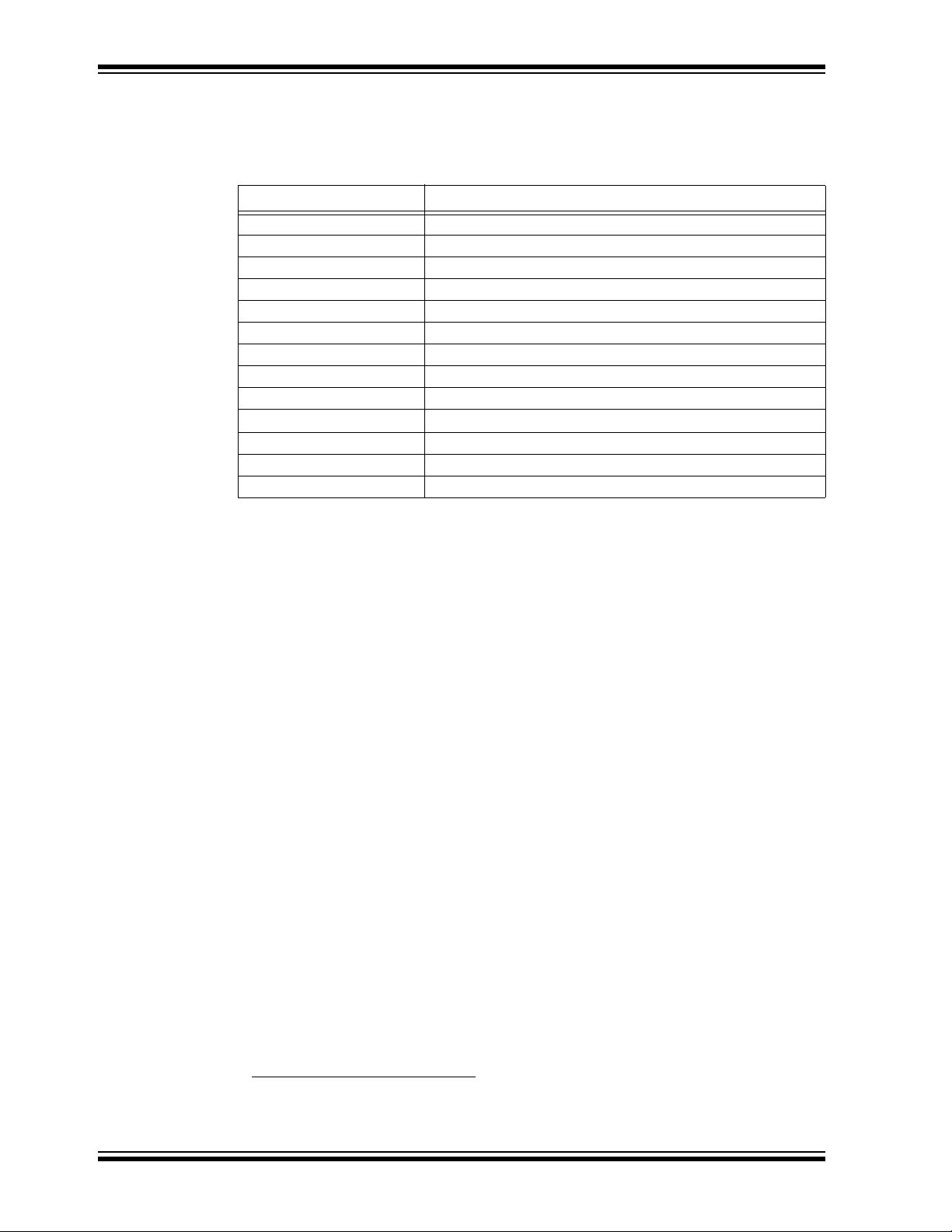
MPLAB® XC8 C Compiler User’s Guide
Table 4-2 lists the compiler applications. The names shown are the names of the executables, which can be found in the bin directory under the compiler’s installation
directory.
TABLE 4-2: COMPILER APPLICATION NAMES
Name Description
xc8 (calls PICC or PICC18) Command line driver; the interface to the compiler
CLIST Text file formatter
CPP The C preprocessor
P1 C code parser
CGPIC or CGPIC18 Code generator (based on the target device)
ASPIC or ASPIC18 Assembler (based on the target device)
HLINK Linker
OBJTOHEX Conversion utility to create HEX files
CROMWELL Debug file converter
HEXMATE
LIBR Librarian
DUMP Object file viewer
CREF Cross reference utility
HEX file utility
For example, C source files (.c files) are first passed to the C preprocessor, CPP. The
output of this application are .pre files. These files are then passed to the parser application, P1, which produces a p-code file output with extension .p1. The applications
are executed in the order specified and temporary files are used to pass the output of
one application to the next.
The compiler can accept more than just C source files. Table 4-1 lists all the possible
input file types, and these files can be seen in this diagram, on the top and bottom,
being passed to different compilation applications. They are processed by these
applications and then the application output joins the normal flow indicated in the
diagram.
For example, assembly source files are passed straight to the assembler application
and are not processed at all by the code generator. The output of the assembler (an
object file with .obj extension) is passed to the linker in the usual way. You can see
that any p-code files (.p1 extension) or p-code libraries (.lpp extension) that are
supplied on the command line are initially passed to the code generator.
Other examples of input files include object files (.obj extension) and object libraries
(.lib extension), both of which are passed initially to the linker, and even HEX files
(.hex extension), which are passed to one of the utility applications, called HEXMATE,
which is run right at the end of the compilation sequence.
Some of the temporary files shown in this diagram are actually preserved and can be
inspected after compilation has concluded. There are also driver options to request that
the compilation sequence stop after a particular application and the output of that
application becomes the final output.
1
1. Assembly file will be preprocessed before being passed to the assembler if the
-P option is selected.
DS52053B-page 76 2012 Microchip Technology Inc.
Page 77

C file
C file
library
files
preprocess
&
parse
p-
code
code
generation
preprocess
&
parse
p-
code
linkassemble
First stage of compilation Second stage of compilation
Intermediate files
XC8 Command-line Driver
FIGURE 4-2: MULTI-FILE COMPILATION
4.3.2 Single-Step Compilation
Figure 4-1 showed us the files that are generated by each application and the order in
which these applications are executed. However this does not indicate how these
applications are executed when there is more than one source file being compiled.
Consider the case when there are two C source files that form a complete project and
that are to be compiled, as is the case shown in Figure 4-2. If these files are called
main.c and io.c, these could be compiled with a single command, such as:
xc8 --chip=16F877A main.c io.c
This command will compile the two source files all the way to the final output, but
internally we can consider this compilation as consisting of two stages.
The first stage involves processing of each source file separately, and generating some
sort of intermediate file for each source file. The second stage involves combining all
these intermediate files and further processing to form the final output. An intermediate
file is a particular temporary file that is produced and marks the mid point between the
first and second stage of compilation.
The intermediate file used by xc8 is the p-code (.p1 extension) file output by the
parser, so there will be one p-code file produced for each C source file. As indicated in
the diagram, CPP and then P1 are executed to form this intermediate file. (For clarity
the CPP and P1 applications have been represented by the same block in the diagram.)
In the second stage, the code generator reads in all the intermediate p-code files and
produces a single assembly file output, which is then passed to the subsequent
applications that produce the final output.
The desirable attribute of this method of compilation is that the code generator, which
is the main application that transforms from the C to the assembly domain, sees the
entire project source code via the intermediate files.
Traditional compilers have always used intermediate files that are object files output by
the assembler. These intermediate object files are then combined by the linker and further processed to form the final output. This method of compilation is shown in
Figure 4-3 and shows that the code generator is executed once for each source file.
Thus the code generator can only analyze that part of the project that is contained in
the source fi le c ur r ent l y b ei n g c om p il ed. T he MP LA B X C 16 a nd X C 32 co m pi le rs w or k
in this fashion.
Using object files as the intermediate file format with MPLAB XC8 C Compiler will
defeat many features the compiler uses to optimize code. Always use p-code files as
the intermediate file format if you are using a make system to build projects.
2012 Microchip Technology Inc. DS52053B-page 77
Page 78

MPLAB® XC8 C Compiler User’s Guide
C file
C file
library
files
preprocess
&
parse
.obj
files
preprocess
&
parse
.obj
files
link
assemble
First stage of compilation
Second stage
of compilation
Intermediate files
code
generation
code
generation
assemble
FIGURE 4-3: THE TRADITIONAL COMPILATION SEQUENCE
When compiling files of mixed types, this can still be achieved with just one invocation
of the compiler driver. As discussed in Section 4.3 “The Compilation Sequence”, the
driver will pass each input file to the appropriate compiler application.
For example, the files, main.c, io.c, mdef.as and c_sb.lpp are to be compiled.
To perform this in a single step, the following command line could be used.
xc8 --chip=16F877A main.c io.c mdef.as c_sb.lpp
As shown in Figure 4-1 and Figure 4-2, the two C files (main.c and io.c) will be compiled to intermediate p-code files; these, along with the p-code library file (c_sb.lpp)
will be passed to the code generator. The output of the code generator, as well as the
assembly source file (mdef.as), will be passed to the assembler.
The driver will recompile all source files, regardless of whether they have changed
since the last build. IDEs (such as MPLAB
to achieve incremental builds. See also Section 4.3.3 “Multi-Step Compilation”.
Unless otherwise specified, a HEX file and Microchip COFF file are produced as the
final output. All intermediate files remain after compilation has completed, but most
other temporary files are deleted, unless you use the --NODEL option (see
Section 4.8.40 “--NODEL: Do Not Remove Temporary Files”) which preserves all
generated files except the run-time start-up file. Note that some generated files may be
in a different directory to your project source files. See Section 4.8.43 “--OUTDIR:
Specify a Directory For Output Files” and Section 4.8.41 “--OBJDI R: Specify a
Directory For Intermediate Files” which can both control the destination for some
output files.
®
IDE) and make utili tie s mu st be e mpl oyed
DS52053B-page 78 2012 Microchip Technology Inc.
Page 79

XC8 Command-line Driver
4.3.3 Multi-Step Compilation
Make utilities and IDEs, such as MPLAB IDE, allow for an incremental build of projects
that contain multiple source files. When building a project, they take note of which
source files have changed since the last build and use this information to speed up
compilation.
For example, if compiling two source files, but only one has changed since the last
build, the intermediate file corresponding to the unchanged source file need not be
regenerated.
MPLAB IDE is aware of the different compilation sequence employed by xc8 and takes
care of this for you. From MPLAB IDE you can select an incremental build (Build Project
icon), or fully rebuild a project (Clean and Build Project icon).
If the compiler is being invoked using a make utility, the make file will need to be configured to recognized the different intermediate file format and the options used to generate the intermediate files. Make utilities typically call the compiler multiple times: once
for each source file to generate an intermediate file, and once to perform the second
stage compilation.
You may also wish to generate intermediate files to construct your own library files.
However, xc8 is capable of constructing libraries in a single step, so this is typically not
necessary. See Section 4.8.44 “--OUTPUT= type: Specify Output File Type” for
more information on library creation.
The option --PASS1 (Section 4.8.45 “--PASS1: Compile to P-code”) is used to tell
the compiler that compilation should stop after the parser has executed. This will leave
the p-code intermediate file behind on successful completion.
For example, the files main.c and io.c are to be compiled using a make utility. The
command lines that the make utility should use to compile these files might be
something like:
xc8 --chip=16F877A --pass1 main.c
xc8 --chip=16F877A --pass1 io.c
xc8 --chip=16F877A main.p1 io.p1
If is important to note that the code generator needs to compile all p-code or p-code
library files associated with the project in the one step. When using the --PASS1 option
the code generator is not being invoked, so the above command lines do not violate
this requi rement.
Using object files as the intermediate file format with MPLAB XC8 C Compiler will
defeat many features the compiler uses to optimize code. Always use p-code files as
the intermediate file format if you are using a make system to build projects.
2012 Microchip Technology Inc. DS52053B-page 79
Page 80

MPLAB® XC8 C Compiler User’s Guide
C file
C file
library
files
preprocess
&
parse
p-
code
code
generation
assemble
preprocess
&
parse
p-
code
ASM
file
OBJ
file
link
assemble
driver
4.3.4 Compilation of Assembly Source
Since the code generator performs many tasks that were traditionally performed by the
linker, there could be complications when assembly source is present in a project.
Assembly files are traditionally processed after C code, but it is necessary to have this
performed first so that specific information contained in the assembly code can be
conveyed to the code generator.
The specific information passed to the code generator is discussed in more detail in
Section 5.12.3 “Interaction Between Assembly and C Code”.
When assembly source is present, the order of compilation is as shown in Figure 4-4.
FIGURE 4-4: COMPILATION SEQUENCE WITH ASSEMBLY FILES
Any assembly source files are first assembled to form object files. These files, along
with any other objects files that are part of the project, are then scanned by the command-line driver and information is then passed to the code generator when it
subsequently builds the C files, as has been described earlier.
4.3.4.1 INTERMEDIATE FILES AND ASSEMBLY SOURCE The intermediate file format associated with assembly source files is the same as that
used in traditional compilers; i.e., an object file (.obj extension). Assembly files are
never passed to the code generator and so the code generator technology does not
alter the way these files are compiled.
The -C option (see Section 4.8.1 “-C: Compile to Object File”) is used to generate
object files and halt compilation after the assembly step.
4.3.5 Printf Check
An extra execution of the code generator is performed prior to the actual code generation phase. This pass is part of the process by which the printf library function is
customized, see Section 5.11.1 “The printf Routine” for more details.
This pass is only associated with scanning the C source code for printf placeholder
usage and you will see the code generator being executed if you select the verbose
option when you build, see Section 4.8.15 “-V: Verbose Compile”.
DS52053B-page 80 2012 Microchip Technology Inc.
Page 81

4.4 RUNTIME FILES
In addition to the C and assembly source files specified on the command line, there are
also compiler-generated source files and pre-compiled library files which might be
compiled into the project by the driver. These files contain:
• C Standard library routines
• Implicitly called arithmetic routines
• User-defined library routines
• The runtime startup code
• The powerup routine
• The printf routine.
Strictly speaking, the power-up routine is neither a compiler-generated source, nor a
library routine. It is fully defined by the user, however as it is very closely associated
with the runtime startup module, it is discussed with the other runtime files in the
following sections.
4.4.1 Library Files
The names of the C standard library files appropriate for the selected target device, and
other driver options, are determined by the driver and passed to the code generator and
linker. You do not need to manually include library files into your project. P-code libraries (.lpp libraries) are used by the code generator, and object code libraries (.lib
files) are used by the linker. Most library routines are derived from p-code libraries.
By default, xc8 will search the lib directory under the compiler installation directory
for library files that are required during compilation.
XC8 Command-line Driver
4.4.1.1 STANDARD LIBRARIES
The C standard libraries contain a standardized collection of functions, such as string,
math and input/output routines. The range of these functions are described in
Appendix A. “Library Functions”. Although it is considered a library function, the
printf function’s code is not found in these library files. C source code for this function is generated from a special C template file that is customized after analysis of the
user’s C code. See Section “PRINTF, VPRINTF” for more information on using the
printf library function and Section 5.11.1 “The printf Routine” for information on
how the printf function is customized when you build a project.
The libraries also contain C routines that are implicitly called by the output code of the
code generator. These are routines that perform tasks such as floating-point operations, integer division and type conversions, and that may not directly correspond to a
C function call in the source code.
The library name format is family-type-options.lpp, where the following apply.
• family can either be pic18 for PIC18 devices, or pic for all other 8-bit PIC
devices
• type indicates the sort of library functionality provided and may be stdlib for
the standard library functions, or trace, etc.
• options indicate hyphen-separated names to indicate variants of the library to
accommodate different compiler options or modes, e.g., htc for HI-TECH C compatibility, d32 for 32-bit doubles, etc.
For example, the standard library for baseline and midrange devices using 24-bit dou-
ble types is pic-stdlib-d24.lpp.
All the librar ies are pres ent in th e lib directory of the compiler installation. Search this
directory for the full list of all libraries supplied.
2012 Microchip Technology Inc. DS52053B-page 81
Page 82

MPLAB® XC8 C Compiler User’s Guide
4.4.1.2 USER-DEFINED LIBRARIES User-defined libraries may be created and linked in with programs as required. Library
files are more easy to manage and may result in faster compilation times, but must be
compatible with the target device and options for a particular project. Several versions
of a library may need to be created to allow it to be used for different projects.
Libraries can be created manually using the compiler and the librarian, LIBR. See
Section 8.2 “Librarian” for more information on the librarian and creating library files
using this application. Alternatively, library files can be created directly from the
compiler by specifying a library output using the --OUTPUT option, see
Section 4.8.44 “--OUTPUT= type: Specify Output File Type”.
User-created libraries that should be searched when building a project can be listed on
the command line along with the source files.
As with Standard C library functions, any functions contained in user-defined libraries
should have a declaration added to a header file. It is common practice to create one
or more header files that are packaged with the library file. These header files can then
be included into source code when required.
Library files specified on the command line are scanned first for unresolved symbols,
so these files may redefine anything that is defined in the C standard libraries. See also
Section 5.15.4 “Replacing Library Modules”.
4.4.2 Startup and Initialization
A C program requires certain objects to be initialized and the device to be in a particular
state before it can begin execution of its function main. It is the job of the runtime
startup code to perform th ese t asks. Section 5.10.1 “Runtime Startup Code” de tail s
specifically what actions are taken by this code and how it interacts with programs you
write.
Rather than the traditional method of linking in a generic, precompiled routine, the
MPLAB XC8 C Compiler determines what runtime startup code is required from the
user’s program and then generates this code each time you build.
Both the driver and code generator are involved in generating the runtime startup code.
The driver creates the code which handles device setup and this code is placed into a
separate assembly startup module. The code generator produces code which initializes the C environment, such as clearing uninitialized C variables and copying
initialized C variables. This code is output along with the rest of the C program.
The runtime startup code is regenerated every time you build a project. The file created
by the driver may be deleted after compilation, and this operation can be controlled with
the keep suboption to the --RUNTIME option. The default operation of the driver is to
keep the startup module; however, if using MPLAB IDE to build, file will be deleted
unless you indicate otherwise in the Project Properties dialog, see.
If the startup module is kept, it will be called startup.as and will be located in the
current working directory. If you are using an IDE to perform the compilation the
destination directory may be dictated by the IDE itself. MPLAB X IDE store this file in
the dist/default/production directory in your project directory.
DS52053B-page 82 2012 Microchip Technology Inc.
Page 83

XC8 Command-line Driver
Generation of the runtime startup code is an automatic process which does not require
any user interaction; however, some aspects of the runtime code can be controlled, if
required, using the --RUNTIME option. Section 4.8.50 “--RUNTIME: Specify Run-
time Environment” describes the use of this option. See Section 5.10.1 “Runtime
Startup Code” which describes the functional aspects of the code contained in this
module and its effect on program operation.
The runtime startup code is executed before main, but If you require any special initial-
ization to be performed immediately after reset, you should use power-up feature
described later in Section 5.10.2 “The Powerup Routine”.
2012 Microchip Technology Inc. DS52053B-page 83
Page 84

MPLAB® XC8 C Compiler User’s Guide
4.5 COMPILER OUTPUT
There are many files created by the compiler during the compilation. A large number of
these are intermediate files and some are deleted after compilation is complete, but
many remain and are used for programming the device, or for debugging purposes.
4.5.1 Output Files
The names of many output files use the same base name as the source file from which
they were derived. For example, the source file input.c will create a p-code file called
input.p1.
Some of the output files contain project-wide information and are not directly associated with any one particular input file, e.g., the map file. If the names of these output
files are not specified by a compiler option, their base name is derived from the first C
source file listed on the command line. If there are no files of this type specified, the
name is based on the first input file (regardless of type) on the command line.
If you are using an IDE, such as MPLAB X IDE, to specify options to the compiler, there
is typically a project file that is created for each application. The name of this project is
used as the base name for project-wide output files, unless otherwise specified by the
user. However check the manual for the IDE you are using for more details.
Note: Throughout this manual, the term project name will refer to either the name
of the project created in the IDE, or the base name (file name without
extension) of the first C source file specified on the command line.
The compiler is able to directly produce a number of the output file formats which are
used by the 8-bit PIC development tools.
The default behavior of xc8 is to produce a Microchip format COFF and Intel HEX output. Unless changed by a driver option, the base names of these files will be the project
name. The default output file types can be controlled by compiler options, e.g., the
--OUTPUT option. The extensions used by these files are fixed and are listed together
with this option’s description in Section 4.8.44 “--OUTPUT= type: Specify Output
File Type”.
The COFF file is used by debuggers to obtain debugging information about the project.
Table 4-14 shows all output format options available with xc8 using the --OUTPUT
option. The File Type column lists the filename extension which will be used for the
output file.
4.5.1.1 SYMBOL FILES xc8 creates two symbol files which are used to generate the debug output files, such
as COFF and ELF files. These are the SYM files (.sym extension) produced by the
linker, and the SDB file (.sdb extension) produced by the code generator.
The SDB file contains type information, and the SYM file contains address information.These two files, in addition to the HEX file, are combined by the CROMWELL application (see Section 8.5 “CROMWELL”) to produce the output debug files, such as the
COFF file.
DS52053B-page 84 2012 Microchip Technology Inc.
Page 85

XC8 Command-line Driver
4.5.2 Diagnostic Files
Two valuable files produced by the compiler are the assembly list file, produced by the
assembler, and the map file, produced by the linker.
The compiler options --ASMLIST (Section 4.8.16 “--ADDRQUAL: Set Compiler
Response to Memory Qualifiers”) generates a list file, and the -M option
(Section 4.8.8 “-M: Generate Map File”) specifies generation of a map file.
The assembly list file contains the mapping between the original source code and the
generated assembly code. It is useful for information such as how C source was
encoded, or how assembly source may have been optimized. It is essential when confirming if compiler-produced code that accesses objects is atomic, and shows the
psects in which all objects and code are placed. For an introductory guide to psects,
see Section 5.15.1 “Program Sections”. And, see Section 6.5 “Assembly-Level
Optimizations” for more information on the contents of this file.
There is one list file produced for the entire C program, including C library files, and
which will be assigned the project name and extension .lst. One additional list file is
produced for each assembly source file compiled in the project.
The map file shows in formatio n relati ng to wh ere obje cts were positio ned in me mory. It
is useful for confirming if user-defined linker options were correctly processed, and for
determining the exact placement of objects and functions. It also shows all the unused
memory areas in a device and memory fragmentation. See Section 7.4 “Map Files”
for complete information on the contents of this file.
There is one map file produced when you build a project, assuming the linker was executed and ran to completion. The file will be assigned the project name and .map
extension.
2012 Microchip Technology Inc. DS52053B-page 85
Page 86

MPLAB® XC8 C Compiler User’s Guide
4.6 COMPILER MESSAGES
All compiler applications, including the command-line driver, xc8, use textual messages to report feedback during the compilation process. A centralized messaging system is used to produce the messages, which allows consistency during all stages of the
compilation process. The messaging system is described in this section and a complete list of all warning and error messages can be found in Appendix B. “Error and
Warning Messages”.
4.6.1 Messaging Overview
A message is referenced by a unique number which is passed to the messaging system by the compiler application that needs to convey the information. The message
string corresponding to this number is obtained from Message Description Files (MDF),
which are stored in the dat directory in the compiler’s installation directory.
When a message is requested by a compiler application, its number is looked up in the
MDF that corresponds to the currently selected language. The language of messages
can be altered as discussed in Section 4.6.2 “Message Language”.
Once found, the alert system can read the message type and the string to be displayed
from the MDF. There are several different message types which are described in
Section 4.6.3 “Message Type” and the type can be overridden by the user, as
described in the same section.
The user is also able to set a threshold for warning message importance, so that only
those which the user considers significant will be displayed. In addition, messages with
a partic ular num ber can be disa bled. A pragma can also be used to dis able a p articul ar
message number within specific lines of code. These methods are explained in
Section 4.6.5.1 “Disabling Messages”.
Provided the message is enabled and it is not a warning message whose level is below
the current warning threshold, the message string will be displayed.
In addition to the actual message string, there are several other pieces of information
that may be displayed, such as the message number, the name of the file for which the
message is applicable, the file’s line number and the application that issued the
message, etc.
If a message is an error, a counter is incremented. After a certain number of errors has
been reached, compilation of the current module will cease. The default number of
errors that will cause this termination can be adjusted by using the --ERRORS option,
see Section 4.8.29 “--ERRORS: Maximum Number of Errors”. This counter is reset
for each internal compiler application, thus specifying a maximum of five errors will
allow up to five errors from the parser, five from the code generator, five from the linker,
five from the driver, etc.
Although the information in the MDF can be modified with any text editor, this is not recommended. Message behavior should only be altered using the options and pragmas
described in the following sections.
DS52053B-page 86 2012 Microchip Technology Inc.
Page 87

XC8 Command-line Driver
4.6.2 Message Language
xc8 supports more than one language for displayed messages. There is one MDF for
each language supported.
Under Windows, the default language can be specified when installing the compiler.
The default language may be changed on the command line using the --LANG option,
see Section 4.8.35 “--LANG: Specify the Language for Messages”. Alternatively , it
may be changed permanently by using the --LANG option together with the --SETUP
option which will store the default language in either the registry, under Windows, or in
the XML configuration file on other systems. On subsequent builds, the default
language used will be that specified.
Table 4-3 shows the MDF applicable for the currently supported languages.
TABLE 4-3: SUPPORTED LANGUAGES
Language MDF name
English en_msgs.txt
German de_msgs.txt
French fr_msgs.txt
If a language other than English is selected, and the message cannot be found in the
appropriate non-English MDF , the alert system tries to find the message in the English
MDF. If an English message string is not present, a message similar to:
error/warning (*) generated, but no description available
where * indicates the message number that was generated that will be printed;
otherwise, the message in the requested language will be displayed.
4.6.3 Message Type
There are four types of messages. These are described below along with the compiler’s behavior when encountering a message of each type.
Advisory Messages conv ey information re garding a situation the compiler has en-
countered or some action the compi ler is about to take. The information is
being displayed “for your interest” and typically requires no action to be
taken. Compilation will continue as normal after such a message is issued.
Warning Messages indicate source code or some oth er situatio n that can be com-
piled, but is unusual and may lead to a runtime failure of the code. The code
or situation that triggered the warning should be investigated; however, compilation of the current module will continue, as will compilation of any
remaining modules.
Error Messages indicate source code that is illegal or that compilation of this code
cannot take place. Compi lation will be attempted for the re maining source
code in the current mod ule, but no ad dition al modu les wi ll be comp iled an d
the compilation process will then conclude.
Fatal Error Messages i ndic ate a situa tion th at ca nnot a llow c ompi lation to proc eed
and which requires the compilation process to stop immediately.
2012 Microchip Technology Inc. DS52053B-page 87
Page 88
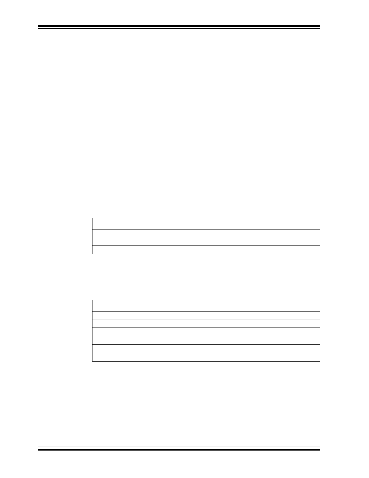
MPLAB® XC8 C Compiler User’s Guide
4.6.4 Message Format
By default, messages are printed in a human-readable format. This format can vary
from one compiler application to another, since each application reports information
about different file formats.
Some applications (for example, the parser) are typically able to pinpoint the area of
interest down to a position on a particular line of C source code, whereas other applications, such as the linker, can at best only indicate a module name and record number,
which is less directly associated with any particular line of code. Some messages relate
to issues in driver options which are in no way associated with any source code.
There are several ways of changing the format in which message are displayed, which
are discussed below.
The driver option -E (with or without a filename) alters the format of all displayed messages. See Section 4.8.3 “-E: Redirect Compiler Errors to a File”. Using this option
produces messages that are better suited to machine parsing, and are less
user-friendly. Ty pically each message is displayed on a single line. The general form of
messages produced when using the -E option is:
filename line: (message number) message string (type)
The -E option also has another effect. When used, the driver first checks to see if special environment variables have been set. If so, the format dictated by these variables
are used as a template for all messages produced by all compiler applications. The
names of these environment variables are given in Table 4-4.
TABLE 4-4: MESSAGING ENVIRONMENT VARIABLES
Variable Effect
HTC_MSG_FORMAT All advisory messages
HTC_WARN_FORMAT All warning messages
HTC_ERR_FORMAT All error and fatal error messages
The value of these environment variables are strings that are used as templates for the
message format. Printf-like placeholders can be placed within the string to allow the
message format to be customized. The placeholders and what they represent are
indicated in Table 4-5.
TABLE 4-5: MESSAGING PLACEHOLDERS
Placeholder Replacement
%a Application name
%c Column number
%f Filename
%l Line number
%n Message number
%s Message string (from MDF)
If these options are used in a DOS batch file, two percent characters will need to be
used to specify the placeholders, as DOS interprets a single percent character as an
argument and will not pass this on to the compiler. For example:
SET HTC_ERR_FORMAT="file %%f: line %%l"
Environment variables, in turn, may be overridden by the driver options: --MSGFORMAT, --WARNFORMAT and --ERRFORMAT, see Section 4.8.28 “--ERRFORMAT:
Define Format for Compiler Messages”. These options take a string as their argument. The option strings are formatted, and can use the same placeholders, as their
variable counte rpar ts.
DS52053B-page 88 2012 Microchip Technology Inc.
Page 89

XC8 Command-line Driver
For example, a project is compiled, but, as shown, produces a warning from the parser
and an error from the linker (numbered 362 and 492, respectively).
main.c: main()
17: ip = &b;
^ (362) redundant "&" applied to array (warning)
(492) attempt to position absolute psect "text" is illegal
Notice that the parser message format identifies the particular line and position of the
offending source code.
If the -E option is now used and the compiler issues the same messages, the compiler
will output:
main.c: 12: (362) redundant "&" applied to array (warning)
(492) attempt to position absolute psect "text" is illegal (error)
The user now uses the --WARNFORMAT in the following fashion:
--WARNFORMAT="%a %n %l %f %s"
When recompiled, the following output will be displayed:
parser 362 12 main.c redundant "&" applied to array
(492) attempt to position absolute psect "text" is illegal (error)
Notice that the format of the warning was changed, but that of the error message was
not. The warning format now follows the specification of the environment variable. The
application name (parser) was substituted for the %a placeholder, the message
number (362) substituted the %n placeholder, etc.
2012 Microchip Technology Inc. DS52053B-page 89
Page 90

MPLAB® XC8 C Compiler User’s Guide
4.6.5 Changing Message Behavior
Both the attributes of individual messages and general settings for the messaging system can be modified during compilation. There are both driver options and C pragmas
that can be used to achieve this.
4.6.5.1 DISABLING MESSAGES Each warning message has a default number indicating a level of importance. This
number is specified in the MDF and ranges from -9 to 9. The higher the number, the
more important the warning.
Warning messages can be disabled by adjusting the warning level threshold using the
--WARN driver option, see Section 4.8.59 “--WARN: Set Warning Level”. Any warn-
ings whose level is below that of the current threshold are not displayed.
The default threshold is 0 which implies that only warnings with a warning level of 0 or
higher will be displayed by default. The information in this option is propagated to all
compiler applications, so its effect will be observed during all stages of the compilation
process.
Warnings may also be disabled by using the --MSGDISABLE option, see
Section 4.8.38 “--MSGDISABLE: Disable Warning Messages”. This option takes a
comma-separated list of message numbers. Those warnings listed are disabled and
will never be issued, regardless of the current warning level threshold.
Some warning messages can also be disabled by using the warning pragm a. Th is
pragma will only affect warnings that are produced by either the parser or the code generator; i.e., errors directly associated with C code. See Section 5.14.4.11 “The
#pragma warning Directive” for more information on this pragma.
Error messages can also be disabled; however, a more verbose form of the command
is required to confirm the action. To specify an error message number in the --MSG-
DISABLE command, the number must be followed by :off to ensure that it is disabled.
For example: --MSGDISABLE=195:off will disable error number 195.
Note: Disabling error or warning messages in no way fixes the condition which
triggered the message. Always use extreme caution when exercising these
options.
4.6.5.2 CHANGING MESSAGE TYPES It is also possible to change the type of some messages. This can only be done for
messages generated by the parser or code generator. See Section 5.14.4.11 “The
#pragma warning Directive” for more information on this pragma.
DS52053B-page 90 2012 Microchip Technology Inc.
Page 91

4.7 XC8 DRIVER OPTIONS
This section looks at the general form of xc8 command-line options and what action
the compiler will perform if no option is specified for a certain feature.
4.7.0.1 GENERAL OPTION FORMATS
All single letter options are identified by a leading dash character , “-”, for exam ple: -C.
Some single letter options specify an additional data field which follows the option
name immediately and without any whitespace, for example: -Ddebug. In this manual,
options are written in upper case and suboptions are in lower case.
Multi-letter, or word, options have two leading dash characters, for example:
--ASMLIST. (Becau se of the double dash, the driver can determine that the option
--DOUBLE, for example, is not a -D option followed by the argument OUBLE.)
Some of these word options use suboptions which typically appear as a comma-sepa-
rated list follo wing an equal character, =, for example: --OUTPUT=hex,cof. The exact
format of the options varies and are described in detail in the following sections.
Some commonly used suboptions include default, which represent the default specification that would be used if this option was absent altogether; all, which indicates
that all the available suboptions should be enabled as if they had each been listed; and
none, which indicates that all suboptions should be disabled. For example:
--OPT=none
will turn off all optimizers.
Some suboptions may be prefixed with a plus character, +, to indicate that they are in
addition to the other suboptions present, or a minus character “-”, to indicate that they
should be excluded. For example:
--OPT=default,-asm
indicates that the default optimization be used, but that the assembler optimizer should
be disabled. If the first character after the equal sign is + or -, then the default keyword
is implied. For example:
--OPT=-asm
is the same as the previous example.
See the –-HELP option, Section 4.8.33 “--HELP: Display Help”, for more information
about options and suboptions.
XC8 Command-line Driver
4.7.1 Default Options
If you run the compiler driver from the command line and do not specify the option for
a feature, it will default to a certain state. Y ou can also specify the default suboption
to double-dash options which will also invoke the default behavior. You can check what
the default behavior is by using the --HELP=option on the command line, see
4.8.33 “--HELP: Display Help”.
If you are compiling from within the MPLAB X IDE, it will, by default, issue explicit
options to the compiler (unless changed in the Project Properties dialog), and these
options may be different to those that are the default on the command line. For example, unless you specify the --ASMLIST option on the command line, the default operation of the compiler is to not produce an assembly list file. However, if you are
compiling from within the MPLAB X IDE, the default operation – in fact this cannot be
disabled – is to always produce an assembly list file.
If you are compiling the same project from the command line and from the MPLAB X
IDE, always check that all options are explicitly specified.
2012 Microchip Technology Inc. DS52053B-page 91
Page 92

MPLAB® XC8 C Compiler User’s Guide
4.8 OPTION DESCRIPTIONS
Most aspects of the compilation can be controlled using the command-line driver, xc8.
The driver will configure and execute all required applications, such as the code
generator, assembler and linker.
xc8 recognizes the compiler options which are tabled below and are explained in detail
in the sections following. The case of the options is not important, however command
shells in most operating systems are case sensitive when it comes to names of files.
TABLE 4-6: DRIVER OPTIONS
Option Meaning
-C Compile to object file and stop
-Dmacro Define preprocessor macro symbol
-Efilename Redirect compile errors
-G[filename] Generate symbolic debug information
-Ipath Specify include path
-Largument Set linker option
-M[filename] Generate map file
-Nnumber Specify identifier length
-Ofile Specify output filename and type
-P Preprocess assembly source
-Q Quiet mode
-S Compile to assembly file and stop
-Umacro Undefine preprocessor macro symbol
-V Verbose mode
--ADDRQUAL=qualifier Specify address space qualifier handling
--ASMLIST Generate assembly list file
--CCI Enforce and expect CCI rules
--CHAR=type Default character type (defunct)
--CHECKSUM=specification C al cu lat e a check s um and store the res ult in program
memory
--CHIP=device Select target device
--CHIPINFO Print device information
--CODEOFFSET=value Specify ROM offset address
--DEBUGGER=type Set debugger environment
--DOUBLE=size Size of double type
--ECHO Echo command line
--EMI=mode Select external memory interface operating mode
--ERRATA=type Specify errata workarounds
--ERRFORMAT=format Set error format
--ERRORS=number Set maximum number of errors
--FILL=specification Specify a ROM-fill value for unused memory
--FLOAT=size Size of float type
--GETOPTION=argument Get advanced options
--HELP=option Help
--HTML=file Generate HTML debug files
--LANG=language Specify language
--MEMMAP=mapfile Display memory map
--MODE=mode Choose operating mode
DS52053B-page 92 2012 Microchip Technology Inc.
Page 93

XC8 Command-line Driver
TABLE 4-6: DRIVER OPTIONS (CONTINUED)
Option Meaning
--MSGDISABLE=list Disable warning messages
--MSGFORMAT=specification Set advisory message format
--NODEL Do not remove temporary files
--NOEXEC Do not execute compiler applicat ion s
--OBJDIR=path Set object files directory
--OPT=optimizations Control optimization
--OUTDIR=path Set output directory
--OUTPUT=path Set output formats
--PASS1 Produce intermediate p-code file and stop
--PRE Produce preprocessed source files and stop
--PROTO Generate function prototypes
--RAM=ranges Adjust RAM ranges
--ROM=ranges Adjust ROM ranges
--RUNTIME=options Specify runtime options
--SCANDEP Scan for dependencies
--SERIAL=specification Insert a hexadecimal code or serial number
--SETOPTION=argument Set advanced options
--SETUP=specification Set up the co mpi ler
--SHROUD Shroud (obfuscate) generated p-code files
--STRICT Use strict ANS I keywords
--SUMMARY=type Summary options
--TIME Report compilation times
--VER Show version information
--WARN=number Set warning threshold level
--WARNFORMAT=specification Set warning format
4.8.1 -C: Compile to Object File
The -C option is used to halt compilation after executing the assembler, leaving a relocatable object file as the output. It is frequently used when compiling assembly source
files using a make utility. It cannot be used unless all C source files are present on the
command line. Use --PASS1 to generate intermediate files from C source, see
Section 4.8.45 “--PASS1: Compile to P-code”.
See Section 4.3.3 “Multi-Step Compilation” for more information on generating and
using intermediate files.
2012 Microchip Technology Inc. DS52053B-page 93
Page 94

MPLAB® XC8 C Compiler User’s Guide
4.8.2 -D: Define Macro
The -D option is used to define a preprocessor macro on the command line, exactly as
if it had been defined using a #define directive in the source code. This option may
take one of two forms, -Dmacro which is equivalent to:
#define macro 1
placed at the top of each module compiled using this option, or -Dmacro= text which
is equivalent to:
#define macro text
where text is the textual substitution required. Thus, the command:
--CHIP=16F877AA -Ddebug -Dbuffers=10 test.c
xc8
will compile test.c with macros defined exactly as if the C source code had included
the directives:
#define debug 1
#define buffers 10
Defining macros as C string literals requires bypassing any interpretation issues in the
operating system that is being used. T o pass the C string, "hello world", (including
the quote characters) in the Windows environment, use: "-DMY_STRING=\\\"hello
world\\\"" (you must include the quote characters around the entire option as there
is a space character in the macro definition). Under Linux or Mac OS X, use:
-DMY_STRING=\"hello\ world\".
See Section 4.9 “MPLAB IDE V8 Universal Toolsuite Equivalents” or
Section 4.10 “MPLAB X Universal Toolsuite Equivalents” for use of this option in
MPLAB IDE.
4.8.3 -E: Redirect Compiler Errors to a File
This option has two purposes. The first is to change the format of displayed messages.
The second is to optionally allow messages to be directed to a file as some editors do
not allow the standard command line redirection facilities to be used when invoking the
compiler.
The general form of messages produced with the -E option in force is:
filename line_number: (message number) message string (type)
If a filename is specified immediately after -E, it is treated as the name of a file to which
all messages (errors, warnings, etc.) will be printed. For example, to compile x.c and
redirect all errors to x.err, use the command:
--CHIP=16F877AA -Ex.err x.c
xc8
The -E option also allows errors to be appended to an existing file by specifying an
addition character, +, at the start of the error filename, for example:
xc8
--CHIP=16F877AA -E+x.err y.c
If you wish to compile several files and combine all of the errors generated into a single
text file, use the -E option to create the file then use -E+ when compiling all t h e o t he r
source files. For example, to compile a number of files with all errors combined into a
file called project.err, you could use the - E option as follows:
xc8
--CHIP=16F877AA -Eproject.err -O --PASS1 main.c
xc8 --CHIP=16F877AA -E+project.err -O --PASS1 part1.c
xc8 --CHIP=16F877AA -E+project.err -C asmcode.as
Section 4.6 “Compiler Messages” has more information regarding this option as well
as an overview of the messaging system and other related driver options.
DS52053B-page 94 2012 Microchip Technology Inc.
Page 95

XC8 Command-line Driver
4.8.4 -G: Generate Source-Level Symbol File
The -G option allows specification of the filename used for the source-lev el symb ol file
(.sym extension) for use with supported debuggers and simulators such as MPLAB
IDE. See also Section 4.5 “Compiler Output”.
If no filename is given, the symbol file will have the project name (see
Section 4.2 “Invoking the Compiler”), and an extension of .sym. For example, the
option -Gtest.sym generates a symbol file called test.sym. Symbol files generated
using the -G option include source-level information for use with source-level debuggers.
4.8.5 -I: Include Search Path
Use -I to specify an additional directory to search for header files which have been
included us in g t h e #include directive. The directory can either be an absolute or relative path. The -I option can be used more than once if multiple directories are to be
searched.
The compiler’s include directory containing all standard header files is always
searched, even if no -I option is present. If header filenames are specified using quote
characters rather than angle brackets, as in #include "lcd.h", then the current
working directory is searched in addition to the compiler’s include directory. Note that
if compiling within MPLAB IDE, the search path is relative to the output directory, not
the project directory.
These default search paths are searched after any user-specified directories have
been searched. For example:
xc8
--CHIP=16F877AA -C -Ic:\include -Id:\myapp\include test.c
will search t he direc tories c:\include and d:\myapp\include for any header files
included into the source code, then search the default include directory.
This option has no effect for files that are included into assembly source using the
assembly INCLUDE directive. See Section 6.4.10.4 “INCLUDE”.
See Section 4.9 “MPLAB IDE V8 Universal Toolsuite Equivalents” or
Section 4.10 “MPLAB X Universal Toolsuite Equivalents” for use of this option in
MPLAB IDE.
4.8.6 -L: Scan Library
The -L option is used to specify additional libraries which are to be scanned by the
linker. Libraries specified using the -L option are scanned before the standard C library,
allowing additional versions of standard library functions to be accessed.
The argument to -L is a library keyword to which the prefix pic; numbers representing
the device range, number of ROM pages and the number of RAM banks; and the suffix
.lib are added.
Thus the option -Ll when compiling for a 16F877A will, for example, scan the library
pic42c-l.lib and the option -Lxx will scan a library called pic42c-xx.lib.
All libraries must be located in the lib directory of the compiler installation directory.
As indicated, the argument to the -L option is not a complete library filename. If you
wish the linker to scan libraries whose names do not follow the above naming convention or whose locations are not in the lib subdirectory, simply include the libraries’
names on the command line along with your source files, or add these to your project.
2012 Microchip Technology Inc. DS52053B-page 95
Page 96

MPLAB® XC8 C Compiler User’s Guide
4.8.7 -L-: Adjust Linker Options Directly
The -L driver option can be used to specify an option which will be passed directly to
the linker. If -L is followed immediately by text starting with a dash character “-”, the
text will be passed directly to the linker without being interpreted by xc8. If the -L
option is not followed immediately by a dash character, it is assumed the option is the
library scan option, Section 4.8.6 “-L: Scan Library”.
For example, if the option -L-N is specified, the -N option will be pass ed on to the link er
without any subsequent interpretation by the driver. The linker will then process this
option, when, and if, it is invoked, and perform the appropriate operation.
Take care with command-line options. The linker cannot interpret command-line driver
options; similarly the driver cannot interpret linker options. In most situations, it is
always the command-line driver, xc8, that is being executed. If you need to add alternate linker settings in the Linker category in the Project Properties dialogue, you must
add driver options (not linker options). These driver options will be used by the driver
to generate the appropriate linker options during the linking process. The -L option is
a means of allowing a linker option to be specified via a driver option.
The -L option is especially useful when linking code which contains non-standard program sections (or psects), as may be the case if the program contains hand-written
assembly code which contains user-defined psects (see 6.4.9.3 “PSECT” and
Section 5.15.1 “Program Sections”), or C code which uses the #pragma psect
directive (see 5.14.4.8 “The #pragma psect Directive”). Without this -L option, it
would be necessary to invoke the linker manually to allow the linker options to be
adjusted.
This option can also be used to replace default linker options. If the string starting from
the first character after the -L up to the first equal character, "=", matches a psect or
class name in the default options, then (the reference to the psect or class name in the
default option, and the remainder of that option, are deleted) that default linker option
is replaced by the option specified by the -L. For example, if a default linker option was:
-preset_vec=00h,intentry,init,end_init
the driver option -L-pinit=100h would result in the following options being passed
to the linker: -pinit=100h -preset_vec=00h. Note the end_init linker option
has been removed entirely. If there are no characters following the first equal character
in the -L option, then no replacement will be made for the default linker options that will
be deleted. For example, the driver option -L-pinit= wil l adju st the defa ult option s
passed to the linker, as above, but the -pinit linker option would be removed entirely.
No warning is generated if such a default linker option cannot be found. The default
option that you are deleting or replacing must contain an equal character.
4.8.8 -M: Generate Map File
The -M option is used to request the generation of a map file. The map file is generated
by the linker and includes detailed information about where objects are located in memory. See Section 7.4 “Map Files” for information regarding the content of these files.
If no filename is specified with the option, then the name of the map file will have the
project name (see Section 4.3 “The Compilation Sequence”), with the extension
.map.
This option is on by default when compiling from within MPLAB X IDE and using the
Universal Toolsuite.
DS52053B-page 96 2012 Microchip Technology Inc.
Page 97

XC8 Command-line Driver
4.8.9 -N: Identifier Length
This option allows the significant C identifier length (used by functions and variables)
to be decreased from the default value of 255. Valid sizes for this option are from 32 to
255. The option has no effect for all other values.
This option also controls the significant length of identifiers used by the preprocessor,
such as macro names. The default length is also 255, and can be adjusted to a
minimum of 31.
If the --STRICT option is used, the default significant identifier length is reduced to 31.
Code which uses a longer identifier length will be less portable.
See Section 4.9 “MPLAB IDE V8 Universal Toolsuite Equivalents” or
Section 4.10 “MPLAB X Universal Toolsuite Equivalents” for use of this option in
MPLAB IDE.
4.8.10 -O: Speci fy Output File
This option allows the basename of the output file(s) to be specified. If no -O option is
given, the base name of output file(s) will be the same as the project name, see
Section 4.3 “The Compilation Sequence”. The files whose names are affected by
this option are those files that are not directly associated with any particular source file,
such as the HEX file, MAP file and SYM file.
The -O option can also change the directory in which the output file is located by including the required path before the filename. This will then also specify the output directory
for any files produced by the linker or subsequently run applications. Any relative paths
specified are with respect to the current working directory.
For example, if the option -Oc:\project\output\first is used, the MAP and
HEX file, etc., will use the base name first, and will be placed in the directory
c:\project\output.
Any extension supplied with the filename will be ignored.
The options that specify MAP file creation (-M, see Section 4.8.8 “-M: Generate Map
File”), and SYM file creation (-G, se e Section 4.8.4 “-G: Generate Source-Level
Symbol File”) override any name or path information provided by -O relevant to the
MAP and SYM file.
To change the directory in which all output and intermediate files are written, use the
--OUTDIR option, see Section Section 4.8.43 “--OUTDIR: Specify a Directory For
Output Files”. Note that if -O specifies a path which is inconsistent with the path
specified in the --OUTDIR option, this will result in an error.
4.8.11 -P: Preprocess Assembly Files
The -P option causes assembler source files to be preprocessed before they are
assembled, thus al low ing the us e of pr epro cess or dir ecti ves , suc h as #include, and
C-style comments with assembler code.
By default, assembler files are not preprocessed.
See Section 4.9 “MPLAB IDE V8 Universal Toolsuite Equivalents” or
Section 4.10 “MPLAB X Universal Toolsuite Equivalents” for use of this option in
MPLAB IDE.
4.8.12 -Q: Quiet Mode
This option places the compiler in a quiet mode which suppresses the Microchip
Technology Incorporated copyright notice from being displayed.
2012 Microchip Technology Inc. DS52053B-page 97
Page 98

MPLAB® XC8 C Compiler User’s Guide
4.8.13 -S: Compile to Assembler Code
The -S option stops compilation after generating an assembly output file. One
assembly file will be generated for all the C source code, including p-code library code.
The command xc8 --CHIP=16F877A -S test.c will produce an assembly file called
test.as, which contains the assembly code generated from test.c. The generated
file is valid assembly code which could be passed to xc8 as a source file, however this
should only be done for exploratory reasons. To take advantage of the benefits of the
compilation technology in the compiler, it must compile and link all the C source code
in a single step. See the --PASS1 option (Section 4.8.45 “--PASS1: Compile to
P-code”) to generate intermediate files if you wish to compile code using a two-step
process or use intermediate files.
This option is useful for checking assembly code output by the compiler. The file produced by this option differs to that produced by the --ASMLIST option (see
Section 4.8.16 “--ADDRQUAL: Set Compiler Response to Memory Qualifiers”) in
that it does not contain op-codes or addresses and it may be used as a source file in
subsequent compilations. The assembly list file is more human readable, but is not a
valid assembly source file.
4.8.14 -U: Undefine a Macro
The -U option, the inverse of the -D option, is used to undefine predefined macros.
This option takes the form -Umacro, where macro is the name of the macro to be
undefined
The option, -Udraft, for example, is equivalent to:
#undef draft
placed at the top of each module compiled using this option.
See Section 4.9 “MPLAB IDE V8 Universal Toolsuite Equivalents” or
Section 4.10 “MPLAB X Universal Toolsuite Equivalents” for use of this option in
MPLAB IDE.
4.8.15 -V: Verbose Compile
The -V option specifies verbose compilation. When used, the compiler will display the
command lines used to invoke each of the compiler applications described in
Section 4.3 “The Compilation Sequence”.
The name of the compiler application being executed will be displayed, plus all the
command-line arguments to this application. This option is useful for confirming options
and files names passed to the compiler applications.
If this option is used twice (-V -V), it will display the full path to each compiler application as well as the full command-line arguments. This would be useful to ensure that
the correct compiler installation is being executed, if there is more than one compiler
installed.
See Section 4.9 “MPLAB IDE V8 Universal Toolsuite Equivalents” or
Section 4.10 “MPLAB X Universal Toolsuite Equivalents” for use of this option in
MPLAB IDE.
DS52053B-page 98 2012 Microchip Technology Inc.
Page 99

XC8 Command-line Driver
4.8.16 --ADDRQUAL: Set Compiler Response to Memory Qualifiers
The --ADDRQUAL option indicates the compiler’s response to non-standard memory
qualifiers in C source code.
By default these qualifiers are ignored; i.e., they are accepted without error, but have
no effect. Using this option allows these qualifiers to be interpreted differently by the
compiler.
The near qualifier is affected by this option. On PIC18 devices, this option also affects
the far qualifier; and for other 8-bit devices, the bankx qualifiers (bank0, bank1,
bank2, etc.) are affected.
The suboptions are detailed in Table 4-7.
TABLE 4-7: COMPILER RESPONSES TO MEMORY QUALIFIERS
Selection Response
require The qualifiers will be honored. If they cannot be met, an error will be issued.
request T he qual ifi ers w ill be h onored, if po ss ibl e. N o e rror wil l be gen erated if they
cannot be followed.
ignore The qualifiers will be ignored and code compiled as if they were not used.
reject If the qualifiers are encountered, an error will be immediately generated.
For example, when using the option --ADDRQUAL=request the compiler will try to
honor any non-standard qualifiers, but silently ignore them if they cannot be met.
See Section 4.9 “MPLAB IDE V8 Universal Toolsuite Equivalents” or
Section 4.10 “MPLAB X Universal Toolsuite Equivalents” for use of this option in
MPLAB IDE.
4.8.17 --ASMLIST: Generate Assembler List Files
The --ASMLIST option tells xc8 to generate assemble r li sti ng fil es for the C and
assembly source modules being compiled. One assembly list file is produced for the
entire C program, including code from the C library functions.
Additionally, one assembly list file is produced for each assembly source file in the
project, including the runtime startup code. For more information, see
Section 4.4.2 “Startup and Initialization”.
Assembly list fi les us e a .lst extension and, due to the additional information placed
in these files, cannot be used as assembly source files.
In the case of listings for C source code, the list file shows both the original C code and
the corresponding assembly code generated by the compiler. See
Section 6.5 “Assembly-Level Optimizations” for full information regarding the
content of these files.
The same information is shown in the list files for assembly source code.
This option is on by default when compiling under MPLAB IDE.
4.8.18 --CCI: Enforce and Expect CCI Conformance
Enabling this option will request the compiler to check all source code and compiler
options for compliance with the Common Compiler Interface (CCI) standard. Code that
complies with this standard is portable across all MPLAB XC compilers. (The document
describing the CCI standard is pending at the time of this user’s guide’s writing.) Code
or options that do not conform to the CCI standard will be flagged by compiler warnings.
2012 Microchip Technology Inc. DS52053B-page 99
Page 100

MPLAB® XC8 C Compiler User’s Guide
4.8.19 --CHECKSUM: Calculate a Checksum
This option will perform a checksum over the address range specified and store the
result at the destination address specified. The general form of this option is as follows.
-CHECKSUM=start-end@destination[,offset=][,width=w][,code=c][,algorith
m=a]
Additional specifications are appended as a comma-separated list to this option. Such
specifications are:
width=n selects the width of the checksum result in bytes. A negative width will store
the result in little-endian byte order. Result widths from one to four bytes are
permitted.
offset=nnnn specifies an initial value or offset to be added to this checksum.
algorithm=n select one of the ch ecksum algor ithms impl emente d in HEXMATE. The
selectable algorithms are described in Table 8-9.
code=nn is a hexadecimal code that will trail each byte in the checksum result. This
can allow each byte of the checksum result to be embedded within an
instruction.
The start, end and destination attributes are, by default, hexadecimal constants.
If an accompanying --FILL option has not been specified, unused locations within the
specified address range will be filled with FFFh for baseline devices, 3FFFh for
mid-range devices, or FFFF for PIC18 devices. This is to remove any unknown values
from the equation and ensure the accuracy of the checksum result.
For example:
--checksum=800-fff@20,width=1,algorithm=8
will calculate a 1 byte checksum from address 0x800 to 0xfff and store this at address
0x20. Fletcher’s algorithm will be used. See Section 8.6.1.5 “-CK”.
The checksum calculations are performed by the HEXMATE application. The information in this driver option is passed to the HEXMA TE application when it is executed.
4.8.20 --CHIP: Define Device
This option must be used to specify the target device, or device, for the compilation.
This is the only compiler option that is mandatory when compiling code.
To see a list of supported devices that can be used with this option, use the --CHIP-
INFO option described in Section 4.8.21 “--CHIPINFO: Display List of Supported
Devices”.
4.8.21 --CHIPINFO: Display List of Support ed Devices
The --CHIPINFO option displays a list of device s the compiler sup ports. The nam es
listed are those chips defined in the chipinfo file and which may be used with the
--CHIP option.
Compiler execution will terminate after this list has been printed.
DS52053B-page 100 2012 Microchip Technology Inc.
 Loading...