

Page 1
MPLAB® Starter Kit for
PIC24H Microcontrollers
User’s Guide
© 2008 Microchip Technology Inc. DS51780A
Page 2
Note the following details of the code protection feature on Microchip devices:
• Microchip products meet the specification contained in their particular Microchip Data Sheet.
• Microchip believes that its family of products is one of the most secure families of its kind on the market today, when used in the
intended manner and under normal conditions.
• There are dishonest and possibly illegal methods used to breach the code protection feature. All of these methods, to our
knowledge, require using the Microchip products in a manner outside the operating specifications contained in Microchip’s Data
Sheets. Most likely, the person doing so is engaged in theft of intellectual property.
• Microchip is willing to work with the customer who is concerned about the integrity of their code.
• Neither Microchip nor any other semiconductor manufacturer can guarantee the security of their code. Code protection does not
mean that we are guaranteeing the product as “unbreakable.”
Code protection is constantly evolving. We at Microchip are committed to continuously improving the code protection features of our
products. Attempts to break Microchip’s code protection feature may be a violation of the Digital Millennium Copyright Act. If such acts
allow unauthorized access to your software or other copyrighted work, you may have a right to sue for relief under that Act.
Information contained in this publication regarding device
applications and t he lik e is provided only for your convenience
and may be su perseded by upda t es . It is y our responsibility to
ensure that your application meets with your specifications.
MICROCHIP MAKES NO REPRESENTATIONS OR
WARRANTIES OF ANY KIND WHETHER EXPRESS OR
IMPLIED, WRITTEN OR ORAL, STATUTORY OR
OTHERWISE, RELATED TO THE INFORMATION,
INCLUDING BUT NOT LIMITED TO ITS CONDITION,
QUALITY, PERFORMANCE, MERCHANTABILITY OR
FITNESS FOR PURPOSE. Microchip disclaims all liability
arising from this information and its use. Use of Microchip
devices in life supp ort and/or safety ap plications is entir ely at
the buyer’s risk, and the buyer agrees to defend, indemnify and
hold harmless M icrochip from any and all dama ges, claims,
suits, or expenses re sulting from such use. No licens es are
conveyed, implicitly or otherwise, under any Microchip
intellectual property rights.
Trademarks
The Microchip name and logo, the Microchip logo, Accuron,
dsPIC, K
EELOQ, KEELOQ logo, MPLAB, PIC, PICmicro,
PICSTART, rfPIC, SmartShunt and UNI/O are registered
trademarks of Microchip Technology Incorporated in the
U.S.A. and other countries.
FilterLab, Linear Active Thermistor, MXDEV, MXLAB,
SEEVAL, SmartSensor and The Embedded Control Solutions
Company are registered trademarks of Microchip Technology
Incorporated in the U.S.A.
Analog-for-the-Digital Age, Application Maestro, CodeGuard,
dsPICDEM, dsPICDEM.net, dsPICworks, dsSPEAK, ECAN,
ECONOMONITOR, FanSense, In-Circuit Serial
Programmin g , IC SP, ICEPIC, Mindi, MiW i , MPASM, MPLAB
Certified logo, MPLIB, MPLINK, mTouch, PICkit, PICDEM,
PICDEM.net, PICtail, PIC
32
logo, PowerCal, PowerInfo,
PowerMate, PowerT ool, REAL ICE, rfLAB, Select Mode, Total
Endurance, WiperLock and ZENA are trademarks of
Microchip Technology I ncorporat ed in the U.S.A. and other
countries.
SQTP is a service mark of Microchip Technology Incorporated
in the U.S.A.
All other trademarks mentioned herein are property of their
respective companies.
© 2008, Microchip Technology Incorporat ed, Printed in the
U.S.A., All Rights Reserved.
Printed on recycled paper.
Microchip received ISO/TS-16949:2002 certification for its worldwide
headquarters, design and wafer fabrication facilities in Chandler and
Tempe, Arizona; Gresham, Oregon and design centers in California
and India. The Company’s quality system processes and procedures
are for its PIC
devices, Serial EEPROMs, microperipherals, nonvolatile memory and
analog products. In addition, Microchip’s quality system for the design
and manufacture of development systems is ISO 9001:2000 certified.
®
MCUs and dsPIC® DSCs, KEELOQ
®
code hopping
DS51780A-page ii © 2008 Microchip Technology Inc.
Page 3

MPLAB® STARTER KIT FOR PIC24H
MICROCONTROLLERS USER’S GUIDE
Table of Contents
Preface ...........................................................................................................................1
Chapter 1. Introduction
1.1 Overview ............. ........................................................................................... 7
1.2 Operational Requirements .............................................................................8
1.3 Board Setu p ............. .......................... .. .. ..................................................... ... 8
Chapter 2. Starter Kit Demo
2.1 Running th e D e mo ...................................... .. .. ........................... .. .. ............. ... 9
2.2 Understanding the Demo ................................................. .......................... ..14
2.3 Other Demo Co d e E x a mp le s ..................................................... .................. 15
Chapter 3. Develop an Application
3.1 Installing the Hardware and Software .............. .. ..........................................17
3.2 Setting Up an Example Application for Debug .............................................18
3.3 Running th e E xa mple Applicat io n ............. ............. .. .. .............. .. .. ............. .. . 19
3.4 Debugging the Example Application ............................................................19
3.5 Programming the Debugged Application ........................ .. ............................22
3.6 Creating Other PIC24H MCU Applications ................................................... 22
3.7 Determining Device Support and Reserved Resources ...............................22
3.8 Troubleshooting ............................................................................................23
3.9 Settings Dia lo g , Info Tab .............................................................................. 23
Chapter 4. Hardware
4.1 Application Functional Overview ..................................................................25
4.2 Debug Functional Overview .........................................................................28
4.3 Board Components ......................................................................................29
Appendix A. Schematics
A.1 Applicati o n S c h e ma tics ....... ......................................................................... 34
A.2 Debug Schematics .......................................................................................37
Index .............................................................................................................................39
Worldwide Sales and Service ....................................................................................40
© 2008 Microchip Technology Inc. DS51780A-page iii
Page 4

MPLAB® Starter Kit for PIC24H Microcontrollers User’s Guide
NOTES:
DS51780A-page iv © 2008 Microchip Technology Inc.
Page 5
MPLAB® STARTER KIT FOR PIC24H
MICROCONTROLLERS USER’S GUIDE
Preface
NOTICE TO CUSTOMERS
All documentation becomes dated, and this manual is no exception. Microchip tools and
documentation are constantly evolving to meet customer needs, so some actual dialogs
and/or tool descriptions may differ from those in this document. Please refer to our web site
(www.microchip.com) to obtain the latest documentation available.
Documents are identified with a “DS” number. This number is located on the bottom of each
page, in front of the p age number. The numbering convention for the DS number is
“DSXXXXXA”, where “XXXXX” is the document number and “A” is the revision level of the
document.
For the most up-to-date information on development tools, see the MPLAB
Select the Help menu, and then Topics to open a list of available online help files.
INTRODUCTION
®
IDE online help.
This chapter contains general information that will be useful to know before you use the
MPLAB
chapter include:
• Document Layout
• Conventions Used in this Guide
• Warranty Registration
• Recommended Reading
• The Microchip Web Site
• Development Systems Customer Change Notification Service
• Customer Support
• Document Revision History
DOCUMENT LAYOUT
This document describes how to use the starter kit as a development and demonstrative tool for PIC24H MCU device’s processing capabilities. The manual layout is as
follows:
• Chapter 1. Introduction – This chapter introduces the starter kit and provides an
overview of its features.
• Chapter 2. Starter Kit Demo – This chapter describes how to use the starter kit
demo software.
• Chapter 3. Develop an Application – This chapter describes how to debug
application software on the starter kit using MPLAB
• Chapter 4. Hardware – This chapter provides a functional overview of the starter
kit and identifies the major hardware components.
• Appendix A. Schematics – This appendix provides detailed schematic diagrams
of the starter kit.
®
Starter Kit for PIC24H Microcontrollers (MCUs). Items discussed in this
®
IDE.
© 2008 Microchip Technology Inc. DS51780A-page 1
Page 6
MPLAB® Starter Kit for PIC24H Microcontrollers User’s Guide
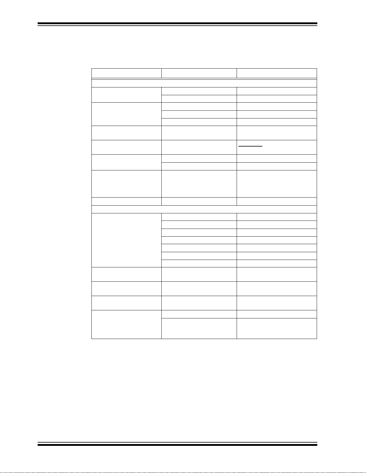
CONVENTIONS USED IN THIS GUIDE
This manual uses the following docum entat io n conven tion s:
DOCUMENTATION CONVENTIONS
Description Represents Examples
Arial font:
Italic chara c ters Referenced books MPLAB
Emphasized text ...is the only compiler...
Initial caps A window the Output window
A dialog the Settings dialog
A menu selection select Enable Programmer
Quotes A field name in a window or
dialog
Underlined, italic text with
right angle bracket
Bold characters A dialog button Click OK
N‘Rnnnn A number in verilog format,
Text in angle brackets < > A key on the keyboard Press <Enter>, <F1>
Courier New font:
Plain Courier New Sample source code #define START
Italic Courier New A variable argument file.o, where file can be
Square brackets [ ] Optional arguments mcc18 [options] file
Curly brackets and pipe
character: { | }
Ellipses... Replaces r epeated text var_name [, var_name...]
A menu path File>Save
A tab Click the Power tab
where N is the tota l number of
digits, R is th e radi x and n is a
digit.
Filenames autoexec.bat
File paths c:\mcc18\h
Keywords _asm, _endasm, static
Command-line options -Opa+, -Opa-
Bit values 0, 1
Constants 0xFF, ‘A’
Choice of mut ually exclus ive
arguments; an OR selection
Represents code supplied by
user
“Save project before build”
4‘b0010, 2‘hF1
any valid filename
[options]
errorlevel {0|1}
void main (void)
{ ...
}
®
IDE User’s Guide
DS51780A-page 2 © 2008 Microchip Technology Inc.
Page 7

WARRANTY REGISTRATION
Please complete the enclosed Warranty Registration Card and mail it promptly.
Sending in the Warranty Registration Card entitles you to receive new product updates.
Interim software releases are available at the Microchip web site.
RECOMMENDED READING
This user’s guide describes how to use the MPLAB Starter Kit for PIC24H MCUs. Other
useful documents are listed below. The following Microchip documents are available
and recommended as supplemental reference resources.
Readme Files
For the latest information on Microchip tools, read the associated Readme files (HTML
files) included with the software.
PIC24H MCU Documentation
For the most up-to-date information on PIC24H MCU devices (data sheets, errata,
family reference manual, etc.), please see the Microchip web site at:
http\\www.microchip.com.
MPLAB
This document helps you use Microchip’s 16-bit C compilers to develop your application. The compilers are the MPLAB C Compiler for dsPIC DSCs and PIC24 MCUs, the
MPLAB C Compiler for dsPIC DSCs (subset of the first), and the MPLAB C Compiler
for PIC24 MCUs (subset of the first). These compilers are GNU-based language tools,
based on source code from the Free Software Foundation (FSF). For more information
about FSF, see www.fsf.org.
MPLAB
User’s Guide (DS51317)
This document helps you use Microchip Technology’s 16-bit language tools based on
GNU technology. The language tools discussed are the MPLAB Assembler for dsPIC
DSCs and PIC24 MCUs, MPLAB Object Linker for dsPIC DSCs and PIC24 MCUs,
MPLAB Archiver/Librarian for dsPIC DSCs and PIC24 MCUs and other 16-bit device
utilities.
MPLAB
This document describes how to use the MPLAB IDE integrated development environment, as well as the MPLAB Project manager, MPLAB Editor and MPLAB SIM
simulator. Use these development tools to help you develop and debug application
code.
®
C Compiler for PIC24 MCUs and dsPIC® DSCs User’s Guide (DS51284)
®
Assembler, Linker and Utilities for PIC24 MCUs and dsPIC® DSCs
®
IDE User’s Guide (DS51519)
Preface
© 2008 Microchip Technology Inc. DS51780A-page 3
Page 8

MPLAB® Starter Kit for PIC24H Microcontrollers User’s Guide
THE MICROCHI P WEB SITE
Microchip provides online support via our web site at www.microchip.com. This web
site is used as a means to make files and information easily available to customers.
Accessible by using your favorite Internet browser, the web site contains the following
information:
• Product Support – Data sheets and errata, application notes and sample
programs, design resources, user’s guides and hardware support documents,
latest software releases and archived software
• General Technical Support – Frequently Asked Questions (FAQs), technical
support requests, online discussion groups, Microchip consultant program
member listin g
• Business of Microchip – Product selector and ordering guides, latest Microchip
press releases, listing of seminars and events, listings of Microchip sales offices,
distributors and factory representatives
DEVELOPMENT SYSTEMS CUSTOMER CHANGE NOTIFICATION SERVICE
Microchip’s customer notification service helps keep customers current on Microchip
products. Subscribers will receive e-mail notification whenever there are changes,
updates, revisions or errata related to a specified product family or development tool of
interest.
To register, access the Microchip web site at www.microchip.com, click on Customer
Change Notification and follow the registration instructions.
The Development Systems product group categories are:
• Compilers – The latest information on Microchip C compilers and other language
tools. These include 16-bit language tools:
- MPLAB C Compiler for dsPIC DSCs and PIC24 MCUs (and subsets)
- MPLAB Assembler for dsPIC DSCs and PIC24 MCUs
- MPLAB Object Linker for dsPIC DSCs and PIC24 MCUs
- MPLAB Archiver/Librarian for dsPIC DSCs and PIC24 MCUs
and 8-bit language tools:
- MPLAB C Compiler for PIC18 MCUs
-MPASM™ Assembler
- MPLINK™ Object Linker
- MPLIB™ Object Librarian
• In-Circuit Emulators – The latest information on Microchip in-circuit emulators.
These include the MPLAB REAL ICE and MPLAB ICE 2000 in-circuit emulators.
• In-Circuit Debuggers – The latest information on Microchip in-circuit debuggers.
These include MPLAB ICD 2, MPLAB ICD 3, and PICkit™ 2.
• MPLAB IDE – The latest information on Microchip MPLAB IDE, the Windows
Integrated Development Environment for development systems tools. This list is
focused on the MPLAB IDE, MPLAB IDE Project Manager, MPLAB Editor and
MPLAB SIM simulator, as well as general editing and debugging features.
• Programmers – The latest information on Microchip programmers. These include
the MPLAB PM3 device programmer and the PICSTART
development programmers.
®
Plus and PICkit 1 and 2
®
DS51780A-page 4 © 2008 Microchip Technology Inc.
Page 9

CUSTOMER SUPPORT
Users of Microchip products can receive assistance through several channels:
• Distributor or Representative
• Local Sales Office
• Field Application Engineer (FAE)
• Technical Support
Customers should contact their distributor, representative or field application engineer
(FAE) for support. Local sales offices are also available to help customers. A listing of
sales offices and locations is included in the back of this document.
Technical support is available through the web site at: http://support.microchip.com
DOCUMENT REVISION HISTORY
Revision A (November 2008)
This is the initial release of this document.
Preface
© 2008 Microchip Technology Inc. DS51780A-page 5
Page 10

MPLAB® Starter Kit for PIC24H Microcontrollers User’s Guide
NOTES:
DS51780A-page 6 © 2008 Microchip Technology Inc.
Page 11

MPLAB® STARTER KIT FOR PIC24H
MICROCONTROLLERS USER’S GUIDE
Chapter 1. Introduction
Thank you for purchasing Microchip Technology’s MPLAB® Starter Kit for PIC24H
Microcontrollers (MCUs). This kit is intended to introduce and demonstrate the features
of the starter kit and the strong processing capabilities of PIC24H MCU devices.
The starter kit demonstrates a low-cost hardware and software solution for processing
sensor signals and interfacing audio and visual displays. The board also includes
signal conditioning circuitry, which helps users to perform a quick evaluation of the
power of PIC24H MCUs by processing signals coming from an external sensor. In
addition, the starter kit has on-board debug circuitry you can use to develop and debug
your own applications without using other debug tools (i.e., in-circuit emulator or
debugger).
This chapter introduces the starter kit and provides an overview of its features. Topics
covered include:
•Overview
• Operational Requirements
• Board Setup
1.1 OVERVIEW
The MPLAB Starter Kit for PIC24H MCUs connects directly to the USB port on a
personal computer (PC). The PC USB connection supplies communications and power
to the board.
The starter kit includes debug and programmer circuitry that allows applications to be
programmed onto the board’s PIC24H MCU device and then debugged, all using
MPLAB IDE.
The sensor signals from an on-board triaxial analog accelerometer are routed to the
fast on-chip ADC module in the PIC24H MCU for software processing. This feature
allows the Starter Kit to be maneuvered by tilting. Based on the sensed acceleration
due to the tilting of the board, a visual output is generated on the on-board OLED
display controlled by the Parallel Master Port (PMP) module. Additionally, the speech
segments are audibly produced through the on-board speaker via the output compare
module as a Pulse-Width Modulated (PWM) digital waveform. This output is converted
to an analog speech signal by a low-pass filter on the starter kit board. Alternatively,
applications can use the conditioning circuitry to plug-in a wide range of analog
sensors, grab the sensor signals through the ADC and process them.
In addition to the Recommended Reading listed in the Preface, the following
manufacturers’ data sheets are also recommended as reference sources:
• Bosch Sensortec Data Sheet, BMA140 Triaxial Analog Acceleration Sensor
• National Semiconductor Corporation Data Sheet, LM4853 Boomer
®
Audio Power
Amplifier Series Mono 1.5W/ Stereo 300mW Power Amplifier (DS200334)
© 2008 Microchip Technology Inc. DS51780A-page 7
Page 12
MPLAB® Starter Kit for PIC24H Microcontrollers User’s Guide
MPLAB® IDE
Starter Kit
USB
PIC24H
MCU
Speaker
OLED
Display
Accelerometer
1.2 OPERATIONAL REQUIREMENTS
To communicate with and program the MPLAB Starter Kit for PIC24H MCUs, the
following hardware and software requirements must be met:
• PC-compatible system
• An available USB port on the PC or a powered USB hub
• CD-ROM drive
•Windows
Systems.
Note 1: Only initial testing has been performed on the 32-bit Windows Vista
1.3 BOARD SETUP
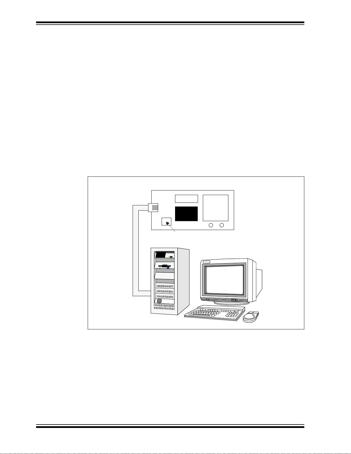
Figure 1-1 shows the setup for the MPLAB Starter Kit for PIC24H MCUs. The USB
connection provides communication and power to the board. As soon as the starter kit
is powered through the USB cable, the preloaded demonstration starts.
FIGURE 1-1: MPLAB STARTER KIT FOR PIC24H MCUs SETUP
®
2000 SP4, Windows XP SP2, or Windows Vista (32-bit)
Operating System for this release. The 64-bit Windows Vista Operating
System is not supported at this time.
(1)
Operating
DS51780A-page 8 © 2008 Microchip Technology Inc.
Page 13
Chapter 2. Starter Kit Demo
S2S1
X
Y
Z
b
MPLAB® STARTER KIT
FOR PIC24H MCU
h
Welcome
This chapter describes the MPLAB® Starter Kit for PIC24H Microcontrollers
demonstration that is preloaded on the PIC24H MCU device, which showcases the
multitasking of accelerometer sensing, the OLED display, speech playback, and the
switch press monitor. This software application demonstrates how to use the MPLAB
Starter Kit for PIC24H MCUs for signal capture and processing of the sensor signal,
speech decoding and playback, and controlling the OLED display.
A detailed explanation of the starter kit hardware is provided in Chapter
4. “Hardware”.
Topics covered include:
• Running the Demo
• Understanding the Demo
• Other Demo Code Examples
2.1 RUNNING THE DEMO
T o run the demo, follow these steps:
1. Power-up the starter kit by connecting the board to the USB port of a computer.
You should briefly see a pop-up message in the system tray that states (1) new
hardware has been found, (2) drivers are being installed, and (3) new hardware
is ready for use. If you do not see these messages and the starter kit does not
work, try reconnecting the USB cable. If reconnecting the USB cable does not
work, refer to Section 3.8 “Troubleshooting”.
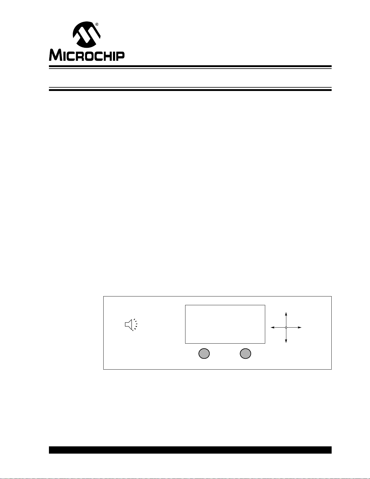
When powered up, an audible welcome message is played while simultaneously
displaying the Start-up screen on the OLED display (see Figure 2-1).
MPLAB® STARTER KIT FOR PIC24H
MICROCONTROLLERS USER’S GUIDE
FIGURE 2-1: START-UP SCREEN
© 2008 Microchip Technology Inc. DS51780A- page 9
Page 14
MPLAB® Starter Kit for PIC24H Microcontrollers User’s Guide
Acc. Graph
Ext. Sensor
Orientation
Games
S2S1
X
Y
Z
PIC24H Starter Kit
b
S1
S2
X
Y
Z
X
Y
Z
Acc. Graph
Ext. Sensor
Orientation
Games
S2S1
X
Y
Z
PIC24H Starter Kit
b
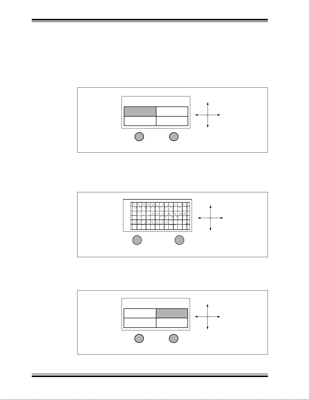
After the start-up exercise, the Home screen appears on the OLED display, as
shown in Figure 2-2.
The Home screen has four cells from which to choose: Accelerometer (Acc.)
Graph, External (Ext.) Sensor, Orientation and Games. The starter kit can be
maneuvered by tilting it about the X and Y axes. Based on the direction of tilt, one
of the four cells is highlighted for selection. Switch S1 or S2 can be pressed to
select the highlighted cell.
FIGURE 2-2: STARTER KIT HOME SCREEN
2. Selecting the Acc. Graph cell starts the application, which captures the triaxial
outputs of the accelerometer and displays them on the OLED display as a graph,
as shown in Figure 2-3. Switch S1 or S2 can be pressed at any time to return to
the Home screen.
FIGURE 2-3: ACCELEROMETER GRAPH
3. Selecting the Ext. Sensor cell (see Figure 2-4) starts the application, which
captures the output of the external sensor that can be plugged-in at points TP12
and TP11.
FIGURE 2-4: SELECTING THE EXTERNAL SENSOR OPTION
DS51780A-page 10 © 2008 Microchip Technology Inc.
Page 15

Starter Kit Demo
Connect External Sensor...
S2S1
X
Y
Z
External Sensor Demo
b
S1
S2
V
X
Y
Z
Acc. Graph
Ext. Sensor
Orientation
Games
S2S1
X
Y
Z
PIC24H Starter Kit
b
Before displaying the external sensor signal an information screen is displayed,
which prompts the user to plug-in an external sensor, as shown in Figure 2-5.
FIGURE 2-5: EXTERNAL SENSOR PROMPT
Switch S1 can be pressed to slow down or speed up the display (see Figure 2-6)
in case the displayed signal is too fast or too slow.
FIGURE 2-6: EXTERNAL SENSOR SIGNAL
Switch S2 can be pressed at any time to return to the Home screen.
4. Selecting the Orientation cell (see Figure 2-7) starts the application, which
indicates the orientation of the starter kit.
Patterns are displayed on the OLED display and messages are played out on the
speaker indicating Portrait, Landscape and Plane orientations (see Figure 2-8).
The acceleration in each of the axes is displayed on the left side of the screen as
a fraction of gravitational acceleration constant on earth, 1g = 9.8 m/s
FIGURE 2-7: SELECTING THE ORIENTATION OPTION
2
.
© 2008 Microchip Technology Inc. DS51780A-page 11
Page 16

MPLAB® Starter Kit for PIC24H Microcontrollers User’s Guide
S2S1
X
Y
Z
X: 0g
Y: +1g
Z: 0g
Landscape
Home
Bomber Jet
Snake
S2S1
X
Y
Z
Games
b
X
Y
Z
S2S1
FIGURE 2-8: ORIENTATION PATTERNS
5. Selecting the Games cell displays a new screen with three cells: Home,
Bomber Jet and Snake, as shown in Figure 2-9.
FIGURE 2-9: GAMES SCREEN
Selecting the Home cell will return you to the Home screen.
6. Selecting the Bomber Jet cell starts the Bomber Jet game.
The Jet can be maneuvered on the X and Y planes of the display by tilting the
starter kit about X and Y axes. Asteroids and alien ships are encountered in the
game. The jet should be maneuvered such that it doesn’t collide with the asteroid, alien ship, and isn’t hit by a missile from the alien ship. Pressing switch S1
turns on a protective shield, momentarily. The shield will destroy any asteroid or
alien ship missile in its path. Pressing S2 releases missiles from the Bomber Jet.
The alien ships and the asteroids are destroyed when hit by the missiles from the
Bomber Jet. See Figure 2-10 for an example of the display during game play .
FIGURE 2-10: BOMBER JET GAME
DS51780A-page 12 © 2008 Microchip Technology Inc.
Page 17

Starter Kit Demo
S2S1
X
Y
Z
Bomber Jet
b
Mission Accomplished!
Score: 1000
Press switch to continue...
S2S1
X
Y
Z
S2S1
X
Y
Z
Snake
b
Snake is full grown!
Score: 350
Press switch to continue...
The score increases whenever a missile fired by the Bomber Jet missile strikes
an alien ship or an asteroid. Using the protective shield decreases the score. The
game automatically exits to a Score screen after achieving a score of 1000 or
when hit by an alien missile, or colliding with an alien ship or asteroid (see
Figure 2-11).
FIGURE 2-11: BOMBER JET GAME SCORE
After the Score screen appears, Switch S1 or S2 can be pressed at any time to
return to the Games screen.
7. Selecting the Snake cell starts the Snake game.
The snake can be maneuvered on the X and Y plane of the display by tilting the
starter kit about X and Y axes. Multiple snake food appears, which the snake
must eat. The snake grows in size when it eats. The snake should be maneuvered to eat the food such that it doesn’t collide with any of the four walls. See
Figure 2-12 for an example of the display during game play.
FIGURE 2-12: SNAKE GAME
The score increases if the snake eats food. The game automatically exits to a
Score screen after the snake grows a tail length of 25 rings or the snake hits any
of the four walls (see Figure 2-13).
FIGURE 2-13: SNAKE GAME SCORE
© 2008 Microchip Technology Inc. DS51780A-page 13
After the Score screen appears, switch S1 or S2 can be pressed at any time to
return to the Games screen.
Page 18

MPLAB® Starter Kit for PIC24H Microcontrollers User’s Guide
ADC
PIC24H MCU
Wide Range of Sensors
ADC
OC
Speaker
Triaxial
Analog
Accelerometer
PMP
OLED
Display
(128 x 64)
2.2 UNDERSTANDING THE DEMO
The PIC24H MCU device on the starter kit is pre-programmed with the main application
demonstration. The CD that accompanies the starter kit also contains the main application code. As shown in Figure 2-14, this sample application uses the board to capture the triaxial acceleration signals from the accelerometer, and plays speech
messages through the speaker with a visual display on the OLED display.
The board also features conditioning circuitry that provides the user the flexibility of
plugging in a wide range of sensors and performing signal processing on the captured
sensor signals.
Detailed descriptions of the basic modules are provided in Chapter 4. “Hardware”.
The following sections give a brief functional description of these modules.
FIGURE 2-14: STARTER KIT BOARD
2.2.1 Accelerometer Interface
The starter kit has a triaxial analog accelerometer. The three (X, Y and Z) acceleration
outputs are captured using the ADC module on the PIC24H MCU device. The
ADC-captured accelerometer samples are processed differently in the PIC24H MCU
based on the game chosen.
2.2.2 OLED Display Interface
The starter kit has a 128 x 64 OLED display. Different screens are displayed for the user
to choose from. Depending on the stimulus obtained from the accelerometer and the
switches, different screens are displayed, signals are graphed and games are
controlled.
2.2.3 Speaker Interface
The speaker plays messages. The speech messages are compressed using the G .71 1
A-law and are stored in the program memory of the PIC24H. The PIC24H decodes the
compressed data and generates PWM signals which are demodulated before being
output through the speaker.
DS51780A-page 14 © 2008 Microchip Technology Inc.
Page 19

2.2.4 External Sensor Interface
The starter kit features an analog conditioning circuit which can be used by the user to
plug in a wide range of external sensors. The differential output of the sensor flows
through a differential amplifier and an anti-aliasing filter before being sampled by the
on-chip ADC.
2.3 OTHER DEMO CODE EXAMPLES
The starter kit software CD includes another demo code example,
External_Sensor_Demo.
The External_Sensor_Demo code example demonstrates the low-cost sensor signal
capture and processing. When a sensor is plugged into the analog conditioning
circuitry the code example captures the sensor signal through the ADC channel. The
captured discrete time sensor signal can be processed inside the code example.
Instructions are provided in the source file as to where user desired signal processing
routines need to be added to process the sensor signal captured by the ADC.
The characteristics of the external analog sensor that can be used are provided in
Section 4.1.4 “Analog Conditioning Circuitry”.
Starter Kit Demo
© 2008 Microchip Technology Inc. DS51780A-page 15
Page 20

MPLAB® Starter Kit for PIC24H Microcontrollers User’s Guide
NOTES:
DS51780A-page 16 © 2008 Microchip Technology Inc.
Page 21

MPLAB® STARTER KIT FOR PIC24H
MICROCONTROLLERS USER’S
Chapter 3. Develop an Application
The MPLAB Starter Kit for PIC24 MCUs may be used with MPLAB® IDE, the free
integrated development environment available on Microchip’s web site. MPLAB IDE
allows the starter kit to be used as an in-circuit debugger as well as a programmer for
the featured device.
In-circuit debugging allows you to run, examine, and modify your program for the
device embedded in the starter kit hardware. This greatly assists you in debugging your
firmware and hardware together.
Special starter kit software interacts with the MPLAB IDE application to run, stop, and
single-step through programs. Breakpoints can be set and the processor can be reset.
Once the processor is stopped, the register’s contents can be examined and modified.
For more information on how to use MPLAB IDE, reference the following
documentation:
• MPLAB
• MPLAB
• MPLAB
This chapter includes the following:
• Installing the Hardware and Software
• Setting Up an Example Application for Debug
• Running the Example Application
• Debugging the Example Application
• Programming the Debugged Application
• Creating Other PIC24H MCU Applications
• Determining Device Support and Reserved Resources
• Troubleshooting
• Settings Dialog, Info Tab
®
IDE User’s Guide (DS51519)
®
IDE Quick Start Guide (DS51281)
®
IDE On-line Help
3.1 INSTALLING THE HARDWARE AND SOFTWARE
To install the hardware:
If you have not already set up the hardware to run the demo, follow these steps:
1. Power-up the starter kit by connecting the board to the USB port of a computer.
You should briefly see a pop-up balloon in the system tray that states (1) new
hardware has been found, (2) drivers are being installed, and (3) new hardware
is ready for use. If you do not see these messages and the starter kit does not
work, try reconnecting the USB cable. If reconnecting the USB cables does not
work, see Section 3.8 “Troubleshooting”.
2. When powered up, the application starts and runs as described in Section 2.1.
To install the software:
Run the CD-ROM enclosed with the starter kit and install the software as directed.
© 2008 Microchip Technology Inc. DS51780A-page 17
Page 22

MPLAB® Starter Kit for PIC24H Microcontrollers User’s Guide
2
3
4
1
3.2 SETTING UP AN EXAMPLE APPLICATION FOR DEBUG
The MPLAB IDE software that is installed on your PC by the starter kit CD-ROM automatically opens an example application that you may use to examine debug features
of the starter kit.
To prepare the application for debug:
1. Launch MPLAB IDE. The example application project and related workspace will
open. For information on projects and workspaces, see the MPLAB IDE
documentation mentioned at the beginning of this chapter.
2. Select Projec t>Build Al l
visible in the Build tab of the Output window.
3. Select Debugger>Select T ool>Starter Kits
kit debug features (Figure 3-1): (1) the status bar will show Starter Kits as the
debug tool, (2) a Starter Kit debug toolbar will be added, (3) the Debugger menu
will change to add Starter Kit debug functions and (4) the Output window will display communication status between MPLAB IDE and the stater kit on the Starter
Kit Debugger tab.
Also, several device resources are used for debug. For details, see
Section 3.7 “Determining Device Support and Reserved Resources”.
FIGURE 3-1: STARTER KIT AS DEBUG TOOL
to build the application code. The build’s progress will be
. MPLAB IDE will change to add starter
4. Select Debugger>Program
MCU device on the starter kit. The debug programming progress will be visible
in the Start e r Kit tab of the Output window.
Note: Debug executive code is automatically programmed in the upper program
memory of the starter kit device when the starter kit is selected as a debugger. Debug code must be programmed into the target device to use the
in-circuit debugging capabilities of the starter kit.
DS51780A-page 18 © 2008 Microchip Technology Inc.
to program the application code into the PIC24H
Page 23

3.3 RUNNING THE EXAMPLE APPLICATION
The starter kit executes in either real-time (Run) or steps (Step Into, Step Over,
Animate). Real-time execution occurs when you select Run in MPLAB IDE. Once the
device code is halted, either by Halt or a breakpoint, you can step.
The toolbar buttons shown in Table 3-1 can be used for quick access to commonly
used debug operations:
TABLE 3-1: TOOLBAR BUTTONS
Debugger Menu Debug Toolbar Debugger Menu DSK Toolbar
Run Program
Halt Read
Animate
Step Into
Step Over
Reset
Breakpoints
To see how these options function, do the following:
1. Select Debugger>Reset>Processor Reset
2. Select Debugger>Run
3. Select Debugger>Halt
arrow will mark the line of code in the File window where the program halted.
4. Select Debug ger> Step Into
once. The green solid arrow will move down one line of code in the File window.
Click the button several times to step through some code.
5. Select Debugger>Reset>Processor Reset
again. The arrow will disappear, meaning the device is reset.
or click Run. Observe how the application operates.
or click Halt to stop the program execution. A green solid
or click Step Into to step the program execution
Develop an Application
or click Reset to reset the program.
click Reset to reset the program
3.4 DEBUGGING THE EXAMPLE APPLICATION
For the example code given, everything works fine. However, when you are developing
code, it will likely not work the first time and may need to be debugged. MPLAB IDE
provides an editor and several debug features, such as breakpoints and Watch
windows, to aid in application code debugging.
This section includes:
• Editing Application Code
• Using Breakpoints and Mouseovers
• Using Watch Windows
© 2008 Microchip Technology Inc. DS51780A-page 19
Page 24

MPLAB® Starter Kit for PIC24H Microcontrollers User’s Guide
3.4.1 Editing Application Code
To view application code so it may be edited, do one of the following:
1. Select Edit>New
existing code file.
2. Double click a file in the Project window to open an existing code file. See an
example Project window in Figure 3-2.
FIGURE 3-2: EXAMPLE PROJECT
to create new code or Edit>Open to search for and open an
For more information on using the editor to create and edit code, see MPLAB Editor
Help.
3.4.2 Using Breakpoints and Mouseovers
T o set a breakpoint in code:
1. Double Click the Gutter – Double click in the window gutter next to the line of
code where you want the breakpoint. Double click again to remove the
breakpoint.
Note: Double click must be set up for breakpoints. See the Edit>Properties
ASM/C/BAS File Type tab, and the check box for “Double-click
Toggles Breakpoint”.
2. Pop-up Menu – Place the cursor over the line of code where you want the breakpoint. Then, right click to pop up a menu and select “Set Breakpoint”. Once a
breakpoint is set, “Set Breakpoint” will become “Remove Breakpoint” and
“Disable breakpoint”. Other options on the pop-up menu under Breakpoints are
for deleting, enabling, or disabling all breakpoints.
3. Breakpoint Dialog – Open the Breakpoint dialog (Debugger>Breakpoints
set, delete, enable or disable breakpoints. See MPLAB IDE Help for more
information on this dialog.
DS51780A-page 20 © 2008 Microchip Technology Inc.
,
) to
Page 25

A breakpoint set in code will appear as a red hexagon with a “B” as shown in
Figure 3-3.
FIGURE 3-3: EXAMPLE BREAKPOINT
Develop an Application
Once code is halted, hovering over variables pops up the current value of those
variables (see Figure 3-3.)
Note: This feature must be set up. See the Edit>Properties, Tooltips tab, and
check the “Enable Variable Mouseover Values” check box.
3.4.3 Using Watch Windows
To use a Watch window:
1. The Watch window is made visible on the desktop by selecting View>Watch
contains four selectable Watch views (via tabs) in which to view variables (SFRs,
symbols and absolute addresses).
2. Select an SFR or Symbol from the list and click the related Add button to add it
to the Watch window. Or click the “Address” column and enter an absolute
address.
A Watch window populated with SFRs and Symbols will look like Figure 3-4. For more
information on using Watch windows, see MPLAB IDE Help.
FIGURE 3-4: EXAMPLE WATCH
. It
© 2008 Microchip Technology Inc. DS51780A-page 21
Page 26

MPLAB® Starter Kit for PIC24H Microcontrollers User’s Guide
3.5 PROGRAMMING THE DEBUGGED APPLICATION
When the program is successfully debugged and running, the next step is to program
the device for stand-alone operation in the finished design. When doing this, the
resources reserved for debug are released for use by the application.
To program the application, use the following steps:
1. Disable Starter Kits as a debug tool by selecting Debugger>Select Tool>None
2. Select Starter Kits as the programmer in the Programmer>Select Programmer
menu.
3. Select Programmer>Program
Now the starter kit will run independently.
3.6 CREATING OTHER PIC24H MCU APPLICATIONS
This starter kit is just one way to use Microchip PIC24H MCUs in an application. Other
tools and resources exist to support these devices.
• PIC MCU Development Boards – Many boards are available for developing appli-
cations. See our web site (http://www.microchip.com/) under Design>Development Tools>Demo Boards>PIC M CU.
• MPLAB C Compiler for dsPIC
optimization options than the student version for full-scale development. See
http://www.microchip.com/c30.
• Application Notes – Example applications with code for using PIC24H MCU
features. See our web site (http://www.microchip.com/) under Design>App Notes
& Source Code>16-bit PIC MCUs & dsPIC DSCs.
.
®
DSCs and PIC24 MCUs, Full Version – More
.
3.7 DETERMINING DEVICE SUPPORT AND RESERVED RESOURCES
Due to the built-in in-circuit debugging capability of ICD devices and the ICSP™
function offered by the debugger, the starter kit uses some on-chip resources when
debugging. It also uses program memory and file register locations in the target device
during debugging. These locations are not available for use by user code. In the
MPLAB IDE, registers marked with an “R” in register displays represent reserved
registers.
For information on device resources that are needed for in-circuit debugging, please
refer to the MPLAB ICD 2 Help, found in MPLAB IDE under Help>Topics
reserved resource information found under “Resources Used By MPLAB ICD 2” is the
same for the starter kit.
. The device
DS51780A-page 22 © 2008 Microchip Technology Inc.
Page 27

3.8 TROUBLESHOOTING
3.8.1 Debug Connection Problems
While using the starter kit as a debugger, you may get the error “Unable to Enter Debug
Mode” when programming the device. This can result from communication being lost
between the starter kit and MPLAB IDE. To resolve this:
1. Unplug the USB cable from the starter kit.
2. Plug the USB cable back into the starter kit.
MPLAB IDE should automatically reconnect to the starter kit. If this does not work, do
the following:
1. Check the USB connection between the PC and starter kit at both ends.
2. If using a USB hub, make sure it is powered.
3. Make sure the USB port is not in use by another device.
3.8.2 Programming Problems
If during the course of developing your own application you can no longer program the
device on the starter kit, you may have set device Configuration bits to code-protect or
some other state that prevents programming. T o view the settings of the Configuration
bits, select Configure>Configuration Bits
Develop an Application
.
3.8.3 Build Problems
When using the starter kit as a debugger, make sure that the Build Configuration
(drop-down list on the toolbar or item on the Debugger menu) is set to “Debug” or your
code will not build correctly for debugging. When using the starter kit as a programmer,
make sure that the Build Configuration is set to “Release” or your code will not build
correctly for programmi ng .
3.9 SETTINGS DIALOG, INFO TAB
When you select Debugger>Settings or Programmer Settings, you will open the Starter
Kit Settings dialog.
Currently, there is only one (Info) tab on this dialog, displaying the following
information:
• Firmware Version: The version of firmware on the starter kit board.
• Debug Exec Version: The version of the debug executive that is loaded into the
device program memory to enable debug operation.
© 2008 Microchip Technology Inc. DS51780A-page 23
Page 28

MPLAB® Starter Kit for PIC24H Microcontrollers User’s Guide
NOTES:
DS51780A-page 24 © 2008 Microchip Technology Inc.
Page 29

MPLAB® STARTER KIT FOR PIC24H
AN4
PIC24H MCU
Wide Range of Sensors
AN7
OC1
Speaker
Triaxial
Analog
Accelerometer
OLED
Display
AN5
AN6
PMD7-PMD0
PMRD
PMWR
Low-pass
Filter
Device
Audio Power
Amplifier
Low-pass
Filter
Differential
Amplifier
(128 x 64)
PMCS1
PMA0
MICROCONTROLLERS USER’S GUIDE
Chapter 4. Hardware
This chapter provides a functional overview of the hardware used in the MPLAB Starter
Kit for PIC24H MCUs and identifies the major hardware components.
Topics covered include:
• Application Functional Overview
• Debug Functional Overview
• Board Components
4.1 APPLICATION FUNCTIONAL OVERVIEW
The block diagram shown in Figure 4-1 illustrates the mainstream operation of the
starter kit.
FIGURE 4-1: STARTER KIT APPLICATION BLOCK DIAGRAM
© 2008 Microchip Technology Inc. DS51780A-page 25
Page 30

MPLAB® Starter Kit for PIC24H Microcontrollers User’s Guide
+X
+Y
+Z
Top Side
Gravity Vector
C
R
Pwm Signal From OCPWM Low-pass Filter Demodulated Audio Signal
4.1.1 Accelerometer Interface
The starter kit has a triaxial analog accelerometer (see schematics in Figure A-2). The
accelerometer has three analog outputs, one for each of the three spatial dimensions
(3D - X, Y , and Z). These three acceleration outputs are captured using the ADC inputs
AN4, AN5 and AN6, respectively, on the PIC24H MCU device.The ADC is set to
perform simultaneous sampling. The direction of acceleration and associated spatial
dimensions can be observed in the Figure 4-2.
FIGURE 4-2: DIRECTION OF ACCELERATION AND ASSOCIATED
SPATIAL DIMENSIONS FOR THE T R IAXIAL ANALOG
ACCELEROMETER
4.1.2 OLED Display Interface
The starter kit has a 128 x 64 pixel, monochrome organic LED array , which provides a
wide range of graphics and alphanumeric display options. It is interfaced to the PIC24H
MCU through the Parallel Master Port (PMP) module. The application uses the
Microchip Graphics Library to communicate with the OLED display.
4.1.3 Speaker Interface
The speech messages are compressed using the G.711 A-law and are stored in the
program memory of the PIC24H MCU. The wave files were G .711 compressed by using
the dsPIC33F Speech Encoder Utility for G.711 provided on the CD and also available
on the Microchip web site. When the demo application is running, the compressed
speech messages are loaded from the program memory and decompressed using the
G711 A-law decode algorithm and played out as a Pulse Width Modulated (PWM)
signal using the output compare module on the PIC24H. This signal is passed through
a 4th-order low-pass filter. This behaves like an integrator, whose output signal
amplitude and frequency depends on the duty cycle of the input PWM waveform. The
PWM frequency should be an integral multiple of the audio sampling rate. The output
of this low-pass filter feeds an audio amplifier. The speaker is driven by an audio power
amplifier (LM4853 Boomer). The speaker has a frequency range of 600 Hz to 22 kHz,
with 8 Ohm impedance and rated power of 1W. See the schematics in Figure A-3.
FIGURE 4-3: PWM DEMODULATION
DS51780A-page 26 © 2008 Microchip Technology Inc.
Page 31

Hardware
Gain
R
f
R
i
---- - V
TP11VTP12
–()=
R
f
R57 R58==
R
i
R51 R53==
4.1.4 Analog Conditioning Circuitry
The starter kit features an analog conditioning circuit (see schematics in Figure A-4),
which can be used by the user to plug in a wide range of external analog sensors. The
analog conditioning circuit has a differential amplifier followed by an anti-aliasing low
pass filter. The gain of the differential amplifier is given by Equation 4-1 in terms of the
resistors used and differential input voltages at input points TP11 and TP12. The gain
is fixed at 100. Any sensor with a differential compensated output voltage of less than
33mV can be used.
EQUATION 4-1: DIFFERENTIAL AMPLIFIER GAIN
The anti-aliasing filter is a 2nd-order low-pass filter, with a cut-off frequency of ~500 Hz
(483.78 Hz). The highest frequency of the base band sensor signal is assumed to be
less than 500 Hz. The output of the low-pass filter is connected to the ADC input AN7
on the PIC24H MCU device.
© 2008 Microchip Technology Inc. DS51780A-page 27
Page 32

MPLAB® Starter Kit for PIC24H Microcontrollers User’s Guide
PIC18F67J50 Device
Status
LEDs
PIC24H MCU
Device
USB Mini-B
Jack
Serial EEPROM
25LC010A
3.3V LDO
Regulator
12 MHz
Crystal
SPI
ICSP™
4.2 DEBUG FUNCTIONAL OVERVIEW
The block diagram shown in Figure 4-4 illustrates the debugging/programming
operation of the starter kit.
FIGURE 4-4: STARTER KIT DEBUG BLOCK DIAGRAM
The starter kit, with its built-in debugger/programmer, provides an all-in-one solution for
debugging and programming applications using MPLAB IDE. Also, no additional
external power supply is needed as power is supplied by the host PC’s USB port. See
the schematics in Figure A-7 and Figure A-8.
The starter kit’s debugging/programming operations are controlled by a PIC18F67J50
MCU running at 48 MHz. The PIC18F67J50’s built-in USB engine provides the
communications interface between the starter kit and the host PC.
Power to the starter kit is provided via USB, whose nominal 5V unregulated supply is
regulated by a Microchip MC1727 3.3V low-dropout (LDO) linear regulator. Proper
starter kit main system power is indicated by the green LED, D1.
The PIC18F67J50 MCU accomplishes debugging or programming of the target
PIC24HJ128GP504 by controlling the target’s PGC1/EMUC1 and PGD1/EMUD1
signals. Target power is switched on/off via a low V
CE saturation PNP transistor
configured as a high-side switch. T arget clocking is also provided by the PIC18F67J50
MCU.
A Microchip 25LC010A serial EEPROM is used to store the starter kit’s serial number
and debug control information.
DS51780A-page 28 © 2008 Microchip Technology Inc.
Page 33

4.3 BOARD COMPONENTS
A5
A7
M
D2 D3 D4 A1 A2 A3 A4
D1
D5
D6
D7
A8
A11
A9
A10
A6
®
Figure 4-5 identifies the key starter kit hardware components. Table 4-1 provides
descriptions for the hardware components.
FIGURE 4-5: STARTER KIT
Hardware
TABLE 4-1: STARTER KIT HARDWARE COMPONENT DESCRIPTIONS
Ref Component Ref Component
D1 Mini-B USB Connector (J1) A3 Audio Power Amplifier (U7)
D2 MCP1727 (U1) A4 Anti-Aliasing Low-Pass Filter (Speech) (U6: A, B)
D3 Low V
D4 Debug St at us LED (D18) A6 Switch S1
D5 System Power STATUS LED (D19) A7 Switch S2
D6 PIC18F67J50 MCU (U2) A8 Differential Amplifier (External Sensor) (U4: A)
D7 25LC010A SERIAL EEPROM (U3) A9 Anti-Aliasing Low-Pass Filter (External Sensor) (U4: B)
A1 PIC24HJ128GP504 (MCU) (U5) A10 Sensor Differential Inputs (External Sensor) (TP11 and TP12)
A2 Speaker (SP2) A11 Triaxial Analog Accelerometer (U8)
Legend:
D# = Debug components
A# = Audio components
CE Saturation PNP Transistor Switch (Q1) A5 OLED Display (LED)
© 2008 Microchip Technology Inc. DS51780A-page 29
Page 34

MPLAB® Starter Kit for PIC24H Microcontrollers User’s Guide
4.3.1 Debug Components
The following components support the debug function of the starter kit. See Appendix
A. “Schematics” for debug schematics.
4.3.1.1 MINI-B USB CONNECTOR (J1)
Provides system power and bidirectional communication between the host PC and
starter kit.
4.3.1.2 MCP1727 (U1)
3.3V Linear regulator. Regulates the USB unregulated voltage to 3.3 volts (with respect
to V
SS) and supplies the starter kit with system power.
4.3.1.3 LOW V
CE SATURATION PNP TRANSIS TOR SWITCH (Q1)
Provides target power (via high-side switching) to the PIC24HJ128GP504 (and
ancillary circuitry) via control by the PIC18F67J50 programming/debugging MCU.
4.3.1.4 DEBUG STATUS LED (D18)
When lit, indicates that communication between the starter kit and MPLAB IDE has
been successfully established.
4.3.1.5 SYSTEM POWER STATUS LED (D19)
When lit, indicates that the starter kit is powered via the USB.
4.3.1.6 PIC18F67J50 MCU (U2)
Controls the programming/debugging operations of the target PIC24HJ128GP504
device.
4.3.1.7 25LC010A SERIAL EEPROM (U3)
Provides nonvolatile parameter storage for the PIC18F67J50 MCU.
4.3.2 Application Components
The following components support the application portion of the starter kit. See
Appendix A. “Schematics” for application schematics.
4.3.2.1 PIC24HJ128GP504 (MCU) (U5)
The PIC24HJ128GP504 microcontroller unit (MCU) provides the computation and
processing resource for application development on the starter kit. This MCU features
128 KB of program Flash and 4 KB RAM. The application can either use the on-chip
FRC or the external 12 MHz signal as clock source.
4.3.2.2 SPEAKER (SP2)
The speaker is connected to the Output Compare (OC) module. The OC module
produces the PWM-modulated speech signal that is played through the speaker after
filtering.
DS51780A-page 30 © 2008 Microchip Technology Inc.
Page 35

Hardware
Gain 2
R56
R59
--------- -
⎝⎠
⎛⎞
×=
4.3.2.3 AUDIO POWER AMPLIFIER (U7)
The audio power amplifier is a National Semiconductor, LM4853 Mono 1.5W/Stereo
300 mW amplifier. Gain has been set to 3.3 using the resistors R56 and R59, as shown
in Equation 4-2.
EQUATION 4-2: AUDIO POWER AMPLIFIER GAIN
4.3.2.4 ANTI-ALIASING LOW-PASS FILTER (SPEECH) (U6: A, B)
The PWM signal from the output compare module on the PIC24H MCU device on the
board is demodulated by the PWM low-pass filter. This 4th-order filter uses two op
amps (U6: A and U6: B) on the MCP617 dual op amp IC. The cut-off frequency of the
filter is ~4 kHz.
4.3.2.5 OLED DISPLAY (LED)
The starter kit has a 128 x 64 pixel, monochrome organic LED array , which provides a
wide range of graphics and alphanumeric display options.
4.3.2.6 SWITCH S1 AND SWITCH S2
The starter kit has two press switches, S1 and S2, which are connected to the I/O ports
on the PIC24H MCU device. The functions of these two switches are defined by the
application.
4.3.2.7 DIFFERENTIAL AMPLIFIER (EXTERNAL SENSOR) (U4: A)
The first op amp of the U4 component MCP617 is used to construct the differential
amplifier circuit, which is used in the analog signal conditioning circuit for the external
sensor.
4.3.2.8 ANTI-ALIASING LOW-PASS FILTER (EXTERNAL SENSOR) (U4: B)
The second op amp of the U4 component MCP617 is used to construct the anti-aliasing
low-pass filter circuit, which follows the differential amplifier circuit in the analog signal
conditioning circuit for the external sensor.
4.3.2.9 SENSOR DIFFERENTIAL INPUTS (EXTERNAL SENSO R) (TP11 AND
TP12)
The interface holes, TP1 1 and TP12, can be used to connect the differential outputs of
the external sensor. TP11 takes in the positive node and TP12 the negative node.
4.3.2.10 TRIAXIAL ANALOG ACCELEROMETER (U8)
The starter kit features a triaxial analog accelerometer, BMA140, from Bosch
Sensortec.
© 2008 Microchip Technology Inc. DS51780A-page 31
Page 36

MPLAB® Starter Kit for PIC24H Microcontrollers User’s Guide
NOTES:
DS51780A-page 32 © 2008 Microchip Technology Inc.
Page 37

MPLAB® STARTER KIT FOR PIC24H
MICROCONTROLLERS USER’S GUIDE
Appendix A. Schematics
This appendix provides the following schematics for the MPLAB Starter Kit for PIC24H
Microcontrollers:
Section A.1 “Application Schematics”:
• Figure A-1: Processor Schematic
• Figure A-2: Accelerometer Schematic
• Figure A-3: Speaker Schematic
• Figure A-4: Differential Amplifier and Low-Pass Filter Schematic
• Figure A-5: Organic LED (OLED) Display Schematic
• Figure A-6: User Switches and Test Points Schematics
Section A.2 “Debug Schematics”:
• Figure A-7: USB Interface/Target Power Switching and Debug Input and Control
Schematics (Sheet 1 of 2)
• Figure A-8: USB Interface/Target Power Switching and Debug Input and Control
Schematics (Sheet 2 of 2)
© 2008 Microchip Technology Inc. DS51780A-page 33
Page 38

MPLAB® Starter Kit for PIC24H Microcontrollers User’s Guide
VSS
VDD
AVSS
AVDD
AVDD
VSS
VDD
SWITCHED_+3.3V
SWITCHED_+3.3V
AV
DD
R28
10R
C25
0.1
UF
R29
10R
AUDIO_OUT
SWITCH_S2
TARGET_REFERENCE_CLOCK
SWITCHED_+3.3V
SWITCH_S1
SENSOR
ACCEL_Z
ACCEL_Y
ACCEL_X
C24
0.1 UF
33
32
31
30
29
28
27
26
25
24
23
RB4
RA8
OSC0
OSC1
RC2
RC1
RC0
RB3
RB2
QFN44_8X8
U5
RB9
RC6
RC7
RC8
RC9
DISVREG
V
CAP/VDDCORE
RB13
RB12
RB11
RB10
PMPD4
PMPD5
PMPD6
PMPD7
44
43
42
41
40
39
38
37
36
35
34
RB8
RB7
RB6
RB5
RC5
RC4
RC3
RA9
RA4
RA10
RA7
RB14
RB15
RA0
RA1
RB0
RB1
MCLR
PMPD3
PMPA0
PMPD2
PMPD1
PMPD0
PMPRD
1
2
3
4
5
6
7
8
9
10
11
121314
15
16
17
18
192021
22
PMPWR
PMCS1
RESET
TARGET_CLOCK
TARGET_DATA
R27
330R
R26
10K
SWITCHED_+3.3V
TARGET_MCLR
C18
10 uF
AVDD
U8
BMA140
ACCEL_X
ACCEL_Y
ACCEL_Z
11
10
9
8
7
126
1
2
3
4
5
AMUX
X.OUT
Y.OUT
Z.OUT
TEST
SEL.0
SEL.1
VDD1
VDD2
GND1
GND2
ST
C20
0.1 uF
C36
10 uF
A.1 AP PLICATION SCHEMATICS
FIGURE A-1: PROCESSOR SCHEMATIC
FIGURE A-2: ACCELEROMETER SCHEMATIC
DS51780A-page 34 © 2008 Microchip Technology Inc.
Page 39

FIGURE A-3: SPEAKER SCHEMATIC
AUDIO_OUT
C32
0.1 uF
R61
9.31K
R62
19.1K
C38
2700 pF
C37
3300 pF
5
6
U6:B
MCP61-I/SN
7
R50
8.45K
R54
12.4K
C26
2700 pF
C34
5600 pF
VINV+
VINB-
MCP617-I/SN
U6:A
C31
0.1
UF
SWITCHED_+3.3V
4
1
8
3
2
VINA+
VINA-
C33
1.2
UF
R59
20K
R60
100K
R56
33K
LM4853MM_MSOP10
SWITCHED_+3.3V
SP2
GC0251K-ND
C39
100
UF
R63
1K
C30
1 uF
C29
0.1 uF
U7
Left_IN
Left_OUT
Shutdown
V
DD
HP_IN BLT_OUT+
GND
Bypass
Right_IN Right_OUT
10
9
8
7
6
1
2
3
4
5
AVDD
C28
47 nF
C27
0.1 uF
MCP617-I/SN
R52
R55
7.87K
13.3K
C35
22000 pF
SENSOR
VINA+
VINA-
8
1
4
2
3
U4:A
R58
100K
VINV+
VINB-
5
6
U4:B
7
MCP617-I/SN
1K
1K
R57
100K
R51
R53
TP11
TP12
Schematics
FIGURE A-4: DIFFERENTIAL AMPLIFIER AND LOW-PASS FILTER SCHEMATIC
© 2008 Microchip Technology Inc. DS51780A-page 35
Page 40

MPLAB® Starter Kit for PIC24H Microcontrollers User’s Guide
LED1
VPP
VPP
SWITCHED_+3.3V
L3
D5
100 uH
C45
C44
10
1
MBR0520L
D3
G1
Q4
MGSF1N02LT1
S2
R38
.12 ohm 1%
R40
930K 1%
R39
110K 1%
C43
1000 pF
C40
6.8
C42
4.7
C41
1
R37
820K
LED_OLED_HS1101A
NC
GND
SW
VDD2
FB
SENSE
V
BREF
VDD1
CB6
PS
CS
RES
A0
WR
RD
D0
D1
D2
D3
D4
D5
D6
D7
IREF
NC
VCOMH
IREF
PMPD7
PMPD6
PMPD5
PMPD4
PMPD3
PMPD2
PMPD1
PMPD0
VCOMH
PMPRD
PMPWR
PMPA0
RESET
PMCS1
SWITCHED_+3.3V
VBREF
RESE
FB
SWITCHED_+3.3V
SW
1
2
3
4
5
6
7
8
9
10
11
12
13
14
15
16
17
18
19
20
21
22
23
24
25
26
27
TP7
TP8
TP9
TP10
SWITCHED_+3.3V
R30
10K
S1
B3F-1002-G
C23
0.1
UF
1
2
4
3
SWITCH_S1
R31
10K
S2
B3F-1002-G
0.1
UF
C22
SWITCH_S2
1
2
3
4
FIGURE A-5: ORGANIC LED (OLED) DISPLAY SCHEMATIC
FIGURE A-6: USER SWITCHES AND TEST POINTS SCHEMATICS
DS51780A-page 36 © 2008 Microchip Technology Inc.
Page 41

Schematics
U2
PIC18F67J50_TQFP64
V
SS
VSS
VDD
VDD
VSS
VDD
VSS
AVDD
AVSS
+3.3V
HOST_LED_RUN_DEBUG
TARGET_REFERENCE_CLOCK
TP5
CHIP_SELECT_SERIAL_EEPROM_1
POWER_GOOD_+3.3V
R20
330
R21
330
330
R23
TARGET_DATA
TARGET_CLOCK
R24
4.7K
R22
4.7K
+3.3V
R25
10K
R17
10K
SWITCH_TO_TARGET_+3.3V
C17
R12
330
Y1
27 pF
12 MHz
C8
27 pF
+3.3V
WRITE_PROTECT_SERIAL_EEPROM1
HOST_ICSP_PGC
HOST_ICSP_PGD
HOST_MASTER_SPI_SDO
HOST_MASTER_SPI_SDI
HOST_MASTER_SPI_SCK
TARGET_MCLR
33
34
35
36
37
38
39
40
41
42
43
44
45
46
47
48
TEST_DEBUG_1
TEST_DEBUG_0
TP2
TP1
+3.3V
R7
200K
R6
200K
HOST_ASYNC_SERIAL_RX1
HOST_ASYNC_SERIAL_TX1
+3.3V
SWITCHED_+3.3V
C5
0.1 uF
C6
1uF
+3.3V
(RF2 – DO NOT USE
Due to USB routing)
D+
D-
C13
10 uF
R2 330
HOST_ICSP_MCLR
1
234
5
7
6
8
9
101112
13
14
15
16
17
18
RF2
19
20
21
22
23
24
25
26
27
28
29
30
31
32
64
63
62
61
60
59
58
57
56
55
54
53
52
51
50
49
RF3/D-
RF4/D+
RF5
RF6
RF7
V
DDCORE/VCAP
RG4
MCLR
RG3
RG2
RG1
RG0
RE0
RE1
RB0
RB1
RB2
RB3
RB4
RB5
RB6/RGD
OSC2/RA6
OSC1/RA7
RB7/PGC
RC5/SDO1
RC4/SDI1
RC3/SCK1
RC2
RE2
RE3
RE4
RE5
RE6
RE7
RD0
RD1
RD2
RD3
RD4/SDO2
RD5/SDI2
RD6/SCK2
RD7
V
USB
ENVREG
RA3
RA2
RA1
RA0
RA5
RA4
RC1
RC0
RC6
RC7
A.2 DEBUG SCHEMATICS
FIGURE A-7: USB INTERFACE/TARGET POWER SWITCHING AND DEBUG INPUT AND CONTROL SCHEMATICS (SHEET 1 OF 2)
© 2008 Microchip Technology Inc. DS51780A -page 37
Page 42

MPLAB® Starter Kit for PIC24H Microcontrollers User’s Guide
Serial EEPROM
Status LED – Debug
PIC18F67J50 Bypass/Decoupling Capacitors
25LC010A_S08_SN
(VDD pin 26 and VSS)
Vcc
Vss
(V
DD pin 38 and VSS)(VDD pin 57 and VSS)
+3.3V +3.3V
+3.3V
C7
1uF
1uF
1uF
C12
C15
+3.3V
D19
GREEN
R14
330
HOST_LED_RUN_DEBUG
USB INTERFACE
(BUS POWERED)
TP3
J1
L1
0R
R5
V
BUS
D-
D+
ID (NC)
1
2
3
4
5
6,7,8,9
0R
R4
C4
0.01uF
C2
0.001uF
R3
200K
C1
0.1uF
C3
2.2uF
3.3V LDO
LINEAR REGULATOR
+3.3V
U1
VIN
MCP1727_DFN8
VOUT
SENSE
CDELAY
PWRGD
GND
SHDN
VIN
VIN
123
4
8
765
R8
200K
C9
C10
C11
D18
0.1uF
1.0uF 0.01uF
2.2K
R9
R13
330R
GREEN
R19
10K
R15
2.2K
R16
330R
C19
47pF
TP4
TP6
ZXTP25020CFH
SYSTEM POWER
INDICATOR
Q1
C3
B1
E2
Logic ‘0’: Connect +3.3V to target
Logic ‘1’: Disconnect +3.3V from target
SWITCH_TO_TARGET_+3.3V
POWER_GOOD_+3.3V
SWITCHED_+3.3V
HOST MCU SWITCHABLE
3.3V REGULATED SUPPY
R10
1K
4
U3
7
3
1
6
5
8
2
C14
1uF
R11
10K
+3.3V
SO
SI
SCK
CS
WP
HOLD
HOST_MASTER_SPI_SDI
HOST_MASTER_SPI_SDO
HOST_MASTER_SPI_SCK
CHIP_SELECT_SERIAL_EEPROM_1
WRITE_PROTECT_SERIAL_EEPROM1
FIGURE A-8: USB INTERFACE/TARGET POWER SWITCHING AND DEBUG INPUT AND CONTROL SCHEMATICS (SHEET 2 OF 2)
DS51780A-page 38 © 2008 Microchip Technology Inc.
Page 43

MPLAB® STARTER KIT FOR PIC24H
MICROCONTROLLERS USER’S GUIDE
Index
A
Accelerometer Interface......................................14, 26
Amplifier Gain .....................................................27
Analog Conditioning Circuitry................................... 27
, 31
B
Board Components............................................ ......29
Board Setup....................................................... ...... ..8
Breakpoints.............................................................. 19
Build Configuration...................................................23
C
Configuration Bits.....................................................23
Customer Notification Service....................................4
Customer Support......................................................5
D
Debug ...................................................................... 28
Executive..........................................................18
Reserved Resources........................................ 22
Setup ................................................................ 18
Debug/Release........................................................23
Demo2 ..................................................................... 15
Demonstration Application.........................................9
Documentation
Conventions........................................................2
Layout................................................................. 1
E
External Sensor Interface ........................................15
H
Halt...........................................................................19
Hardware Installation...............................................17
Host Computer Requirements.................................... 8
I
Install........................................................................17
Internet Address.........................................................4
M
Microchip Internet Web Site.......................................4
MPLAB IDE..............................................................17
O
OLED Display Interface...................................... 14, 26
Operational Requirements.........................................8
Overview....................................................................7
P
Programmer.............................................................22
R
Reading, Recommended................................... ...... ..3
Reserved Resources................................................22
Reset........................................................................19
Run...........................................................................19
S
Schematics
Application
Accelerometer............................................34
Differential Amplifier and Low-Pass Filter.. 35
Processor...................................................34
Speaker .....................................................35
User Switches and Test Points..................36
Debug
USB Interface Schematic/Target
Power Switching Schematic ................37
Setup..........................................................................8
Software Installation.................................................17
Speaker Interface...............................................14
Speech Sampling Interface Schematic....................38
Step..........................................................................19
, 38
, 26
T
Troubleshooting.......................................................23
U
Unable to Enter Debug Mode...................................23
W
Warranty Registration........................................ ...... ..3
Watch Window.........................................................19
WWW Address...........................................................4
© 2008 Microchip Technology Inc. DS51780A-page 39
Page 44

Worldwide Sales and Service
AMERICAS
Corporate Office
2355 West Chandler Blvd.
Chandler, AZ 85224-6199
Tel: 480-792-7200
Fax: 480-792-7277
Techn ical Su pport:
http://support.microchip.com
Web Address:
www.microchip.com
Atlanta
Duluth, GA
Tel: 678-957-9614
Fax: 678-957-1455
Boston
Westborough, MA
Tel: 774-760-0087
Fax: 774-760-0088
Chicago
Itasca, IL
Tel: 630-285-0071
Fax: 630-285-0075
Dallas
Addison, TX
Tel: 972-818-7423
Fax: 972-818-2924
Detroit
Farmington Hills, MI
Tel: 248-538-2250
Fax: 248-538-2260
Kokomo
Kokomo, IN
Tel: 765-864-8360
Fax: 765-864-8387
Los Angeles
Mission Viejo, CA
Tel: 949-462-9523
Fax: 949-462-9608
Santa Clara
Santa Clara, CA
Tel: 408-961-6444
Fax: 408-961-6445
Toronto
Mississauga, Ontario,
Canada
Tel: 905-673-0699
Fax: 905-673-6509
ASIA/PACIFIC
Asia Pacific Office
Suites 3707-14, 37th Floor
To wer 6, The Gateway
Harbour City, Kowloon
Hong Kong
Te l: 852-2401-1200
Fax: 852-2401-3431
Australia - Sydney
Te l: 61-2-9868-6733
Fax: 61-2-9868-6755
China - Beijing
Te l: 86-10-8528-2100
Fax: 86-10-8528-2104
China - Chengdu
Tel: 86-28-8665-5511
Fax: 86-28-8665-7889
China - Hong Kong SAR
Te l: 852-2401-1200
Fax: 852-2401-3431
China - Nanjing
Te l: 86-25-8473-2460
Fax: 86-25-8473-2470
China - Qingdao
Tel: 86-532-8502- 7355
Fax: 86-532-8502-7205
China - Shanghai
Te l: 86-21-5407-5533
Fax: 86-21-5407-5066
China - Shenyang
Te l: 86-24-2334-2829
Fax: 86-24-2334-2393
China - Shenzhen
Tel: 86-755-8203- 2660
Fax: 86-755-8203-1760
China - Wuhan
Te l: 86-27-5980-5300
Fax: 86-27-5980-5118
China - Xiamen
Te l: 86-592-2388138
Fax: 86-592-2388130
China - Xian
Te l: 86-29-8833-7252
Fax: 86-29-8833-7256
China - Zhuhai
Tel: 86-756-3210040
Fax: 86-756-3210049
ASIA/PACIFIC
India - Bangalore
Tel: 91-80-4182-8400
Fax: 91-80-4182-8422
India - New Delhi
Tel: 91-11-4160-8631
Fax: 91-11-4160-8632
India - Pune
Tel: 91-20-2566-1512
Fax: 91-20-2566-1513
Japan - Yokohama
Tel: 81-45-471- 6166
Fax: 81-45-471-6122
Korea - Daegu
Tel: 82-53-744-4301
Fax: 82-53-744-4302
Korea - Seoul
Tel: 82-2-554-7200
Fax: 82-2-558-5932 or
82-2-558-5934
Malaysia - Kuala Lumpur
Tel: 60-3-6201-9857
Fax: 60-3-6201-9859
Malaysia - Penang
Tel: 60-4-227-8870
Fax: 60-4-227-4068
Philippines - Manila
Tel: 63-2-634-9065
Fax: 63-2-634-9069
Singapore
Tel: 65-6334-8870
Fax: 65-6334-8850
Tai wan - Hsin Chu
Tel: 886-3-572-9526
Fax: 886-3-572-6459
Taiwan - Kaohsiung
Tel: 886-7-536-4818
Fax: 886-7-536-4803
Taiwan - Taipei
Tel: 886-2-2500-6610
Fax: 886-2-2508-0102
Thailand - Bangkok
Tel: 66-2-694-1351
Fax: 66-2-694-1350
EUROPE
Austria - Wels
Tel: 43-7242-2244- 39
Fax: 43-7242-2244-393
Denmark - Copenhagen
Tel: 45-4450-2828
Fax: 45-4485-2829
France - Paris
Te l: 33-1-69-53-63-20
Fax: 33-1-69-30-90-79
Germany - Munich
Te l: 49-89-627-144-0
Fax: 49-89-627-144-44
Italy - Milan
Tel: 39-0331-742611
Fax: 39-0331-466781
Netherlands - Drunen
Tel: 31-416-690399
Fax: 31-416-690340
Spain - Madrid
Te l: 34-91-708-08-90
Fax: 34-91-708-08-91
UK - Wokingham
Tel: 44-118-921-5869
Fax: 44-118-921-5820
01/02/08
DS51780A-page 40 © 2008 Microchip Technology Inc.
 Loading...