

Page 1

MPLAB® PM3
USER’S GUIDE
© 2006 Microchip Technology Inc. DS51464C
Page 2

Note the following details of the code protection feature on Microchip devices:
• Microchip products meet the specification contained in their particular Microchip Data Sheet.
• Microchip believes that its family of products is one of the most secure families of its kind on the market today, when used in the
intended manner and under normal conditions.
• There are dishonest and possibly illegal methods used to breach the code protection feature. All of these methods, to our
knowledge, require using the Microchip products in a manner outside the operating specifications contained in Microchip’s Data
Sheets. Most likely, the person doing so is engaged in theft of intellectual property.
• Microchip is willing to work with the customer who is concerned about the integrity of their code.
• Neither Microchip nor any other semiconductor manufacturer can guarantee the security of their code. Code protection does not
mean that we are guaranteeing the product as “unbreakable.”
Code protection is constantly evolving. We at Microchip are committed to continuously improving the code protection features of our
products. Attempts to break Microchip’s code protection feature may be a violation of the Digital Millennium Copyright Act. If such acts
allow unauthorized access to your software or other copyrighted work, you may have a right to sue for relief under that Act.
Information contained in this publication regarding device
applications and the like is provided only for your convenience
and may be superseded by updates. It is your responsibility to
ensure that your application meets with your specifications.
MICROCHIP MAKES NO REPRESENTATIONS OR WARRANTIES OF ANY KIND WHETHER EXPRESS OR IMPLIED,
WRITTEN OR ORAL, STATUTORY OR OTHERWISE,
RELATED TO THE INFORMATION, INCLUDING BUT NOT
LIMITED TO ITS CONDITION, QUALITY, PERFORMANCE,
MERCHANTABILITY OR FITNESS FOR PURPOSE.
Microchip disclaims all liability arising from this information and
its use. Use of Microchip devices in life support and/or safety
applications is entirely at the buyer’s risk, and the buyer agrees
to defend, indemnify and hold harmless Microchip from any and
all damages, claims, suits, or expenses resulting from such
use. No licenses are conveyed, implicitly or otherwise, under
any Microchip intellectual property rights.
Trademarks
The Microchip name and logo, the Microchip logo, Accuron,
dsPIC, K
EELOQ, microID, MPLAB, PIC, PICmicro, PICSTART,
PRO MATE, PowerSmart, rfPIC and SmartShunt are
registered trademarks of Microchip Technology Incorporated
in the U.S.A. and other countries.
AmpLab, FilterLab, Migratable Memory, MXDEV, MXLAB,
SEEVAL, SmartSensor and The Embedded Control Solutions
Company are registered trademarks of Microchip Technology
Incorporated in the U.S.A.
Analog-for-the-Digital Age, Application Maestro, dsPICDEM,
dsPICDEM.net, dsPICworks, ECAN, ECONOMONITOR,
FanSense, FlexROM, fuzzyLAB, In-Circuit Serial
Programming, ICSP, ICEPIC, Linear Active Thermistor,
MPASM, MPLIB, MPLINK, MPSIM, PICkit, PICDEM,
PICDEM.net, PICLAB, PICtail, PowerCal, PowerInfo,
PowerMate, PowerTool, Real ICE, rfLAB, rfPICDEM, Select
Mode, Smart Serial, SmartTel, Total Endurance, UNI/O,
WiperLock and Zena are trademarks of Microchip Technology
Incorporated in the U.S.A. and other countries.
SQTP is a service mark of Microchip Technology Incorporated
in the U.S.A.
All other trademarks mentioned herein are property of their
respective companies.
© 2006, Microchip Technology Incorporated, Printed in the
U.S.A., All Rights Reserved.
Printed on recycled paper.
Microchip received ISO/TS-16949:2002 quality system certification for
its worldwide headquarters, design and wafer fabrication facilities in
Chandler and Tempe, Arizona and Mountain View, California in
October 2003. The Company’s quality system processes and
procedures are for its PICmicro
devices, Serial EEPROMs, microperipherals, nonvolatile memory and
analog products. In addition, Microchip’s quality system for the design
and manufacture of development systems is ISO 9001:2000 certified.
®
8-bit MCUs, KEELOQ
®
code hopping
DS51464C-page ii © 2006 Microchip Technology Inc.
Page 3

MPLAB® PM3
USER’S GUIDE
Table of Contents
Preface ........................................................................................................................... 1
Chapter 1. MPLAB PM3 Overview
1.1 Introduction ..................................................................................................... 7
1.2 What is MPLAB PM3? .................................................................................... 7
1.3 What MPLAB PM3 Does ................................................................................ 7
1.4 MPLAB PM3 System Components ................................................................ 8
1.5 MPLAB PM3 CE Compliance ......................................................................... 8
1.6 How MPLAB PM3 Helps You ......................................................................... 9
1.7 MPLAB PM3 Operating with a PC .................................................................. 9
1.8 MPLAB PM3 Operating without a PC (Stand-alone) ...................................... 9
1.9 MPLAB Integrated Development Environment ............................................... 9
1.10 MPLAB Development Tools ....................................................................... 10
Chapter 2. Installing MPLAB PM3
2.1 Introduction ................................................................................................... 11
2.2 Installing MPLAB PM3 Software .................................................................. 11
2.3 Installing MPLAB PM3 Hardware ................................................................. 12
2.4 Powering Up MPLAB PM3 ........................................................................... 15
2.5 Configuring MPLAB IDE for Use with MPLAB PM3 ..................................... 16
Chapter 3. Tutorial
3.1 Introduction ................................................................................................... 23
3.2 Before You Begin ......................................................................................... 23
3.3 Programming Overview ................................................................................ 23
3.4 Selecting the Device ..................................................................................... 24
3.5 Creating the Project ...................................................................................... 24
3.6 Setting Up Language Tools .......................................................................... 26
3.7 Naming the Project ....................................................................................... 27
3.8 Adding Files to the Project ........................................................................... 28
3.9 Building the Initial Project ............................................................................. 30
3.10 Creating Code ............................................................................................ 31
3.11 Building the Project .................................................................................... 34
3.12 Enabling MPLAB PM3 ................................................................................ 35
3.13 Programming the Device ............................................................................ 36
3.14 Verifying the Programming ......................................................................... 36
3.15 Tutorial Summary ....................................................................................... 36
© 2006 Microchip Technology Inc. DS51464C-page iii
Page 4

MPLAB® PM3 User’s Guide
Chapter 4. Using MPLAB PM3 with MPLAB IDE
4.1 Introduction ................................................................................................... 37
4.2 Before You Begin ......................................................................................... 37
4.3 MPLAB PM3 Dialogs .................................................................................... 37
4.4 Setup for Programming a Device ................................................................. 37
4.5 Programming a Device ................................................................................. 38
4.6 Verifying the Programming ........................................................................... 42
4.7 Reading a Device ......................................................................................... 43
4.8 Special Programming ................................................................................... 43
Chapter 5. Using MPLAB PM3 in Stand-Alone Mode
5.1 Introduction ................................................................................................... 45
5.2 Getting Started in Stand-alone Mode ........................................................... 45
5.3 Programming a Device ................................................................................. 46
Chapter 6. Using the MPLAB PM3 Card
6.1 Introduction ................................................................................................... 49
6.2 MPLAB PM3 Environment ............................................................................ 50
6.3 MPLAB PM3 Card ........................................................................................ 53
Chapter 7. MPLAB PM3 – MPLAB IDE Reference
7.1 Introduction ................................................................................................... 55
7.2 MPLAB PM3 Toolbar .................................................................................... 55
7.3 Configure Menu ............................................................................................ 56
7.4 MPLAB PM3 Programmer Menu .................................................................. 57
7.5 Programmer Settings ................................................................................... 62
7.6 Special Programming ................................................................................... 70
7.7 Files Used by MPLAB PM3 .......................................................................... 74
7.8 Upgrading the MPLAB PM3 Operating System ........................................... 75
Chapter 8. Stand-Alone Reference
8.1 Introduction ................................................................................................... 77
8.2 MPLAB PM3 LCD and Keys ......................................................................... 77
8.3 Start-Up Sequence ....................................................................................... 78
8.4 Main Menu .................................................................................................... 78
8.5 Command Menu ........................................................................................... 82
Chapter 9. MPLAB PM3 Card Reference
9.1 Introduction ................................................................................................... 87
9.2 MPLAB PM3 Card ........................................................................................ 87
9.3 MPLAB PM3 Card Through MPLAB IDE ..................................................... 87
9.4 MPLAB PM3 Card in Stand-alone Mode ...................................................... 97
DS51464C-page iv © 2006 Microchip Technology Inc.
Page 5

Appendix A. Hardware Specifications
A.1 Introduction .................................................................................................. 99
A.2 Connecting to a PC via the Serial Port ........................................................ 99
A.3 Programmer Specifications ........................................................................ 100
A.4 ICSP Hardware Specifications ................................................................... 101
A.5 Socket Module Specifications .................................................................... 104
Appendix B. Troubleshooting
B.1 Introduction ................................................................................................ 107
B.2 Troubleshooting Hardware ......................................................................... 107
B.3 Troubleshooting Operational Problems ..................................................... 108
B.4 Troubleshooting Software .......................................................................... 108
B.5 Common Problems .................................................................................... 110
B.6 Error Messages – PC ................................................................................. 113
B.7 Error Messages – LCD .............................................................................. 114
B.8 Limitations .................................................................................................. 116
Glossary ..................................................................................................................... 117
Index ........................................................................................................................... 131
Worldwide Sales and Service .................................................................................. 134
© 2006 Microchip Technology Inc. DS51464C-page v
Page 6

MPLAB® PM3 User’s Guide
NOTES:
DS51464C-page vi © 2006 Microchip Technology Inc.
Page 7
MPLAB® PM3
USER’S GUIDE
Preface
NOTICE TO CUSTOMERS
All documentation becomes dated, and this manual is no exception. Microchip tools and
documentation are constantly evolving to meet customer needs, so some actual dialogs
and/or tool descriptions may differ from those in this document. Please refer to our web site
(www.microchip.com) to obtain the latest documentation available.
Documents are identified with a “DS” number. This number is located on the bottom of each
page, in front of the page number. The numbering convention for the DS number is
“DSXXXXXA”, where “XXXXX” is the document number and “A” is the revision level of the
document.
For the most up-to-date information on development tools, see the MPLAB
Select the Help menu, and then Topics to open a list of available on-line help files.
INTRODUCTION
®
IDE on-line help.
This chapter contains general information that will be useful to know before using
MPLAB PM3. Items discussed include:
• Document Layout
• Conventions Used in this Guide
• Warranty Registration
• Recommended Reading
• The Microchip Web Site
• Development Systems Customer Change Notification Service
• Customer Support
© 2006 Microchip Technology Inc. DS51464C-page 1
Page 8

MPLAB® PM3 User’s Guide
DOCUMENT LAYOUT
This document describes how to use MPLAB PM3 as a development tool to emulate
and debug firmware on a target board. The manual layout is as follows:
• Chapter 1. MPLAB PM3 Overview – Describes MPLAB PM3 and how it works.
• Chapter 2. Installing MPLAB PM3 – Describes how to install MPLAB PM3
hardware and MPLAB software. Explains how to set up MPLAB IDE and MPLAB
PM3 to work together and how to start MPLAB PM3 from MPLAB.
• Chapter 3. Tutorial– Contains several examples (tutorials) for programming
calibration memory devices, memory devices and other PICmicro
• Chapter 4. Using MPLAB PM3 with MPLAB IDE – Provides step-by-step
instructions on using MPLAB PM3 with MPLAB IDE to program, read and verify
devices.
• Chapter 5. Using MPLAB PM3 in Stand-Alone Mode – Provides instructions for
using MPLAB PM3 in Stand-Alone mode.
• Chapter 6. Using the MPLAB PM3 Card – Provides instructions for using the
MPLAB PM3 Card.
• Chapter 7. MPLAB PM3 – MPLAB IDE Reference – Describes the commands
available through the MPLAB PM3 command line interface as well as error
messages.
• Chapter 8. Stand-Alone Reference – Describes the commands available
through the MPLAB PM3 LCD.
• Chapter 9. MPLAB PM3 Card Reference – Describes the commands available
specifically for the MPLAB PM3 Card.
• Appendix A. Hardware Specifications – Describes how to connect MPLAB
PM3 to a communication port. Provides instructions on cleaning MPLAB PM3
socket modules.
• Appendix B. Troubleshooting – Provides information on solving common
problems.
®
MCU devices.
DS51464C-page 2 © 2006 Microchip Technology Inc.
Page 9
CONVENTIONS USED IN THIS GUIDE
This manual uses the following documentation conventions:
DOCUMENTATION CONVENTIONS
Description Represents Examples
Arial font:
Italic characters Referenced books MPLAB
Initial caps A window the Output window
Quotes A field name in a window or
Underlined, italic text with
right angle bracket
Bold characters A dialog button Click OK
N‘Rnnnn A number in verilog format,
Text in angle brackets < > A key on the keyboard Press <Enter>, <F1>
Courier New font:
Plain Courier New Sample source code #define START
Italic Courier New A variable argument file.o, where file can be
Square brackets [ ] Optional arguments mcc18 [options] file
Curly brackets and pipe
character: { | }
Ellipses... Replaces repeated text var_name [,
Preface
®
IDE User’s Guide
Emphasized text ...is the only compiler...
A dialog the Settings dialog
A menu selection select Enable Programmer
“Save project before build”
dialog
A menu path File>Save
A tab Click the Power tab
4‘b0010, 2‘hF1
where N is the total number of
digits, R is the radix and n is a
digit.
Filenames autoexec.bat
File paths c:\mcc18\h
Keywords _asm, _endasm, static
Command-line options -Opa+, -Opa-
Bit values 0, 1
Constants 0xFF, ‘A’
any valid filename
[options]
Choice of mutually exclusive
arguments; an OR selection
Represents code supplied by
user
errorlevel {0|1}
var_name...]
void main (void)
{ ...
}
© 2006 Microchip Technology Inc. DS51464C-page 3
Page 10

MPLAB® PM3 User’s Guide
WARRANTY REGISTRATION
Please complete the enclosed Warranty Registration Card and mail it promptly.
Sending in the Warranty Registration Card entitles users to receive new product
updates. Interim software releases are available at the Microchip web site.
RECOMMENDED READING
This user's guide describes how to use the MPLAB PM3 programmer. Other useful
documents are listed below. The following Microchip documents are available and
recommended as supplemental reference resources.
README for MPLAB PM3
For the latest information on using MPLAB PM3, read the
Readme for MPLAB PM3.txt file (an ASCII text file) in the MPLAB IDE\readmes direc-
tory. The README file contains update information and known issues that may not be
included in this on-line help file.
MPLAB PM3 On-line Help
®
MPLAB
Describes how to set up the MPLAB IDE software and use it to create projects and
program devices.
IDE Quick Start Guide (DS51281)
MPLAB® IDE User’s Guide (DS51519)
Comprehensive guide that describes installation and features of Microchip’s MPLAB
Integrated Development Environment (IDE).
MPASM™ Assembler, MPLINK™ Object Linker, MPLIB™ Object Librarian
User’s Guide (DS33014)
Describes how to use the Microchip PICmicro MCU assembler (MPASM assembler),
linker (MPLINK linker) and librarian (MPLIB librarian).
MPLAB IDE On-line Help
In-Circuit Serial Programming™ (ICSP™) Guide (DS30277)
This document contains helpful design guidelines for successful ICSP programming. It
includes application notes on hardware designs and the ICSP programming
specifications.
DS51464C-page 4 © 2006 Microchip Technology Inc.
Page 11

Preface
THE MICROCHIP WEB SITE
Microchip provides on-line support via our web site at www.microchip.com. This web
site is used as a means to make files and information easily available to customers.
Accessible by using your favorite Internet browser, the web site contains the following
information:
• Product Support – Data sheets and errata, application notes and sample
programs, design resources, user’s guides and hardware support documents,
latest software releases and archived software
• General Technical Support – Frequently Asked Questions (FAQs), technical
support requests, on-line discussion groups, Microchip consultant program
member listing
• Business of Microchip – Product selector and ordering guides, latest Microchip
press releases, listing of seminars and events, listings of Microchip sales offices,
distributors and factory representatives
DEVELOPMENT SYSTEMS CUSTOMER CHANGE NOTIFICATION SERVICE
Microchip’s customer notification service helps keep customers current on Microchip
products. Subscribers will receive e-mail notification whenever there are changes,
updates, revisions or errata related to a specified product family or development tool of
interest.
To register, access the Microchip web site at www.microchip.com, click on Customer
Change Notification and follow the registration instructions.
The Development Systems product group categories are:
• Compilers – The latest information on Microchip C compilers and other language
tools. These include the MPLAB C18 and MPLAB C30 C compilers; MPASM and
MPLAB ASM30 assemblers; MPLINK and MPLAB LINK30 object linkers; and
MPLIB and MPLAB LIB30 object librarians.
• Emulators – The latest information on Microchip in-circuit emulators.This
includes the MPLAB ICE 2000 and MPLAB ICE 4000.
• In-Circuit Debuggers – The latest information on the Microchip in-circuit
debugger, MPLAB ICD 2.
• MPLAB
Integrated Development Environment for development systems tools. This list is
focused on MPLAB IDE, MPLAB SIM simulator, MPLAB IDE Project Manager and
general editing and debugging features.
• Programmers – The latest information on Microchip programmers. These include
the MPLAB PM3 and PRO MATE
Plus and PICkit
®
IDE – The latest information on Microchip MPLAB IDE, the Windows®
®
™
1 development programmers.
II device programmers and the PICSTART®
© 2006 Microchip Technology Inc. DS51464C-page 5
Page 12

MPLAB® PM3 User’s Guide
CUSTOMER SUPPORT
Users of Microchip products can receive assistance through several channels:
• Distributor or Representative
• Local Sales Office
• Field Application Engineer (FAE)
• Technical Support
Customers should contact their distributor, representative or field application engineer
(FAE) for support. Local sales offices are also available to help customers. A listing of
sales offices and locations is included in the back of this document.
Technical support is available through the web site at: http://support.microchip.com
DS51464C-page 6 © 2006 Microchip Technology Inc.
Page 13

Chapter 1. MPLAB PM3 Overview
1.1 INTRODUCTION
This chapter presents an overview of the features and requirements of MPLAB PM3.
Topics covered in this chapter:
• What is MPLAB PM3?
• What MPLAB PM3 Does
• MPLAB PM3 System Components
• MPLAB PM3 CE Compliance
• How MPLAB PM3 Helps You
• MPLAB PM3 Operating with a PC
• MPLAB PM3 Operating without a PC (Stand-alone)
• MPLAB Integrated Development Environment
• MPLAB Development Tools
1.2 WHAT IS MPLAB PM3?
MPLAB® PM3
USER’S GUIDE
MPLAB PM3 is a Microchip microcontroller device programmer. Through
interchangeable programming socket modules, MPLAB PM3 enables you to quickly
and easily program the entire line of Microchip microcontroller devices.
MPLAB PM3 may be used with MPLAB IDE running under supported Windows Operating Systems (OS's) (see “Readme for MPLAB PM3.txt” file for support list) or as
a stand-alone programmer.
See “Recommended Reading” in the “Preface” for more information.
1.3 WHAT MPLAB PM3 DOES
MPLAB PM3 can be set up on the serial (COM 1-4) or USB communications port on
your PC. With MPLAB PM3 you can perform the following operations:
• Program memory, Configuration bits, EEPROM data memory, ID locations and
calibration data into devices.
• Program devices using ICSP™ (In-Circuit Serial Programming™) on the target
board and user GO
• Verify that microcontrollers are blank.
• Verify that code in the target microcontroller matches your firmware.
• Read code from an unprotected microcontroller into MPLAB IDE’s program
memory window for debugging and programming into other devices.
• Program unique serialized ID numbers into your firmware using Serial Quick Turn
Programming (SQTP
• Store environments on an MPLAB PM3 Card.
, PASS and FAIL signals to interface with MPLAB PM3.
SM
) files.
© 2006 Microchip Technology Inc. DS51464C-page 7
Page 14
MPLAB® PM3 User’s Guide
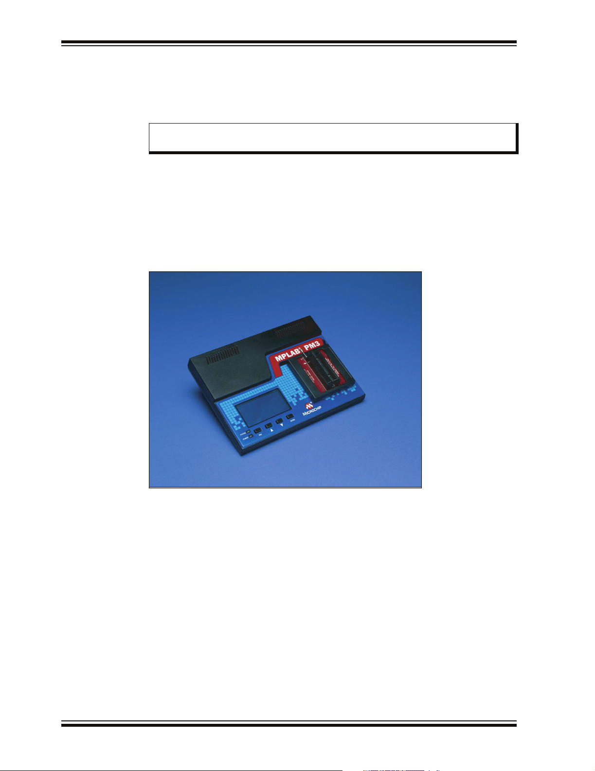
1.4 MPLAB PM3 SYSTEM COMPONENTS
The MPLAB PM3 device programmer system consists of the following:
• MPLAB PM3 device programmer (see Figure 1-1)
• Module sockets
Note: A complete line of socket modules is available. The socket modules may
be ordered separately for the devices that will be programmed.
• RS-232 Interface cable to connect to any standard PC serial port
• USB Interface cable to connect to any standard PC USB port
•ICSP cable
• Power supply
• MPLAB IDE software – an Integrated Development Environment including a text
editor, project manager and simulator for debugging. Also included are the
MPASM assembler, MPLINK object linker and MPLIB object librarian.
FIGURE 1-1: MPLAB
1.5 MPLAB PM3 CE COMPLIANCE
The MPLAB PM3 device programmer is designed, tested and certified to meet the
Electromagnetic Compatibility requirements known as the CE compliance directives.
These standards, set by the European Union (EU) countries, include limiting radiated
emission, reducing susceptibility to radiated emission and reducing susceptibility to
Electrostatic Discharge (ESD).
®
PM3 DEVICE PROGRAMMER
DS51464C-page 8 © 2006 Microchip Technology Inc.
Page 15

MPLAB PM3 Overview
1.6 HOW MPLAB PM3 HELPS YOU
With the MPLAB PM3 device programmer, you can program Microchip devices from a
PC Host, or you can use the device programmer as a stand-alone unit.
• MPLAB PM3 is easy to use and flexible in programming Microchip devices and
package types.
• MPLAB PM3 will expand to support future Microchip devices always providing the
latest programming algorithms to support Microchip PIC
and other Microchip parts, via the Microchip web site (http://www.microchip.com).
• With an optional MPLAB PM3 Card inserted, you can store and transport device
settings for programming.
1.7 MPLAB PM3 OPERATING WITH A PC
Using MPLAB Integrated Development System (IDE) as the interface, MPLAB PM3
becomes another tool in MPLAB IDE, allowing you to quickly compile, test and debug
your firmware, then download it into MPLAB PM3 to be programmed into your device.
1.8 MPLAB PM3 OPERATING WITHOUT A PC (STAND-ALONE)
Without a PC connection to MPLAB PM3, the unit operates as a stand-alone device
programmer. However, a PC connection is required for operating system updates. The
main programmer features of MPLAB PM3 are available, including Read, Program and
Verify.
®
microcontroller devices
1.9 MPLAB INTEGRATED DEVELOPMENT ENVIRONMENT
The MPLAB IDE desktop provides an environment for developing and debugging your
application. MPLAB PM3 is integrated into MPLAB IDE, but you do not need
MPLAB IDE to use MPLAB PM3.
This document covers the basic setup and operation of the MPLAB PM3 device
programmer, but it does not cover all functions of MPLAB IDE. Read the MPLAB IDE
documentation to get a full understanding of the features and debug capabilities of
MPLAB IDE.
© 2006 Microchip Technology Inc. DS51464C-page 9
Page 16

MPLAB® PM3 User’s Guide
1.10 MPLAB DEVELOPMENT TOOLS
MPLAB IDE integrates several tools to provide a complete development environment.
• MPLAB Project Manager
The Project Manager is used to create a project and work with the specific files
related to the project. When using a project, source code is rebuilt and
downloaded to the simulator or emulator with a single mouse click.
• MPLAB Editor
The MPLAB Editor is used to create and edit text files such as source files, code
and linker script files.
• MPLAB SIM Simulator
The software simulator models the instruction execution and I/O of the PICmicro
MCUs.
• MPLAB ICE Emulator
The MPLAB ICE emulator uses hardware to emulate PICmicro MCUs in real time,
either with or without a target system.
• MPASM Universal Assembler/MPLINK Relocatable Linker/MPLIB Librarian
The MPASM assembler allows source code to be assembled without leaving
MPLAB IDE. MPLINK linker creates the final application by linking relocatable
modules from MPASM assembler, MPLAB C17 and MPLAB C18. MPLIB librarian
manages custom libraries for maximum code reuse.
• MPLAB C18 and MPLAB C30 C Compilers
The MPLAB C18 and MPLAB C30 C Compilers provide ANSI-based high-level
source code solutions. Complex projects can use a combination of C and
assembly source files to obtain the maximum benefits of speed and
maintainability.
• MPLAB PM3, PRO MATE II and PICSTART Plus Programmers
Develop code with the simulator or an emulator, assemble or compile it, then use
one of these tools to program devices. This can all be accomplished with
MPLAB IDE.
• Third Party Tools
Many other companies have development tools for Microchip products that work
with MPLAB IDE. Consult the Microchip web site for additional information.
DS51464C-page 10 © 2006 Microchip Technology Inc.
Page 17
Chapter 2. Installing MPLAB PM3
2.1 INTRODUCTION
This chapter describes how to install MPLAB PM3 hardware and software. Topics
covered in this chapter include:
• Installing MPLAB PM3 Software
• Installing MPLAB PM3 Hardware
• Powering Up MPLAB PM3
• Configuring MPLAB IDE for Use with MPLAB PM3
2.2 INSTALLING MPLAB PM3 SOFTWARE
MPLAB PM3 hardware requires the following software support if you are using a PC
running Windows:
• MPLAB IDE software
Note: There are alternative command-line programs for MPLAB PM3 control,
also installed with MPLAB IDE, named PM3CMD and Visual PROCMD.
MPLAB® PM3
USER’S GUIDE
• USB communications driver
2.2.1 MPLAB IDE Software Installation
The MPLAB IDE software should be installed by following the instructions in the
“MPLAB
discussed next.
• For a CD-ROM:
• For the Microchip Website:
®
IDE Quick Start Guide” (DS51281). A brief summary of this procedure is
- Insert the MPLAB IDE CD into the CD-ROM drive.
- Follow the on-screen instructions to install the MPLAB IDE software.
- Go to www.microchip.com and follow the links to the Development Tools
page.
- Click the links to the latest MPLAB IDE release and download.
© 2006 Microchip Technology Inc. DS51464C-page 11
Page 18
MPLAB® PM3 User’s Guide
2.2.2 USB Driver Installation
Do not allow the Windows OS to pick a USB driver. MPLAB PM3 will not work with
this driver. You must follow the procedure specified at MPLAB IDE software installation to set up the USB driver or to fix an improper driver installation.
Install MPLAB IDE first. The USB driver installation instructions will pop up at the end
of MPLAB IDE installation. Follow those instructions to install the USB driver.
The instructions are in the MPLAB IDE installation directory under:
MPLAB PM3\Drivers\instr.htm
where instr.htm depends on your Personal Computer (PC) OS:
• ddpm398.htm – Windows 98
• ddpm3me.htm – Windows ME
• ddpm3.htm – Windows 2000/XP
2.3 INSTALLING MPLAB PM3 HARDWARE
IMPORTANT: Do not allow the Windows OS to pick a USB driver. Follow the procedure
specified in Section 2.2.2 “USB Driver Installation”.
The MPLAB PM3 hardware is simple to set up:
• If you are using MPLAB IDE:
- Attach the communications cable.
- Connect the power supply to MPLAB PM3.
- Install the socket module (or attach the ICSP cable).
• If you are using MPLAB PM3 in Stand-Alone mode:
- Connect the power supply to MPLAB PM3.
- Install the socket module or attach the ICSP cable.
• If you are using the MPLAB PM3 Card in MPLAB PM3:
- Insert the MPLAB PM3 Card into the SD-MMC port on the back of the
programmer.
NOTICE
2.3.1 Installing the Communications Cable
MPLAB PM3 provides communications with the host PC via an RS-232 9-pin D type
connector or a USB connector. See Figure 2-1 for communication port locations.
MPLAB PM3 is supplied with two 6-foot data cables: one with DB-9 connectors and one
with USB connectors. All lines on the serial cable are wired straight through. The serial
cable is NOT a null modem cable.
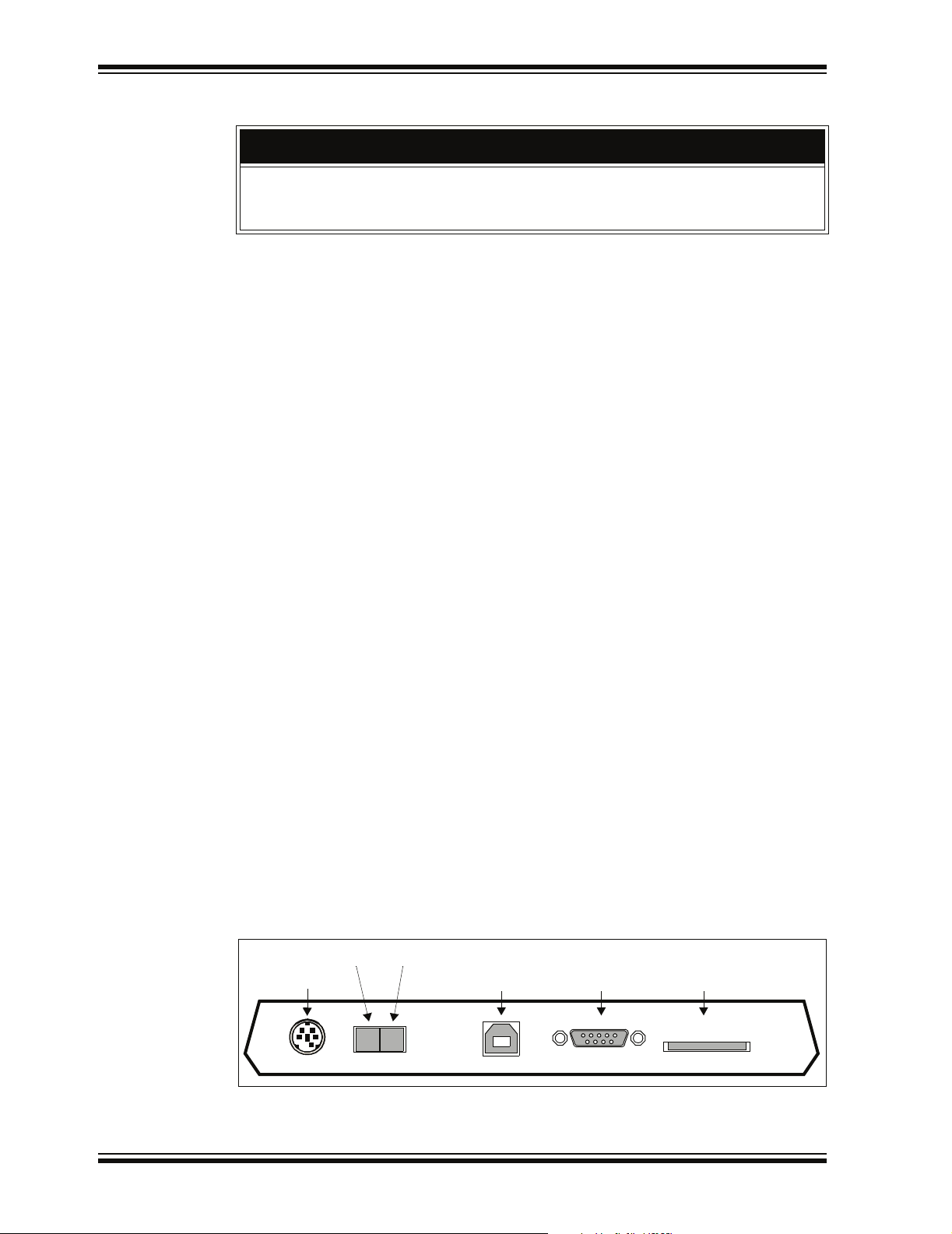
FIGURE 2-1: BACK VIEW OF MPLAB
Power On
Power Input
PWR
DS51464C-page 12 © 2006 Microchip Technology Inc.
Power Off
USB Port
I
O
USB
®
RS-232
PM3
Serial Port
Secure Digital/
Multi-Media Card Port
SD-MMC
Page 19

Installing MPLAB PM3
2.3.1.1 FOR USB COMMUNICATIONS
• Connect one end of the USB cable to a USB port on your PC.
• Connect the cable from the PC USB port to the corresponding USB connector on
the back of MPLAB PM3.
Note: If you are using USB and a “New Hardware Detected” notice appears on
your PC, you must follow the directions on installing the proper driver or
your MPLAB PM3 will not work.
2.3.1.2 FOR RS-232 COMMUNICATIONS
NOTICE
IMPORTANT: Set the COM port FIFO buffers off, the Flow Control to “Hardware” and
Baud Rate to 57600. You will need to reboot your PC for these settings to take effect.
See Section B.5.2.5 “Manually Setting Up The Port” for more information.
• Connect one end of the RS-232 cable to an available COM port on your PC.
Check your PC setup to see which communications port is available.
• Connect the cable from the PC COM port to corresponding RS-232 connector on
the back of MPLAB PM3. For more on serial connections, see
Section A.2 “Connecting to a PC via the Serial Port”.
2.3.2 Installing the Power Supply
MPLAB PM3 comes with a proprietary external power supply.
1. Make sure that the power switch on the back of the unit is in the OFF position
(see Figure 2-1).
2. Plug the power supply into a power socket and connect the power supply cable
to the unit.
© 2006 Microchip Technology Inc. DS51464C-page 13
Page 20
MPLAB® PM3 User’s Guide
2.3.3 Installing a Socket Module or ICSP Cable
Socket modules are sold separately. MPLAB PM3 comes with an 18-inch ICSP cable
for ICSP programming. See Figure 2-2 for location of socket module connectors and
ICSP connector.
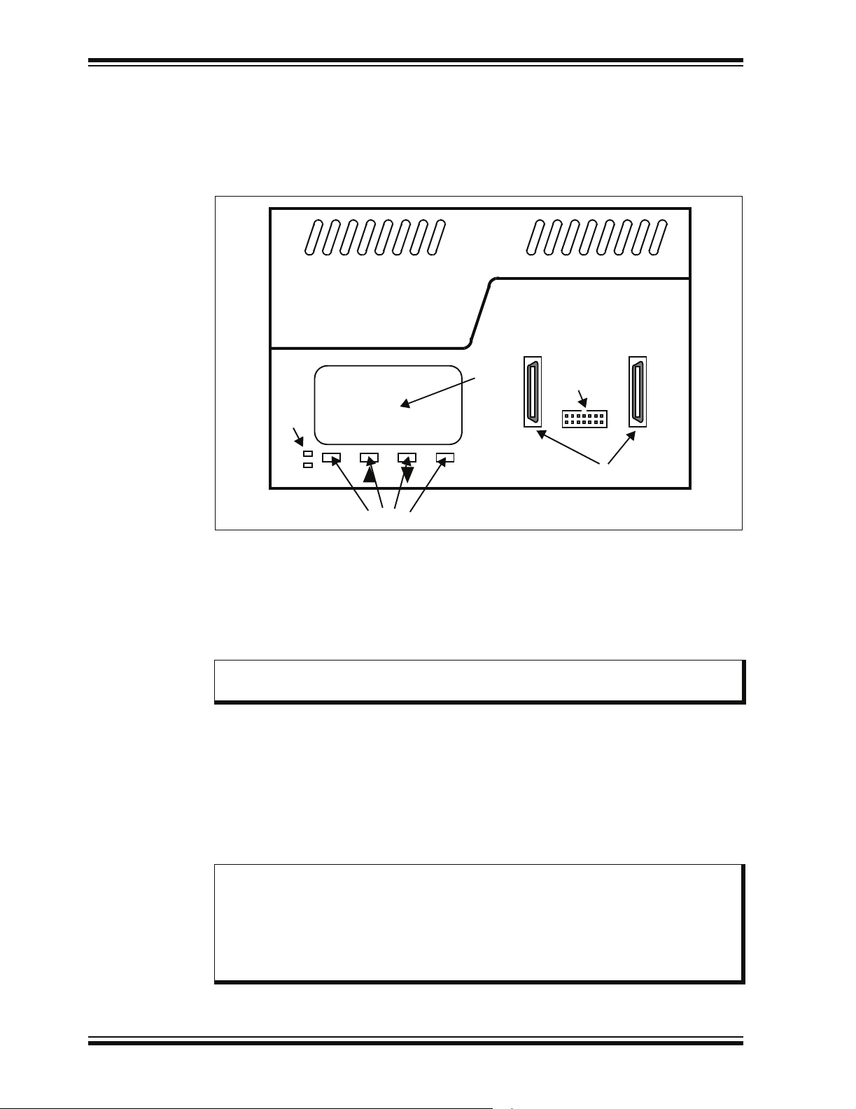
FIGURE 2-2: TOP VIEW OF MPLAB
®
PM3
MPLAB® PM3
Device Programmer
LCD
LEDs
STATUS
POWER
ESC ENTER
Keys/Buttons
M
2.3.3.1 SOCKET MODULE INSTALLATION
Socket modules are available to accommodate each device package. The “Product
Selector Guide” (DS00148) lists Microchip’s devices, tools and socket modules. The
“Development System Ordering Guide” (DS30177) describes the available socket
modules. Also, the Readme for MPLAB PM3 file lists socket module support for each
device.
ICSP Connector
Socket Module Connectors
Note: MPLAB PM3 allows hot swapping of socket modules. If the status LED is
not lit, sockets can be replaced.
2.3.3.1.1 For MPLAB PM3 Socket Modules
1. Align the connectors on the socket module with the connectors on MPLAB PM3
(Figure 2-2).
2. Push the socket module down evenly mating the connectors.
It is always a good practice to insert a known blank device and do a Blank Check
whenever the socket module is changed.
2.3.3.1.2 For PRO MATE II Socket Modules
Note 1: In order to use PRO MATE II socket modules with MPLAB PM3, you must
obtain an AC164350 adapter kit. See the “Development System Ordering
Guide” (DS30177).
2: The PRO MATE II ICSP socket module is not supported by MPLAB PM3.
An 18-inch ICSP cable is included with MPLAB PM3, eliminating the
need for an ICSP socket.
DS51464C-page 14 © 2006 Microchip Technology Inc.
Page 21

Installing MPLAB PM3
1. Align the connectors on the adapter with the connectors on MPLAB PM3.
2. Push the adapter down evenly mating the connectors.
3. Align the socket module with the adapter on MPLAB PM3.
4. Tighten the two socket module thumb screws evenly and simultaneously. Avoid
over tightening; they should be finger-tight only.
Note: The gold connector strips on the PRO MATE II socket module are relatively
fragile. Avoid touching them with the socket module screws and avoid
over-tightening the screws.
It is always a good practice to insert a known blank device and do a Blank Check
whenever the socket module it changed.
2.3.3.2 ICSP CABLE INSTALLATION
1. Connect the ICSP cable connector to the ICSP socket on MPLAB PM3
(Figure 2-2).
2. Leave the individual leads unconnected at this time.
2.3.3.3 MPLAB PM3 CARD INSERTION
1. Align the MPLAB PM3 Card with the SD-MMC slot on the back of the
MPLAB PM3 programmer, and insert the notched corner end of the card into the
slot. The card is keyed so that it only goes in one way.
2. Push the card into the slot.
3. To remove the card, push in to eject.
2.4 POWERING UP MPLAB PM3
Once you have connected the hardware and installed the software, you are ready to
turn on MPLAB PM3. Turn the power switch on the side of MPLAB PM3 to l (ON)
(refer back to Figure 2-1).
Note: MPLAB PM3 automatically performs a self-test ensuring the programmer is
functional. No calibration is required.
If any portion of the self-test fails, MPLAB PM3 will display the corrective course of
action on the LCD panel. For normal start-up, the MPLAB PM3 will beep once. See
Section B.7 “Error Messages – LCD” for information on beep codes and LCD error
messages. MPLAB IDE will provide further information to help you debug the issue.
On a successful power-up, you should see the following types of messages appear on
the LCD panel on the front of MPLAB PM3:
• MPLAB PM3 splash screen
• Version numbers and copyright dates
• MPLAB PM3 menu
At this point, you are ready to use MPLAB PM3. If you are going to use MPLAB PM3
with MPLAB IDE (Windows), please refer to Chapter 4. “Using MPLAB PM3 with
MPLAB IDE”. If you are going to use MPLAB PM3 in Stand-Alone mode, please refer
to Chapter 5. “Using MPLAB PM3 in Stand-Alone Mode”. If you are using the
MPLAB PM3 Card with either MPLAB IDE or in Stand-Alone mode, also refer to
Chapter 6. “Using the MPLAB PM3 Card”
© 2006 Microchip Technology Inc. DS51464C-page 15
Page 22
MPLAB® PM3 User’s Guide
2.4.1 Indicator Lights and Buzzer
Two indicator lights (LEDs) are located on the front of the programmer. A buzzer, for
audio indication, is incorporated into the programmer as well.
TABLE 2-1: STATUS LED INDICATIONS
LED Condition
Red Booting up, Programming Failed, Other Error
Orange Working/Busy
Green Programming Passed
TABLE 2-2: POWER LED
LED Condition
On Programmer powered
Off Programmer not powered
2.4.2 Powering Down MPLAB PM3
Turn the power switch on the back of MPLAB PM3 to “OFF”.
2.5 CONFIGURING MPLAB IDE FOR USE WITH MPLAB PM3
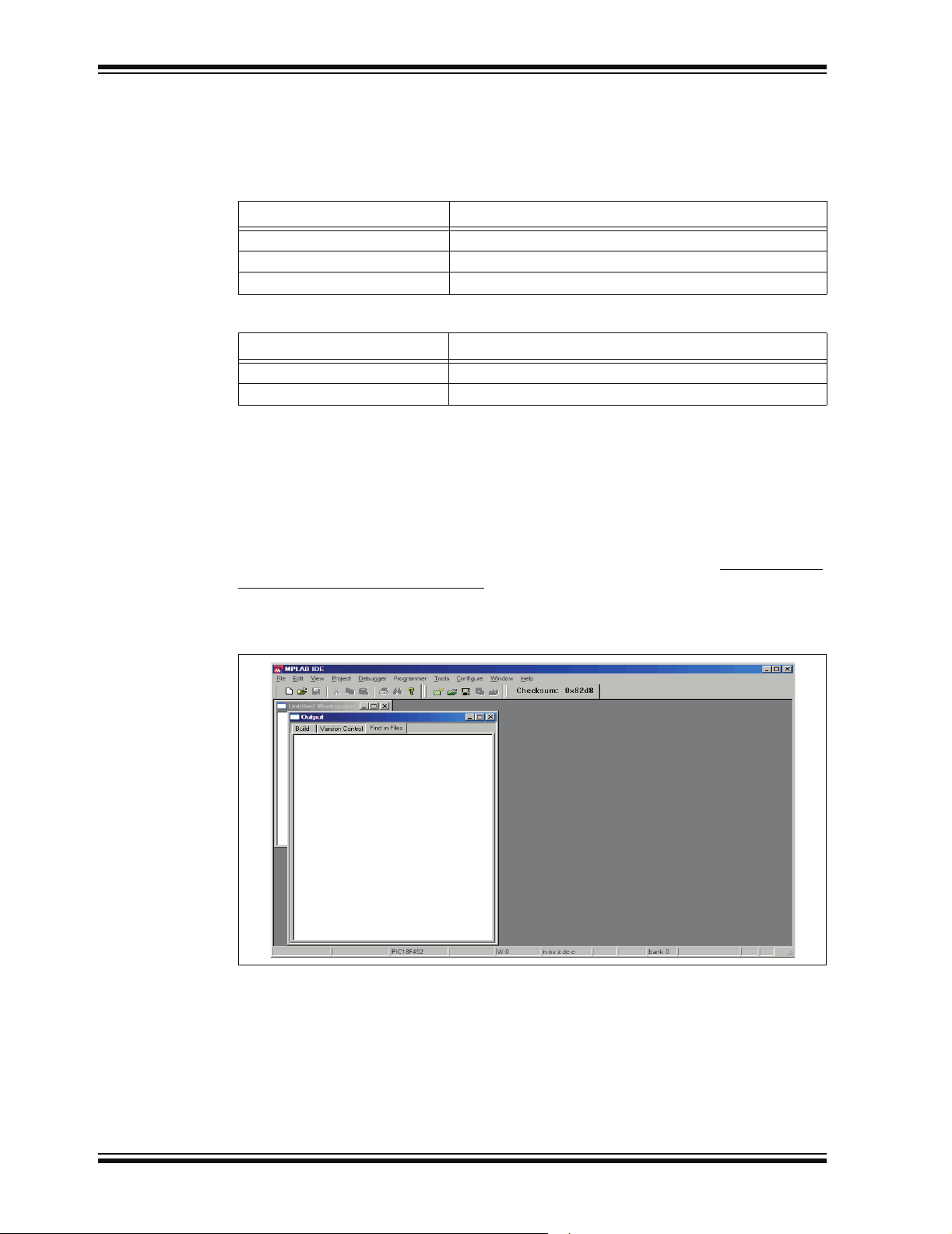
2.5.1 Starting MPLAB IDE
Once MPLAB IDE is installed on your PC, from the Start menu, select All Programs>
Microchip MPLAB IDE>MPLAB IDE.
The MPLAB IDE desktop should look similar to Figure 2-3.
FIGURE 2-3: MPLAB
®
IDE DESKTOP
DS51464C-page 16 © 2006 Microchip Technology Inc.
Page 23
Installing MPLAB PM3
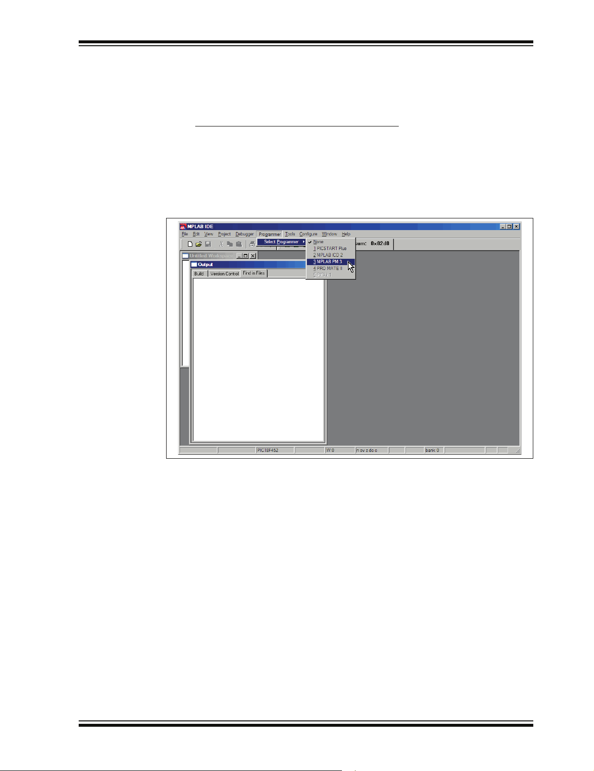
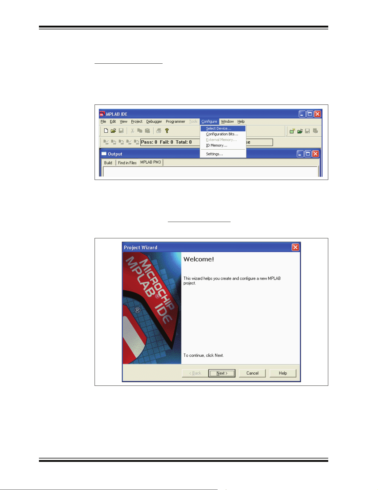
2.5.2 Selecting MPLAB PM3 as the Programmer
In addition to MPLAB PM3, the PRO MATE II and PICSTART Plus device programmers
are supported under MPLAB IDE. However, only one programmer can be used at a
time.
Select Programmer>Select Programmer>MPLAB PM3
list of available programmers (Figure 2-4). After MPLAB PM3 is selected:
• The Programmer menu changes to include the MPLAB PM3 Programmer Menu
and Settings.
• The MPLAB PM3 Toolbar is revealed.
• The name of the programmer appears on the status bar.
FIGURE 2-4: SELECT PROGRAMMER MENU
to select MPLAB PM3 from the
© 2006 Microchip Technology Inc. DS51464C-page 17
Page 24
MPLAB® PM3 User’s Guide
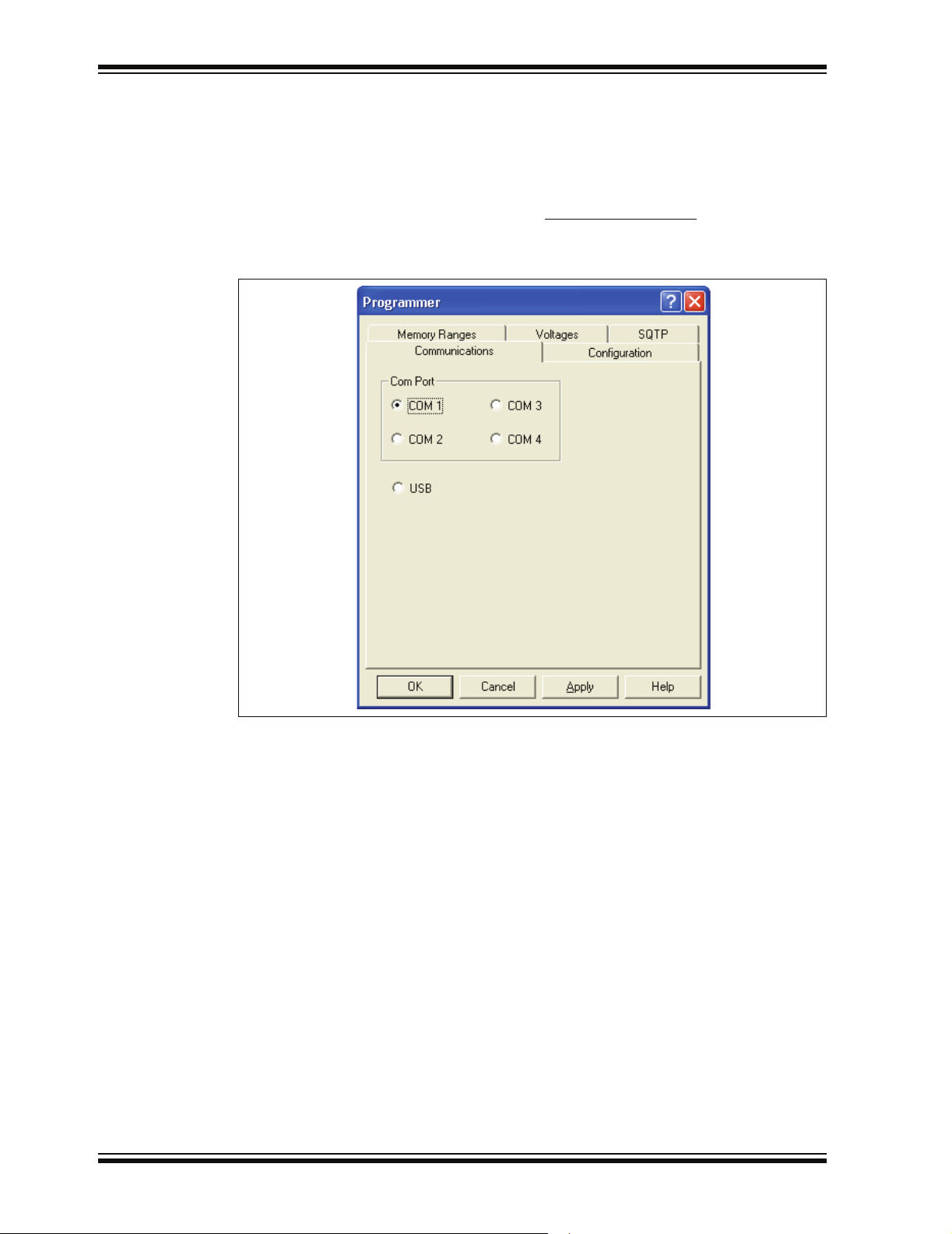
2.5.3 Setting Up the Communications Port
You can set up MPLAB PM3 to communicate with MPLAB IDE through one of the serial
COM ports (1-4) or USB.
2.5.3.1 SERIAL COMMUNICATIONS
From the MPLAB Programmer menu, select Programmer>Settings
Communications tab. A dialog similar to the one shown in Figure 2-5 will display.
FIGURE 2-5: COMMUNICATIONS PORT SETUP DIALOG
and click on the
The Communications Port Setup dialog shows the possible PC serial and USB
communication ports. Click OK to set the options or Cancel to ignore the changes and
close the dialog.
DS51464C-page 18 © 2006 Microchip Technology Inc.
Page 25
Installing MPLAB PM3
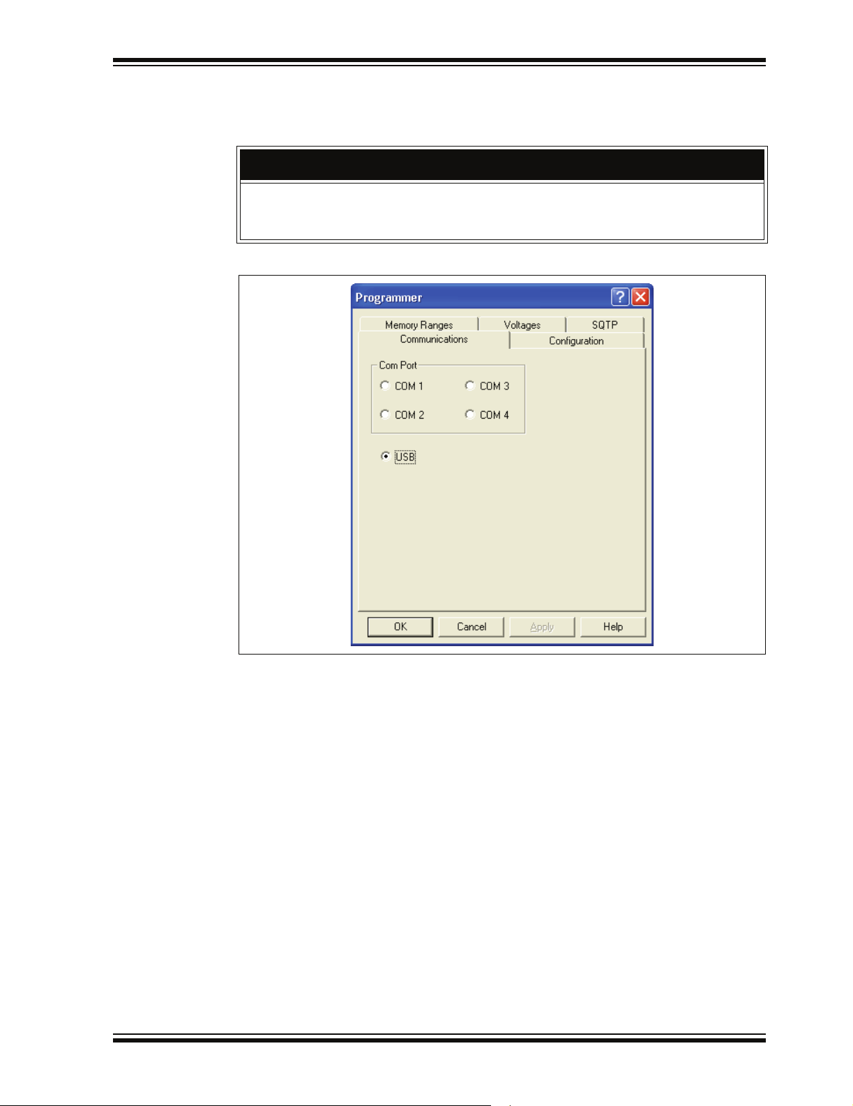
2.5.3.2 USB COMMUNICATIONS
To use USB communications between the PC and the MPLAB PM3 device
programmer, select the
Do not allow the Windows OS to pick a USB driver; it will not work and you will then
not be able to install the proper driver. Follow the procedure specified in
Section 2.2 “Installing MPLAB PM3 Software”.
FIGURE 2-6: USB PORT
USB port (Figure 2-6). Click OK.
CAUTION
To make sure the port is set up properly, follow the instructions in the “For USB
Communications” subsection in Section 2.3.1 “Installing the Communications
Cable”.
© 2006 Microchip Technology Inc. DS51464C-page 19
Page 26
MPLAB® PM3 User’s Guide
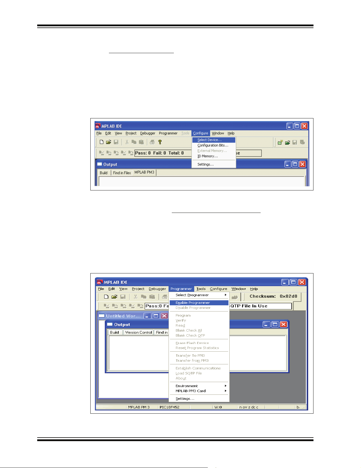
2.5.4 Selecting a Device in MPLAB IDE
Chose Configure>Select Device to select the device you wish to program from the list
of available devices (Figure 2-7). When you select a device, indicators next to the
Microchip Tools names show the level of support for that device:
• Green – supports the device
• Yellow – limited (advance) support
• Red – no support.
If the selected device is supported by MPLAB PM3, click OK.
FIGURE 2-7: SELECT DEVICE DIALOG
2.5.5 Enabling MPLAB PM3
To enable MPLAB PM3, select Programmer>Enable Programmer (Figure 2-8). The
MPLAB PM3 toolbar will appear when the programmer is enabled. See Chapter
7. “MPLAB PM3 – MPLAB IDE Reference” for more reference information on the
MPLAB PM3 programmer. The MPLAB PM3 Card is available from the Programmer
menu only if you have the MPLAB PM3 Card inserted in the MPLAB PM3 programmer.
MPLAB IDE may warn you that your programmer OS Suite is out of date. If you choose,
MPLAB IDE will automatically update the necessary files at these warnings.
FIGURE 2-8: ENABLE PROGRAMMER
DS51464C-page 20 © 2006 Microchip Technology Inc.
Page 27
Installing MPLAB PM3
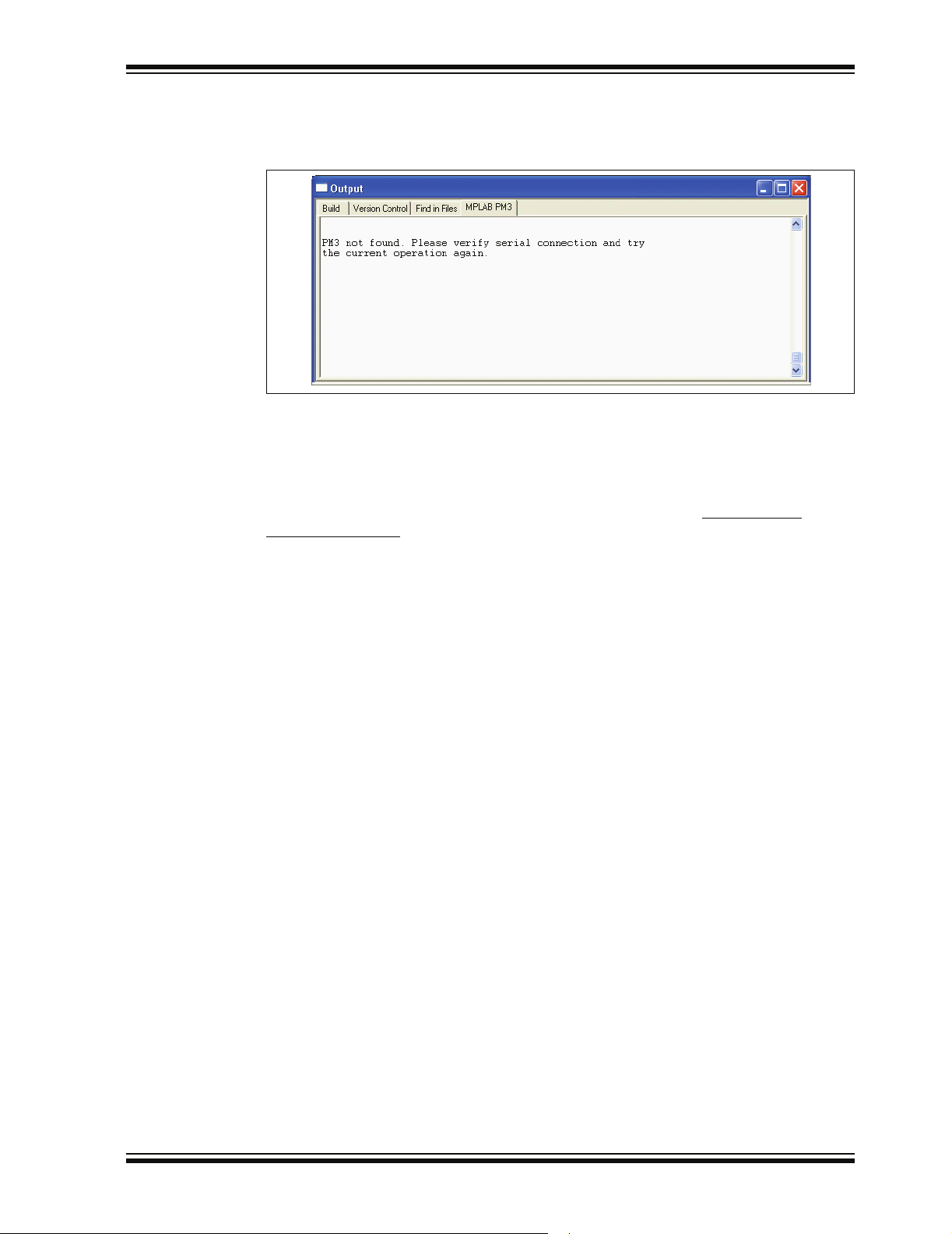
If MPLAB PM3 is not found on the selected port, the Communications Error dialog
(Figure 2-9) will appear.
FIGURE 2-9: COMMUNICATIONS ERROR DIALOG
If you cannot establish communications between the PC and MPLAB PM3, please
make sure you have installed the hardware and software correctly. If you still cannot
establish communications between the PC and MPLAB PM3, refer to Appendix
B. “Troubleshooting”.
If you have been using another programmer (e.g., PICSTART Plus), the MPLAB PM3
menu may be unavailable. From the Programmer menu, select Programmer>
Select Programmer to bring up the Select Programmer dialog and choose MPLAB PM3
from the list. The MPLAB PM3 menu will appear on the menu bar.
2.5.6 Inserting a Device into MPLAB PM3
If you are using a socket module, insert the device to be programmed into the MPLAB
PM3 socket. Position pin one to be top justified in the socket. Secure the device by
pushing down the silver lever on the socket or closing the clamshell.
© 2006 Microchip Technology Inc. DS51464C-page 21
Page 28

MPLAB® PM3 User’s Guide
NOTES:
DS51464C-page 22 © 2006 Microchip Technology Inc.
Page 29

3.1 INTRODUCTION
The tutorial in this chapter leads you through the steps involved in programming the
PIC18F452 PICmicro device using MPLAB IDE Project Wizard.
3.2 BEFORE YOU BEGIN
Before you can begin this tutorial, you must:
1. Install the MPLAB IDE software. See Section 2.2 “Installing MPLAB PM3
Software”.
2. Install the MPLAB PM3 hardware. See Section 2.3 “Installing MPLAB PM3
Hardware”.
3. Make sure you have read and completed all the instructions in
Section 2.4 “Powering Up MPLAB PM3” and Section 2.5 “Configuring
MPLAB IDE for Use with MPLAB PM3”.
4. Make sure that your PC and MPLAB PM3 are communicating and the
MPLAB PM3 menu appears on the MPLAB IDE menu before you begin this
tutorial.
MPLAB® PM3
USER’S GUIDE
Chapter 3. Tutorial
3.3 PROGRAMMING OVERVIEW
Programming a device involves the following steps:
• Selecting the Device
• Creating the Project
• Setting Up Language Tools
• Naming the Project
• Adding Files to the Project
• Building the Initial Project
• Creating Code
• Building the Project
• Enabling MPLAB PM3
• Programming the Device
• Verifying the Programming
© 2006 Microchip Technology Inc. DS51464C-page 23
Page 30
MPLAB® PM3 User’s Guide
3.4 SELECTING THE DEVICE
If you have not already selected the device in MPLAB IDE, do so by selecting
Configure>Select Device
PIC18F452 device.
Under Microchip Programmer Tool Support, verify that this device is supported (green
light) by MPLAB PM3. Click OK.
FIGURE 3-1: SELECTING THE DEVICE
3.5 CREATING THE PROJECT
to open the Select Device dialog (Figure 3-1) and select the
In order to program the device, you’ll need a hex file. In this example, we’ll create a
project using the Project Wizard. We will use a single assembly file for this project and
a linker script. Choose the Project>Project Wizard
FIGURE 3-2: PROJECT WIZARD WELCOME SCREEN
.
Click on Next> to advance to the next dialog in the Project Wizard.
DS51464C-page 24 © 2006 Microchip Technology Inc.
Page 31

Tutorial
The next dialog allows you to select the device, which we’ve already done. Make sure
that it says PIC18F452. If it does not, select the PIC18F452 from the drop down menu.
Click Next>.
FIGURE 3-3: PROJECT WIZARD – SELECT DEVICE
© 2006 Microchip Technology Inc. DS51464C-page 25
Page 32

MPLAB® PM3 User’s Guide
3.6 SETTING UP LANGUAGE TOOLS
Step Two of the Project Wizard sets up the language tools that are used with this
project. Select “Microchip MPASM Toolsuite” in the Active Toolsuite list box. Then
“MPASM” and “MPLINK” should be visible in the Toolsuite Contents box. Click on each
one to see its location. If MPLAB IDE was installed into the default directory, the
MPASM assembler executable will be:
C:\Program Files\Microchip\MPASM Suite\MPAsmWin.exe
and the MPLINK linker executable will be:
C:\Program Files\Microchip\MPASM Suite\MPLink.exe
If these do not show up correctly, use the Browse button to set them to the proper files
in the MPLAB IDE subfolders.
FIGURE 3-4: PROJECT WIZARD – SELECT LANGUAGE TOOLS
When you are finished, click Next>.
DS51464C-page 26 © 2006 Microchip Technology Inc.
Page 33

3.7 NAMING THE PROJECT
Step Three of the wizard allows you to name the project and put it into a folder. This
sample project will be called 18F452Proj. Using the Browse button, place the project
in a folder on the C drive named My Projects. Click Next>.
FIGURE 3-5: PROJECT WIZARD – NAME PROJECT
Tutorial
© 2006 Microchip Technology Inc. DS51464C-page 27
Page 34

MPLAB® PM3 User’s Guide
3.8 ADDING FILES TO THE PROJECT
Step Four of the Project Wizard allows file selection for the project. A source file has
not yet been selected, so we will use an MPLAB IDE template file. The template files
are simple files that can be used to start a project. They have the essential sections for
any source file, and contain information that will help you write and organize your code.
These files are in the MPLAB IDE folder, which by default is in the Program Files
folder on the PC. There is one template file for each Microchip PICmicro MCU and
®
dsPIC
Scroll to the Program Files folder on Drive C:, open it, and scroll down to the
Microchip folder. Open the Microchip folder and scroll down to the MPASM Suite
directory. Open the MPASM Suite directory and get a template from the Object folder
in the Template folder, and choose the file named f452tmpo.asm.
If MPLAB IDE is installed in the default location, the full path to the file will be:
C:\Program Files\Microchip\MPASM Suite\TEMPLATE\Object\f452tmpo.asm
FIGURE 3-6: PROJECT WIZARD – SELECT TEMPLATE FILE
DSC device.
Press Add>> to move the file name to the right panel, and click on the check box at the
start of the line with the file name to enable this file to be copied to our project directory.
DS51464C-page 28 © 2006 Microchip Technology Inc.
Page 35

Tutorial
Next, add the second file for our project, the linker script. There is a linker script for each
device. These files define the memory configuration and register names for the various
parts. The linker scripts are in the folder named LKR under the MPASM Suite folder.
Use the file named 18F452.lkr The full path is:
C:\Program Files\Microchip\MPASM Suite\LKR\18F452.lkr
To copy this linker script into our project, click on the check box.
FIGURE 3-7: PROJECT WIZARD – SELECT LINKER SCRIPT
Make sure that your dialog looks like the picture above, with both check boxes
checked, then press Next> to finish the Project Wizard.
The final screen of the Project Wizard is a summary showing the selected device, the
toolsuite and the new project file name.
FIGURE 3-8: PROJECT WIZARD – SUMMARY
© 2006 Microchip Technology Inc. DS51464C-page 29
Page 36

MPLAB® PM3 User’s Guide
After pressing the Finish button, review the Project window on the MPLAB IDE
desktop. It should look like Figure 3-9. If the Project window is not open, select
View>Project
FIGURE 3-9: PROJECT WINDOW
.
3.9 BUILDING THE INITIAL PROJECT
From the Project menu, we can assemble and link the current files. They don’t have
any of our code in them yet, but this ensures that the project is set up correctly.
Click back on the 18f452Proj.mcw window to make it the active window. Now, build the
project by selecting Project>Build All
process as shown in Figure 3-10.
FIGURE 3-10: INITIAL BUILD RESULTS WINDOW
. The Output window shows the result of the build
DS51464C-page 30 © 2006 Microchip Technology Inc.
Page 37

3.10 CREATING CODE
Open the template file in the project by double clicking on its name in the Project
window (see Figure 3-11).
The file has some comments at the beginning, and this area can be used as a standard
comment information header for the file. For now, you’ll leave this as it is, but if this were
a real project, you could put information about your design here.
FIGURE 3-11: TEMPLATE FILE
Tutorial
Scroll down to the bottom of the file.
The code in the first part of the file is for more advanced functions such as setting up
interrupts and Configuration bits in a final application. These details can be ignored at
this point with focus on writing the code. The new code will be placed in the file at the
point after the symbol Main is defined.
FIGURE 3-12: TEMPLATE FILE – MAIN
© 2006 Microchip Technology Inc. DS51464C-page 31
Page 38

MPLAB® PM3 User’s Guide
When any source file is opened, you are automatically in the editor. Type in this code:
Main:
clr f WREG
movwf PORTC; clear PORTC
movwf TRISC; configure PORTC as all outputs
Init
clrf COUNT
IncCount
incf COUNT
movf COUNT,W
movwf PORTC; display COUNT on PORTC
callDelay
goto IncCount; infinite loop
Delay
movlw 0x40; set outer delay loop
movwf DVAR2
Delay0
movlw 0xFF
movwf DVAR; set inner delay loop
Delay1
decfsz DVAR
goto Delay1
decfsz DVAR2
goto Delay0
return
The template file should now look like Figure 3-13.
FIGURE 3-13: TEMPLATE FILE – ADD CODE
DS51464C-page 32 © 2006 Microchip Technology Inc.
Page 39

Tutorial
In this bit of code, we used three variables named COUNT, DVAR and DVAR2. These
variables need to be defined in the template file in the UDATA section for uninitialized
data. There are already three variables in this section of the template file, ours can be
added at the end using the same format. Each variable is an 8-bit variable, so they only
need to reserve 1 byte each.
FIGURE 3-14: TEMPLATE FILE – ADD VARIABLES
Add
these
three
lines
© 2006 Microchip Technology Inc. DS51464C-page 33
Page 40

MPLAB® PM3 User’s Guide
3.11 BUILDING THE PROJECT
Select Project>Build All to assemble and link the code. If the code assembled with no
errors, the Output window will look like Figure 3-15.
FIGURE 3-15: BUILD OUTPUT WINDOW
Save your project by selecting File>Save Workspace
If these do not assemble and link successfully, check the following items and then build
the project again:
• Check the spelling and format of the code entered in the Editor window. Make
sure the new variables and the special function registers, TRISC and PORTC, are
in upper case. If the assembler reported errors in the Output window, double click
on the error and MPLAB IDE will open the corresponding line in the source code
with a green arrow in the left margin of the source code window.
• Check that the correct assembler (MPASM assembler) and linker for PICmicro
MCU devices is being used. Select Project>Set Language Tool Locations
on the plus boxes to expand the Microchip MPASM assembler toolsuite and its
executables. Click MPASM Assembler (mpasmwin.exe) and review their location
in the display. If the location is correct, click Cancel. If it is not, change it and then
click OK. The default search paths can be empty.
Upon a successful build, the output file generated by the language tool will be loaded.
This file contains the object code that can be programmed into a PICmicro MCU and
debugging information so that source code can be debugged, and source variables can
be viewed symbolically in Watch windows.
Now that you’ve built your project successfully, you can prepare for programming your
device.
.
. Click
DS51464C-page 34 © 2006 Microchip Technology Inc.
Page 41

3.12 ENABLING MPLAB PM3
If you haven’t already started the MPLAB PM3 device programmer, select
Programmer>Enable Programmer
programmer is enabled.
Select View>Program Memory
(see Figure 3-16) to view the hex code you’ve just built. You can resize or move the
Program Memory window on your display. You may wish to close the Build Results
window.
FIGURE 3-16: VIEWING PROGRAM MEMORY
Tutorial
. The MPLAB PM3 toolbar will appear when the
and click on Opcode Hex at the bottom of the window
© 2006 Microchip Technology Inc. DS51464C-page 35
Page 42

MPLAB® PM3 User’s Guide
3.13 PROGRAMMING THE DEVICE
Now that you have your data in program memory, you can program the device. Make
sure your PIC18F452 device is inserted in the appropriate socket on MPLAB PM3.
Then, select Programmer>Program
and, when finished, the Output window will display the results (see Figure 3-17).
FIGURE 3-17: PROGRAMMING RESULTS
. The MPLAB IDE window will indicate the progress
3.14 VERIFYING THE PROGRAMMING
Select Programmer>Verify to double-check the programming in the device. If any
address locations on the device do not match program memory, an error log will display
the discrepancies. If the bad data in the error log is 0000, try reseating the socket
module.
3.15 TUTORIAL SUMMARY
By completing this tutorial, you have performed the major steps for creating, building
and programming a simple project. Tasks completed include:
Selecting the device – the PIC18F452.
Using the Project Wizard to create a project, and using the wizard to:
• select MPLAB IDE built in MPASM assembler and MPLINK linker language tools,
• add files for the project: a template file for the device selected, and a linker script
to build it properly.
Writing some simple code to send a changing value out an I/O port.
Building the project.
And finally, programming the PIC18F452 device.
These are the essential steps for programming a device with MPLAB IDE and
MPLAB PM3.
DS51464C-page 36 © 2006 Microchip Technology Inc.
Page 43

Chapter 4. Using MPLAB PM3 with MPLAB IDE
4.1 INTRODUCTION
This chapter describes the main steps in programming and reading a device using the
MPLAB PM3 device programmer. Topics covered in this chapter include:
• Before You Begin
• MPLAB PM3 Dialogs
• Setup for Programming a Device
• Programming a Device
• Verifying the Programming
• Reading a Device
• Special Programming
4.2 BEFORE YOU BEGIN
Before using MPLAB PM3, you must have performed the following initialization steps:
1. Installed the MPLAB IDE software (Section 2.2 “Installing MPLAB PM3
Software”) and MPLAB PM3 hardware (Section 2.3 “Installing MPLAB PM3
Hardware”).
2. Turned the power on MPLAB PM3 (Section 2.4 “Powering Up MPLAB PM3”).
3. Selected MPLAB PM3 as your programmer (Section 2.5.2 “Selecting MPLAB
PM3 as the Programmer”).
4. Configured the communications port that MPLAB IDE will use to communicate
with MPLAB PM3 (Section 2.5.3 “Setting Up the Communications Port”).
5. Selected the device you wish to program from the list of available devices
(Section 2.5.4 “Selecting a Device in MPLAB IDE”).
6. Enabled (started) the MPLAB PM3 programmer (Section 2.5.5 “Enabling
MPLAB PM3”).
MPLAB® PM3
USER’S GUIDE
4.3 MPLAB PM3 DIALOGS
The MPLAB PM3 Programmer Menu options are displayed when the programmer is
enabled. If the option is unavailable, the item appears in gray (not black) text.
The next section will discuss how these dialogs are used to program devices.
4.4 SETUP FOR PROGRAMMING A DEVICE
To program a device, you will need:
• A hex file to program into the device.
• A device to program. Must be blank if non-flash device.
(See Section 7.4.7 “Blank Check All”.)
© 2006 Microchip Technology Inc. DS51464C-page 37
Page 44

MPLAB® PM3 User’s Guide
4.5 PROGRAMMING A DEVICE
The steps to program a device include:
• Setting up the Configuration bits in the Configuration Bits dialog
• If needed, editing the ID in the User ID Memory dialog
• Loading the hex code into program memory or building the project into program
memory
• Checking for a blank device (non-flash devices)
• Programming the device
• Verifying the programming
• Reading a device
4.5.1 Configuration Bits Dialog
The Configuration Bits dialog opens when you select Configure>Configuration Bits.
The type and number of Configuration bits you see in this dialog will depend on the
device you have selected.
You can also specify the Configuration bit values in your source code. Use the
__CONFIG directive in MPASM assembler to set the Configuration bits for the device
to be programmed. Each time you rebuild your project or reload your hex file, the
Configuration bits will be set according to the values from this directive.
If you do not set Configuration bits in your source code, then these bits will not be
changed. You can manually change them from their default values using the
Configuration Bits dialog and they will be programmed into the device when you
program the microcontroller.
A value set in the Configuration Bits dialog overrides any value set in the program.
Note: Setting Configuration bits here will not affect emulator or simulator
operation.
To change the Configuration bits settings:
1. Make sure the Configuration Bits window is opened wide enough to view the
Settings column (Figure 4-1).
FIGURE 4-1: CONFIGURATION BITS DIALOG
2. Click on the setting value you wish to change. A down arrow appears to the right
of the value. Select a value from the drop-down list box.
DS51464C-page 38 © 2006 Microchip Technology Inc.
Page 45

Using MPLAB PM3 with MPLAB IDE
4.5.2 User ID Memory Dialog
Select Configure>ID Memory to edit the user ID memory address.
You can also use the __IDLOCS directive to set the ID bytes from MPASM assembler.
Each time you rebuild your project or reload your hex file, the ID locations will be set
according to the values from the __IDLOCS directive.
An ID value set in the User ID Memory dialog (Figure 4-2) overrides any value set in
the program.
FIGURE 4-2: USER ID MEMORY DIALOG
To change the User ID:
1. Type the User ID in the field.
2. Select or clear the “Use Unprotected Checksum” check box as needed.
It is recommended that if the device is code-protected, this box be checked to
use an unprotected checksum. Most devices use this information to calculate the
code-protected checksum.
3. Click OK to set the option or click Cancel to cancel the entry.
© 2006 Microchip Technology Inc. DS51464C-page 39
Page 46

MPLAB® PM3 User’s Guide
4.5.3 Loading the Hex Code into Program Memory
If you have a hex file (e.g., code.hex) ready for programming into a microcontroller,
open the Program Memory window if it is not already open. To do so, from the MPLAB
IDE menu, select View>Program Memory
file you want to load into the MPLAB IDE Program Memory window.
Note: There is no warning for importing files with invalid hex values. That is, the
hex file of a 14-bit device may be loaded into the program memory of a
12-bit device and the hex file of a 16-bit device may be loaded into the
program memory of a 14-bit device.
The Program Memory window should now contain the hex code from the hex file
(Figure 4-3).
FIGURE 4-3: PROGRAM MEMORY — HEX CODE DISPLAY
. Then, select File>Import... to browse for the
If you do not have a hex file with which to program your device, you can build one using
MPLAB IDE Projects. MPLAB IDE provides a text editor for generation of source code
and compatibility with various assemblers/compilers for assembling/compiling your
source code into hex code in MPLAB IDE program memory. For an example on using
MPLAB IDE Projects to create a hex file for device programming, refer to Chapter
3. “Tutorial”. Please read the MPLAB IDE documentation to see how to use MPLAB
IDE Projects to develop your own firmware.
Each time you rebuild your project, the Program Memory window will be updated.
4.5.3.1 IMPORTED HEX FILES AND EEPROM DATA
If you imported your hex file into MPLAB IDE and are using EEPROM data memory,
make sure your hex code specifies the start of EEPROM data memory. This needs to
be specified for use with programmers.
DS51464C-page 40 © 2006 Microchip Technology Inc.
Page 47

Using MPLAB PM3 with MPLAB IDE
4.5.4 Checking For a Blank Device (Non-Flash Devices)
You can perform a Blank Check by selecting Programmer>Blank Check All from the
MPLAB PM3 menu. This check will verify that the device is completely blank (all bits
are set to a ‘1’) and all Configuration bits are set to a ‘1’ (unprogrammed state).
If you are using a One-Time Programmable (OTP) device, some Configuration bits
(e.g., oscillator bits) might have already been programmed at the factory. Make sure
the Configuration bits are set to the factory settings and select Programmer>
Blank Check OTP. This will check that all program memory bits are set to ‘1’, and that
the Configuration bits match the value in the dialog. An OTP device cannot be erased
and reprogrammed.
If the EPROM device is not blank, you will have to erase it before programming, or
select another device:
1. Remove any labels covering the device window. If you do not have a windowed
device (Figure 4-4) you cannot reprogram it. A windowed version of all EPROM
devices may be ordered by requesting the JW package.
FIGURE 4-4: WINDOWED DEVICE
2. Place the device in an Ultraviolet (UV) EPROM Eraser. The amount of time
required to completely erase a UV erasable device depends on: the wavelength
of the light, its intensity, distance from UV source and the process technology of
the device (the size of the memory cells).
3. Verify that the device is blank (i.e., perform the Blank Check again) before
attempting to program it.
If the device is EEPROM/Flash, you do not have to erase it before reprogramming it.
These devices are electrically erased before programming.
© 2006 Microchip Technology Inc. DS51464C-page 41
Page 48

MPLAB® PM3 User’s Guide
4.5.5 Programming the Device
You are ready to program your device. Select Programmer>Program to program the
entire device (i.e., all of the program memory, Configuration bits, etc.).
If you want to program selectively (e.g., part of program memory, only Configuration
bits), select Programmer>Settings
Memory Ranges tab (see Table 4-1 and Section 7.5.1 “Memory Ranges Tab”) and
select the options for programming. Areas that are grayed out are not available on the
device. Click OK. Then, select Programmer>Program
memory area corresponding to the checked boxes will be programmed.
TABLE 4-1: MEMORY RANGES TAB OPTIONS
Option Description
Program Memory Start Address Type the start address for the range of program
Program Memory End Address Type the end address for the range of program
Reset Addresses Click this button to reset the program memory
Program Memory Select this check box if you want to program
Configuration Bits Select this check box if configuration memory is to
ID Location Select this check box if the ID location is to be
EEPROM Data Select this check box if the EEPROM data memory
Calibration Memory Select this check box if calibration memory to be
Erase All Before Program Select this check box if the device is to be erased
to open the Programmer Settings dialog. Click the
to program the device. The
memory.
memory.
addresses.
Program Memory. The program memory range is
determined by the program memory start and end
address fields.
be programmed.
programmed.
is to be programmed.
programmed.
before programming.
After MPLAB PM3 programs a device, it automatically performs a verify operation and
displays any errors found. An additional verify operation may be done via selecting
Programmer>Verify
.
4.6 VERIFYING THE PROGRAMMING
Click Programmer>Verify to verify that the programming on the device matches the
program memory, Configuration bits, ID locations, EEPROM and calibration memory
values in MPLAB IDE and in the Settings dialog and Configuration Bits dialog.
If there are more errors than expected and those errors claim that the bad data is all
zeros (0000), the socket module might not be seated properly. Remove and reseat the
socket module. It is always a good practice to insert a known blank device and do a
Blank Check whenever the socket module is changed.
Note: A verify is automatically done after a program command.
DS51464C-page 42 © 2006 Microchip Technology Inc.
Page 49

4.7 READING A DEVICE
To copy the firmware from a programmed device into an unprogrammed device, read
the programmed firmware (program memory, Configuration bits, etc.) into MPLAB IDE,
then program the new device based on this information.
To read the entire device (i.e., all of program memory, Configuration bits, etc.), click
Programmer>Read
To read selectively (e.g., part of program memory, only Configuration bits), select
Programmer>Settings>Memory Ranges
the options to be read, then click OK in this dialog. Areas that are grayed out are not
available on the device. Then, select Programmer>Read
corresponding to the checked boxes will be read.
Once the Read is complete, the Program Memory window will display the data read
from the device master. You can save that data as a hex file (File>Export
device into MPLAB PM3 to copy that same data into a new device, or modify the data
in MPLAB IDE before you save to a hex file or program another device.
If you attempt to read a code-protected device, you will get a warning indicating that the
device is code-protected and that the program memory may be invalid. If this happens,
obtain the original hex code from a file or a non-protected device.
If you have an MPLAB ICE emulator connected to MPLAB IDE, your code will be
downloaded to the emulated program memory of MPLAB ICE. If you have a project
open, you will be asked if you want to close it before reading memory from a device.
Using MPLAB PM3 with MPLAB IDE
.
to display the Memory Ranges dialog. Select
. The memory area
), insert a new
Note: If you keep your project open, the Absolute Listing window and the Source
Code window may not match the data you have read into the Program
Memory window. Symbols may not match the proper addresses in the
Program Memory window.
After reading a device into MPLAB IDE, its data will appear in the Program Memory
window. You can modify the data, then save it to a hex file by selecting Project>Build
Options>Project. See the MPLAB IDE documentation for more information.
4.8 SPECIAL PROGRAMMING
4.8.1 SQTP
Serial Quick Turn Programming (SQTP) allows you to program a unique serial number
into each device. This number can be used as an entry code, password or ID number.
Serialization is done by using a series of RETLW (Return Literal W) instructions, with
the serial number bytes as the literal data. To serialize, you must first generate a
serialization file, and then use that file to serialize locations in the device
microcontroller:
1. To generate an SQTP file, select Programmer>Settings>
and fill in the dialog.
2. To activate serialization, select Programmer>Load SQTP File
file.
3. To program the device, select Programmer>Program
Refer to Section 7.5.3 “SQTP Tab” and Section 7.6.1 “Using SQTP” for more
detailed information on SQTP programming. See Section 7.7.1 “Using Hexadecimal
Record Formats” for information on hex record formats.
, click on the SQTP tab
and choose the
.
© 2006 Microchip Technology Inc. DS51464C-page 43
Page 50

MPLAB® PM3 User’s Guide
4.8.2 ICSP Programming
The ICSP (In-Circuit Serial Programming) socket is an extension of the MPLAB PM3
device programmer that allows you to program PICmicro microcontroller devices that
are already installed in the target board.
MPLAB PM3 comes equipped with an ICSP header and cable. You can locate this connector under where a socket module would be installed. See Section A.4 “ICSP Hard-
ware Specifications” for header and cable pinout information.
To program a device using ICSP:
1. Select Programmer>Settings
2. In the “ICSP Options” area, select “Low Voltage Program” to program using this
method. Be sure to connect the LVP/PGM pin and Enable the Low Voltage Program Configuration bit if the Low Voltage Program option has been selected.
Select “Power target circuit from MPLAB PM3” if you want to power the circuit
through MPLAB PM3 instead of using power from the target board (Figure 4-5).
FIGURE 4-5: ICSP™ OPTIONS
and click the Voltages tab.
3. Connect the ICSP cable connector to the ICSP socket on MPLAB PM3.
4. Connect the necessary cables to the header on your target board. Refer to
Ta bl e A -3 in Appendix A. “Hardware Specifications” for cable pins, colors and
signals.
5. Program the device. See Section 4.5 “Programming a Device”.
Note: For information on how to program a specific device using ICSP, consult the
programming specification for that device. See the README for MPLAB
PM3 for a list of programming specifications of supported devices.
Programming specifications may also be found on the Microchip web site
at www.microchip.com.
DS51464C-page 44 © 2006 Microchip Technology Inc.
Page 51

MPLAB® PM3
USER’S GUIDE
Chapter 5. Using MPLAB PM3 in Stand-Alone Mode
5.1 INTRODUCTION
This chapter briefly describes how to use the MPLAB PM3 device programmer in
Stand-Alone mode. The device programmer provides a graphical LCD interface that
gives complete control over a programming session. Topics covered in this chapter
include:
• Getting Started in Stand-alone Mode
• Programming a Device
See Chapter 8. “Stand-Alone Reference” for detailed descriptions on how to use
MPLAB PM3 in Stand-Alone mode.
5.2 GETTING STARTED IN STAND-ALONE MODE
MPLAB PM3 operating in Stand-Alone mode allows you to read, program and verify a
device without using a PC. Stand-Alone mode is useful in situations where a PC may
not be available or even required, such as in the field or in a lab production
environment.
5.2.1 Installing a Socket Module
See Section 2.3.3 “Installing a Socket Module or ICSP Cable” for instructions.
Note: An 18-inch ICSP cable is included with MPLAB PM3, eliminating the need
for an ICSP socket.
Be sure to install the appropriate socket for the device being programmed. When the
MPLAB PM3 device programmer is powered up, the unit automatically detects the type
of socket module installed. If the part does not support the installed socket, MPLAB
PM3 will list the appropriate sockets to use.
Note 1: MPLAB PM3 allows hot swapping of socket modules. If the status LED is
not lit, feel free to switch sockets.
2: In order to use PRO MATE II socket modules with MPLAB PM3, you must
obtain an AC164350 adapter kit. See the “Development System Ordering
Guide” (DS30177).
5.2.2 Downloading a Hex File into MPLAB PM3 Memory
To set up MPLAB PM3 for Stand-Alone mode, you will need either a PC to download
the hex file or a master device to read into MPLAB PM3 memory. Refer to Chapter
2. “Installing MPLAB PM3” and Section 4.5.3 “Loading the Hex Code into Program Memory” for instructions on connecting MPLAB PM3 to a PC and downloading
a hex file, respectively.
Now you are ready to use MPLAB PM3 in Stand-Alone mode.
© 2006 Microchip Technology Inc. DS51464C-page 45
Page 52

MPLAB® PM3 User’s Guide
5.3 PROGRAMMING A DEVICE
After applying power to MPLAB PM3, the unit briefly displays the MPLAB PM3 splash
screen and versions screen. Then, MPLAB PM3 displays the Main menu.
FIGURE 5-1: MPLAB
• Recently Used
• Select Device
• MPLAB PM3 Card (if inserted)
• Programmer Settings
•Help
®
PM3 MAIN MENU
MPLAB
Recently Used
Select Device
MPLAB PM3 Card
Programmer Settings
Help
®
PM3
5.3.1 Recently Used
Select “Recently Used” to retrieve the last device used in MPLAB PM3. This option displays the seven most recently used devices and enables quick access to the Command
menu for the device.
5.3.2 Select Device
Select “Select Device” to indicate the device family and then, the device that is to be
programmed. After the device is selected, MPLAB PM3 will display the Command
Menu with commands that are applicable to the device type and its features, such as
Program/Verify Device, Verify Device and All Functions.
5.3.2.1 PROGRAM/VERIFY DEVICE
Select “Program Verify Device” to program the device in the socket module with the hex
file that was previously loaded into the internal memory of the device programmer. This
is referred to as the image. If the hex file has not been loaded, the system displays a
message stating “Valid image not present! Please download an image or use a master
device before continuing”. Download the hex file desired for programming the device
into MPLAB PM3 before attempting to continue.
The device programmer checks to see if the installed microcontroller device is blank. If
the device is not blank, the device programmer asks if you want to continue. Answer
“Yes” to continue. Answer “No” to return to the Command menu.
If a flash device is in use, the device will immediately be programmed with the image
in the MPLAB PM3. If a One-Time Programmable (OTP) device is being used and the
Blank Check Override is enabled on MPLAB PM3, two options (Stop Programming and
Continue) will display if the device is not blank. Select “Stop Programming” if you do not
wish programming to continue. Otherwise, select “Continue” and the device will be programmed.
MPLAB PM3 programs the image of the hex file into the microcontroller device connected to the programmer.
DS51464C-page 46 © 2006 Microchip Technology Inc.
Page 53

Using MPLAB PM3 in Stand-Alone Mode
Programming is performed at the VDD Applied, the VDD minimum and maximum voltages (OTP devices) or V
ating range for the device. See Section 8.5.3.7.3 “Adjust Voltages” if the verification
needs to be performed at different voltage settings. Verification of the device against
the MPLAB PM3 image occurs immediately after programming, along with the display
of the resulting checksum if both have been successful.
If errors occur during programming or verification, the first address of each memory
area that failed will be reported on the LCD.
5.3.2.2 VERIFY DEVICE
Select “Verify Device” to compare the contents of the device to that of the MPLAB PM3
memory (image). This comparison is performed at the V
maximum voltage (OPT devices) or V
default per the operating range for the device. See Section 8.5.3.7.3 “Adjust Volt-
ages” if the verification needs to be performed at different voltage settings.
If the content of the device matches the MPLAB PM3 image, the message “Passed!”
and the resulting checksum are displayed on the LCD. If not, the first address of each
memory area that failed will be reported on the LCD.
5.3.2.3 READ DEVICE
Select “All Functions” then “Read Device” to retrieve the contents of the device and
place it into the MPLAB PM3 memory. This image can then be used to program successive devices with the same information or the information can be code-protected
then used for programming.
If the device is code-protected, a message stating that the device is code-protected will
be displayed on the LCD and the contents will not be placed into the MPLAB PM3
memory. However, the resulting checksum will be included in the display if this option
has been enabled in the Programmer Settings.
If the device is not code-protected, the contents will be placed into the MPLAB PM3
memory. Two options (No and Code Protect All?) will be displayed on the LCD along
with the resulting checksum. Select “No” if code protection of the current or successive
devices in not desired. Otherwise, select “Code Protect All?” if code protection of the
current or successive devices is desired.
After selecting either code protection option, the display returns to the “Read Device”
option. Press the <ESC> key to return to the Command menu for the device. If code
protection was selected, “Program Verify Device” must be used to program the current
or successive devices with the code-protected image in the MPLAB PM3 memory.
DD Nominal that has been established as the default per oper-
DD Applied, VDD minimum and
DD Nominal that has been established as the
5.3.2.4 ALL FUNCTIONS
Select “All Functions” to display all of the stand-alone commands that are applicable to
programming, reading, verifying and displaying the status of the currently selected
device. See Section 8.5.3 “All Functions” for details on each of the options that may
be available for the device.
© 2006 Microchip Technology Inc. DS51464C-page 47
Page 54

MPLAB® PM3 User’s Guide
5.3.3 MPLAB PM3 Card
If a memory card is inserted into MPLAB PM3, the Main menu included the MPLAB
PM3 Card option. Selecting this option displays these additional options. Refer to
Section 9.4 “MPLAB PM3 Card in Stand-alone Mode” for details on these options:
• Load an Environment
• View an Environment
• View Disk Contents
• Open a test File (*.txt)
• Card Properties
5.3.4 Programmer Settings
From the Programmer Settings option on the Main menu, you can access these
options. Refer to Section 8.4.3 “Programmer Settings” for more details.
• Screen Contrast
•Buzzer Volume
• Socket Information
• Checksum Calculation
• Device ID Option (Beta)
• Blank Check Override
• Go Pin Functionality
5.3.5 Help
The Help option displays the version number of the MPLAB PM3 OS Suite running on
MPLAB PM3 and these submenu options. Refer to Section 8.4.4 “Help” for details.
• ICSP Connector Pinout
• Status Bar Icons
• About
DS51464C-page 48 © 2006 Microchip Technology Inc.
Page 55

Chapter 6. Using the MPLAB PM3 Card
6.1 INTRODUCTION
This chapter describes the MPLAB PM3 Card functions and introduces the concept of
an Environment.
The MPLAB PM3 Card is a multimedia, stamp-sized, Flash memory card that weighs
approximately 2 grams. It provides:
• portable means to store and transfer information
• fast copy/download
• high storage capacity
• nonvolatile solid-state; data is not lost when power is turned off
• write-protect switch on the card casing (for SD cards only)
Using the MPLAB PM3 Card allows you to store information onto the MMC card, send
it to a manufacturer, have them place it in their MPLAB PM3 and program Microchip
microcontrollers without ever touching a PC.
Topics covered in this chapter include:
• MPLAB PM3 Environment
• MPLAB PM3 Card
MPLAB® PM3
USER’S GUIDE
© 2006 Microchip Technology Inc. DS51464C-page 49
Page 56

MPLAB® PM3 User’s Guide
6.2 MPLAB PM3 ENVIRONMENT
The MPLAB PM3 device programmer uses a new concept called an MPLAB PM3
Environment. An Environment is a snapshot of the current programming settings for a
specific device. It contains all the necessary information to recreate the current
programming state, including a binary image of the device’s memory data, links to an
optional SQTP file, specific part information and optional miscellaneous files.
When an Environment is saved, a directory is created on the removable MPLAB PM3
Card (an SD-MMC memory card), on the selected drive on a PC or another storage
device. The name of the directory created is the same as the name given to the
Environment file. Figure 6-1 illustrates the layout of an Environment.
As an introduction to environments, this covers:
• Creating an MPLAB PM3 Environment on the MPLAB PM3 Card
• Loading an MPLAB PM3 Environment into the MPLAB PM3 programmer
There are additional operations, such as viewing, copying and deleting Environments.
Refer to Chapter 9. “MPLAB PM3 Card Reference” for specific instructions for each
of these operations.
FIGURE 6-1: LAYOUT OF AN ENVIRONMENT
Environment
PM3 File
(*.pm3)
Programmer
Settings
Device
Memory
Image
(*.bin)
An Environment is the encapsulation of the environment file (*.pm3), the binary bin file
(*.bin), optional SQTP num file (*.num) and miscellaneous files.
The PM3 file (*.pm3) is a part of the Environment. It is the high-level file that contains
MPLAB PM3's settings, name of the bin file and name of the SQTP file.
The device’s image (binary file) is the data that should be programmed into the device.
It is the same continuous data chunk that is sent between MPLAB IDE and
MPLAB PM3 during a standard operation. Error detection mechanisms are also
attached.
Optional
SQTP file
(*.num)
Misc. files
(*.txt,
*.hex, etc.)
DS51464C-page 50 © 2006 Microchip Technology Inc.
Page 57

Using the MPLAB PM3 Card
6.2.1 Creating an MPLAB PM3 Environment on the MPLAB PM3 Card
An Environment can be created in MPLAB IDE and saved to the MPLAB PM3 Card,
your hard drive or other storage device. Multiple Environments can be created, each
with its unique name and settings. When an Environment is created and saved, the
environment file and all associated files are saved into the same folder.
To create and save an MPLAB PM3 Environment on the MPLAB PM3 Card using
MPLAB IDE:
1. Open a workspace or import a hex file into MPLAB IDE. Refer to the MPLAB IDE
on-line help for additional information.
2. If the MPLAB PM3 programmer is not already enabled, select
Programmer>Enable Programmer
3. Select Configure>Select Device
device for which you wish to create an Environment. (See
Section 2.5.4 “Selecting a Device in MPLAB IDE” for additional information.)
4. Select Programmer>Settings
settings, such as the memory ranges, voltages or SQTP. (See
Section 7.5 “Programmer Settings” for additional information.) When finished,
click OK to close the Programmer dialog.
5. Select Programmer>Environment>Save
(Figure 6-2).
to enable the programmer.
to open the Select Device dialog. Select the
to configure the MPLAB PM3 programmer’s
to open the Save Environment dialog
FIGURE 6-2: SAVE ENVIRONMENT DIALOG
© 2006 Microchip Technology Inc. DS51464C-page 51
Page 58

MPLAB® PM3 User’s Guide
6. Enter a name for your environment into the “Environment Name” field. The
Environment name can be a maximum of 127 characters.
7. (Optional) Click Browse in the “Misc. Files” field and select a maximum of 10 files
(.txt, .hex, etc.) you want to associate with the Environment.
8. (Optional) Enter a brief description into the “Description” field.
9. Click Browse in the “Destination” field and select “MPLAB PM3 CARD” as the
destination.
Note: The destination can also be your hard drive or another storage device.
10. Click OK to close the Environment Destination dialog.
11. Click Save to save the environment to the MPLAB PM3 Card. Once successfully
created, the Output window will display “Environment Name has been
created”.
12. Click Close to close the Save Environment dialog.
6.2.2 Loading an MPLAB PM3 Environment into the MPLAB PM3
Programmer
You can load an Environment from the MPLAB PM3 Card into the MPLAB PM3
programmer using either the MPLAB IDE software or Stand-Alone mode.
6.2.2.1 USING MPLAB IDE TO LOAD AN ENVIRONMENT
1. Ensure the MPLAB PM3 Card is fully inserted into the SD-MMC card slot on the
back of the MPLAB PM3 programmer, the programmer is powered on and the
programmer is enabled through the MPLAB IDE Programmer menu.
2. From the MPLAB IDE Main menu, select Programmer>Environment>Load
open the Load Environment window.
3. Expand the MPLAB PM3 Card directory to display the *.pm3 file you want to load
into the programmer.
4. Select the *.pm3 file you wish to load and click OK.
5. When complete, the Load Environment window closes and a completion
message displays in the Output window.
6.2.2.2 USING STAND-ALONE MODE TO LOAD AN ENVIRONMENT
1. Ensure the MPLAB PM3 Card is fully inserted into the SD-MMC card slot on the
back of the MPLAB PM3 programmer and the programmer is powered on.
2. From the MPLAB PM3 Main menu, select MPLAB PM3 card and press
<ENTER>.
3. From the MPLAB PM3 card menu, select Load an Environment and press
<ENTER>.
4. From the PM3CARD:\*.pm3 menu, select your Environment folder and press
<ENTER>.
5. Select your Environment.pm3 from the your Environment folder and press
<ENTER>.
to
DS51464C-page 52 © 2006 Microchip Technology Inc.
Page 59

6.3 MPLAB PM3 CARD
The MPLAB PM3 Card is an MMC card formatted, FAT16-based file system for
cross-readability through an external reader. MPLAB IDE is able to communicate to the
MPLAB PM3 Card through both serial and USB interfaces. The MPLAB PM3 Card can
also be accessed through the MPLAB IDE software or through the MPLAB PM3
programmer in Stand-Alone mode.
6.3.1 MPLAB PM3 Card Through MPLAB IDE
Through the MPLAB IDE Programmer menu, you can perform these operations on the
MPLAB PM3 Card:
• List files – displays a list of files on the MPLAB PM3 Card
• Format – formats MMC cards in FAT16 format. This operation erases any data
that may be stored on the MPLAB PM3 Card and formats the card to the standard
FAT16 format.
• Properties – displays the properties of the MPLAB PM3 Card including card
capacity, bytes free, bytes used and cluster size.
For detailed instructions, see Section 9.3 “MPLAB PM3 Card Through MPLAB IDE”.
6.3.2 MPLAB PM3 Card Through MPLAB PM3 Programmer
Using the MPLAB PM3 Card
In Stand-Alone mode, you can perform these operations on the MPLAB PM3 Card:
• View Disk Contents – displays the contents of the MPLAB PM3 Card on the
MPLAB PM3 LCD screen
• Open a text File (*.txt) – displays the first 10 lines (approximately) of text from the
selected text file on the programmer’s LCD screen
• Load an Environment – loads the selected Environment stored on the
MPLAB PM3 Card into the MPLAB PM3 programmer
• View an Environment – displays information including the device, memory files
and description of an Environment stored on the MPLAB PM3 Card
• Card Properties – displays the properties of the MPLAB PM3 Card including card
capacity, bytes free, bytes used and cluster size
For detailed instructions, see Section 9.4 “MPLAB PM3 Card in Stand-alone Mode”.
© 2006 Microchip Technology Inc. DS51464C-page 53
Page 60

MPLAB® PM3 User’s Guide
NOTES:
DS51464C-page 54 © 2006 Microchip Technology Inc.
Page 61

Chapter 7. MPLAB PM3 – MPLAB IDE Reference
7.1 INTRODUCTION
This chapter describes the dialogs, windows, menus and options of the MPLAB PM3
development system. Topics covered in this chapter include:
• MPLAB PM3 Toolbar
• Configure Menu
• MPLAB PM3 Programmer Menu
• Programmer Settings
• Special Programming
• Files Used by MPLAB PM3
• Upgrading the MPLAB PM3 Operating System
7.2 MPLAB PM3 TOOLBAR
The MPLAB PM3 toolbar (Figure 7-1) consists of icons for some of the programmer
functions and a program statistics display.
MPLAB® PM3
USER’S GUIDE
FIGURE 7-1: MPLAB
®
PM3 TOOLBAR
© 2006 Microchip Technology Inc. DS51464C-page 55
Page 62

MPLAB® PM3 User’s Guide
Position the mouse pointer over the toolbar item to display the name. Table 7-1 lists the
items on the toolbar.
TABLE 7-1: MPLAB
Symbol Command Description
Blank Check All Checks that the device is completely blank (all bits are set to
Read Reads the device. (Same as Programmer>Read.)
Program Programs the device. (Same as Programmer>Program
Verify Verifies that the device was programmed properly. (Same as
Erase Flash Device Erase all memory on a Flash Device. (Same as
Program Statistics Provides the number of programming attempts: passed,
SQTP File Path Displays the Serial Quick Turn Programming (SQTP) file
®
PM3 TOOLBAR COMMANDS
‘1’). This will also check that all Configuration bits are set to
‘1’ (unprogrammed state). (Same as Programmer>Blank
Check All.)
Programmer>Verify
Programmer>Erase Flash Device
failed and total. To clear the values in this display, select
Programmer>Reset Program Statistics
path.
.)
.)
.)
.
7.3 CONFIGURE MENU
The Configure Menu is an MPLAB IDE menu used in conjunction with the MPLAB PM3
Programmer Menu. Refer to the MPLAB IDE documentation for detailed information.
The Configure Menu consists of five dialog selections listed in Table 7-2.
TABLE 7-2: CONFIGURE MENU
Selection Description
Select Device Select the device.
Configuration Bits Select values for the device Configuration bits. Setting these values will
External Memory Select whether to use external memory or not. Also specify external
ID Memory Enter value into ID memory.
Settings Enter default setting for the workspace, debugger, program loading, hot
affect both debugger and programmer operation.
memory range.
keys and project.
DS51464C-page 56 © 2006 Microchip Technology Inc.
Page 63

MPLAB PM3 – MPLAB IDE Reference
7.4 MPLAB PM3 PROGRAMMER MENU
Once the MPLAB PM3 programmer is selected, the full programmer menu displays (see
Table 7-3). The programmer must be enabled to make additional options available.
Some of the MPLAB PM3 options are accessible through the MPLAB PM3 Toolbar
.
TABLE 7-3: MPLAB
Selection Description
Select Programmer Lists the available programmers.
Enable Programmer Enables the programmer.
Disable Programmer Disables the programmer.
Program Transfers the hex data file to the programmer and programs the
Verify Verifies that the device was programmed properly.
Read Reads the device content. Selective read (e.g., part of program
Blank Check All Checks that the device is completely blank (all bits are set to ‘1’).
Blank Check OTP This function is intended for use with OTP devices that come
Erase Flash Device Erase all memory on a Flash device.
Reset Program Statistics Resets the counters in the Program Statistics area.
Transfer to MPLAB PM3 Transfers the image of the MPLAB IDE’s memory to the
Transfer from MPLAB PM3 Transfers the image of the programmer’s memory to MPLAB
Establish
Communications
Load SQTP File Allows the user to select a previously defined SQTP file. Refer to
About Displays the OS Suite version of MPLAB PM3.
Environment Displays a submenu of operations the can be performed on the
MPLAB PM3 Card Displays a submenu of operations that pertain to the MPLAB
Settings Opens the Programmer dialog, which allows setting the memory
®
PM3 MENU
device. Selective programming (e.g., part of program memory, or
only Configuration bits) can be configured with the “Programmer
Settings” option below.
memory, only Configuration bits of the device) can be done by
setting up “Settings” below.
This will also check that all Configuration bits are set to the
default value.
with factory programmed Configuration bits. Before using this
function, set the displayed Configuration bits to match the
factory programmed settings. The function verifies that all
program memory bits are set to ‘1’ and that the Configuration
bits match the settings displayed in the Configuration Bits dialog.
programmer, but does not program the device. This is useful for
stand-alone operation.
IDE, but does not read the device memory. This is useful for
reading back the memory after working in Stand-Alone mode.
Resets the programmer hardware and reestablishes
communications. Use this option if power has been
disconnected from the programmer. This option does not reset
programming information in the Program Memory window,
Configuration bits or IDs.
Using SQTP.
environment. See Chapter 9. “MPLAB PM3 Card Reference”
for more information on the environment operations.
PM3 Card. See Chapter 9. “MPLAB PM3 Card Reference” for
more information on the MPLAB PM3 Card operations.
ranges and voltage specs, SQTP and communication ports.
Programmer options Program, Read, Verify, Transfer to MPLAB
PM3 and Transfer from MPLAB PM3 will be limited to these
settings until reset.
© 2006 Microchip Technology Inc. DS51464C-page 57
Page 64

MPLAB® PM3 User’s Guide
7.4.1 Select Programmer
To select the MPLAB PM3 programmer, select Select Programmer>MPLAB PM3.
Once the programmer is selected, the Output window opens.
7.4.2 Enable Programmer
To enable the MPLAB PM3 programmer, select Programmer>Enable Programmer.
If updates are available for the programmer firmware, MPLAB IDE may display a
prompt to update. If auto download has been set in the Configuration dialog,
MPLAB IDE will automatically update the necessary files.
Once the MPLAB PM3 programmer is selected, the full menu displays. Enable the
programmer to make additional menu items available. Some of the MPLAB PM3 menu
items are similar to buttons on the MPLAB PM3 Toolbar.
7.4.2.1 OUTPUT WINDOW
When you select Programmer>Select Programmer>MPLAB PM3
PM3 menu or select View>Output
opens. This window contains tabbed information about program output. Refer to the
MPLAB IDE documentation for more information.
The menu items in the Output window available from the right mouse button menu are:
• Select All – Selects all text and graphics in the Edit window.
• Copy – Copies the selected text in the current window onto the clipboard. After
this operation, paste the copied text into another MPLAB Editor window, into
another location in the same MPLAB Editor window, or into another Windows
application.
• Clear Page – Clears the contents of the Output window.
7.4.2.2 PROGRAM MEMORY WINDOW
When you select View>Program Memory
Memory window (Figure 7-2) opens in machine code view.
FIGURE 7-2: PROGRAM MEMORY WINDOW
from the MPLAB IDE menu, the Output window
from the MPLAB IDE menu, the Program
from the MPLAB
DS51464C-page 58 © 2006 Microchip Technology Inc.
Page 65

MPLAB PM3 – MPLAB IDE Reference
You can view the Program Memory as hex code, machine code or disassembled with
symbols (if available). Change the display mode by clicking on the Display Option
button in the lower left corner of the window.
When the MPLAB ICE emulator is selected as the Debugger, the Program Memory
window shows the data that is in the emulation memory of the MPLAB ICE pod. This
memory is read by the MPLAB ICE probe when run, single stepped or traced using the
emulator.
When the simulator is selected as the Debugger, the Program Memory window reflects
the contents of a memory buffer on the PC. This memory is read by MPLAB SIM when
run, single stepped or traced.
If program memory is read with the MPLAB PM3 programmer while in emulator or
simulator mode, it will overwrite the program memory being emulated or simulated.
This can cause “mismatches” between the program memory and debug information if
an MPLAB IDE project is open. The system displays an option to either close the current MPLAB IDE project or to continue and read the device’s memory into the Program
Memory window. Subsequent debug operations might not work properly.
7.4.3 Disable Programmer
To disable the MPLAB PM3 programmer, select Programmer>Disable Programmer.
7.4.4 Program
Select Programmer>Program to program the entire device (i.e., all of the program
memory, Configuration bits, etc.).
To program selectively (e.g., part of program memory, only Configuration bits), select
Programmer>Settings
Ranges tab and select the options for programming. Areas that are grayed out are not
available on the device. Click OK. Then select Programmer>Program
device. The memory area corresponding to the checked boxes will be programmed.
After MPLAB PM3 programs a device, it automatically performs a verify operation and
displays any errors found. An additional verify operation may be done via selecting
Programmer>Verify
to open the Programmer Settings dialog. Click the Memory
to program the
.
7.4.5 Verify
To verify the programming on the device, select Programmer>Verify. This verifies that
the programming on the device matches the program memory, Configuration bits, ID
locations, EEPROM and calibration memory values in MPLAB IDE and in the Settings
dialog and Configuration Bits dialog.
If there are more errors than expected and those errors claim that the bad data is all
zeros (0000), the socket module might not be seated properly. Remove and reseat the
socket module. It is always a good practice to insert a known blank device and do a
Blank Check whenever the socket module is changed.
When the programming is finished, “Programming/Verification completed
successfully!” will be displayed in the Output window. If the programming failed,
an error message will appear showing the good (expected) data and the bad (actual)
data for each address it attempted to program.
© 2006 Microchip Technology Inc. DS51464C-page 59
Page 66

MPLAB® PM3 User’s Guide
7.4.6 Read
To copy the firmware from a programmed PIC MCU device into an unprogrammed
device, read the programmed firmware (program memory, Configuration bits, etc.) into
MPLAB IDE, then program the new device based on this information.
To read the entire device (i.e., all of program memory, Configuration bits, etc.), click
Programmer>Read
To read selectively (e.g., part of program memory, only Configuration bits), select
Programmer>Settings>Memory Ranges
the options to be read, then click OK in this dialog. Areas that are grayed out are not
available on the device. Then, select Programmer>Read
corresponding to the checked boxes will be read.
Once the Read is complete, the Program Memory window will display the data read
from the device master. Save that data as a hex file and insert a new device into
MPLAB PM3 to copy that same data into a new device, or modify the data in MPLAB
IDE before saving to a hex file or program another device.
Attempting to read a code-protected device displays a warning indicating that the
device is code-protected, and that the program memory may be invalid. If this happens,
obtain the original hex code from a file or a non-protected device.
If an MPLAB ICE emulator is connected to MPLAB IDE, the code will be downloaded
to the emulated program memory of the MPLAB ICE. If a project is open, the system
asks if you want to close it before reading memory from a device.
.
to display the Memory Ranges dialog. Select
. The memory area
Note: If the project is kept open, the Absolute Listing window and the Source
Code window may not match the data previously read into the Program
Memory window. Symbols may not match the proper addresses in the
Program Memory window.
7.4.7 Blank Check All
After inserting the device in the socket, select Programmer>Blank Check All from the
MPLAB PM3 menu. This check will verify that the device is completely blank (all bits
are set to
When complete, the results will be displayed in the Output window, for example:
If using a One-Time Programmable (OTP) device, some Configuration bits (e.g.,
oscillator bits) might have already been programmed at the factory. Make sure the
Configuration bits are set to the factory settings and select Programmer>Blank
Check OTP. This will check that all program memory bits are set to ‘1’, and that the
Configuration bits match the value in the dialog. An OTP device cannot be erased and
reprogrammed.
‘1’) and all Configuration bits are set to the default value.
Configuration memory is blank.
EEData memory is blank.
ID memory is blank.
Program memory is blank.
DS51464C-page 60 © 2006 Microchip Technology Inc.
Page 67

MPLAB PM3 – MPLAB IDE Reference
If the EPROM device is not blank, erase it before programming, or select another
device:
1. Remove any labels covering the device window. A non-windowed device cannot
be reprogrammed. A windowed version of all EPROM devices may be ordered
by requesting the JW package.
2. Place the device in an Ultraviolet (UV) EPROM Eraser. The amount of time
required to completely erase a UV erasable device depends on: the wavelength
of the light, its intensity, distance from UV source and the process technology of
the device (how small the memory cells are).
3. Before attempting to program the device, perform the Blank Check again to verify
that it is blank.
Note: If the device is EEPROM or Flash, it is not necessary to erase it before
reprogramming it. These devices are electrically erased before
programming.
7.4.8 Erase Flash Device
With the device inserted the socket, select Programmer>Erase Flash Device from the
MPLAB PM3 menu. Then, select Programmer>Blank Check All
menu. This check will verify that the device is completely blank (all bits are set to
and all Configuration bits are set to the default value.
from the MPLAB PM3
‘1’)
7.4.9 Reset Program Statistics
To reset all the program statistics, select Programmer>Reset Program Statistics. This
command will reset the counters in the Program Statistics area.
7.4.10 Transfer to MPLAB PM3
To transfer the hex file to the programmer, select Programmer>Transfer to MPLAB
PM3. This command only transfers the data, it does not program the device. This is
usually used for stand-alone operation.
7.4.11 Transfer from MPLAB PM3
To transfer the programmer memory to the hex file, select Programmer>Transfer from
MPLAB PM3. This command only transfers the programmer memory, it does not read
the device memory. This is especially useful for reading the programmer memory back
after working in Stand-Alone mode.
7.4.12 Establish Communications
To establish communications between the PC and MPLAB PM3 after power has been
disconnected from the programmer, select Programmer>Establish Communications
This command resets the programmer hardware and reestablishes communications. It
does not reset programming information in the Program Memory window, Configuration
bits or IDs.
.
7.4.13 About
Select Programmer>About to display version of the MPLAB PM3 OS Suite in the
programmer.
© 2006 Microchip Technology Inc. DS51464C-page 61
Page 68

MPLAB® PM3 User’s Guide
7.5 PROGRAMMER SETTINGS
Select Programmer>Settings to display the Programmer Settings dialog.
• Memory Ranges Tab
• Voltages Tab
•SQTP Tab
• Communications Tab
• Configuration Tab
7.5.1 Memory Ranges Tab
Select Programmer>Settings and click on the Memory Ranges tab to select device
memory areas for programming (see Figure 7-3 and Table 7-4).
FIGURE 7-3: MEMORY RANGES TAB
DS51464C-page 62 © 2006 Microchip Technology Inc.
Page 69

MPLAB PM3 – MPLAB IDE Reference
TABLE 7-4: MEMORY RANGES OPTIONS
Selection Description
Program Memory Start Address Type the start address for the range of program memory
(in hex).
Program Memory End Address Type the end address for the range of program memory
(in hex).
Reset Addresses Click this button to reset the program memory
addresses.
Program Memory Select this check box to program Program Memory. The
program memory range is determined by the Program
memory start and end address fields.
Configuration Bits Select this check box if configuration memory is to be
programmed.
ID Location Select this check box if the ID location is to be
programmed.
EEPROM Data Select this check box if the EEPROM data memory is to
be programmed.
Calibration Memory Select this check box if calibration memory to be
programmed.
Erase All Before Program Select this check box if the device is to be erased before
programming.
7.5.2 Voltages Tab
Select Programmer>Settings and click on the Volta g es tab to view or set the voltages
for the device (Figure 7-4).
FIGURE 7-4: VOLTAGES TAB
© 2006 Microchip Technology Inc. DS51464C-page 63
Page 70

MPLAB® PM3 User’s Guide
Certain voltages may be viewed/set for Flash devices (see Table 7-5) and Non-Flash
devices (see Table 7-6). Other voltages are applicable to both types of devices (see
Table 7-7). For Information on changing voltage settings and using low voltage programming, see Section 7.5.2.1 “Changing Voltage Settings” and
Section 7.5.2.2 “Using Low Voltage Program”, respectively.
TABLE 7-5: FLASH DEVICES
Selection Description
VDD APP This is the voltage used by the programmer to verify Flash
TABLE 7-6: NON-FLASH DEVICES
Selection Description
VDD Min This voltage and VDD Max are used by the programmer to
VDD Max This voltage and VDD Min are used by the programmer to
memory. The default is the device's nominal voltage value.
verify memory in EEPROM devices. The value should be the
minimum voltage for the designated circuit. The default is the
device's minimum voltage value.
verify memory. The value should be the maximum voltage for
the designated circuit. The default is the device's maximum
voltage value.
TABLE 7-7: ALL DEVICES
Selection Description
VDD Nom This is the voltage at which the device is programmed. This
should be the average voltage at which the system will run.
The default is 5 volts.
PP This is the voltage used to bring the device into a program-
V
ming mode. Although this is dependent of the device's
programming specification, it may be changed. If “Low
Voltage Program” is selected, this is changed to
by the programmer.
Reset Voltages Resets all voltages to their default values.
Low Voltage Program In ICSP™ mode, select this checkbox to perform Low Volt-
age programming. Low Voltage programming uses a dedicated pin to enter into the programming mode versus a high
PP. This check box is ignored when a socket is
Power Target Circuit from
MPLAB PM3
voltage on V
installed.
In ICSP mode, this allows the target circuit to be powered
from MPLAB PM3 to supply power for programming. This
check box is ignored when a socket is installed.
VDD Nom
DS51464C-page 64 © 2006 Microchip Technology Inc.
Page 71

MPLAB PM3 – MPLAB IDE Reference
7.5.2.1 CHANGING VOLTAGE SETTINGS
Change voltage settings only if the application runs at the extreme voltage operating
range. Most users will never need to change the default voltage settings.
• Flash Devices: V
• Non-Flash Devices: V
programmed microcontroller devices will be verified.
•V
DD NOM is the voltage at which the device will be programmed.
•
VPP is the voltage at which the device will enter programming mode.
Select Programmer>Settings
voltage settings. To change a voltage, select the desired V
maximum or
Note: The voltage range and default voltage setting may be different for each
microcontroller device type. Refer to the device programming specification
for voltage values for each device.
TABLE 7-8: VOLTAGE SETTINGS
Voltage Selection Default Voltage
VDD APP (2.00 .. 5.5) 5.00
VDD MIN (2.00 .. 5.5) 3.00
VDD MAX (2.00 .. 5.5) 5.50
VDD NOM (2.00 .. 5.5) 5.00
VPP (12.5 .. 13.5) 13.25
DD APP is the voltage that a Flash device will be verified.
DD MAX and VDD MIN are the voltages at which
and click on the Voltages tab to display the current
DD minimum, nominal,
VPP voltage value from the list next to each setting.
7.5.2.2 USING LOW VOLTAGE PROGRAM
The Low Voltage Program checkbox under Voltages functions as follows:
• Enabled only when a Flash device that is low voltage capable is selected.
• Selection is transferred from MPLAB IDE to MPLAB PM3 by performing a Blank
Check, read, program, verify or transfer to MPLAB PM3. Transfer from the programmer will not update the checkbox in MPLAB IDE.
• Setting of the low voltage checkbox has no impact on the enabling/disabling of the
low voltage Configuration bit.
• Only performs a Low Voltage Program in ICSP mode. See
Section 7.6.2.1 “Using Low Voltage Program”.
© 2006 Microchip Technology Inc. DS51464C-page 65
Page 72

MPLAB® PM3 User’s Guide
7.5.3 SQTP Tab
Use Serial Quick Turn Programming (SQTP) to program a unique serial number into
each device. This number can be used as an entry code, password or ID number.
Select Programmer>Settings
programming for the device (Figure 7-5). Also see Section 7.6.1 “Using SQTP”.
FIGURE 7-5: SQTP TAB
and click on the SQTP tab to view or set up SQTP
TABLE 7-9: SQTP MENU
Selection Description
Random Select this option to generate unique, random numbers for
each part.
Pseudo-Random
Seed Value (Hex)
Sequential
Start Value (Hex)
Increment (Hex)
Start Address (Hex) Enter the starting address (in hex) for the serial number.
Number of Words (Dec) Enter the size of the serial number. Make sure a large
Number of Parts (Dec) Enter the number of parts to be programmed using this file.
Generate Opens the Save SQTP File As dialog.
Select this option to generate a pseudo-random set of
non-repeating numbers based on the seed value specified.
Select this option to generate sequential numbers based on
the starting value specified and incrementing each number
by the amount specified.
enough serial number is specified for the number of parts
planned to program using this file.
DS51464C-page 66 © 2006 Microchip Technology Inc.
Page 73

MPLAB PM3 – MPLAB IDE Reference
7.5.4 Communications Tab
To set the port for communications between the programmer and the PC, select
Programmer>Settings
between the programmer and the PC may be either over a serial connection or a USB
connection.
Note: Do not physically connect both.
The Windows COM port setup requires special attention. The proper drivers must be
installed and the port may need to be set up manually. For additional information on the
communication port setup, refer to Section 2.3.1 “Installing the Communications
Cable”, Section 2.5 “Configuring MPLAB IDE for Use with MPLAB PM3” and
B.5.1 “Failure to Establish Communication with Programmer”.
7.5.4.1 SERIAL COMMUNICATION
To use RS-232 (serial) communications between the PC and the MPLAB PM3 device
programmer, select the
COM1 is the default. Click OK.
FIGURE 7-6: SERIAL COM PORT
and click on the Communications tab. Communications
PC COM port for use: COM1, COM2, COM3 or COM4 (Figure 7-6).
To make sure the port is set up properly, follow the instructions in the “For RS-232
Communications” subsection in Section 2.3.1 “Installing the Communications
Cable”.
© 2006 Microchip Technology Inc. DS51464C-page 67
Page 74

MPLAB® PM3 User’s Guide
7.5.4.2 USB COMMUNICATIONS
To use USB communications between the PC and the MPLAB PM3 device
programmer, select the
Do not allow the Windows OS to pick a USB driver. Follow the procedure specified
in Section 2.2 “Installing MPLAB PM3 Software”.
FIGURE 7-7: USB PORT
USB port (Figure 7-7). Click OK.
CAUTION
To make sure the port is set up properly, follow the instructions in the “For USB
Communications” subsection in Section 2.3.1 “Installing the Communications
Cable”.
7.5.4.3 SWITCHING THE COMMUNICATION MODE
If MPLAB PM3 is enabled in one mode of communication (USB or serial) and you wish
to switch to the other mode, do the following:
1. Deselect the programmer in MPLAB IDE (Programmer>Select
Programmer>None).
2. Turn the MPLAB PM3 programmer off and physically change the
communications cable connection. If not already done, install the proper drivers.
3. Turn the MPLAB PM3 programmer back on.
4. Reselect the programmer (Programmer>Select Programmer>MPLAB PM3
5. Select the other mode of communication (Programmer>Settings
Communications tab).
6. Enable the programmer (Programmer>Enable Programmer
DS51464C-page 68 © 2006 Microchip Technology Inc.
,
).
).
Page 75

MPLAB PM3 – MPLAB IDE Reference
7.5.5 Configuration Tab
7.5.5.1 AUTOMATIC DOWNLOAD
To set MPLAB PM3 to automatically download any firmware updates, select
Programmer>Settings
the Auto Download Firmware check box for new firmware to be automatically
downloaded upon starting MPLAB PM3.
FIGURE 7-8: CONFIGURATION TAB
and click on the Configuration tab (Figure 7-8). Then, select
If you do not want firmware updates to automatically download, leave the checkbox
empty. If there are updates available, the system will prompt to download.
© 2006 Microchip Technology Inc. DS51464C-page 69
Page 76

MPLAB® PM3 User’s Guide
7.5.5.2 MANUAL DOWNLOAD
It is recommended that MPLAB PM3 automatically detect and notify of any upgrades.
Normally, it is not necessary to manually update the OS Suite for the MPLAB PM3
programmer; however, if you need to revert to an earlier OS Suite version, select
Programmer>Settings
Download button. If this option is selected, the system will prompt with an auto update
notice (Figure 7-9). To continue with the download, click Yes, or click No to cancel.
FIGURE 7-9: MANUAL DOWNLOAD
Clicking Yes opens a Browse window to select the appropriate file from the MPLAB IDE
directory. The format of the OS Suite file is pm3nnnnnn.mjc, where nnnnnn is the OS
Suite version.
and click on the Configuration tab. Then, click the Manual
7.6 SPECIAL PROGRAMMING
7.6.1 Using SQTP
Serialization of devices is done by using a series of RETLW (Return Literal W)
instructions, with the serial number bytes as the literal data. To serialize, first generate
a serialization file, and then use that file to serialize locations in the device
microcontroller. Using SQTP includes these steps:
• Generating the SQTP File
• Activating Serialization
• Programming the Device
Refer to Section 7.7.1 “Using Hexadecimal Record Formats” for more information
on hex record formats.
DS51464C-page 70 © 2006 Microchip Technology Inc.
Page 77

MPLAB PM3 – MPLAB IDE Reference
7.6.1.1 GENERATING THE SQTP FILE
1. Select Programmer>Settings
SQTP settings (Figure 7-10).
FIGURE 7-10: SQTP TAB
and click on the SQTP tab to view or select the
2. Fill in the appropriate values for the type of SQTP file.
TABLE 7-10: SQTP MENU
Selection Description
Random Select this option to generate unique, random numbers for
each part.
Pseudo-Random
Seed Value (Hex)
Sequential
Start Value (Hex)
Increment (Hex)
Start Address (Hex) Enter the starting address (in hex) for the serial number.
Number of Words (Dec) Enter the size of the serial number. Make sure a large enough
Number of Parts (Dec) Enter the number of parts to be programmed using this file.
Generate Opens the Save SQTP File As dialog.
Select this option to generate a pseudo-random set of
non-repeating numbers based on the seed value specified.
Select this option to generate sequential numbers based on
the starting value specified and incrementing each number by
the amount specified.
serial number is specified for the number of parts planned to
program using this file.
3. Click Generate. The Save SQTP File As dialog opens.
4. Select the location and file name for the file and click Save.
The SQTP file will contain a line for each part; if specified for 1,000 parts or
devices, the file will contain 1,000 lines, each with a unique serial number.
© 2006 Microchip Technology Inc. DS51464C-page 71
Page 78

MPLAB® PM3 User’s Guide
7.6.1.2 ACTIVATING SERIALIZATION
Select Programmer>Load SQTP File
enable serialization for the current programming session.
After enabling serialization, the serial number that will be programmed into the next
device can be seen at the program memory address specified when the SQTP file was
generated. Look for the RETLW instruction in the Program Memory window.
7.6.1.3 PROGRAMMING THE DEVICE
After loading the SQTP file, simply select Programmer>Program
When the device is programmed, the Program Memory window will display the next
serial number. If the last serial number in the file has been used, a message will appear
and serialization will be disabled.
When a serial number is used, the SQTP file is marked by replacing the colon for that
entry with a semicolon so that MPLAB PM3 will skip that line during later programming
sessions. To use the same SQTP file over multiple programming sessions without
repeating any numbers, generate an SQTP file with many more parts than will be
programmed in a single session. For example, if an SQTP file for 10,000 parts was
generated and only 1,000 parts are programmed in each session, the file can be used
ten times.
to choose the SQTP file to use. Click Open to
to program a device.
7.6.2 Using ICSP
MPLAB PM3 comes equipped with an ICSP pin header and cable. Attach the ICSP
cable to the connector located between the two socket module connectors on
MPLAB PM3. A socket module cannot be installed while using the ICSP connection.
Note: Since MPLAB PM3 has ICSP built in, the PRO MATE II ICSP Socket Mod-
ule (AC04004) and MPLAB PM3-to-PRO MATE II device adapter cannot be
used.
7.6.2.1 USING LOW VOLTAGE PROGRAM
MPLAB PM3 allows Low Voltage Programming (LVP) with certain PICXXFXXX Flash
devices. The Flash device selected must be capable of low voltage and programming
must be performed in ICSP mode. Refer to the specific device’s specification and the
“In-Circuit Serial Programming™ (ICSP™) Guide” (DS30277).
• Selection is transferred from MPLAB IDE to MPLAB PM3 by performing a Blank
Check, read, program, verify or transfer to MPLAB PM3. Transfer from the programmer will not update the checkbox in MPLAB IDE.
• Setting of the low voltage checkbox has no impact on the enabling/disabling of the
low voltage Configuration bit.
DS51464C-page 72 © 2006 Microchip Technology Inc.
Page 79

MPLAB PM3 – MPLAB IDE Reference
To use low voltage programming:
1. Select the device to program using Configure>Select Device
device.
2. Select and enable MPLAB PM3.
3. Go to Programmer>Settings
4. In the ICSP Options area, select the Low Voltage Program checkbox
(Figure 7-11).
FIGURE 7-11: LOW VOLTAGE PROGRAM OPTION
and click on the Voltages tab.
and choosing the
© 2006 Microchip Technology Inc. DS51464C-page 73
Page 80

MPLAB® PM3 User’s Guide
7.7 FILES USED BY MPLAB PM3
MPLAB PM3 can use information directly from MPLAB IDE projects without any
intermediate steps. MPASM assembler can be used separately from MPLAB IDE to
produce hex files for MPLAB PM3. Alternatively, devices can be programmed with hex
files from any PICmicro MCU-compatible cross-assembler or cross-compiler.
If using MPASM assembler separate from MPLAB IDE, or generating hex files from
within MPLAB IDE for use later with MPLAB PM3, use either INHX8M or INHX32 hex
formats. MPASM assembler’s default output format for hex files is INHX32.
If programming PIC17CXXX, PIC18CXXX or PIC18FXXX devices, use INHX32 format.
See the “MPASM™ Assembler, MPLINK™ Object Linker, MPLIB™ Object Librarian
User’s Guide” (DS33014) for details on file formats.
7.7.1 Using Hexadecimal Record Formats
The following provides the proper file format for the PICmicro MCU device families.
Make sure the assembler or compiler is configured to generate hex files in the proper
format. MPLAB PM3 uses the formats described in Table 7-11.
TABLE 7-11: PICmicro
Device Family File Format
PIC16C5X/6X Uses INHX8M
PIC17CXX Uses INHX32
PIC18XXX Uses INHX32
Firmware Downloads Uses INHX32
®
MCU DEVICE FAMILY FILE FORMATS
Each hexadecimal data record has the following format:
:BBAAAATTHHHH....HHCC
TABLE 7-12: HEX DATA RECORD FORMAT
Record Format Description
: Start character (prefix)
BB 2-digit byte count specifying the number of data
blocks in a record
AAAA 4-digit starting address of the data record
TT 2-digit record type:
00 = Data record
01 = End of file record
02 = Segment address record
04 = Extended linear address record
(INHX32)
HHHH....HH 2-Digit data blocks
CC 2-Digit checksum. Two's complement of the sum of
all preceding bytes in the data record except the
colon (start character).
INHX8M
The data record is output as described above.
INHX32
The extended linear address record is output to establish upper 16 bits of data address.
DS51464C-page 74 © 2006 Microchip Technology Inc.
Page 81

MPLAB PM3 – MPLAB IDE Reference
7.8 UPGRADING THE MPLAB PM3 OPERATING SYSTEM
It may be necessary to upgrade the MPLAB PM3 operating system if:
• MPLAB IDE indicates that there is a newer version of the MPLAB PM3 operating
system when attempting to enable MPLAB PM3
If Automatic Update is enabled (see Section 7.5.5 “Configuration Tab”), the following message will appear in the Output window if an upgrade is found:
An upgrade for your MPLAB PM3 has been detected and is being
downloaded now.
If Automatic Update is disabled, the following message will appear in a message box
with Yes and No options:
An upgrade for your MPLAB PM3 has been detected. Would you
like to upgrade now?
Select Yes to update or No to not allow the update.
When updating the operating system, MPLAB PM3 may click or beep a couple times
while MPLAB IDE is updating the programmer.
“Downloading xx to MPLAB PM3: nn% Completed” is displayed and continually
updated in the bottom of the Output window, where “xx” is either the BIOS, Operating
System or Database and “nn” is a number between 0 and 100. “Downloading Now” is
displayed on the MPLAB PM3 LCD, along with an activity indicator in the top right
corner of the LCD. Downloading may take a couple of minutes.
When the upgrade is complete, the “Download Complete” message will display in
the Output window. The MPLAB PM3 programmer is now ready to use.
The updated version of the operating system is in the MPLAB PM3 directory. The latest
version of MPLAB IDE, which contains the latest MPLAB PM3 operating system can
be obtained from our web site at www.microchip.com. Click Development Tools and
find MPLAB PM3 listed under Hardware. Near the bottom of the MPLAB PM3 page find
the latest operating system update.
© 2006 Microchip Technology Inc. DS51464C-page 75
Page 82

MPLAB® PM3 User’s Guide
NOTES:
DS51464C-page 76 © 2006 Microchip Technology Inc.
Page 83

Chapter 8. Stand-Alone Reference
8.1 INTRODUCTION
This chapter describes how to use the MPLAB PM3 device programmer in Stand-Alone
mode. The device programmer provides an LCD interface that gives you complete
control over a programming session. Topics covered in this chapter include:
• MPLAB PM3 LCD and Keys
• Start-Up Sequence
• Main Menu
• Command Menu
8.2 MPLAB PM3 LCD AND KEYS
The front panel of the programmer looks similar to Figure 8-1.
MPLAB® PM3
USER’S GUIDE
FIGURE 8-1: MPLAB
LEDs
STATUS
POWER
ESC ENTER
Move Up
8.2.1 LCD
®
PM3 FRONT PANEL
LCD
M
Move Down
MPLAB PM3
Device Programmer
ICSP™ Connector
®
Socket Module
Connectors
The graphical LCD is a 128 x 64 pixel screen which displays information on a blue
background. The selection bar highlights the entire line. When you press <Enter> on a
line ending with a right-pointing triangle, a submenu is displayed. When you press
<Enter> on a line ending with two greater-than symbols (>>), the action is performed.
© 2006 Microchip Technology Inc. DS51464C-page 77
Page 84

MPLAB® PM3 User’s Guide
8.2.2 Keys
MPLAB PM3 provides four keys for navigation. The function of each key is:
• <ESC> – return to the previous menu or entry.
• <Up> – moves the selection bar up one line each time it is pressed.
• <Down> – moves the selection bar down one line each time it is pressed.
• <Enter> – performs the selected function.
8.3 START-UP SEQUENCE
When power is applied to the MPLAB PM3 programmer, it initiates a start-up sequence.
The system performs a self-check, briefly displays the splash screen, then the
versions, followed by the MPLAB PM3 Main menu. If you do not get to the Main menu,
see Appendix B. “Troubleshooting”.
Note: If you need to update the operating system, you will have to connect to a
PC with MPLAB IDE running to accomplish this.
Once the start-up sequence has completed, you will see the Main menu:
8.4 MAIN MENU
The Main menu gives you these options:
• Recently Used
• Select Device
• Programmer Settings
•Help
8.4.1 Recently Used
To display the most recently used devices:
1. Select (highlight) the “Recently Used” option and press <Enter>. Up to seven of
the most recently used devices are listed.
2. To continue using this device, press <Enter>.
3. The system displays the Command menu. See Section 8.5 “Command Menu”.
8.4.2 Select Device
To select a specific device, you must:
1. Select (highlight) the “Select Device” option and press <Enter>.
2. Select the device family and press <Enter>.
3. Select the device and press <Enter>.
4. The system displays the Command menu. See Section 8.5 “Command Menu”.
8.4.3 Programmer Settings
From the Programmer Settings option on the Main menu, you can access:
• Screen Contrast
•Buzzer Volume
• Socket Information
• Checksum Calculation
• Device ID Option (Beta)
• Blank Check Override
• Go Pin Functionality
DS51464C-page 78 © 2006 Microchip Technology Inc.
Page 85

Stand-Alone Reference
8.4.3.1 SCREEN CONTRAST
This option enables you to select the default, darker or lighter setting to adjust the contrast on your screen. Sample text lines are provided so you can see the results of your
selection.
• Normal (default) – to reset the contrast to the default settings, select “Default” and
press <Enter> once.
• Darker – to increase the contrast, select “Darker” and press <Enter> until you
achieve the desired contrast.
• Lighter – to reduce the contrast, select “Lighter” and press <Enter> until you
achieve the desired contrast.
8.4.3.2 BUZZER VOLUME
This options enables you to select the volume of the buzzer tone.
• Loud – to make the buzzer volume loud, select “Loud” and press <Enter>.
• Medium (default) – to return to the default volume, select “Default” and press
<Enter>.
• Low – to make the buzzer volume low, select “Low” and press <Enter>.
• Mute – to mute the buzzer volume, select “Mute” and press <Enter>.
8.4.3.3 SOCKET INFORMATION
This option displays the socket part number and the socket ID of the socket module for
the socket currently installed on MPLAB PM3.
8.4.3.4 CHECKSUM CALCULATION
With this option, you can enable or disable calculating the checksum of a
code-protected device. When you select this menu option from the Main menu, a
message appears asking if you want to calculate the checksum, states the current
setting and offers two options (see Figure 8-2).
FIGURE 8-2: CHECKSUM CALCULATION SCREEN
Checksum Calculation
--------------------------------------------------------Would you like to calculate the Code Protected Checksum
Currently: No
Do Not Calculate >>
Calculate Checksum >>
The default setting is “Do Not Calculate”. The setting is saved when the programmer is
powered off.
Selecting the Calculate Checksum option saves time when programming or verifying
larger code-protected devices such as the PIC18F8720, since the entire device does
not get re-read.
If you set the checksum calculation option to “Do Not Calculate” and successfully
program a code-protected device, the screen will display, “Passed! Protected csum
disabled”.
If you set the checksum calculation option to “Do Not Calculate” and the program
operation of a code-protected device fails, the screen will display, “Failed! CP sum
disabled”.
© 2006 Microchip Technology Inc. DS51464C-page 79
Page 86

MPLAB® PM3 User’s Guide
If you set the checksum calculation option to “Calculate Checksum” for a codeprotected device, the checksum will be displayed with the results of a program or verify
operation.
8.4.3.5 DEVICE ID OPTION (BETA)
This option checks that the selected device is inserted in the socket module. When you
select this menu option, a message appears asking if you want to check device IDs,
states the current setting and offers two options (see Figure 8-3).
FIGURE 8-3: DEVICE ID OPTION SCREEN
Device Id Option
--------------------------------------------------------Would you like to check device ids?
Currently: No
Test Device Ids >>
Don’t Test Device Ids >>
The default setting is “Don’t Test Device Ids” (“Currently: No”). The setting is saved
when the programmer is powered off.
Selecting the “Test Device Ids” option verifies that the device selected through
MPLAB PM3 matches the device installed in the socket module. This is helpful in avoiding programming the wrong device. The “Currently:” display changes to Yes when the
“Test Device Ids” option is set.
8.4.3.6 BLANK CHECK OVERRIDE
Selecting this option disables the Blank Check from occurring before programming an
EEPROM or ‘C’ device. When you select this menu option, a message appears asking
if you want to override the Blank Check, states the current setting and offers two
options (see Figure 8-4).
FIGURE 8-4: BLANK CHECK OVERRIDE SCREEN
Blank Check Override
--------------------------------------------------------Blank check before programming ‘C’ devices?
Currently: Yes
Blank Check ‘C’ devices >>
Override Blank Check >>
The default setting is “Blank Check ‘C’ devices” (“Currently: Yes”). The setting is saved
when the programmer is powered off.
Selecting the “Override Blank Check” enables programming C devices without first
checking that they are blank. The “Currently:” display changes to No when the
“Override Blank Check” option is set.
This setting is used if the C device is preprogrammed, for example, with oscillator values. In that case, if you performed a Blank Check, the device would fail because
MPLAB PM3 would detect the preprogrammed settings. Using the override setting is
helpful in those situations.
DS51464C-page 80 © 2006 Microchip Technology Inc.
Page 87

Stand-Alone Reference
8.4.3.7 GO PIN FUNCTIONALITY
This option allows the user to change the functionality of the go pin. When you select
this menu option, a message appears with the current setting and offers four options
(see Figure 8-5).
FIGURE 8-5: GO PIN FUNCTIONALITY SCREEN
Go Pin Functionality
--------------------------------------------------------Currently:
as Program Verify
Use as PgmVfy (default) >>
Use as Verify >>
Use as Erase >>
Use as Blank Check >>
The default setting is “Use as PgmVfy” (“Currently: as Program Verify”). The setting is
saved when the programmer is powered off.
This feature is especially useful on the production line where speed in processing a
device is required. It enables repeated operations to be performed on devices as they
are automatically loaded/unloaded into the programmer. Each time the device is
loaded, the Go pin is activated and the preset operation is performed.
Option Action
Use as PgmVfy Programs and verifies device
Use as Verify Verifies device
Use as Erase Erases device
Use as Blank Check Blank checks device
The “Currently:” display changes to reflect the selected option.
8.4.4 Help
This option displays the version number of the MPLAB PM3 OS Suite running on
MPLAB PM3. It also contains these submenu options:
• ICSP Connector Pinout – displays a diagram of the ICSP connector and has an
option to view the pin definitions. The definition for all the ICSP pins are listed with
the number, color and signal. See Section A.4.1 “ICSP Header and Cable
Pinout”.
• Status Bar Icons – displays these icons and definitions:
- I – ICSP Mode
- T – Target is powered
- V – LVP Program Entry
- Q – SQTP file is loaded
- O – Options Set
- R – Ranges/Regions Set
• About – displays the name of the product and the manufacturer and has an option
to view the versions. The versions for MPLAB PM3-related programs is listed.
© 2006 Microchip Technology Inc. DS51464C-page 81
Page 88

MPLAB® PM3 User’s Guide
8.5 COMMAND MENU
After a device is selected, the device programmer displays the Command menu:
• Program Verify Device
• Verify Device
• All Functions
The functions on the Command menu allow you to perform the basic user tasks for
programming a microcontroller device. Pressing <ESC> repeatedly will return you to
the Main menu.
8.5.1 Program Verify Device
The Program Verify Device option erases (if Flash device), programs and verifies the
device (see Section 8.5.3.7 “Settings”).
8.5.2 Verify Device
The Verify Device option verifies that the device was programmed properly.
8.5.3 All Functions
The All Functions option displays a submenu with the selections listed in Table 8-1:
TABLE 8-1: ALL FUNCTIONS MENU
Selection Description
Read Device Reads the device content. Selective read (e.g., part of program
memory, only Configuration bits of the device) can be done by
setting up Settings below.
Program Verify Device Programs and verifies the device.
Verify Device Verifies that the device was programmed properly.
Blank Check Device Checks that the device is completely blank (all bits are set to ‘1’).
This will also check that all Configuration bits are set to ‘1’
(unprogrammed state).
®
Erase Device Erases the device in the MPLAB
option displays only for erasable devices.
Device Information Displays the device name, Device ID, Device Revision, Last
Checksum and the User IDs.
Settings Sets up program/verify options, ICSP™ settings, adjust voltages,
reset voltages, reset statistics count and safe mode.
PM3 device programmer. This
8.5.3.1 READ DEVICE
If you want to copy firmware from a programmed device into an unprogrammed device,
you can read the programmed firmware into MPLAB PM3 memory, then program the
new device based on this information. Select “Read Device” to copy the contents of the
device in the socket module into the internal memory of the device programmer.
For PIC16CXX devices, the device programmer will ask the question: “Code Protect
Parts?” Answer “Yes” to code-protect the parts that you will be programming. Code
protection will remain effective until a new device is read. Answer “No” to program
devices exactly as read.
After reading a device, the device programmer displays a checksum. If the device is
code-protected, a code protection message will be displayed prior to the read. Answer
“Yes” to continue. Answer “No” to return to the Command menu.
DS51464C-page 82 © 2006 Microchip Technology Inc.
Page 89

Stand-Alone Reference
8.5.3.2 PROGRAM VERIFY DEVICE
To program a device, select “Program Verify Device” and press <Enter>. This
command programs the device in the socket module with the contents of the internal
memory of the device programmer (image).
For non-Flash devices, the device programmer checks to see if the installed
microcontroller device is blank. If the device is not blank, the device programmer asks
if you want to continue. Answer “Yes” to continue. Answer “No” to return to the
Command menu.
The device programmer programs the contents of its memory into the microcontroller
device loaded in the socket module. If a hex file is not loaded into the device programmer, an event message is displayed, “Valid image not present! Please download an
image or use a master device before continuing.” You must have an image in the device
programmer in order to program a device. To load a hex file into MPLAB PM3, you must
connect the device programmer to a PC or read from a master device. See
Section 5.2.2 “Downloading a Hex File into MPLAB PM3 Memory”.
After programming a device without errors, the device programmer performs a check
to verify the data programmed into the device and returns the results of the verification.
For the installed device, the device programmer performs the verification at the V
Minimum and V
DD Maximum voltages for non-Flash devices or VDD Nominal for Flash
devices.
The device programmer reports programming errors and verify errors according to
where the error occurred. Errors are reported for program, Configuration bits,
EEPROM data memory and ID locations. Only the first location to fail in each region is
displayed. The address, expected value and read value are displayed.
After programming, the device programmer displays the checksum.
DD
8.5.3.3 VERIFY DEVICE
To verify a device, select “Verify Device” and press <Enter>. The device programmer
compares the contents of its internal memory to the contents of the programmed microcontroller device loaded in the socket module. If the data and Configuration bit settings
are correct, “PASSED!” and the checksum will display on the LCD. The device
programmer performs the verification at the V
for non-Flash devices and V
DD Nominal for Flash devices. The device programmer
DD Minimum and VDD Maximum voltages
reports errors according to which part of the device failed. Only the first location to fail
in each region is displayed. The address, expected value and read value are displayed.
8.5.3.4 BLANK CHECK DEVICE
To perform a Blank Check, select “Blank Check Device” and press <Enter>. This check
will verify that the device is completely blank (all bits are set to
bits are set to
‘1’ (unprogrammed state). When completed, the programmer LCD dis-
‘1’) and all Configuration
plays “Device Blank.” Only the first location to fail in each region is displayed. The
address, expected value and read value are displayed.
An OTP device cannot be erased and reprogrammed.
If the EPROM device is not blank, you will have to erase it before programming, or
select another device:
1. Remove any labels covering the device window. If you do not have a windowed
device, you cannot reprogram it. A windowed version of all EPROM devices may
be ordered by requesting the JW package.
2. Place the device in an Ultraviolet (UV) EPROM Eraser. The amount of time
required to completely erase a UV erasable device depends on: the wavelength
of the light, its intensity, distance from UV source and the process technology of
© 2006 Microchip Technology Inc. DS51464C-page 83
Page 90

MPLAB® PM3 User’s Guide
the device (how small the memory cells are).
3. Before attempting to program the device, perform the Blank Check again to verify
that it is blank.
Note: If the device is EEPROM or Flash, you do not have to erase it before
reprogramming it. These devices are electrically erased before
programming.
8.5.3.5 ERASE DEVICE
To erase a Flash device, select All Functions>Erase Device
<Enter> a second time to erase the device. When completed, the LCD displays “Done.”
8.5.3.6 DEVICE INFORMATION
To display device information, select All Functions>Device Information
<Enter>. The system displays the device ID, device revision, last checksum and user
ID. It also contains an option for “Check Code Protect”. To check if the device is
code-protected, press <Enter>.
8.5.3.7 SETTINGS
To display the Settings option, select All Functions>Settings
Settings option contains a submenu with the following options:
• Pgm/Vfy Settings
•ICSP Settings
• Adjust Voltages
• Reset Voltages
• Reset Statistics Count
• Safe Mode
8.5.3.7.1 Pgm/Vfy Settings
• Memory Ranges – Displays the memory ranges selected for the device as
retrieved from an environment.
• Select Regions – Toggles the Yes/No settings for programming Program Memory,
EEPROM, IDs, and Configuration bits.
• Program Options – Toggles the Yes/No settings for the program options to “Erase
before Pgm” and “Preserve EEPROM”.
• Reset to Defaults – Restores the default ranges, regions and options settings for
the selected device.
, press <Enter>. Press
and press
and press <Enter>. The
DS51464C-page 84 © 2006 Microchip Technology Inc.
Page 91

Stand-Alone Reference
8.5.3.7.2 ICSP Settings
These options will be available only if the selected device supports ICSP.
1. ICSP Power Source – MPLAB PM3 displays the current ICSP power source and
provides two options:
• Power from MPLAB PM3 – programming the device will be powered
through MPLAB PM3.
• Target has own supply – programming the device will be powered from
the target’s own power supply.
2. ICSP Programming Mode – MPLAB PM3 displays the current ICSP program
mode voltage criteria and provides two options:
•MCLR
• PGM Pin (LVP) – utilizes the low voltage programming pin for program-
8.5.3.7.3 Adjust Voltages
This option enables you to adjust the V
and V
DD Max, VDD Min, VDD Nominal and VPP for an EEPROM device.
Each option displays the current setting and enables you to select “Up” or “Down”.
Each time you press <Enter> the voltage setting is adjusted up or down by 0.125.
High Voltage – utilizes MCLR high voltage for programming the
device.
ming the device.
DD nominal, VDD APP and VPP for a Flash device
8.5.3.7.4 Reset Voltages
To reset the voltages, select All Functions>Settings>Reset Voltages
<Enter>. This command resets the voltages to the default voltages.
8.5.3.7.5 Reset Statistics Count
To reset all the program statistics, select All Functions>
and press <Enter>. This command will reset the counters to zero.
8.5.3.7.6 Safe Mode
Safe mode was designed to prevent operational errors during production. When in Safe
mode, the only functions that are allowed are Program and Verify. If any other buttons
are pressed, a message is displayed stating that the system is in Safe mode and the
operation is not allowed. Requesting other functions in MPLAB IDE when MPLAB PM3
is connected to the PC will deactivate Safe mode.
To enter Safe mode, select All Functions>
Safe mode, only Program and Verify options on the Command menu are available.
After Safe mode is implemented, you will be sent to the Command menu.
Settings>Safe Mode and press <Enter>. In
Settings>Reset Statistics Count
and press
© 2006 Microchip Technology Inc. DS51464C-page 85
Page 92

MPLAB® PM3 User’s Guide
NOTES:
DS51464C-page 86 © 2006 Microchip Technology Inc.
Page 93

Chapter 9. MPLAB PM3 Card Reference
9.1 INTRODUCTION
This chapter explains how to use the MPLAB PM3 Card in the MPLAB PM3 device
programmer. The MPLAB PM3 Card can be accessed through the MPLAB IDE software and directly in the MPLAB PM3 programmer in Stand-Alone mode. This chapter
covers only those commands specifically for the MPLAB PM3 Card. For other MPLAB
IDE commands, refer to Chapter 7. “MPLAB PM3 – MPLAB IDE Reference”. For
other Stand-Alone mode commands, refer to Chapter 8. “Stand-Alone Reference”.
Topics covered in this chapter include:
• MPLAB PM3 Card
• MPLAB PM3 Card Through MPLAB IDE
• MPLAB PM3 Card in Stand-alone Mode
9.2 MPLAB PM3 CARD
The MPLAB PM3 Card is a memory device that fits in the SD-MMC port on the back of
the MPLAB PM3 programmer (see Figure 9-1). The card only fits into the slot one way.
It can be used to store Environments that can be transferred to and from the MPLAB
PM3 programmer.
MPLAB® PM3
USER’S GUIDE
FIGURE 9-1: BACK VIEW OF MPLAB
Power On
Power Input
PWR
I
Power Off
O
USB Port
USB
For a list of Microchip tested and recommended cards, refer to the Readme for
MPLAB PM3.
9.3 MPLAB PM3 CARD THROUGH MPLAB IDE
The MPLAB IDE Programmer menu contains two options for use with the MPLAB PM3
Card:
• Environment – displays a submenu of operations that can be performed on the
environment.
• MPLAB PM3 Card – displays a submenu of operations that pertain to the MPLAB
PM3 Card.
®
RS-232
PM3
Serial Port
Secure Digital/
Multi-Media Card Port
SD-MMC
© 2006 Microchip Technology Inc. DS51464C-page 87
Page 94

MPLAB® PM3 User’s Guide
9.3.1 Environment
Select Programmer>Environment to display the submenu options (Figure 9-2).
FIGURE 9-2: ENVIRONMENT SUBMENU
The Environment option on the MPLAB IDE Programmer menu offers several
operations that can be performed through MPLAB IDE:
•Save
•Copy
•View
• Load
• Delete
DS51464C-page 88 © 2006 Microchip Technology Inc.
Page 95

MPLAB PM3 Card Reference
9.3.1.1 SAVE
This options enables you to save an Environment to the MPLAB PM3 Card, your hard
drive or another location.
Select Programmer>Environment>Save
(Figure 9-3) and perform these steps:
FIGURE 9-3: SAVE ENVIRONMENT DIALOG
to open the Save Environment dialog
1. In the “Environment Name” field, type a name (maximum 127 characters) for the
Environment you wish to save.
2. If an SQTP file is specified for the device in the Programmer>Settings>SQTP
dialog, then the SQTP file name will appear in the “SQTP File” field. The file must
be generated and loaded into MPLAB IDE before saving the Environment. This
is a display-only field, type cannot be entered into this field.
3. In the optional “Misc. Files” field, click Browse or type the file name(s) to add files
you wish to save with the Environment. If typing the file name, the full path must
be specified. Multiple files must be separated by a comma. A maximum number
of 10 miscellaneous files (.txt, .hex, etc.) can be saved in an Environment.
4. In the optional Description field, type a brief description of the Environment.
5. Click Browse to open the Environment Destination window (Figure 9-4). MPLAB
PM3 must be enabled for the MPLAB PM3 Card to appear in the Environment
Destination window.
© 2006 Microchip Technology Inc. DS51464C-page 89
Page 96

MPLAB® PM3 User’s Guide
FIGURE 9-4: ENVIRONMENT DESTINATION WINDOW
6. Select the MPLAB PM3 Card to save the Environment to the MPLAB PM3 Card,
or select another destination to save it to another location. Click OK to close the
Environment Destination window and return to the Save Environment dialog.
7. In the Save Environment dialog, the “Destination” field will display the selected
location. Click Save to save the Environment. Click Close to close the dialog.
The Output window displays a message confirming the Environment has been
saved.
Note: In order to save the Environment, the MPLAB PM3 Card must be inserted
in the programmer.
9.3.1.2 COPY
This option enables you to create a copy of the Environment so you can store it, use it
in another location, or create a new Environment based on this Environment.
Select Programmer>Environment>Copy
(Figure 9-5). This command copies an Environment from one location to another, for
example, from the MPLAB PM3 Card to your hard drive. Use these steps to copy an
Environment:
FIGURE 9-5: COPY ENVIRONMENT DIALOG
to open the Copy Environment dialog
DS51464C-page 90 © 2006 Microchip Technology Inc.
Page 97

MPLAB PM3 Card Reference
1. In the Environment Source field, click Browse to open the Select Environment
window (Figure 9-6).
FIGURE 9-6: SELECT ENVIRONMENT WINDOW
2. Locate and select the *.pm3 file you wish to copy and click OK. (You may have
to expand the directories to locate the file you want.) The Select Environment
window closes and returns you to the Copy Environment dialog. The location
now displays in the “Environment Source” field.
3. In the “Environment Destination” field, click Browse to open the Environment
Destination window (Figure 9-4).
4. Select the destination location where you wish to copy the Environment. Click
OK, then Close to return to the Copy Environment dialog. The location now
displays in the “Environment Destination” field.
5. Click Copy to perform the operation, then click Close. A message displays in the
Output window confirming the environment was copied. When an Environment
is copied, the Environment file and any other associated files are copied. A folder
of the same name as the Environment file is created in the destination directory
and the associated files are placed in the folder.
© 2006 Microchip Technology Inc. DS51464C-page 91
Page 98

MPLAB® PM3 User’s Guide
9.3.1.3 VIEW
Use this option to view an Environment before loading, copying or other functions.
Select Programmer>Environment>View
(Figure 9-7). Use this dialog to view or load environments.
FIGURE 9-7: VIEW ENVIRONMENT WINDOW
to open the View Environment window
1. Select the Environment (*.pm3) you wish to view and click OK. (You may need
to expand the directories to display the file.) The system closes the View
Environment window and displays the selected Environment (see example in
Figure 9-8).
FIGURE 9-8: EXAMPLE OF VIEWING AN ENVIRONMENT
2. From here, either click Close or, to load the viewed Environment into MPLAB
IDE, click Load. After the load is complete, a message displays in the Output
window.
DS51464C-page 92 © 2006 Microchip Technology Inc.
Page 99

MPLAB PM3 Card Reference
9.3.1.4 LOAD
This option load the Environment file from the MPLAB PM3 Card into the MPLAB PM3
Programmer.
Select Programmer>Environment>Load
(Figure 9-9).
FIGURE 9-9: LOAD ENVIRONMENT WINDOW
to open the Load Environment window
Expand the directories to display the *.pm3 files to be loaded into MPLAB IDE and click
OK. The Environment file is loaded into MPLAB IDE and a confirmation message is
displayed in the Output window.
© 2006 Microchip Technology Inc. DS51464C-page 93
Page 100

MPLAB® PM3 User’s Guide
9.3.1.5 DELETE
This option deletes the selected Environment file from the specified location. If the
directory is empty after deleting the environment file, the directory is also deleted.
Select Programmer>Environment>Delete
(Figure 9-10).
FIGURE 9-10: DELETE ENVIRONMENT WINDOW
to open the Delete Environment window
Expand the directories to display the *.pm3 file you wish to delete from the specified
location and click OK. The environment, including any associated files, are deleted and
a confirmation message is displayed in the Output window. If the directory is empty
after deleting the Environment file, the directory is also deleted.
9.3.2 MPLAB PM3 Card
When the MPLAB PM3 Card is inserted and MPLAB PM3 is enabled, these
MPLAB PM3 Card options are available on the MPLAB IDE Programmer menu:
•List Files
•Format
• Properties
DS51464C-page 94 © 2006 Microchip Technology Inc.
 Loading...