

Page 1

DG0799
Demo Guide
PolarFire FPGA 1G Ethernet loopback Using IO CDR
Page 2

Microsemi Headquarters
One Enterprise, Aliso Viejo,
CA 92656 USA
Within the USA: +1 (800) 713-4113
Outside the USA: +1 (949) 380-6100
Sales: +1 (949) 380-6136
Fax: +1 (949) 215-4996
Email: sales.support@microsemi.com
www.microsemi.com
©2019 Microsemi, a wholly owned
subsidiary of Microchip Technology Inc. All
rights reserved. Microsemi and the
Microsemi logo are registered trademarks of
Microsemi Corporation. All other trademarks
and service marks are the property of their
respective owners.
Microsemi makes no warranty, representation, or guarantee regarding the information contained herein or the suitability of
its products and services for any particular purpose, nor does Microsemi assume any liability whatsoever arising out of the
application or use of any product or circuit. The products sold hereunder and any other products sold by Microsemi have
been subject to limited testing and should not be used in conjunction with mission-critical equipment or applications. Any
performance specifications are believed to be reliable but are not verified, and Buyer must conduct and complete all
performance and other testing of the products, alone and together with, or installed in, any end-products. Buyer shall not
rely on any data and performance specifications or parameters provided by Microsemi. It is the Buyer’s responsibility to
independently determine suitability of any products and to test and verify the same. The information provided by Microsemi
hereunder is provided “as is, where is” and with all faults, and the entire risk associated with such information is entirely
with the Buyer. Microsemi does not grant, explicitly or implicitly, to any party any patent rights, licenses, or any other IP
rights, whether with regard to such information itself or anything described by such information. Information provided in this
document is proprietary to Microsemi, and Microsemi reserves the right to make any changes to the information in this
document or to any products and services at any time without notice.
About Microsemi
Microsemi, a wholly owned subsidiary of Microchip Technology Inc. (Nasdaq: MCHP), offers a comprehensive portfolio of
semiconductor and system solutions for aerospace & defense, communications, data center and industrial markets.
Products include high-performance and radiation-hardened analog mixed-signal integrated circuits, FPGAs, SoCs and
ASICs; power management products; timing and synchronization devices and precise time solutions, setting the world's
standard for time; voice processing devices; RF solutions; discrete components; enterprise storage and communication
solutions, security technologies and scalable anti-tamper products; Ethernet solutions; Power-over-Ethernet ICs and
midspans; as well as custom design capabilities and services. Learn more at www.microsemi.com.
50200799. 3.0 7/19
Page 3

Contents
1 Revision History . . . . . . . . . . . . . . . . . . . . . . . . . . . . . . . . . . . . . . . . . . . . . . . . . . . . . 1
1.1 Revision 3.0 . . . . . . . . . . . . . . . . . . . . . . . . . . . . . . . . . . . . . . . . . . . . . . . . . . . . . . . . . . . . . . . . . . . . . . . 1
1.2 Revision 2.0 . . . . . . . . . . . . . . . . . . . . . . . . . . . . . . . . . . . . . . . . . . . . . . . . . . . . . . . . . . . . . . . . . . . . . . . 1
1.3 Revision 1.0 . . . . . . . . . . . . . . . . . . . . . . . . . . . . . . . . . . . . . . . . . . . . . . . . . . . . . . . . . . . . . . . . . . . . . . . 1
2 PolarFire FPGA 1G Ethernet Loopback Using IOD CDR . . . . . . . . . . . . . . . . . . . . . 2
2.1 Design Requirements . . . . . . . . . . . . . . . . . . . . . . . . . . . . . . . . . . . . . . . . . . . . . . . . . . . . . . . . . . . . . . . 2
2.2 Prerequisites . . . . . . . . . . . . . . . . . . . . . . . . . . . . . . . . . . . . . . . . . . . . . . . . . . . . . . . . . . . . . . . . . . . . . . 3
2.3 Demo Design . . . . . . . . . . . . . . . . . . . . . . . . . . . . . . . . . . . . . . . . . . . . . . . . . . . . . . . . . . . . . . . . . . . . . . 3
2.3.1 About PF_IOD_CDR . . . . . . . . . . . . . . . . . . . . . . . . . . . . . . . . . . . . . . . . . . . . . . . . . . . . . . . . . 4
2.3.2 Design Implementation . . . . . . . . . . . . . . . . . . . . . . . . . . . . . . . . . . . . . . . . . . . . . . . . . . . . . . . 5
2.3.3 IP Configuration . . . . . . . . . . . . . . . . . . . . . . . . . . . . . . . . . . . . . . . . . . . . . . . . . . . . . . . . . . . . . 6
2.4 Clocking Structure . . . . . . . . . . . . . . . . . . . . . . . . . . . . . . . . . . . . . . . . . . . . . . . . . . . . . . . . . . . . . . . . . 16
3 Libero Design Flow . . . . . . . . . . . . . . . . . . . . . . . . . . . . . . . . . . . . . . . . . . . . . . . . . 17
3.1 Synthesize . . . . . . . . . . . . . . . . . . . . . . . . . . . . . . . . . . . . . . . . . . . . . . . . . . . . . . . . . . . . . . . . . . . . . . . 18
3.2 Place and Route . . . . . . . . . . . . . . . . . . . . . . . . . . . . . . . . . . . . . . . . . . . . . . . . . . . . . . . . . . . . . . . . . . 18
3.2.1 PLL, DLL, and Lane Controller Placement . . . . . . . . . . . . . . . . . . . . . . . . . . . . . . . . . . . . . . . 18
3.2.2 Resource Utilization . . . . . . . . . . . . . . . . . . . . . . . . . . . . . . . . . . . . . . . . . . . . . . . . . . . . . . . . . 18
3.3 Verify Timing . . . . . . . . . . . . . . . . . . . . . . . . . . . . . . . . . . . . . . . . . . . . . . . . . . . . . . . . . . . . . . . . . . . . . 18
3.4 Generate FPGA Array Data . . . . . . . . . . . . . . . . . . . . . . . . . . . . . . . . . . . . . . . . . . . . . . . . . . . . . . . . . . 19
3.5 Configure Design Initialization Data and Memories . . . . . . . . . . . . . . . . . . . . . . . . . . . . . . . . . . . . . . . . 20
3.6 Generate Bitstream . . . . . . . . . . . . . . . . . . . . . . . . . . . . . . . . . . . . . . . . . . . . . . . . . . . . . . . . . . . . . . . . 21
3.7 Run PROGRAM Action . . . . . . . . . . . . . . . . . . . . . . . . . . . . . . . . . . . . . . . . . . . . . . . . . . . . . . . . . . . . . 21
4 Programming the Device Using FlashPro Express . . . . . . . . . . . . . . . . . . . . . . . . . 23
5 Running the Demo . . . . . . . . . . . . . . . . . . . . . . . . . . . . . . . . . . . . . . . . . . . . . . . . . . 25
6 Appendix: Multi-Lane 1G IOD CDR Design . . . . . . . . . . . . . . . . . . . . . . . . . . . . . . . 31
7 Appendix: 1G Ethernet BASE-T and BASE-X Using Transceiver . . . . . . . . . . . . . . 33
7.1 1G Ethernet BASE-T and BASE-X . . . . . . . . . . . . . . . . . . . . . . . . . . . . . . . . . . . . . . . . . . . . . . . . . . . . 33
7.2 Transceiver Configuration . . . . . . . . . . . . . . . . . . . . . . . . . . . . . . . . . . . . . . . . . . . . . . . . . . . . . . . . . . . 34
7.3 Transceiver Connections . . . . . . . . . . . . . . . . . . . . . . . . . . . . . . . . . . . . . . . . . . . . . . . . . . . . . . . . . . . . 35
8 Appendix: References . . . . . . . . . . . . . . . . . . . . . . . . . . . . . . . . . . . . . . . . . . . . . . . 37
Microsemi Proprietary DG0799 Demo Guide Revision 3.0 iii
Page 4

Figures
Figure 1 Block Diagram . . . . . . . . . . . . . . . . . . . . . . . . . . . . . . . . . . . . . . . . . . . . . . . . . . . . . . . . . . . . . . . . . 4
Figure 2 Top-Level Libero Implementation . . . . . . . . . . . . . . . . . . . . . . . . . . . . . . . . . . . . . . . . . . . . . . . . . . . 5
Figure 3 PF_IOD_CDR Configurator . . . . . . . . . . . . . . . . . . . . . . . . . . . . . . . . . . . . . . . . . . . . . . . . . . . . . . . 6
Figure 4 CORETSE_0 Configurator . . . . . . . . . . . . . . . . . . . . . . . . . . . . . . . . . . . . . . . . . . . . . . . . . . . . . . . . 7
Figure 5 Mi-V Configurator . . . . . . . . . . . . . . . . . . . . . . . . . . . . . . . . . . . . . . . . . . . . . . . . . . . . . . . . . . . . . . . 8
Figure 6 pf_sram_0 Configurator . . . . . . . . . . . . . . . . . . . . . . . . . . . . . . . . . . . . . . . . . . . . . . . . . . . . . . . . . . 8
Figure 7 PF_CCC_0 Input Clock Configuration . . . . . . . . . . . . . . . . . . . . . . . . . . . . . . . . . . . . . . . . . . . . . . . 9
Figure 8 PF_CCC_0 Output Clock Configuration . . . . . . . . . . . . . . . . . . . . . . . . . . . . . . . . . . . . . . . . . . . . . 10
Figure 9 PF_IOD_CDR_CCC Configuration . . . . . . . . . . . . . . . . . . . . . . . . . . . . . . . . . . . . . . . . . . . . . . . . . 10
Figure 10 CoreSPI_0 Configurator . . . . . . . . . . . . . . . . . . . . . . . . . . . . . . . . . . . . . . . . . . . . . . . . . . . . . . . . . 11
Figure 11 Mi-V Processor Bus Interface Memory Map . . . . . . . . . . . . . . . . . . . . . . . . . . . . . . . . . . . . . . . . . . 12
Figure 12 CoreAHBLite_0 Configuration . . . . . . . . . . . . . . . . . . . . . . . . . . . . . . . . . . . . . . . . . . . . . . . . . . . . 13
Figure 13 CoreAHBLite_2 Configuration . . . . . . . . . . . . . . . . . . . . . . . . . . . . . . . . . . . . . . . . . . . . . . . . . . . . 14
Figure 14 CoreAPB3 Configuration . . . . . . . . . . . . . . . . . . . . . . . . . . . . . . . . . . . . . . . . . . . . . . . . . . . . . . . . 15
Figure 15 Clocking Structure . . . . . . . . . . . . . . . . . . . . . . . . . . . . . . . . . . . . . . . . . . . . . . . . . . . . . . . . . . . . . 16
Figure 16 Libero Design Flow Options . . . . . . . . . . . . . . . . . . . . . . . . . . . . . . . . . . . . . . . . . . . . . . . . . . . . . . 17
Figure 17 Configure Design Initialization Data and Memories Option . . . . . . . . . . . . . . . . . . . . . . . . . . . . . . 20
Figure 18 Fabric RAMs Tab . . . . . . . . . . . . . . . . . . . . . . . . . . . . . . . . . . . . . . . . . . . . . . . . . . . . . . . . . . . . . . 20
Figure 19 Fabric RAM Tab Apply Option . . . . . . . . . . . . . . . . . . . . . . . . . . . . . . . . . . . . . . . . . . . . . . . . . . . . 21
Figure 20 Board Setup . . . . . . . . . . . . . . . . . . . . . . . . . . . . . . . . . . . . . . . . . . . . . . . . . . . . . . . . . . . . . . . . . . 22
Figure 21 FlashPro Express Job Project . . . . . . . . . . . . . . . . . . . . . . . . . . . . . . . . . . . . . . . . . . . . . . . . . . . . 23
Figure 22 New Job Project from FlashPro Express Job . . . . . . . . . . . . . . . . . . . . . . . . . . . . . . . . . . . . . . . . . 23
Figure 23 Programming the Device . . . . . . . . . . . . . . . . . . . . . . . . . . . . . . . . . . . . . . . . . . . . . . . . . . . . . . . . 24
Figure 24 FlashPro Express—RUN PASSED . . . . . . . . . . . . . . . . . . . . . . . . . . . . . . . . . . . . . . . . . . . . . . . . 24
Figure 25 Cat Karat Packet Builder Window . . . . . . . . . . . . . . . . . . . . . . . . . . . . . . . . . . . . . . . . . . . . . . . . . . 25
Figure 26 Host PC Ethernet Network Connection . . . . . . . . .
Figure 27 Interface Selection . . . . . . . . . . . . . . . . . . . . . . . . . . . . . . . . . . . . . . . . . . . . . . . . . . . . . . . . . . . . . 26
Figure 28 Packet Flow and View Settings . . . . . . . . . . . . . . . . . . . . . . . . . . . . . . . . . . . . . . . . . . . . . . . . . . . 27
Figure 29 Wireshark Main Window . . . . . . . . . . . . . . . . . . . . . . . . . . . . . . . . . . . . . . . . . . . . . . . . . . . . . . . . . 27
Figure 30 Wireshark Interface Settings . . . . . . . . . . . . . . . . . . . . . . . . . . . . . . . . . . . . . . . . . . . . . . . . . . . . . . 28
Figure 31 Wireshark - Start a New Live Capture Icon . . . . . . . . . . . . . . . . . . . . . . . . . . . . . . . . . . . . . . . . . . 28
Figure 32 Wireshark Live Capture . . . . . . . . . . . . . . . . . . . . . . . . . . . . . . . . . . . . . . . . . . . . . . . . . . . . . . . . . 29
Figure 33 Car Karat - Transmit Packets Icon . . . . . . . . . . . . . . . . . . . . . . . . . . . . . . . . . . . . . . . . . . . . . . . . . 29
Figure 34 Transmitted and Looped Back Packets . . . . . . . . . . . . . . . . . . . . . . . . . . . . . . . . . . . . . . . . . . . . . 30
Figure 35 I/O Banks and PLL placement in MPF300 . . . . . . . . . . . . . . . . . . . . . . . . . . . . . . . . . . . . . . . . . . . 31
Figure 36 8 Lane 1G IOD CDR Design in PolarFire . . . . . . . . . . . . . . . . . . . . . . . . . . . . . . . . . . . . . . . . . . . . 32
Figure 37 1G BASE-T Design . . . . . . . . . . . . . . . . . . . . . . . . . . . . . . . . . . . . . . . . . . . . . . . . . . . . . . . . . . . . . 33
Figure 38 1G BASE-X Design . . . . . . . . . . . . . . . . . . . . . . . . . . . . . . . . . . . . . . . . . . . . . . . . . . . . . . . . . . . . . 33
Figure 39 Transceiver Configuration . . . . . . . . . . . . . . . . . . . . . . . . . . . . . . . . . . . . . . . . . . . . . . . . . . . . . . . . 35
. . . . . . . . . . . . . . . . . . . . . . . . . . . . . . . . . . . . 26
Microsemi Proprietary DG0799 Demo Guide Revision 3.0 iv
Page 5

Tables
Table 1 Design Requirements . . . . . . . . . . . . . . . . . . . . . . . . . . . . . . . . . . . . . . . . . . . . . . . . . . . . . . . . . . . . 2
Table 2 I/O Signals . . . . . . . . . . . . . . . . . . . . . . . . . . . . . . . . . . . . . . . . . . . . . . . . . . . . . . . . . . . . . . . . . . . . 5
Table 3 Resource Utilization . . . . . . . . . . . . . . . . . . . . . . . . . . . . . . . . . . . . . . . . . . . . . . . . . . . . . . . . . . . . 18
Table 4 Jumper Settings . . . . . . . . . . . . . . . . . . . . . . . . . . . . . . . . . . . . . . . . . . . . . . . . . . . . . . . . . . . . . . . 21
Table 5 AN Registers . . . . . . . . . . . . . . . . . . . . . . . . . . . . . . . . . . . . . . . . . . . . . . . . . . . . . . . . . . . . . . . . . . 34
Table 6 XCVR Configuration . . . . . . . . . . . . . . . . . . . . . . . . . . . . . . . . . . . . . . . . . . . . . . . . . . . . . . . . . . . . 34
Table 7 XCVR Port Connections . . . . . . . . . . . . . . . . . . . . . . . . . . . . . . . . . . . . . . . . . . . . . . . . . . . . . . . . . 35
Microsemi Proprietary DG0799 Demo Guide Revision 3.0 v
Page 6

Revision History
1 Revision History
The revision history describes the changes that were implemented in the document. The changes are
listed by revision, starting with the most current publication.
1.1 Revision 3.0
The following is a summary of changes made in this revision.
• Updated the document for Libero SoC v12.1.
• The design uses a new IP PF_IOD_CDR_CCC. For more information, see PF_IOD_CDR_CCC_C0,
page 10.
1.2 Revision 2.0
The following is a summary of changes made in this revision.
• Updated the document for Libero
• Added Appendix: Multi-Lane 1G IOD CDR Design, page 31.
• Added Appendix: 1G Ethernet BASE-T and BASE-X Using Transceiver, page 33.
1.3 Revision 1.0
®
SoC v12.0.
The first publication of this document.
Microsemi Proprietary DG0799 Demo Guide Revision 3.0 1
Page 7

PolarFire FPGA 1G Ethernet Loopback Using IOD CDR
2 PolarFire FPGA 1G Ethernet Loopback Using
IOD CDR
Microsemi PolarFire® FPGAs support 1G (1000BASE-T) Ethernet solutions for various networking
applications. In PolarFire devices, 10/100/1000 Mbps (1G) Ethernet is implemented using the CoreTSE
media access control (MAC) soft IP core. The CoreTSE IP implements a serial gigabit mediaindependent interface (SGMII) with an Ethernet PHY. This Ethernet interface can be implemented in the
FPGA by using either a transceiver or a GPIO with clock and data recovery (CDR) capability. Both these
features are provided by the PF_XCVR and PF_IOD_CDR IP cores, respectively.
GPIOs in PolarFire devices operate at speeds of upto 1.066 Gbps for single-ended standards and 1.25
Gbps for differential standards. Each I/O has an I/O digital (IOD) logic block that supports gearing up of
the output data rate and gearing down of the input data rate. The IOD block with CDR circuitry
(PF_IOD_CDR IP) deserializes high-speed Ethernet input data and transfers it to the FPGA fabric at
lower speeds. It also serializes the lower-speed Ethernet data from the FPGA fabric and transfers to the
high-speed Ethernet PHY.
This document describes how to run the 1G Ethernet loopback demo design, which is a reference design
created to demonstrate 1G Ethernet loopback using GPIO on a PolarFire Evaluation Board. The demo
design is built using the PF_IOD_CDR_CCC, PF_IOD_CDR, CoreTSE, and Mi-V soft processor IP
cores. The reference design is for a single SGMII lane (single RJ45 cable). For information about how to
build a multi-lane (multiple links) design, see Appendix: Multi-Lane 1G IOD CDR Design, page 31.
The demo design can be programmed using either of the following options:
• Using the pre-generated .job file: To program the device using the .job file provided along with the
demo design files, see Programming the Device Using FlashPro Express, page 23.
• Using Libero SoC: To program the device using Libero SoC, see Libero Design Flow, page 17.
A license is required to use the CoreTSE IP core. To request a license, contact
soc_marketing@microsemi.com.
2.1 Design Requirements
The following table lists the hardware and software requirements for running the demo design.
Table 1 • Design Requirements
Requirement Version
Hardware
PolarFire Evaluation Kit (POLARFIRE-EVAL-KIT)
– PolarFire Evaluation Board
– 12 V/5 A AC power adapter and cord
– USB 2.0 A to mini-B cable for UART and programming
RJ45 cable to connect the board with the host PC
Host PC Windows 7 or 10
Software
Cat Karat (Ethernet packet generator) Install the v1.51.200
Wireshark (network protocol analyzer) Install the v1.12.4
FlashPro Express v12.1
Rev D
version from the
PacketBuilder website.
version from the
Wireshark website.
Microsemi Proprietary DG0799 Demo Guide Revision 3.0 2
Page 8

PolarFire FPGA 1G Ethernet Loopback Using IOD CDR
Table 1 • Design Requirements (continued)
Requirement Version
Libero SoC Design Suite v12.1
2.2 Prerequisites
Before you start:
1. Download the reference design files from:
http://soc.microsemi.com/download/rsc/?f=mpf_dg0799_eval_liberosocv12p1_df
2. Download and install Libero SoC v12.1 on the host PC from
https://www.microsemi.com/product-directory/design-resources/1750-libero-soc#downloads
3. The latest versions of ModelSim and Synplify Pro are included in the Libero SoC PolarFire
installation package. Make sure you have a Libero Gold license for design evaluation on MPF300
device. A one year Gold software License is included with the Evaluation kit.
4. If you already purchased a Gold license and received a Software ID from Microsemi, generate your
Gold License using the following link:
https://soc.microsemi.com/portal/default.aspx?r=1
5. Download Cat Karat and Wireshark.
2.3 Demo Design
The following is the data flow for the 1G Ethernet loopback demo design:
1. PF_CCC_0 provides the clock to the Mi-V processor and other APB peripherals.
2. PF_IOD_CDR_CCC_C0 generates:
• The fabric transmit clock ((TX_CLK_G)) for the CoreTSE block.
• The high-speed bank clocks, and drives the high-speed clocks (HS_IO_CLKs) of the
PF_IOD_CDR_C0 block for clock recovery.
3. PF_IOD_CDR_CCC_C0 also generates Delay codes for the PVT compensation.
4. Mi-V performs the following functions:
• Executes the application from LSRAM (PF_SRAM IP).
• Configures the ZL30364 clock generation hardware through the CoreSPI IP to generate
reference clocks for the VSC PHY and the IOD CDR fabric module.
• Configures the Management registers of CoreTSE and VSC PHY.
• Sends a request to the CoreTSE IP to negotiate with the on-board VSC8575 PHY.
5. CoreTSE IP implements 1G Ethernet MAC and is configured in ten bit interface mode (TBI) to
interface with the PF_IOD_CDR_C0. The CoreTSE IP has an inbuilt MDIO interface to exchange
control and status information with the VSC PHY.
6. PF_IOD_CDR IP does the following:
• Interfaces with the on-board VSC8575 PHY and forms the SGMII link.
• Recovers the data and clock from the incoming RX_P and RX_N ports.
• Sends the recovered clock (RX_CLK_R) to the CoreTSE block.
• Deserializes the recovered data and sends 10-bit parallel data to CoreTSE.
• Receives Ethernet data via the RX_P and RX_N input pads, gears down the receive data rate,
and deserializes the data.
• The deserialized data is sent from PF_IOD_CDR_C0:RX_DATA[9:0] to CoreTSE IP: RCG[9:0].
• The received data is looped back at the CoreTSE IP, and CoreTSE IP:TCG[9:0] is sent to
PF_IOD_CDR_C0:TX_DATA[9:0].
• PF_IOD_CDR_C0 serializes the data, gears up the transmit data rate, and transmits the data to
the on-board VSC PHY via the TX_P and TX_N output pads.
Figure 1, page 4 shows the hardware implementation of the demo design.
Microsemi Proprietary DG0799 Demo Guide Revision 3.0 3
Page 9

PolarFire FPGA 1G Ethernet Loopback Using IOD CDR
PF_IOD_CDR
at
1250 Mbps
PolarFire Evaluation Board
RX_P
TX_P
RJ45
Host PC
Ethernet Test
Solution
(cat KARAT,
Wireshark)
CoreTSE
VSC8575
Ethernet
Copper
PHY
RCG
TCG
RX_DATA
TX_DATA
RX_N
TX_N
APB_S
PolarFire FPGA
Mi-V
SoftProcessor
AHB_MST_MMIO
AHB lite
AHB_APB
Bridge
CoreSPI
ZL 30364
REF_CLK
APB slave
APB slave
AHB slave
pf_sram
PF_IOD_CDR_CCC
RX DATA
TX DATA
AHB_MST_MEM
Packets
transmitted from
host PC catKARAT
to fabric
Packets received
at host PC from
fabric
SGMII
SGMII
TBI
MDIO Interface
HS_IO_CLK
TBI_TX_CLK
TX_CLK_G
Figure 1 • Block Diagram
2.3.1 About PF_IOD_CDR
The PF_IOD_CDR IP core provides an asynchronous receive and transmit interface that supports upto
1.6 Gbps speed for serial data transfers. It supports the SGMII interface. PF_IOD_CDR uses the DDRX5
IO gearing mode for the SGMII interface with a 10:1 digital ratio to provide the 10-bit data width for both
transmit and receive. The clock recovery circuit, which is part of this PF_IOD_CDR, keeps the receive
clock centered in the data eye.
The PF_IOD_CDR interface is compatible with the CoreTSE, CoreTSE_AHB, and CoreSGMII IP cores
configured in TBI mode. In this demo, the CoreTSE (Non-AMBA) MAC is used in the TBI mode to
transmit and receive the Ethernet packets.
2.3.1.1 Receive interface
The PF_IOD_CDR IP includes the clock recovery block, which is used to generate the recovered clock
for sampling the incoming data stream. This IP uses the four clocks of phases 0, 90,180 and 270
degrees for the clock recovery. The recovered clock (RX_CLK_R) is used by the fabric for sampling the
Rx data from the PF_IOD_CDR IP. The CoreTSE logic also uses this clock.
2.3.1.2 Transmit Interface
For more information PF_IOD_CDR and its blocks, see UG0686: PolarFire FPGA User I/O User Guide.
The PF_IOD_CDR transmit interface receives the parallel data (TX_DATA[9:0]), converts it into a serial
data stream using the IOD interface, and then transmits it via the I/O ports TX_P and TX_N. The 625
MHz clock generated by the PF_IOD_CDR_CCC is used by PF_IOD_CDR transmit interface to transmit
the data serially on the TX_P/TX_N ports.
For more information about PF_IOD_CDR, see UG0686: PolarFire FPGA User I/O User Guide.
Microsemi Proprietary DG0799 Demo Guide Revision 3.0 4
Page 10

PolarFire FPGA 1G Ethernet Loopback Using IOD CDR
2.3.2 Design Implementation
Figure 2, page 5 shows the top-level Libero implementation of the demo design.
Figure 2 • Top-Level Libero Implementation
Table 2, page 5 lists the important I/O signals of the design.
Table 2 • I/O Signals
Signal Direction Description
RX_P, RX_N Input IOD CDR receive signals connected to the VSC PHY transmit
data signals.
TX_P, TX_N Output IOD CDR transmit signals connected to the VSC PHY receive
data signals.
REFCLK_N,
REFCLK_P
RESET_N Input Active low Mi-V reset. Asserted by pressing the on-board K22
REF_CLK_0 Input 50 MHz input clock received from the on-board 50 MHz
TCK, TDI, TMS,
TRSTB
LINK_OK Output Link status indicator. Provides the link up or down status with
PHY_RST Output Active high reset signal to the on-board VSC8575 PHY.
PHY_MDC Output Management Data IO clock fed to the on-board VSC8575 PHY.
PHY_MDIO Output Management Data IO Interface for accessing the on-board
coma_mode Output Signal held low to keep the VSC PHY fully active when it is out
Input 125 MHz input clock received from the on-board ZL30364 and
fed to NWC_PLL_0.
push-button.
oscillator and fed to PF_CCC_0.
Input JTAG signals interfaced to the soft processor for debugging.
the on-board PHY. This signal is mapped to on-board LED7.
The LED ON condition indicates that the link is up.
VSC8575 PHY registers.
of reset.
Microsemi Proprietary DG0799 Demo Guide Revision 3.0 5
Page 11

PolarFire FPGA 1G Ethernet Loopback Using IOD CDR
Table 2 • I/O Signals (continued)
Signal Direction Description
REF_CLK_SEL Output Reference clock speed pin of the VSC PHY. Held high for
selecting the 125 MHz reference clock speed.
RD_BC_ERROR Output CoreTSE receive error signal. This LED signal indicates the
receive code group error. This signal is synchronous to
RX_CLK_R and mapped to LED4 on the board.
When the LED is ON, there is an error in the received code
group.
When the LED is OFF, there is no error.
SPISCLKO, SPISS,
SPISDO, SPISDI
TDO Output JTAG test data output. Serial data output to tap.
Output SPI controller signals to interface with the ZL30364 clock
generation hardware.
2.3.3 IP Configuration
This section describes the IP blocks and user-defined blocks instantiated in the demo design.
2.3.3.1 PF_IOD_CDR_C0_0
The PF_IOD_CDR_C0_0 (PF_IOD_CDR) block is configured for 1250 Mbps. The data rate is set to
1250 Mbps because the SGMII interface operates at this speed. The Enable BITSLIP port check box is
not selected because the CoreTSE IP has a built-in word alignment logic.
Figure 3 • PF_IOD_CDR Configurator
The Advanced tab includes the Jump step size option that specifies the precision of the clock adjustment
during clock recovery. The supported step sizes are 2 or 3, this demo uses a step size of 3. Figure 3,
page 6 shows the configuration of the PF_IOD_CDR_C0 block.
2.3.3.2 CORETSE_0
The CORETSE_0 (CoreTSE) block is used to implement the Ethernet MAC. This block is configured in
the ten-bit interface (TBI) mode to interface with the VSC PHY using the SGMII interface, as shown in
Figure 4, page 7. The MDIO PHY Address value is used by the Mi-V soft processor to read and write to
the Management registers of the CoreTSE IP. The Include receive slip logic option is not selected
because the CoreTSE IP has a built-in word alignment logic in TBI mode.
Microsemi Proprietary DG0799 Demo Guide Revision 3.0 6
Page 12

PolarFire FPGA 1G Ethernet Loopback Using IOD CDR
Figure 4 • CORETSE_0 Configurator
2.3.3.3 pf_init_monitor_0
The pf_init_monitor_0 (PF_INIT_MONITOR) block is used to issue a reset signal to the user logic
(FABRIC_RESET_N). To ensure a glitch-free reset, the DEVICE_INIT_DONE signal is connected to the
CORERESET_PF IP with a lock signal from the PF_CCC macro. The AUTOCALIB_DONE signals the
completion of I/O calibration after which the I/Os can be used. Hence, the AUTOCALIB_DONE and
PLL_LOCK are ANDed and used to reset PF_IOD_CDR_C0_0 and CORETSE_0.
This IP retains the default configuration.
2.3.3.4 Core_reset_pf_0
The Core_reset_pf_0 (CORERESET_PF) block handles the sequencing of reset signals in the PolarFire
device. The CORERESET_PF block synchronizes the reset of all the blocks to which it is connected
when the PolarFire device is powered up.
2.3.3.5 core_jtag_debug_0
The CoreJTAGDebug IP is used to debug the Mi-V soft processor. This IP retains the default
configuration.
Microsemi Proprietary DG0799 Demo Guide Revision 3.0 7
Page 13

PolarFire FPGA 1G Ethernet Loopback Using IOD CDR
2.3.3.6 Mi-V Soft Processor
The Mi-V soft processor supports RISC-V processor-based designs. The Mi-V soft processor executes
the application from the LSRAM mapped at 0x80000000. It configures the ZL30364 clock generation
hardware through the CoreSPI IP and the VSC PHY through the CoreTSE MDIO interface. It also
configures the CoreTSE registers using the AHB interface.
The following figure shows the Mi-V soft processor configuration, where the Reset Vector Address is
set to 0x8000_0000. This is because in the Mi-V processor memory map, the memory range used for the
AHB memory interface is 0x8000_0000 to 0x8FFF_FFFC, and the memory range used for the AHB I/O
interface is 0x6000_0000 to 0x7FFF_FFFF.
Figure 5 • Mi-V Configurator
2.3.3.7 pf_sram_0
The pf_sram_0 block (PF_SRAM_AHBL_AXI) is used to access the fabric RAMs (LSRAMs). The
pf_sram_0 is connected to Mi-V as an AHB slave. At device power-up, the LSRAM blocks are initialized
with the user application code from sNVM.
The processor uses the SRAM memory to execute the application. Figure 6, page 8 shows the LSRAM
depth and the interface settings. The Fabric Interface type is selected AHBLite because the fabric
interfaces with the AHB-based Mi-V processor. The memory depth can be selected based on the
application size. This design uses 64 KB of memory.
Figure 6 • pf_sram_0 Configurator
2.3.3.8 PF_CCC_0
The PF_CCC_0 (PolarFire Clock Conditioning Circuitry) generates the fabric reference clock that drives
the soft processor and the APB peripherals (CoreTSE and CoreSPI). The PF_CCC_0 IP is configured to
generate one output fabric clock from an on-board 50 MHz crystal oscillator.
Figure 7, page 9 shows the PF_CCC_0 input clock configuration.
Microsemi Proprietary DG0799 Demo Guide Revision 3.0 8
Page 14

PolarFire FPGA 1G Ethernet Loopback Using IOD CDR
Figure 7 • PF_CCC_0 Input Clock Configuration
Microsemi Proprietary DG0799 Demo Guide Revision 3.0 9
Page 15

PolarFire FPGA 1G Ethernet Loopback Using IOD CDR
Figure 8, page 10 shows the PF_CCC_0 output clock configuration. This design uses an 80-MHz system
clock for configuring the APB peripherals.
Figure 8 • PF_CCC_0 Output Clock Configuration
2.3.3.9 PF_IOD_CDR_CCC_C0
The PF_IOD_CDR_CCC IP used for generating high-speed bank clocks for PF_IOD_CDR. This IP is in
PLL-DLL cascaded mode to generate high-speed bank clocks of four phases 0, 90, 180, 270 from a 125
MHz input. The CDR requires four phases of the HS_IO_CLK running at half the frequency of the serial
data rate. Therefore, the HSIO clock frequency is selected as 625 MHz with four phases.
PF_IOD_CDR_CCC also generates the fabric Tx interface clock (TX_CLK_G) for the CoreTSE block by
dividing the bank clock by the ratio of 5. The DLL is needed to control the clock position (delay) with DLL
codes when the data is active on the Rx interface (RX_P/RX_N). A glitch-less DLL can adjust the clock
delay setting when the data is active.
Figure 9, page 10 shows the PF_IOD_CCC_C0_0 configuration.
Figure 9 • PF_IOD_CDR_CCC Configuration
Microsemi Proprietary DG0799 Demo Guide Revision 3.0 10
Page 16

PolarFire FPGA 1G Ethernet Loopback Using IOD CDR
2.3.3.10 CORESPI_0
The CORESPI_0 (CoreSPI) block is a controller IP, which implements SPI communication. Mi-V
configures the ZL30364 clock generation hardware using the CORESPI_0 block. The following points
describe the CoreSPI_0 configuration, as shown in Figure 10, page 11.
• APB Data Width is selected as 32 because the design uses an APB data width of 32 bit.
• The default serial protocol mode, Motorola mode is retained to interface with ZL30364.
• Frame size is set to 16 to match the read/write cycles supported by ZL30364.
• FIFO depth is set to 32 to store maximum frames (TX and RX) in FIFO.
• Clock rate for the SPI master clock is selected as 7. This is used to generate the SPI clock of 5 MHz
(SPICLK = PCLK/(2*(clock rate+1) = 80/(2*(7+1)) = 5 MHz).
•The Keep SSEL active check box is enabled to keep the slave peripheral active between back-to-
back data transfers.
Figure 10, page 11 shows the CoreSPI configuration.
Figure 10 • CoreSPI_0 Configurator
2.3.3.11 CoreUARTapb_0
The CoreUARTapb_0 block is a serial communication controller with a flexible serial data interface. It is
used for UART communication between the device and host PC. This IP retains the default configuration.
Microsemi Proprietary DG0799 Demo Guide Revision 3.0 11
Page 17

PolarFire FPGA 1G Ethernet Loopback Using IOD CDR
2.3.3.12 Design Memory Map
Figure 11, page 12 shows the Mi-V processor bus interface memory map.
Figure 11 • Mi-V Processor Bus Interface Memory Map
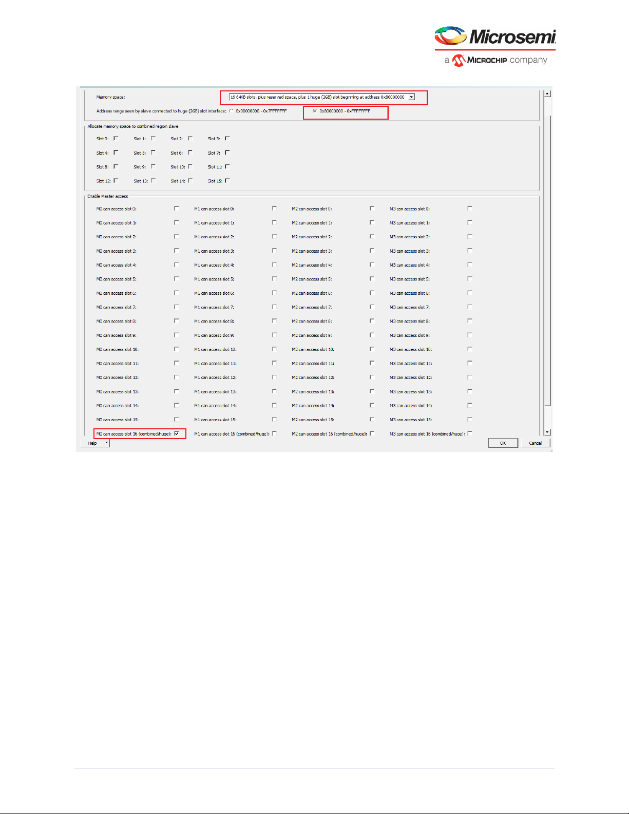
2.3.3.13 CoreAHBLite_0
CoreAHBLite_0 is configured as shown in Figure 12, page 13 to interface the PF_SRAM for accessing
the LSRAM at memory address 0x8000_0000. This configuration is required because the Mi-V processor
executes the code from 0x8000_0000.
Microsemi Proprietary DG0799 Demo Guide Revision 3.0 12
Page 18
PolarFire FPGA 1G Ethernet Loopback Using IOD CDR
Figure 12 • CoreAHBLite_0 Configuration
2.3.3.14 CoreAHBLite_2
CoreAHBLite_2 is configured as shown in Figure 13, page 14 to interface the APB peripherals to the MiV processor at 0x6000_0000.
Microsemi Proprietary DG0799 Demo Guide Revision 3.0 13
Page 19

PolarFire FPGA 1G Ethernet Loopback Using IOD CDR
Figure 13 • CoreAHBLite_2 Configuration
2.3.3.15 CoreAPB3
CoreAPB3 is configured as shown in Figure 14, page 15 to connect the peripherals CoreTSE, CoreSPI,
and CoreUARTapb as slaves.
• APB Master Data bus width: 32 bit
• Number of address bits driven by master: 16. The Mi-V processor addresses slaves using 16-bit
addressing, so the final address for these slaves translates to 0x6000_0000, 0x6000_1000, and
0x6000_2000
• Enabled APB Slave Slots: S0, S1, and S2 (for CoreTSE, CoreUARTapb, and CoreSPI, respectively).
Microsemi Proprietary DG0799 Demo Guide Revision 3.0 14
Page 20

PolarFire FPGA 1G Ethernet Loopback Using IOD CDR
Figure 14 • CoreAPB3 Configuration
2.3.3.16 COREAHBTOAPB3_0
The COREAHBTOAPB3 IP is used to bridge between AHB and APB3. This IP retains the default
configuration.
Microsemi Proprietary DG0799 Demo Guide Revision 3.0 15
Page 21

PolarFire FPGA 1G Ethernet Loopback Using IOD CDR
PF_CCC_0
Onboard 50 MHz Oscillator
Onboard ZL 30364
Clock generaion hardware
Mi-V
softprocessor
Clock Source 1 Clock Source 2
High-Speed Bank
Clocks for CDR
625MHz
50 MHz
80 MHz
CoreSPI_0
OUT0_FABCLK_0
Pf_sram_0
HCLK
CLK
MTXCLK
MRXCLK
PCLK
125 MHz
125 MHz
Onboard
VSC8575
PHY
125 MHz
PCLK
0,90,180,270
PF_IOD_CDR_CCC
PF_IOD_CDR
RX_CLK_R
TXCLK
RXCLK
CoreTSE
TBI_TX_CLK
TBI_RX_CLK
TX_CLK_G_TO_CDR
2.4 Clocking Structure
In the demo design, there are two clock sources—the on-board 50 MHz oscillator and the on-board
ZL30364 clock generation hardware.
• On-board 50 MHz oscillator: This oscillator drives the PLL that generates an 80-MHz clock for the
Mi-V soft processor and peripherals. In this design, Mi-V processor runs at 80 MHz.
• On-board ZL 30364 clock generation hardware: This hardware generates the reference clocks for
the VSC PHY, the IOD CDR fabric module, and CoreTSE.
Figure 15, page 16 shows the clocking structure of the demo design.
Figure 15 • Clocking Structure
Microsemi Proprietary DG0799 Demo Guide Revision 3.0 16
Page 22

Libero Design Flow
3 Libero Design Flow
This chapter describes the Libero design flow for running this demo design, which includes:
• Synthesize, page 18
• Place and Route, page 18
• Verify Timing, page 18
• Generate FPGA Array Data, page 19
• Configure Design Initialization Data and Memories, page 20
• Generate Bitstream, page 21
• Run PROGRAM Action, page 21
The following figure shows these options in the Design Flow tab.
Figure 16 • Libero Design Flow Options
Microsemi Proprietary DG0799 Demo Guide Revision 3.0 17
Page 23

Libero Design Flow
3.1 Synthesize
To synthesize the design:
1. On the Design Flow tab, double-click Synthesize.
When the synthesis is successful, a green tick mark appears next to Synthesize, as shown in
Figure 16, page 17.
2. Right-click Synthesize and select View Report to view the synthesis report and log files in the
Reports tab.
We recommend viewing the top.srr and top_compile_netlist.log files for debugging synthesis and compile errors.
3.2 Place and Route
The demo project includes the IO PDC file and the floor planner PDC constraint files. The Place and
Route process uses these PDC files to place the I/Os and CCC macros.
To place and route the design:
1. On the Design Flow tab, double-click Place and Route.
When place and route is successful, a green tick mark appears next to Place and Route, as shown
in Figure 16, page 17.
2. Right-click Place and Route and select View Report to view the place and route report and the log
files in the Reports tab.
We recommend viewing the top_place_and_route_constraint_coverage.xml file for
place and route constraint coverage.
3.2.1 PLL, DLL, and Lane Controller Placement
PolarFire FPGA I/O pairs are grouped into lanes. Each I/O bank has multiple lanes. Each lane consists of
twelve I/Os (six I/O pairs), a lane controller, and a set of high-speed, low-skew clock resources.
All associated I/Os must be placed in one lane. For example, RX_P and RX_N must be placed in the
same lane. For more information, see UG0686: PolarFire FPGA User I/O User Guide. The IO Editor
shows the placement of the components and I/Os. The PLL of PF_CCC and the PLL, DLL, and Lane
Controller of PF_IOD_CDR_CCC_C0 are auto placed by Libero SoC.
3.2.2 Resource Utilization
The resource utilization report is written to the top_layout_log.log file in the Reports tab under
iog_cdr_1Gbps reports > Place and Route. Table 3, page 18 lists the resource utilization of the design
after place and route. These values may vary slightly for different Libero runs, settings, and seed values.
Table 3 • Resource Utilization
Type Used Total Percentage
4LUT 22551 299544 7.53
DFF 12703 299544 4.24
I/O register 0 510 0.00
Logic Elements 24090 299544 8.04
User I/O 21 512 4.10
– Single-ended I/O 17 512 3.32
– Differential I/O pairs 3 256 1.17
3.3 Verify Timing
To verify timing:
Microsemi Proprietary DG0799 Demo Guide Revision 3.0 18
Page 24

Libero Design Flow
1. On the Design Flow tab, double-click Verify Timing.
When the design successfully meets the timing requirements, a green tick mark appears next to Ver-
ify Timing, as shown in Figure 16, page 17.
2. Right-click Verify Timing and select View Report to view the verify timing report and log files in the
Reports tab.
3.4 Generate FPGA Array Data
On the Design Flow tab, double-click Generate FPGA Array Data.
When the FPGA array data is successfully generated, a green tick mark appears next to Generate
FPGA Array Data, as shown in Figure 16, page 17.
Microsemi Proprietary DG0799 Demo Guide Revision 3.0 19
Page 25

Libero Design Flow
3.5 Configure Design Initialization Data and Memories
The fabric RAM blocks must be initialized with the user application to configure the PHY and
management registers of CoreTSE. The user application (HEX file) is generated using SoftConsole. This
step is used to select the fabric RAM client (HEX file), its storage location (sNVM/µPROM/SPI Flash),
and generate the fabric RAM client. The non-volatile memory is programmed with this client and at
device power-up, the fabric RAM blocks are initialized with the content from the selected NVM.
The Configure Design Initialization Data and Memories option creates the LSRAM initialization client.
When the PolarFire device powers up, the LSRAM memory is initialized with the sNVM contents.
To create the LSRAM initialization client:
1. On the Design Flow tab, double-click Configure Design Initialization Data and Memories, as
shown in Figure 17, page 20.
Figure 17 • Configure Design Initialization Data and Memories Option
2. In the Fabric RAMs tab, configure the pf_sram instance and to ensure that the fabric LSRAM
contents are stored in sNVM, set the Storage Type as sNVM as shown in Figure 18, page 20.
Figure 18 • Fabric RAMs Tab
3. Import the hex file (iog_cdr.hex)from:
mpf_dg0799_eval_liberosocv12p1_df\Libero_Project.
The iog_cdr.hex file is an application file generated using SoftConsole v6.0 that configures the
ZL clock generation hardware, the CoreTSE registers, and the VSC PHY. The application code is initially stored in sNVM. On device power-up, the system controller copies the code to LSRAM, and the
Mi-V processor executes the code from LSRAM.
4. Click Apply, as shown in Figure 19, page 21.
Microsemi Proprietary DG0799 Demo Guide Revision 3.0 20
Page 26

Libero Design Flow
Figure 19 • Fabric RAM Tab Apply Option
5. On the Design Flow tab, double-click Generate Design Initialization Data.
When the LSRAM initialization client is successfully generated in sNVM, a green tick mark appears
next to Generate Design Initialization Data, as shown in Figure 16, page 17.
When the device is programmed, the LSRAM block is initialized from the sNVM.
3.6 Generate Bitstream
To generate the bitstream:
1. On the Design Flow tab, double-click Generate Bitstream.
When the bitstream is successfully generated, a green tick mark appears next to Generate Bit-
stream, as shown in Figure 16, page 17.
2. Right-click Generate Bitstream and select View Report to view the corresponding log file in the
Reports tab.
3.7 Run PROGRAM Action
After generating the bitstream, the PolarFire device must be programmed. The programming procedure
involves setting up board and invoking the programming command from Libero.
Follow these steps:
Note: If you want to program the board using the .job file instead, see Programming the Device Using
FlashPro, page 26.
1. Ensure that the jumper settings on the board are as listed in the following table.
Table 4 • Jumper Settings
Jumper Setting
J18, J19, J20, J21,
and J22
J28 Close pins 1 and 2 for programming through the on-board FlashPro5.
J4 Close pins 1 and 2 for switching the power manually using SW3.
J12 Close pins 3 and 4 for 2.5 V.
2. Connect the power supply cable to the J9 connector on the board.
3. Connect the USB cable from the host PC to J5 (FTDI port) on the board.
Close pins 2 and 3 for programming through FTDI.
Microsemi Proprietary DG0799 Demo Guide Revision 3.0 21
Page 27

Libero Design Flow
4. Connect the RJ45 cable from the host PC to the J15 connector (RJ45-PORT 0) on the board. This is
required for the Ethernet link after programming.
The following figure shows the board setup for programming the device.
Figure 20 • Board Setup
5. Power up the board using the SW3 slide switch.
6. On the Libero Design Flow tab, double-click Run PROGRAM Action.
When the device is successfully programmed, the LEDs 6, 7, 8, 9, 10, and 11 on the board glow, and
a green tick mark appears, as shown in Figure 16, page 17.
7. Right-click Run Program Action and select View Report to view the corresponding log file in the
Reports tab.
The demo is ready to be run. For information about how to run the demo, see Running the Demo,
page 25.
Microsemi Proprietary DG0799 Demo Guide Revision 3.0 22
Page 28

Programming the Device Using FlashPro Express
or
4 Programming the Device Using FlashPro
Express
This chapter describes how to program the PolarFire device with the job file using Flashpro Express. The
job file is available at the following design files folder location:
mpf_dg0799_eval_liberosocv12p1_df\Programming_Job
Follow these steps:
1. Connect the jumpers and set up the PolarFire Evaluation Kit Board as described in steps 1 to 5 of
Run PROGRAM Action, page 21.
2. On the host PC, start the FlashPro Express software from
<$Installation Directory>\Microsemi\Libero_SoC_v12.1\Designer\binfp.
3. Select New or New Job Project from FlashPro Express Job from Project menu to create a new
job project, as shown in Figure 21, page 23.
Figure 21 • FlashPro Express Job Project
4. Enter the following in the New Job Project from FlashPro Express Job dialog box:
• Programming job file: Click Browse, and navigate to the location where the job file is located
and select the file. The default location is:
mpf_dg0799_eval_liberosocv12p1_df\Programming_Job
• FlashPro Express job project location: Select Browse and navigate to the location where
you want to save the project.
Figure 22 • New Job Project from FlashPro Express Job
5. Click OK. The required programming file is selected and ready to be programmed in the device.
Microsemi Proprietary DG0799 Demo Guide Revision 3.0 23
Page 29

Programming the Device Using FlashPro Express
6. The FlashPro Express window appears as shown in Figure 23, page 24. Confirm that a programmer
number appears in the Programmer field. If it does not, confirm the board connections and click
Refresh/Rescan Programmers.
Figure 23 • Programming the Device
7. Click RUN to program the device. When the device is programmed successfully, a RUN PASSED
status is displayed as shown in Figure 24, page 24. See Running the Demo, page 25.
Figure 24 • FlashPro Express—RUN PASSED
8. Close FlashPro Express (Project > Exit).
Microsemi Proprietary DG0799 Demo Guide Revision 3.0 24
Page 30

Running the Demo
5 Running the Demo
This section describes how to run the 1G loopback demo. The procedure involves transmitting packets
from the network card of the host PC to the board using Cat Karat and verifying the packets transmitted
to and received from the board using Wireshark.
The following procedure assumes that:
• The PolarFire FPGA is programmed with the demo design programming file (.job). For more
information, see Programming the Device Using FlashPro Express, page 23.
• The Cat Karat and the Wireshark softwares are installed on the host PC.
To run the demo:
1. Ensure that the RJ45 cable is connected from the host PC to the J15 connector on the board.
2. Power up the board using the SW3 slide switch.
3. Confirm that LED 7 is glowing, indicating the Ethernet PHY link is up and running.
4. Open the Cat Karat software from Start menu of the host PC.
The Cat Karat Packet Builder window opens, as shown in Figure 25, page 25.
Figure 25 • Cat Karat Packet Builder Window
Microsemi Proprietary DG0799 Demo Guide Revision 3.0 25
Page 31

Running the Demo
5. From the control panel of the host PC, note the name of Ethernet Network connection, as shown in
Figure 26, page 26. On a Windows 10 machine, this connection is Ethernet.
Figure 26 • Host PC Ethernet Network Connection
6. In the Cat Karat Packet Builder window > Interfaces pane, double-click the Ethernet Network
connection noted in the previous step to select that interface, as shown in Figure 27, page 26.
Figure 27 • Interface Selection
Microsemi Proprietary DG0799 Demo Guide Revision 3.0 26
Page 32

Running the Demo
7. In Packet Flow pane, select the use RAW check box, and set Packets per Burst to 5 and the Data
Pattern to 55, as shown in Figure 28, page 27.
Figure 28 • Packet Flow and View Settings
8. Open the Wireshark software from the Start menu of the host PC.
Figure 29, page 27 shows the Wireshark window.
Figure 29 • Wireshark Main Window
Microsemi Proprietary DG0799 Demo Guide Revision 3.0 27
Page 33

Running the Demo
9. Double-click Local Area Connection and select the interface settings, as shown in Figure 30,
page 28. On a Window 10 machine, select Ethernet.
Figure 30 • Wireshark Interface Settings
10. Click the Start a new live capture icon, as shown in Figure 31, page 28.
Figure 31 • Wireshark - Start a New Live Capture Icon
Microsemi Proprietary DG0799 Demo Guide Revision 3.0 28
Page 34

Running the Demo
The Wireshark live capture displays the Ethernet packets transferred from the board to the host PC
network card, as shown in Figure 32, page 29.
Figure 32 • Wireshark Live Capture
11. In the Cat Karat window, click Start Transmit to transmit five packets from the host PC to the board,
as shown in Figure 33, page 29.
Figure 33 • Car Karat - Transmit Packets Icon
Microsemi Proprietary DG0799 Demo Guide Revision 3.0 29
Page 35

Running the Demo
12. Verify that 10 packets have been captured (transmitted and received), as shown in Figure 34,
page 30.
Figure 34 • Transmitted and Looped Back Packets
The preceding figure highlights five packets that were transmitted from the host PC to the board,
looped back at the CoreTSE IP, and sent back to the host PC. All packets transmitted from host PC
network are looped back in the same way.
13. Select different burst rate and data pattern, and transmit packets to the board.
14. Power down the board, and close the Cat Karat and the Wireshark software.
You have successfully run the demo.
Microsemi Proprietary DG0799 Demo Guide Revision 3.0 30
Page 36

Appendix: Multi-Lane 1G IOD CDR Design
GPIO
Bank 5
Transceiver Lane
16-24 Lanes
NW
Corner
GPIO
Bank 4
HSIO
Bank 1
HSIO
Bank 7
HSIO
Bank 0
NE
Corner
SW
Corner
SE
Corner
HSIO
Bank 6
GPIO
Bank 2
JTAG/SPI
Bank 3
6 Appendix: Multi-Lane 1G IOD CDR Design
In a multi-lane design, Ethernet traffic from multiple RJ45 cables, comes into the FPGA via PHY. In such
cases, multiple RX and TX ports must be assigned from the PolarFire GPIO Banks to form multiple
SGMII links with the PHY. The following figure shows the placement of I/O Banks and PLLs in a PolarFire
device (MPF300).
Figure 35 • I/O Banks and PLL placement in MPF300
Each Bank has multiple I/O Lanes and each I/O Lane includes 6 I/O pairs. The lane controller available in
each I/O lane has a clock recovery unit, which is used for the Clock recovery of that lane. Hence, only
one SGMII link can be realized from an I/O lane.
For an 8-lane design, 8 I/O Lanes are used to form 8 SGMII links. To enable sharing of the
PF_IOD_CDR_CCC, the selection of these I/O Lanes must be made in any of the following ways:
• Lanes of the same Bank can be selected vertically upto half of the side
• Lanes of the same Bank can be selected horizontally upto half of the side
• Lanes from vertical and horizontal Banks can be selected
Note: In Libero SoC, when I/O lanes are selected from Bank 5 or 2, or from both and placed, the
PF_IOD_CDR_CCC selects the SW PLL and is placed SW. If all I/O lanes are selected from Bank 4,
PF_IOD_CDR_CCC selects the NW PLL and is placed NW.
When the reference clock for all the links is same:
• PF_IOD_CDR_CCC can be shared across all IOD blocks (PF_IOD_CDR) for the HSIO BANK
clocks and transmit clock (TX_CLK).
• PF_IOD_CDR_CCC uses an internal lane controller to generate the DLL delay code and shares it
with all IOD blocks. The DLL delay code is required for phase tuning/adjustment.
Microsemi Proprietary DG0799 Demo Guide Revision 3.0 31
Page 37

Appendix: Multi-Lane 1G IOD CDR Design
Board
RJ45
RJ45
RJ45
RJ45
RJ45
RJ45
RJ45
RJ45
PHY FPGA
RX
TX
RX
TX
RX
TX
RX
TX
RX
TX
RX
TX
RX
TX
RX
TX
GPIO BANK 5
GPIO BANK 2
PF_IOD_CDR_0
PF_IOD_CDR_1
PF_IOD_CDR_2
PF_IOD_CDR_3
PF_IOD_CDR_4
PF_IOD_CDR_5
PF_IOD_CDR_6
PF_IOD_CDR_7
REF_CLK
PF_IOD_CDR_CCC
(SW Corner)
0°
90°
180°
270°
DLL_DELAY_CODE
TX_CLK_G_TO_CDR
RX_CLK_R
RX_CLK_R
RX_CLK_R
RX_CLK_R
RX_CLK_R
RX_CLK_R
RX_CLK_R
RX_CLK_R
LINK 1
LINK 2
LINK 3
LINK 4
LINK 5
LINK 6
LINK 7
LINK 8
DLL_DELAY_CODE
DLL_DELAY_CODE
DLL_DELAY_CODE
DLL_DELAY_CODE
DLL_DELAY_CODE
DLL_DELAY_CODE
DLL_DELAY_CODE
TX_CLK_G
TX_CLK_G
TX_CLK_G
TX_CLK_G
TX_CLK_G
TX_CLK_G
TX_CLK_G
To conclude, the following IOD resources are used to create an 8-lane design in a PolarFire MPF300
device:
• One PF_IOD_CDR_CCC with a lane controller for DLL delay update
• 8 I/O Lanes and lane controllers for clock recovery
•
The following figure shows the high-level block diagram of an 8-lane design implemented using Libero
SoC PolarFire.
Figure 36 • 8 Lane 1G IOD CDR Design in PolarFire
As shown in Figure 36, page 32, eight PF_IOD_CDR instances are instantiated from GPIO Banks 5 and
2 to form eight links. The clock conditioning circuit (CCC) available in the South-West corner, is
configured in the PLL-DLL cascaded mode for the clock recovery and DLL delay update.
Apart from 8 lane controllers for clock recovery, an additional lane controller from the
PF_IOD_CDR_CCC is inferred during synthesis for sharing the DLL delay update. This optimizes the
utilization of lane controllers in the device.
Microsemi Proprietary DG0799 Demo Guide Revision 3.0 32
Page 38

Appendix: 1G Ethernet BASE-T and BASE-X Using Transceiver
1G Ethernet BASE-T
Link
Partner
XCVR
MAC
(CoreTSE/
CoreSGMII)
Mi-V
Soft
Processor
User Interface
Copper
PHY
FPGA Board
FPGA
Auto-negotiation
By PHY
Auto-negotiation By MAC
SGMII
TBI
MDIO Interface
1G Ethernet BASE-X
Link
Partner
XCVR
MAC
(CoreTSE/
CoreSMII)
Mi-V
Soft
Processor
User Interface
Optical SFP
Pluggable
Module
FPGA Board
FPGA
Auto-negotiation By MAC
TBI
SGMII
7 Appendix: 1G Ethernet BASE-T and BASE-X
Using Transceiver
The PolarFire FPGA family includes multiple embedded low-power, performance-optimized transceivers.
Each transceiver has both the physical medium attachment (PMA), protocol physical coding sub-layer
(PCS) logic, and interfaces to the FPGA fabric. The transceiver has a multi-lane architecture with each
lane natively supporting serial data transmission rates from 250 Mbps to 12.7 Gbps. For more
information, see UG0677: PolarFire FPGA Transceiver User Guide.
This section describes how 1G Ethernet BASE-T and BASE-X designs are implemented in PolarFire
FPGAs using the transceivers.
7.1 1G Ethernet BASE-T and BASE-X
Figure 37, page 33 shows the typical FPGA design for 1G Ethernet BASE-T.
Figure 37 • 1G BASE-T Design
Figure 38, page 33 shows the typical FPGA design for 1G Ethernet BASE-X.
Figure 38 • 1G BASE-X Design
Microsemi Proprietary DG0799 Demo Guide Revision 3.0 33
Page 39

Appendix: 1G Ethernet BASE-T and BASE-X Using Transceiver
The following points summarize the 1G Ethernet BASE-T and BASE-X designs:
• The Mi-V soft processor is used to configure the PHY registers (using MDIO interface), MAC
Configuration and Management registers. User can also implement a fabric logic or any other soft
processor to implement these functions.
• The MAC IP is configured in the ten bit interface mode (TBI).
• In BASE-T, the management block of the MAC IP auto-negotiates with the on-board PHY as per
Clause 28 of the IEEE802.3z standard. The PHY auto-negotiates with the link partner.
• In BASE-X, the management block of the MAC IP auto-negotiates with the link partner as per
Clause 37 of the IEEE802.3z standard.
• The auto-negotiation (AN) functions are defined in the MAC Management registers 04h to 08h. The
bit field formats of these registers are different for BASE-T and BASE-X. For more information about
the bit field formats of the AN registers, see HB0549: CoreTSE v3.1 Handbook or HB0627:
CoreSGMII v3.2 Handbook. The following table lists the AN registers.
Table 5 • AN Registers
Register Description
04h AN Advertisement
05h AN Link Partner
Base Page Ability
06h AN Expansion
07h AN Next Page
Transmit
08h AN Link Partner
Ability Next Page
The following registers are common in BASE-T and BASE-X modes:
• Control register at address 0x00
• Status register at address 0x01
Registers 0x04, 0x05, 0x06, 0x07, and 0x08 are based on the configuration.
• XCVR is configured to operate at 1250 Mbps. For more information about XCVR configuration, see
Transceiver Configuration, page 34.
• The user data from MAC (CoreTSE non-AHB) is provided on a 32-bit parallel bus.
7.2 Transceiver Configuration
For 1G Ethernet BASE-T and BASE-X, the transceiver block is configured for 1.25 Gbps data rate.
Figure 39, page 35 shows the configuration of the transceiver block in Libero SoC design suite. The
following table lists the transceiver configuration.
Table 6 • XCVR Configuration
Parameters Settings
Number of lanes 1
Data Rate 1250 Mbps
PMA
TX clock division factor 4
TX PLL base data rate 5000 Mbps
TX PLL bit clock frequency 2500 Mbps
CDR lock mode lock to data
CDR reference clock source Dedicated
Microsemi Proprietary DG0799 Demo Guide Revision 3.0 34
Page 40

Appendix: 1G Ethernet BASE-T and BASE-X Using Transceiver
Table 6 • XCVR Configuration (continued)
Parameters Settings
CDR reference clock frequency 125 MHz
PCS
PCS-fabric interface width 10 bits
FPGA interface frequency 125 MHz
PMA Mode Enabled
Clocks and Resets
TX clock Regional
RX clock Regional
PCS Reset RX Only
Figure 39 • Transceiver Configuration
7.3 Transceiver Connections
This section describes the typical transceiver to CoreTSE connections in BASE-T and BASE-X design.
The following table lists the transceiver input and output port connections.
Table 7 • XCVR Port Connections
Port Name Input or Output Connection Description
CTRL_CLK Input 40 MHz clock for the enhanced
CTRL_ARST_N Input signal to reset ERM. Drive this
Microsemi Proprietary DG0799 Demo Guide Revision 3.0 35
receiver management logic
Can be sourced from the on-chip 160
MHz RC oscillator through a clock
divider
or
Can be connected to the output fabric
clock of CCC
signal from the XCVR_INIT_DONE
signal of the PF_INIT_MONITOR
component.
Page 41

Appendix: 1G Ethernet BASE-T and BASE-X Using Transceiver
Table 7 • XCVR Port Connections (continued)
Port Name Input or Output Connection Description
CLKS_FROM_TX_PLL XCVR transmit clock sourced from the
LANE0_RXD_N
LANE0_RXD_P
LANE0_CDR_REF_CLK 125 MHz reference for clock and data
LANE0_PCS_ARST_N Asynchronous active-low reset signal
LANE0_PMA_ARST_N Asynchronous active-low reset signal
LANE0_RX_DATA[9:0] The 10-bit RX data from XCVR to
LANE0_TXD_N
LANE0_TXD_P
LANE0_RX_CLK_R Recovered regional receive clock from
LANE0_TX_DATA[9:0] The 10-bit TX data from
TX PLL.
Differential receive input pads for
receiving the Ethernet data.
recovery.
used to reset the PCS module of
XCVR lane.
used to reset the PMA module of
XCVR lane.
CoreTSE:RCG[9:0].
Differential transmit output pads.
XCVR to the fabric logic and
CoreTSE:TBI_RX_CLK.
CoreTSE:TCG[9:0] to XCVR.
For other XCVR ports, see UG0677: PolarFire FPGA Transceiver User Guide.
Microsemi Proprietary DG0799 Demo Guide Revision 3.0 36
Page 42

Appendix: References
8 Appendix: References
This section lists documents that provide more information about and about the IP cores used in the 1G
loopback demo design and about PolarFire 1G Ethernet Solutions in general.
• For more information about PF_IOD_CDR_CCC and PF_IOD_CDR, see UG0686: PolarFire FPGA
User I/O User Guide.
• For more information about CoreTSE, see HB0549: CoreTSE Handbook.
• For more information about PF_CCC, see UG0684: PolarFire FPGA Clocking Resources User
Guide.
• For more information about PF_SRAM_AXI_AHBL, see UG0680: PolarFire FPGA Fabric User
Guide.
• For more information about CoreAHBLite, see CoreAHBLite Handbook.
• For information about COREAHBTOAPB3, see COREAHBTOAPB3 Handbook.
• For more information about CoreAPB3, see CoreAPB3 Handbook.
• For more information about CoreUARTapb, see CoreUARTapb Handbook.
• For more information about CoreSPI, see HB0089: CoreSPI Handbook.
• For more information about PF_INIT_MONITOR, see UG0725: PolarFire FPGA Device Power-Up
and Resets User Guide.
• For more information about Mi-V soft processor, see MIV_RV32IMA_L1_AHB Handbook from the
Libero Catalog.
• For general information about PolarFire 1G Ethernet Solutions, see UG0687: PolarFire FPGA 1G
Ethernet Solutions User Guide.
• For more information about the PolarFire Evaluation board, see UG0747: PolarFire FPGA
Evaluation Kit User Guide.
Microsemi Proprietary DG0799 Demo Guide Revision 3.0 37
 Loading...