

Page 1

PDS-408G Web Management
User Guide
Ver. 1.0.1, 03-2019
Page 2

Introduction Objectives
Microsemi makes no warranty, representation, or guarantee regarding the
Microsemi, a wholly owned subsidiary of Microchip Technology Inc. (Nasdaq:
information contained herein or the suitability of its products and services for
any particular purpose, nor does Microsemi assume any liability whatsoever
arising out of the application or use of any product or circuit. The products
sold hereunder and any other products sold by Microsemi have been subject
Microsemi Headquarters
One Enterprise, Aliso Viejo, CA 92656 USA
Within the USA: +1 (800) 713-4113
Outside the USA: +1 (949) 380-6100
Sales: +1 (949) 380-6136
Fax: +1 (949) 215-4996
Email: sales.support@microsemi.com
www.microsemi.com
© 2019 Microsemi. All rights reserved.
Microsemi and the Microsemi logo are
trademarks of Microsemi Corporation. All
other trademarks and service marks are the
property of their respective owners.
to limited testing and should not be used in conjunction with mission-critical
equipment or applications. Any performance specifications are believed to be
reliable but are not verified, and Buyer must conduct and complete all
performance and other testing of the products, alone and together with, or
installed in, any end-products. Buyer shall not rely on any data and
performance specifications or parameters provided by Microsemi. It is the
Buyer's responsibility to independently determine suitability of any products
and to test and verify the same. The information provided by Microsemi
hereunder is provided "as is, where is" and with all faults, and the entire risk
associated with such information is entirely with the Buyer. Microsemi does
not grant, explicitly or implicitly, to any party any patent rights, licenses, or any
other IP rights, whether with regard to such information itself or anything
described by such information. Information provided in this document is
proprietary to Microsemi, and Microsemi reserves the right to make any
changes to the information in this document or to any products and services
at any time without notice.
MCHP), offers a comprehensive portfolio of semiconductor and system
solutions for aerospace & defense, communications, data center and
industrial markets. Products include high-performance and radiation-hardened
analog mixed-signal integrated circuits, FPGAs, SoCs and ASICs; power
management products; timing and synchronization devices and precise time
solutions, setting the world's standard for time; voice processing devices; RF
solutions; discrete components; enterprise storage and communication
solutions; security technologies and scalable anti-tamper products; Ethernet
solutions; Power-over-Ethernet ICs and midspans; as well as custom design
capabilities and services. Microsemi is headquartered in Aliso Viejo,
California, and has approximately 4,800 employees globally. Learn more at
www microsemi.com
Microsemi PDS-408G Web Management User Guide Ver. 1.0.1, 03-2019 2
Page 3

Introduction Objectives
TABLE OF CONTENTS
1 INTRODUCTION ...................................................................................................................................... 10
1.1 Objectives .................................................................................................................................... 10
1.2 Abbreviations ............................................................................................................................... 10
1.3 Front panel – Quick Overview ..................................................................................................... 10
1.4 Reset Button ................................................................................................................................ 10
1.5 Power and System LEDs ............................................................................................................. 11
1.6 USB Interface (virtual COMM) ..................................................................................................... 11
1.7 RJ45 Ports 1-8 ............................................................................................................................. 12
1.8 RJ45 Ports 9-10 ........................................................................................................................... 12
1.9 SFP Ports 11 ............................................................................................................................... 12
2 MANAGING THE UNIT OVER THE WEB – A GENERAL WALK-THROUGH ...................................... 13
2.1 Default unit IP, username and password. ................................................................................... 13
2.2 Web interface overview ............................................................................................................... 13
2.3 Saving configuration changes ..................................................................................................... 14
2.3.1 Configuration profiles ................................................................................................................................. 14
2.3.2 Saving unit configuration over Web and CLI .............................................................................................. 15
3 OVERVIEW .............................................................................................................................................. 16
3.1 Unit Overview .............................................................................................................................. 16
3.1.1 RJ45 LEDs and connecter jack .................................................................................................................. 17
3.1.2 Ports Status/Reset ..................................................................................................................................... 18
3.1.3 Unit Status ................................................................................................................................................. 20
3.2 Unit network Traffic Overview ...................................................................................................... 20
3.2.1 Port Statistics Overview ............................................................................................................................. 20
3.2.2 Detailed Port Statistics ............................................................................................................................... 21
3.3 Overview – Unit System Information ........................................................................................... 21
4 NETWORK (IPS MAC) ............................................................................................................................ 22
4.1 Network - Configuration - Ethernet Ports .................................................................................... 23
4.2 Network - Configuration – Ipv4/6 ................................................................................................. 24
4.2.1 DNS Servers .............................................................................................................................................. 24
4.2.2 IPv4 / IPv6 Interfaces ................................................................................................................................. 24
4.2.2.1 Static IPv4 Address Configuration ....................................................................................................... 24
4.2.2.2 Dynamic DHCPv4 IPv4 Address Configuration ................................................................................. 25
4.2.2.3 Static/Dynamic DHCPv6 Address Configuration ............................................................................... 25
4.2.3 IP Routes (Default-Gateway) confi guration ................................................................................................ 25
4.3 Network - Configuration – NTP (Network Time Protocol) ........................................................... 26
4.4 Network - Configuration – Time Zone ......................................................................................... 26
4.4.1 Time Zone Configuration ............................................................................................................................ 26
4.4.2 Daylight Saving Time Configurat ion. .......................................................................................................... 27
4.5 Network - Configuration – SysLog Report ................................................................................... 27
4.6 Network - Configuration – MAC Table learning ........................................................................... 27
4.6.1 Aging Configuration ................................................................................................................................... 28
Disable Automatic Aging .......................................................................................................................................... 28
Aging Time ................................................................................................................................................................. 28
4.6.2 MAC Table Learning .................................................................................................................................. 28
4.6.3 VLAN Learning-Disabled configuration ...................................................................................................... 29
4.6.4 Static MAC Table Configuration ................................................................................................................. 29
4.7 Network - View – MAC Table in use ............................................................................................ 30
Microsemi PDS-408G Web Management User Guide Ver. 1.0.1, 03-2019 3
Page 4

Introduction Objectives
4.8 Network - View – IP Status .......................................................................................................... 30
4.9 Network - View – Routing Info ..................................................................................................... 31
5 ACCESS CONTROL ................................................................................................................................ 32
5.1 Access Control – Local Users Configur a tion ............................................................................... 32
5.1.1 Changing the admin password ................................................................................................................... 32
5.1.2 Changing a username or a password ........................................................................................................ 32
5.2 Access Control – Web Server HTTPS Configuration .................................................................. 32
5.3 Access Control – Telnet/SSH/Web.............................................................................................. 33
5.3.1 Authentication Method Configur ation ......................................................................................................... 33
5.3.2 Accounting Method Configurati on .............................................................................................................. 34
5.4 Access Control – Access Cont rol List ......................................................................................... 35
5.5 Access Control – View ACL Statistics ......................................................................................... 35
6 VLAN ........................................................................................................................................................ 36
6.1 General ........................................................................................................................................ 36
6.1.1 Supported VLAN types .............................................................................................................................. 36
6.1.2 VLAN typing syntax .................................................................................................................................... 36
6.2 VLAN – Configuration .................................................................................................................. 36
6.2.1 Switch VLAN Terminology - explained ....................................................................................................... 37
6.2.2 Global VLAN Configuration ........................................................................................................................ 40
6.2.3 Port VLAN Configuration ............................................................................................................................ 41
6.3 VLAN - View Members ................................................................................................................ 43
6.4 VLAN – View Ports ...................................................................................................................... 44
7 POE-BT POWER ..................................................................................................................................... 45
7.1 General PoE background ............................................................................................................ 45
7.2 PoE-BT - Set PoE-BT Power ....................................................................................................... 46
7.2.1 Global Configuration .................................................................................................................................. 46
7.2.2 Global Configuration .................................................................................................................................. 46
7.3 PoE-BT - View PoE-BT ............................................................................................................... 47
8 SPANNING TREE - STP ......................................................................................................................... 49
8.1 General ........................................................................................................................................ 49
8.2 Spanning tree – Configuration - STP Config ............................................................................... 49
8.2.1 Basic Settings ............................................................................................................................................ 49
8.2.2 Advanced Settings ..................................................................................................................................... 50
8.3 Spanning Tree – Configuration - STP Port Config ...................................................................... 50
8.4 Spanning tree – View - STP Bridges ........................................................................................... 51
8.4.1 STP Detailed Bridge Status ....................................................................................................................... 51
8.4.2 CIST Ports & Aggregation State ................................................................................................................ 52
8.5 Spanning Tree - View - STP Port Status ..................................................................................... 53
8.6 Spanning Tree - View - STP Port Statistics ................................................................................. 53
9 SNMP ....................................................................................................................................................... 55
9.1 SNMP- Enable SNMP ................................................................................................................. 55
9.2 SNMP- SNMPv2-v3 configuration ............................................................................................... 56
9.2.1 SNMP View OiD-Range Configuration ....................................................................................................... 56
9.2.2 SNMP Community Configuration ............................................................................................................... 56
9.2.3 SNMP Group Configuration ....................................................................................................................... 57
9.2.4 SNMP Access Configuration ...................................................................................................................... 57
9.2.5 SNMP- SNMPv3 Users Configuration ........................................................................................................ 58
Microsemi PDS-408G Web Management User Guide Ver. 1.0.1, 03-2019 4
Page 5

Introduction Objectives
9.3 SNMP- Trap Configuration .......................................................................................................... 59
9.3.1 SNMP Trap Server List .............................................................................................................................. 59
9.3.2 SNMP Trap Source Configuration .............................................................................................................. 60
9.4 SNMP- Configuration example .................................................................................................... 60
9.4.1 SNMPv2 Configuration Example ................................................................................................................ 60
9.4.2 SNMPv3 Configuration Example ................................................................................................................ 61
10 RADIUS, TACACS+ ................................................................................................................................ 62
10.1 General ........................................................................................................................................ 62
10.1.1 General - Authentication, Access-Level terminology .................................................................................. 62
10.1.2 General - Setting up remote RADIUS Server ............................................................................................. 62
10.2 RADIUS TACACS+ - Configuration - RADIUS ............................................................................ 63
10.2.1 Global Configuration .................................................................................................................................. 63
10.2.2 Server Configuration .................................................................................................................................. 63
10.3 RADIUS TACACS+ - Configuration – TACACS+ ........................................................................ 64
10.3.1 Global Configuration .................................................................................................................................. 64
10.3.2 Server Configuration .................................................................................................................................. 64
10.4 RADIUS TACACS+ - View – RADIUS Status ............................................................................. 65
10.5 RADIUS TACACS+ - View – RADIUS Details............................................................................. 66
10.5.1 Packet Counters ........................................................................................................................................ 66
10.5.2 Other Info (RADIUS-Server IP address and state) ..................................................................................... 68
11 AGGREGATION/LACP ........................................................................................................................... 69
11.1 General ........................................................................................................................................ 69
11.2 Aggregation/LACP – Aggregation – Aggregation Configuration ................................................. 69
11.2.1 Aggregation Group Configuration .............................................................................................................. 69
11.2.2 Hash Contributors Configuration ................................................................................................................ 70
11.3 Aggregation Status ...................................................................................................................... 70
11.4 Aggregation/LACP - LACP- Configure LACP .............................................................................. 71
11.5 Aggregation/LACP – LACP – View – System Status .................................................................. 71
11.5.1 Local System ID ......................................................................................................................................... 72
11.5.2 Partner System Status ............................................................................................................................... 72
11.6 Aggregation/LACP – LACP – View – Internal Status .................................................................. 72
11.7 Aggregation/LACP – LACP – View – Neighbor Status................................................................ 73
11.8 Aggregation/LACP – LACP – View – Port Statistics ................................................................... 74
12 LLDP ........................................................................................................................................................ 75
12.1 LLDP – Configure LLDP .............................................................................................................. 75
12.1.1 LLDP Parameters ...................................................................................................................................... 75
12.1.2 LLDP Interface Configuration ..................................................................................................................... 75
12.2 LLDP – View Neighbor Information ............................................................................................. 77
12.3 LLDP – View LLDP Status ........................................................................................................... 78
12.3.1 Global Counters ......................................................................................................................................... 78
12.3.2 Local Counters ........................................................................................................................................... 78
13 PORT ISOLATION ................................................................................................................................... 80
13.1 Port Isolation – Configure Private VLAN ..................................................................................... 80
13.1.1 General ...................................................................................................................................................... 80
13.1.2 Private VLAN - configuration parameters ................................................................................................... 80
13.2 Port Isolation – Configure Port Isolation ...................................................................................... 80
13.2.1 General ...................................................................................................................................................... 80
13.2.2 Port Isolation - configuration parameters ................................................................................................... 81
Microsemi PDS-408G Web Management User Guide Ver. 1.0.1, 03-2019 5
Page 6

Introduction Objectives
14 LOOP PROTECTION ............................................................................................................................... 82
14.1 Loop Protection – Configure Protection ...................................................................................... 82
14.1.1 General Settings ........................................................................................................................................ 82
14.1.2 Port Configuration ...................................................................................................................................... 82
15 IGMP SNOOPING .................................................................................................................................... 83
15.1 General ........................................................................................................................................ 83
15.2 IGMP Snooping – Configuration – Global Settings ..................................................................... 83
15.2.1 IGMP Snooping Configuration ................................................................................................................... 83
15.2.2 Port Related Configuration ......................................................................................................................... 84
15.3 IGMP Snooping – Configuration – Enable per VLAN .................................................................. 84
15.3.1 IGMP Snooping Enable per VLAN ............................................................................................................. 84
15.4 IGMP Snooping – View – Groups Information ............................................................................ 85
15.4.1 IGMP Snooping Group Information ............................................................................................................ 85
15.4.2 IGMP SFM (Source-Filtered Multicast) Informat ion ................................................................................... 86
15.5 IGMP Snooping - View - Status ................................................................................................... 86
15.5.1 IGMP Snooping Status............................................................................................................................... 86
15.5.2 Router Port ................................................................................................................................................. 87
16 PORT MIRRORING ................................................................................................................................. 88
16.1 Port Mirroring - General ............................................................................................................... 88
16.1.1 Enable Ports Mirroring ............................................................................................................................... 88
16.1.2 Port Configuration ...................................................................................................................................... 88
17 MAINTENANCE ....................................................................................................................................... 90
17.1 Maintenance - Reset & restore unit ............................................................................................. 90
17.2 Maintenance – Unit Configuration ............................................................................................... 90
17.2.1 Download Unit configuration ...................................................................................................................... 90
17.2.2 Upload Unit Configuration .......................................................................................................................... 91
17.2.3 Activate Unit Configuration ......................................................................................................................... 91
17.2.4 Delete Unit Configuration ........................................................................................................................... 92
17.3 Maintenance – Software Update ................................................................................................. 92
17.3.1 Upload New Version .................................................................................................................................. 92
17.3.2 Select active image .................................................................................................................................... 93
17.3.3 Recovering from endless unit reboot after software update ....................................................................... 94
18 DIAGNOSTICS ........................................................................................................................................ 95
18.1 Diagnostics - View log file ............................................................................................................ 95
18.2 Diagnostics - Ping ........................................................................................................................ 96
18.3 Diagnostics - RJ45 Cable test ..................................................................................................... 97
18.4 Diagnostics – View CPU Load ..................................................................................................... 98
19 SAVE RUNNING CONFIG ....................................................................................................................... 99
Microsemi PDS-408G Web Management User Guide Ver. 1.0.1, 03-2019 6
Page 7

Introduction Objectives
LIST OF FIGURES
Figure 1-1: Unit front panel .................................................................................................................. 10
Figure 1-2: CLI interface example ....................................................................................................... 11
Figure 1-3: Windows 10 ports report ................................................................................................... 11
Figure 1-4 : Unit ports 1-8 (out of 11) .................................................................................................. 12
Figure 1-5: Unit ports 9-10 (out of 11) ................................................................................................. 12
Figure 1-6: Unit port 11 (out of 11) ...................................................................................................... 12
Figure 2-1: Unit overview main Web page .......................................................................................... 13
Figure 2-2: Save unit configuration ..................................................................................................... 15
Figure 3-1: Unit Overview .................................................................................................................... 16
Figure 3-2: Unit Overview .................................................................................................................... 18
Figure 3-3: Unit Status ........................................................................................................................ 20
Figure 3-4: Port Statistics Overview .................................................................................................... 20
Figure 3-5: Port Statistics Overview .................................................................................................... 21
Figure 3-6: System Information ........................................................................................................... 21
Figure 4-1: Ethernet Port Configuration .............................................................................................. 23
Figure 4-2: Static IPv4 Address Configuration. ................................................................................... 24
Figure 4-3: Dynamic/Static IPv6 Address Configuration. .................................................................... 25
Figure 4-4: IP Routes (Default-Gateway) configur ation ...................................................................... 26
Figure 4-5: NTP Server configuration .................................................................................................. 26
Figure 4-6: Time Zone Configuration .................................................................................................. 26
Figure 4-7: Daylight Saving Time Configuration ................................................................................. 27
Figure 4-8: SysLog configuration ........................................................................................................ 27
Figure 4-9: MAC Table learning configuration page. .......................................................................... 28
Figure 4-10: MAC Table Ageing Configuration ................................................................................... 28
Figure 4-11: MAC Table Learning ....................................................................................................... 28
Figure 4-12: VLAN Learning Configuration ......................................................................................... 29
Figure 4-13: Static MAC Table Configuration ..................................................................................... 29
Figure 4-14: View unit MAC Address Table ........................................................................................ 30
Figure 4-15: View unit in use IP address ............................................................................................ 30
Figure 4-16: View unit Routing Information ......................................................................................... 31
Figure 5-1: Web Server HTTP/HTTPS Configuration ......................................................................... 32
Figure 5-2: Unsecure HTTPS browsing warning ................................................................................. 32
Figure 5-3: Access Control – Telnet/SSH/Web ................................................................................... 33
Figure 5-4: Authentication Example .................................................................................................... 34
Figure 5-5: Accounting Method Configuration example ...................................................................... 34
Microsemi PDS-408G Web Management User Guide Ver. 1.0.1, 03-2019 7
Page 8

Introduction Objectives
Figure 5-6: Access Control List ........................................................................................................... 35
Figure 5-7: View ACL Statistics ........................................................................................................... 35
Figure 6-1: single and double VLAN tagging packet f ormat ............................................................... 36
Figure 6-2: VLAN configuration (global plus p er-port) ......................................................................... 37
Figure 6-3: VLAN Global configuration................................................................................................ 40
Figure 6-4: VLAN 802.1ad Q-in-Q double VLAN tagging .................................................................... 41
Figure 6-5: Port VLAN configuration ................................................................................................... 41
Figure 6-6: VLAN Membership Status................................................................................................. 43
Figure 6-7: VLAN Port Status for Combined users ............................................................................. 44
Figure 7-1: PoE-BT configuration ........................................................................................................ 46
Figure 7-2: PoE Port Configuration ..................................................................................................... 46
Figure 7-3: PoE status ......................................................................................................................... 47
Figure 7-4: PoE Class report ............................................................................................................... 48
Figure 8-1: STP Configuration ............................................................................................................. 49
Figure 8-2: STP Port Configuration ..................................................................................................... 50
Figure 8-3: View STP Bridges ............................................................................................................. 51
Figure 8-4: View STP Detailed Bridge Status ..................................................................................... 51
Figure 8-5: View STP Port Status ....................................................................................................... 53
Figure 8-6: View STP Port Statistics ................................................................................................... 53
Figure 9-1: Enable SNMP ................................................................................................................... 55
Figure 9-2: SNMPv2-v3 Configuration ................................................................................................ 56
Figure 9-3: SNMPv3 User Configuration ............................................................................................. 58
Figure 9-4: SNMP Trap Configuration ................................................................................................. 59
Figure 10-1: RADIUS Configuration .................................................................................................... 63
Figure 10-2: TACACS+ Configuration ................................................................................................. 64
Figure 10-3: RADIUS Authentication Statistics ................................................................................... 66
Figure 11-1: Aggregation Configuration .............................................................................................. 69
Figure 11-2: Aggregation Status ......................................................................................................... 70
Figure 11-3: LACP Configuration ........................................................................................................ 71
Figure 11-4: View LACP System Status.............................................................................................. 71
Figure 11-5: View LACP Internal Port Status ...................................................................................... 72
Figure 11-6: View LACP Neighbor Port Status ................................................................................... 73
Figure 11-7: View LACP Port Statistics ............................................................................................... 74
Figure 12-1: LLDP Configuration ......................................................................................................... 75
Figure 12-2: LLDP Neighbor ............................................................................................................... 77
Figure 12-3: View LLDP Status ........................................................................................................... 78
Microsemi PDS-408G Web Management User Guide Ver. 1.0.1, 03-2019 8
Page 9

Introduction Objectives
Figure 13-1: Private VLAN Membership Configurat i on ....................................................................... 80
Figure 13-2: Port Isolation Configuration ............................................................................................ 81
Figure 14-1: Loop Protection Configuration ........................................................................................ 82
Figure 15-1: IGMP Global Settings ..................................................................................................... 83
Figure 15-2: IGMP Snooping VLAN Configuration .............................................................................. 84
Figure 15-3: View IGMP Snooping Groups Information ...................................................................... 85
Figure 15-4: View IGMP Snooping Status .......................................................................................... 86
Figure 16-1: Port Mirroring .................................................................................................................. 88
Figure 17-1: Maintenance - Reset and Restore unit ........................................................................... 90
Figure 17-2: Maintenance – Download unit configuration ................................................................... 90
Figure 17-3: Maintenance – Activate unit configuration ...................................................................... 91
Figure 17-4: Software Update – in progress indication ....................................................................... 92
Figure 17-5: Selecting active software image ..................................................................................... 93
Figure 17-6: Switching active image ................................................................................................... 93
Figure 17-7: Recovering from endless reboot aft er software update .................................................. 94
Figure 18-1: View SysLog file .............................................................................................................. 95
Figure 18-2: Detailed single SysLog message .................................................................................... 95
Figure 18-3: Ping Web interface .......................................................................................................... 96
Figure 18-4: Ping in action .................................................................................................................. 96
Figure 18-5: RJ45 cables test ............................................................................................................. 97
Figure 18-6: Switch CPU load ............................................................................................................. 98
Microsemi PDS-408G Web Management User Guide Ver. 1.0.1, 03-2019 9
Page 10

Introduction Objectives
IPv4
32-bit long IP address
IPv6
128-bit long IP address
DHCPv4
Dynamic IPv4 Host Configuration Protocol
DHCPv6
Dynamic IPv6 Host Configuration Protocol
PoE
Power over Ethernet
NTP
Network Time Protocol
DES
Data Encryption Standard
AES
Advanced Encryption Standard
MD5
Message Digest algorithm 5
SHA
Secure Hash Algorithm
MDI
Media Dependent Interface
MIB
Management Information Base
PD
Powered Device
SNMP
Simple Network Management Protocol
SSL
Secure Sockets Layer
TFTP
Trivial File Transfer Protocol
SysLog
System Log
SSH
Secure Shell
RADIUS
Remote Authentication Dial In User Service
TACACS+
Terminal Access Controller Access-Control System Plus
IGMP
Internet Group Management Protocol
1 INTRODUCTION
The following sections describe the manual object ives, concepts used, conventions used, and
associated documentation.
1.1 Objectives
This User Guide introduces Microsemi’s PDS-408G 802.3BT PoE 90W IPv4, IPv6 Ethernet Switch Web
Management configuration and maintenance inte rface.
1.2 Abbreviations
Table 1-1: List of Abbreviations
1.3 Front panel – Quick Overview
1.4 Reset Button
• Press button for less than 2 seconds and release: Does nothing.
• Press button for 2-10 seconds and release: Reset switch by software (no configuration
change).
• Press button for more than 10 seconds and release: Restore unit to factory default.
Microsemi PDS-408G Web Management User Guide Ver. 1.0.1, 03-2019 10
Figure 1-1: Unit front panel
Page 11

Introduction Power and System LEDs
NOTE:
(12 Sec or more) and then release it. U nit will reset itself using factory default configuration
NOTE:
To restore unit to factory default – press and hold the Reset button switch for more than 10 Sec
1.5 Power and System LEDs
• Power: Green wheACn -Power is applied to the unit.
• System: Slow 1Hz blinking in green - indicates that the Switch software is OK.
1.6 USB Interface (virtual COMM)
The USB interface should be used for management of serial communication over CLI
Figure 1-2: CLI interface example
Make sure the USB port is disconnected prior to installing the USB driver.
The unit uses Silicon Labs CP210x USB to UART IC internally. If this is the 1st time you are connecting
to the USB interface, then an appropriate USB driver should be installed in advanced before using the
USB serial interface. Please use the link bellow to do wnload the most updated drivers:
https://www.silabs.com/products/development-tools/software/usb-to-uart-bridge-vcp-drivers
Next, connect your laptop/desktop USB to the unit’s USB interface, and verify that the virtual COMM
was successfully added (COM4 in the example below).
Figure 1-3: Windows 10 ports report
After successful USB to UART driver installation use the following steps to obtain the CLI interface:
• Run the serial communication application as PuTT Y https://www.putty.org/
• Select the serial COM index allocated for Silicon Labs CP210x USB to UART driver
• Set Baud rate to 115200
• One Stop bit
• No flow control
Microsemi PDS-408G Web Management User Guide Ver. 1.0.1, 03-2019 11
Page 12

Introduction RJ45 Ports 1-8
NOTE:
1.7 RJ45 Ports 1-8
• RJ45 - Gigabit Ethernet, PoE-BT 90Watt capable.
• Top left green LED – Ethernet Link + Activity LED.
• Top right Orange/Green LED – PoE Power indication.
• Orange = power is delivered over two pair.
• Green = power is delivered over four pair.
1.8 RJ45 Ports 9-10
Figure 1-4 : Unit ports 1-8 (out of 11)
• RJ45 - Gigabit Ethernet only (none PoE)
• Top left green LED – Ethernet Link + Activity LED.
1.9 SFP Ports 11
• SFP interface – SFP interface supports the following type of SF P module s
o 100M/1000M fiber SFP transvers
o 100M/1000M Copper SFP transvers
o Single/Multi mode SFP fiber transvers
Figure 1-5: Unit ports 9-10 (out of 11)
Figure 1-6: Unit port 11 (out of 11)
There is no support for SFP+ transvers
Microsemi PDS-408G Web Management User Guide Ver. 1.0.1, 03-2019 12
Page 13

Managing the unit over the web – a general walk-through Defaul t unit IP, username and password.
2 MANAGING THE UNIT OVER THE WEB – A GENERAL WALK-THROUGH
This section describes how to manage the new unit or after the unit has been r est ored to factory
default, how to change the unit configuration, save the new unit c onfiguration, etc.
2.1 Default unit IP, username and password.
The unit is shipped with the following default configuration parameters.
• Ports 1-11 VLAN VLAN1 (access mode).
• Default VLAN1 IP Address: 192.168.0.50
• Default login username is: admin
• Default login password: blank (no password)
SNMP - disabled by default due to security concerns. It is recommended to enable SNMP only after
changing the SNMP default passwords.
Web – the interface is configured as HTTP. Please change to HTTPS whenever there are security
concerns.
2.2 Web interface overview
Page items 1-5 (see below) are always displayed on all web pages regardless of whether the page is
accessible to the user. Please note that t he ref resh button will be presented only on selected web
pages.
Figure 2-1: Unit overview main Web page
1. The left panel provides an all-switch configuration/vie w. Each topic includes all sub-pages relevant
for this topic. Pressing on the topic title (for example VLAN) will reveal the sub-pages. Pressing on
the topic again will hide the sub-pages.
2. The Home icon at the top-right redirects to the main web page as shown in figure 2-1.
3. Pressing on the Refresh button will refresh the current page. Please note that the Refresh button
will only be available on selected web pages.
Microsemi PDS-408G Web Management User Guide Ver. 1.0.1, 03-2019 13
Page 14

Managing the unit over the web – a general walk-through Saving configuration changes
NOTE:
web page in order to be able to open a new one.
4. Pressing on the Logout button will log the user out of the web session.
Only one help page can be opened at any given time. You must close the opened help
5. Pressing on the Help button will open a new individual help web page.
2.3 Saving configuration changes
2.3.1 Configuration profiles
The unit has three different configuration profil es. It is important to understand the differences b et ween
the three profiles and how to work with each of them. Failing to do so may lead to configuration errors.
• Running configuration profile – immediate unit configuration. Any configuration change will
take effect immediately, and will be part of the Runni ng Configuration profile. Turning the unit
off and on or resetting the unit by software will cause t he unit to load it’s Startup Configuration,
completely ignoring the unit’s Running Configuration unless the user copies the Running-
Configuration to the Startup-Configuration before power -of f and power-on or the software re set
was applied.
• Startup Configuration profile – Unit configuration to be used whenever power is applied to
the unit, or after each unit software reset.
• Default Configuration profile – Unit configuration as it was released from the factory before
the user made any changes.
Microsemi PDS-408G Web Management User Guide Ver. 1.0.1, 03-2019 14
Page 15

Managing the unit over the web – a general walk-through Saving configuration changes
2.3.2 Saving unit configuration over Web and CLI
• From the Web - press on Save running config followed by pressin g on Save Configuration.
Figure 2-2: Save unit configuration
• From CLI - type over the USB serial interface/Telnet/SSH: “copy running-config startup-
config”.
Microsemi PDS-408G Web Management User Guide Ver. 1.0.1, 03-2019 15
Page 16

Overview Unit Overview
3 OVERVIEW
The web unit overview contains the following subpages:
• Unit Overview – Main view page with a graphic display of the network status, PoE status and
power consumption per port. Unit total power consumption and unit internal temperature.
• Unit Network Traffic – Provides a high-level overview of overall Network traffic per port by
reporting the total number of received, transmitted, dropped, error and filtered packets.
Pressing on any of the port numbers will open a detailed table page, with much more in-depth
traffic statistics for the specific selected port.
• Unit System Info – displays system info rmation such as unit software version, PoE firmware
version, unit MAC address, serial number, system time and syste m up time.
3.1 Unit Overview
Figure 3-1: Unit Overview
The Unit Overview page provides a general overview of the unit status regarding network connectivity,
PoE power usage, overall PoE power consumption and unit temperature. Hovering with the mouse
above the RJ45 connector will display the port network statu s. Left mouse click on the RJ45 connector
will open a detailed port network traffic report page.
Microsemi PDS-408G Web Management User Guide Ver. 1.0.1, 03-2019 16
Page 17

Overview Unit Overview
NOTE:
On and Off regardless of the status of the other LED.
Link-up
Link down or
Powering
Powering on
Disabled or
PoE Error
RJ45
State
Link enabled
Link disabled
Link enabled
Link disabled
Link enabled
No SFP
No SFP 8
SFP inserted
SFP inserted
SFP inserted
NOTE:
(applicable to state: SFP-Inserted, Link-Down/Disabled).
3.1.1 RJ45 LEDs and connecter jack
The top left RJ45 green LED indicates that the network link is up regardless of link speed. The LED
will blink whenever network traffic is passing through this port.
The top left RJ45 green LED indicates PoE status. It can be green , blinking green, orange, or off.
• Green - POE power is delivered on all four Ethernet cable pairs.
• Orange - Power is delivered on only two of the four Ethernet cable pairs.
• Blinking Green - there is a PoE problem
• Off - PoE power is not delivered to the end network device.
The left network LED and the right PoE LED are working independently. Each of them can be turned
The tables bellow summarize al the LED combinations used to indicate network status, PoE status,
network configuration and PoE configuration
Link LED (left)
State
PoE LED (right)
State
image
PoE enabled
SFP image
(1000/100/10)
disabled
on all 4-pair
Table 3-1: RJ45 LEDs indicating Ethernet link and PoE power status
only 2-pair
no PD
(blink)
(short, overload, etc.)
PoE enabled
Table 3-2: RJ45 jack images of Ethernet link and PoE power status
PoE disabled
PoE disabled
PoE unknown
State
Some SFP modules may fail to report as being inserted whenever their Link is Down
Link enabled
Table 3-3: SFP jack images of both Ethernet link and link status.
Link disabled
Microsemi PDS-408G Web Management User Guide Ver. 1.0.1, 03-2019 17
Link down
Link up
Link disabled
Page 18

Overview Unit Overview
NOTE:
the SFP module is reported as inserted.
network Status
Description
Disabled
Ethernet port is disabled (regardless if PoE is enabled/disabled)
---
Ethernet port is enabled and link is down
10Mbs HDX
Ethernet port is enabled, link is up, half duplex, 10M bi t/seconds
10Mbs FDX
Ethernet port is enabled, link is up, full duplex, 10M bi t/seconds
100Mbs HDX
Ethernet port is enabled, link is up, half duplex, 100M bit/seconds
100Mbs FDX
Ethernet port is enabled, link is up, full duplex, 100M bit/seconds
1Gbps FDX
Ethernet port is enabled, link is up, full duplex, 1000M bit/seconds
3.1.2 Ports Status/Reset
This dynamically updated table display the following for every po rt: network connection status and
speed, PoE power status (only for ports 1-8), PoE power consumption. It also provides an option to
reset the PoE device by turning the PoE power off for a few seconds followed by turning it back on.
Figure 3-2: Unit Overview
The SFP Module information table section will appear only whenever
Network – The following network status displays are available:
Table 3-4: network S
Microsemi PDS-408G Web Management User Guide Ver. 1.0.1, 03-2019 18
Page 19

Overview Unit Overview
PoE Status
Description
---
PoE is enabled, and no PD was detected.
PoE Disabled
PoE port was disabled (regardless if Ethernet port is
PoE-ON
PoE power is being delivered on all four pairs of the Ethernet cable.
PoE-ON (2Pair)
PoE power is delivered only on two out of four pairs of the Ethenet
PoE-OFF-fault
PoE-Power is not delivered to the connected PoE-PD device due t o
NOTE:
NOTE:
to On, allowing the user to cancel thi s action.
PoE Status – The following PoE status indications are available:
enabled/disabled)
cable.
one of the following reasons:
• PD-Overload: The PoE-P D had requested or consumed more
power than what the port could deliver, so it was turn ed off.
• Power-Overload: Overall total power including new PD power
request exceeds the maximum unit overall power capabilities.
• PD-Underload: PD device power consumption is to low (less then
10mA), so power was turned off (endless On On/Off c ycle).
Table 3-5: PoE Status
PoE Power – This column displays the PoE PD device ongoing power consumption in Watt.
The PoE PD device may consume up to 90[W].
NOTE1 - The maximum power that a PoE PD may consume is determined by its PD
class signature:
• Class-8 = 90[W]
• Class-7 = 75[W]
• Class-6 = 60[W]
• Class-5 = 45[W]
• Class-4 = 30[W]
• Class-3 = 15[W]
• Class-2 = 7[W]
• Class-1 = 4[W],
• Class-0 = same as Class-3 = 15[W]
NOTE2 - PoE PD signature can be found on View PoE-BT Power page.
NOTE3 – PoE configuration has the option to deliver slightly higher power values for
each class then those noted abo ve.
Reset PoE – This column allows you to reset any PoE PD device by temporary shutting down its power
(PoE disabled) for around 5-8 seconds, followed by restoring POE powe r (PoE Enabled ).
Pressing on Reset PoE will open a dialog box reporting that PoE power will be turned Off and back
Microsemi PDS-408G Web Management User Guide Ver. 1.0.1, 03-2019 19
Page 20

Overview Unit network Traffic Overview
SFP Module Information
Example
Comments
SFP Type
1000BASE_SX
100/1000M, single/multi-mode SFP
SFP Vendor Name
FINISAR CORP.
SFP Vendor Part Number
FTLF8519P2BTL-A8
SFP Vendor Part Number
PJ24XQE
SFP Vendor Revision
PJ24XQE
SFP Module Information – SFP related table will appear only w hen SFP is detected, and will
disappear whenever SFP is not detecte d. The following SFP information will be reported:
Table 3-6: SFP Module Information
3.1.3 Unit Status
The unit status dynamically updated table displays the overall power consumed by all PoE PD device s,
and unit internal temperature. The temperature ha s t he option to be displayed in Celsius or Fahrenheit.
type
3.2 Unit network Traffic Overview
Unit network Traffic page provides an overview fo r t he entire traffic pass through the Switch variou s
Ethernet ports. In addition, pressing on any of t he port numbers 1-11 will reveal an in-depth report for
the selected port.
Figure 3-4: Port Statistics Overview
3.2.1 Port Statistics Overview
Figure 3-3: Unit Status
Port Statistics Overview - displays incremental counters for the number of received, transmitted, errors,
drops and filtered packets for each one of the eleven ports.
Microsemi PDS-408G Web Management User Guide Ver. 1.0.1, 03-2019 20
Page 21

Overview Overview – Unit System Information
3.2.2 Detailed Port Statistics
Detailed Port Statistics displays in-depth information on how packets were received or transmitted from
the selected port. Please note that you can switch to anot her in-depth port report by using the dropdown port list on the top right.
Figure 3-5: Port Statistics Overview
3.3 Overview – Unit System Information
The unit system information page displays the unit software version, PoE-Firmware ver sion, unit MAC,
unit serial number and part number for internal use. It also displays the total time the unit has been
operational from last power up or software reset, unit sy st em time and details on various Linux
packages that are part of the software making it all work.
Figure 3-6: System Information
Microsemi PDS-408G Web Management User Guide Ver. 1.0.1, 03-2019 21
Page 22

Network (IPs MAC) Overview – Unit System Information
Configuration topic
Description
Ethernet ports
configure Link speed, max packet size, flow control, and view link status
IPv4/6
configure static/dynamic IPv4,IPv6 address and mask, default gateway,
NTP
configure NTP Server IP address, Enable/Disabl e NTP Server
Time Zone
configure time zone and daylight-saving time
SysLog Report
configure syslog server and from what SysLog level t o send SysLog
MAC Table learning
configure MAC address learning and aging algorithms.
Configuration topic
Description
MAC Table in use
Report static and dynamic MAC address learned by the Switch, and from
IP Status
Summary of all the IPv4, IPv6 address in use
Routing Info
Summary of all route entries in use
4 NETWORK (IPS MAC)
The network (IPs MAC) topic combines multiple configuration pages, each related to its own specific
feature, plus a collection of view pages providing dynamic information on the configured features.
The following network configuration subpages are available:
(up/down/speed).
DNS.
messages.
Table 4-1: network - Configuration sub pages
The following network view subpages are available:
which Ethernet port
Table 4-2: network - View sub pages
Microsemi PDS-408G Web Management User Guide Ver. 1.0.1, 03-2019 22
Page 23

Network (IPs MAC) Network - Configuration - Ethernet Ports
Item
View/
Description
Link
View
Green = Ethernet Link On, Red = Ethernet Link Off
Current
View
The actual Ethernet Link speed (10/100/1000M) and is it half/full duplex.
Enable/Disable Ethernet port.
Applicable only for Auto mode. Enable/Disable from the port to send
Maximum
Set the maximum supported Ethernet frame size (including FCS).
4.1 Network - Configuration - Ethernet Ports
This page allows the user to configure how each of the Ethernet Switch ports should operate on t he
Ethernet physical level. In addition, it displays the actual port Link status and speed.
Configure
Configured Configure
Flow
Control
Frame
Configure
Configure
Size
Figure 4-1: Ethernet Port Configuration
• Copper ports 1-10 - When enabled, set port speed to Auto or limit its
speed to specific speed rate. Also set port to Half/Full duplex mode
(applicable only for 10/100M).
• SFP port #11 – Enabl e/ Disable SFP port. When enabled, set its SFP
mode to Auto/1000M/100M.
802.3x pause frames to signal to the other network device to slow down
its traffic rate momentarily in order to avoid reception packet loss.
Possible values range from 1518-9600.
Table 4-3: Ethernet port Configuration/View options
Microsemi PDS-408G Web Management User Guide Ver. 1.0.1, 03-2019 23
Page 24

Network (IPs MAC) Network - Configuration – Ipv4/6
DNS configuration option
Description
No DNS Server
No DNS server – Only numeric IP addres s services should be used
Configured IPv4 or IPv6
IPv4 or IPv6 Server address, except Link-Local. For example,
From any DHCPv4 VLANS-ID
The first DNS server offered f ro m a DHCPv4-enabled interface.
From this DHCPv4 VLANS-ID
DNS server offered from a DHCPv4-enabled interface over specific
From any DHCPv6 VLANS-ID
The first DNS server offered from a DHCPv6-enabled interface.
From this DHCPv6 VLANS-ID
DNS server offered from a DHCPv6-enabled interface over specific
NOTE:
4.2 Network - Configuration – Ipv4/6
This page allows you to configure the IP address of DNS Servers, or how the Switch should obtain such
DNS IP address over DHCPv4/6 and from which VLAN.
4.2.1 DNS Servers
Multiple DNS Servers can be configured with the foll owing options:
Table 4-4: DNS Server Configuration options
4.2.2 IPv4 / IPv6 Interfaces
IP address configuration can be done for every VLAN-ID in use. The configured IP addres s f or each
VLAN-ID can be from type IPv4, IPv6 or both. IPv4 address and IPv6 address can be configured as
static or dynamic from type DHCPv4, DHCPv6.
(as SysLog, etc).
192.168.0.1 or 1234::1
VLAN-ID.
VLAN-ID.
4.2.2.1 Static IPv4 Address Configuration
Whenever configuring static IPv4 address (DHCPv4 checkbox is unchecked), all irrelevant DHCPv 4
fields will become gray and unwritable. You only need to configure VLAN-ID, IPv4 address, and IPv4
mask length (for example 24 is equivalent to 255.255.255.0)
To delete an IP address raw, select the Delete checkbox and press Save
Figure 4-2: Static IPv4 Address Configuration.
Microsemi PDS-408G Web Management User Guide Ver. 1.0.1, 03-2019 24
Page 25

Network (IPs MAC) Network - Configuration – Ipv4/6
DHCPv4
Description
Enable
Enable/Disable DHCPv4.
NOTE:
Client-ID
DHCPv4 – Client-ID (opt#61) has three conf i guration options:
Hostname
Text string
NOTE:
4.2.2.2 Dynamic DHCPv4 IPv4 Address Configuration
For IPv4 dynamic DHCP IP address configuration, you nee d to configure the following:
Parameter
Enabling DHCPv4 removes static IPv4 address configuration, which
means that whenever DHCPv4 is disabled, the user must reconfigure
IPv4 static address.
(opt#61)
IF-MAC: DHCPv4 client will use unit MAC address + port index as option #61
ASCII: Text string
HEX: Hexadecimal number
(opt#12)
Table 4-5: DNS Server Configuration options
DHCPv4 dynamically obtained IPv4 address will be displayed on the Current Lease column.
4.2.2.3 Static/Dynamic DHCPv6 Address Configuration
• Static IPv6 address – Configure IPv6 address and IPv6 mask (prefix)
• DHCPv6 address – Enable DHCPv6 checkbox.
Figure 4-3: Dynamic/Static IPv6 Address Configuration.
4.2.3 IP Routes (Default-Gateway) configuration
The IP routes section controls which default gateway to use when an IP addre ss should be sent by the
unit management interface to another network outside of the unit local LAN.
Microsemi PDS-408G Web Management User Guide Ver. 1.0.1, 03-2019 25
Page 26

Network (IPs MAC) Network - Configuration – NTP (Network Time Protocol)
NOTE:
network=0.0.0.0, Mask Length=0, Gateway=<Gateway-IP> , Distance=1
Figure 4-4: IP Routes (Default-Gateway) configuration
To route all unknown destination IP to a default gateway, please add the following line:
Different IP networks may have different IPv4/v6 gateways. Please use the c onfiguration as in the note
above to route all unknown destination IP traffic to the same default gateway. In case there are multiple
path options, please use the appropriate Distance/Next-Hop cost field to prioritize one path over the
other.
4.3 Network - Configuration – NTP (Network Tim e Pr otocol)
This page is used to configure the unit NTP Servers IP. The NTP Server updates the unit with the
correct GMT (Greenwich Mean Time).
Figure 4-5: NTP Server configuration
4.4 Network - Configuration – Time Zone
This page is used to configure the unit’s local time zone and daylight saving.
4.4.1 Time Zone Configuration
Figure 4-6: Time Zone Configuration
Microsemi PDS-408G Web Management User Guide Ver. 1.0.1, 03-2019 26
Page 27

Network (IPs MAC) Network - Configuration – SysLog Report
4.4.2 Daylight Saving Time Configuration.
Figure 4-7: Daylight Saving Time Configuration
4.5 Network - Configuration – SysLog Report
This page is used to configure the SysLog Server IP address. The unit sends SysLog messages during
Power-up and normal operation. The SysLog events are sent by the unit over the network to the
SysLog Server. The user has the option to filter some of the SysLog messages being sent by t he unit,
by configuring the severity/importance of the SysLog messages that will trigger the sending.
Figure 4-8: SysLog configuration
4.6 Network - Configuration – MAC Table learning
This page provides various options regarding the way M AC address learning should be processed by
the Ethernet Switch, and how to process a packet with an unknown source MAC address, unknown
destination MAC address, etc.
When a packet is received, it is classified by its Source-MAC, Destination-MAC, VLAN-ID and Port
number. As part of the Ethernet Switch forwarding al gorithm, the switch will look for Destination-MAC
and VLAN inside the MAC learning table. If it is found, then the packet will be forwarded to the specified
port; otherwise the packet is flooded to all ports on the same VLAN.
Microsemi PDS-408G Web Management User Guide Ver. 1.0.1, 03-2019 27
Page 28

Network (IPs MAC) Network - Configuration – MAC Table learning
NOTE:
specific MAC address to start cou nting from zero again.
4.6.1 Aging Configuration
Every new incoming packet w ith th e same source MAC address will set the agi ng counter for the
Disable Automatic Aging
Enable/Disable from MAC table to automatically erase MAC address if no packet with the same source
MAC address was received for a time longer then the Aging T i me.
Aging Time
Set the maximum time in seconds in which a source MAC address may remain in the Switch MAC table
without receiving another packet with the same source M AC address from the same port.
Figure 4-9: MAC Table learning configuration page.
Figure 4-10: MAC Table Ageing Configuration
4.6.2 MAC Table Learning
Microsemi PDS-408G Web Management User Guide Ver. 1.0.1, 03-2019 28
Figure 4-11: MAC Table Learning
Page 29

Network (IPs MAC) Network - Configuration – MAC Table learning
NOTE:
NOTE:
12, 13, 200, and 300.
The following MAC learning options are available:
Auto – Normal automatic source MAC address learning and filtering for every incoming packet.
Disable - No MAC learning is done from the selected port. However, the same Switch MAC filtering
algorithm applies, meaning that the received incoming pac ket wil l be sent to a specific port in case the
destination MAC is in the MAC leaning table, or be flooded to all other ports
case the destination MAC is unknown.
on the same VLAN in
Secure – Source MAC address learning is disabled for the selected port. Any incoming packet with
unknown source MAC will be discarded. This mode should be used whenever network communication
should be restricted to a limited number of network devices with known MAC address.
However, whenever a packet is received on another port configured as Auto (for example) with
destination MAC unknown, or multicast/broadcast, then this packet will be flooded to all other port s on
same VLAN including those configured as Secure.
To avoid unit management loss, please make sure that the link used for managing the unit was
added to the Static Mac Table before changing to secure learning mode.
4.6.3 VLAN Learning-Disabled configuration
Figure 4-12: VLAN Learning Configuration
It is possible to configure the Switch not to the learn source MAC address from specific VLAN, or a
group of VLANs. Incoming packets from learning-disabled VLANs will be forwarded to other port s as
before (no packet drop. Forward to specific port i f destination MAC is known, or flood to all other ports
on same VLAN if destination MAC is unknown).
The following example: 1,10-13,200,300 will disable source MAC learning from VLANs 1, 10, 11,
4.6.4 Static MAC Table Configuration
Figure 4-13: Static MAC Table Configuration
Static MAC address configuration affects mostly the way packets with dest i nation MAC matching to one
of the static MAC addresses are being handled by the Switch.
Forwarding a packet with static destination MAC – A packet with a destination MAC matching to
one of the static MAC table entries will be forward o nly to the checked ports. For example, if packet with
destination MAC 00-2A-59-4A-17-3B, as in the image above, will be received on port #2 (unchecked),
then it will be forwarded to ports 4,7,8,9 (checked)
Forwarding a packet with a static source MAC – A packet with source MAC which is the sam e as
one of the MAC address in the static MAC table entries, for example 00-2A-59-4A-17-3B as in the
image above, which received from one of the unchec ked sourc e ports, will be forwarding as a usual
packet based on the destination MAC. The Switch MAC table will not update t he source port from which
the packet was received.
Microsemi PDS-408G Web Management User Guide Ver. 1.0.1, 03-2019 29
Page 30

Network (IPs MAC) Network - View – MAC Table in use
4.7 Network - View – MAC Table in use
The Switch MAC table may contain up to 8192 entries. This page can show up to 999 MAC entries for
every page, with a default of 20 MAC addresses per page.
Figure 4-14: View unit MAC Address Table
4.8 Network - View – IP Status
This page displays the various dynamic addresses that can be used t o manage the unit, the IPv6 routes
and the neighbor cache (ARP cache) status.
Figure 4-15: View unit in use IP address
Microsemi PDS-408G Web Management User Guide Ver. 1.0.1, 03-2019 30
Page 31

Network (IPs MAC) Network - View – Routing Info
4.9 Network - View – Routing Info
This page displays the routing option used by the unit f or communicating with other IP-based network
devices located on other networks. The routing information may be based on user static configuration,
or by DHCP.
Figure 4-16: View unit Routing Information
Microsemi PDS-408G Web Management User Guide Ver. 1.0.1, 03-2019 31
Page 32
Access Control Access Control – Local Users Configur a tion
NOTE:
NOTE2 – The username admin can’t be removed or changed, only its password
5 ACCESS CONTROL
The pages under Access Control control who can access the unit, from what ty pe of network interface,
who will verify the remote user username and password (by the unit locally, or by RADIUS/TACACS+
Authentication Server), etc.
5.1 Access Control – Local Users Configuration
This page allows to change the admin user password , add or remove additional users, and change
users’ password.
NOTE1 – The unit is shipped with a default username admin and with no password. It is strongly
recommended to assign a strong password instead.
5.1.1 Changing the admin password
Click on the user admin located under Local Users. Select Change Password. Enter a new password
and press Save.
5.1.2 Changing a username or a password
To change a username (other than admin), you need to delete the old user first, and then ad d the new
user instead.
To change an existing user password, click on the user name. Select Change Password and enter the
new password.
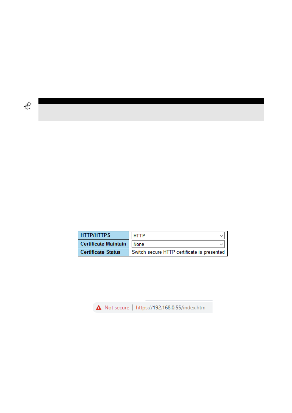
5.2 Access Control – Web Server HTTPS Configuration
HTTP/HTTPS - Controls whether the unit embedded web server should operate in HTTP or HTTPS
mode. HTTPS uses TLS v1.2 encryption to encry pt all Web network traffic between the user web
browser and the unit Web Server.
Figure 5-1: Web Server HTTP/HTTPS Configuration
Certificate Maintain – This option offers the administrator to manage the unit web-server’s self-signed
or CA signed certificate, used by web clients to verify if the unit web site is legit. Adding such a
certificate into the unit should eliminate the browser warning message, which recommends to the user
to avoid browsing to the unit.
Figure 5-2: Unsecure HTTPS browsing warning
The following certificate management options are available:
• None: No action (default).
• Delete: Delete the certificate being used by the Web Server. Since HTTPS cannot operate
without a certificate, this option can be executed only when the Web Server is configured as
HTTP Web Server.
Microsemi PDS-408G Web Management User Guide Ver. 1.0.1, 03-2019 32
Page 33

Access Control Access Control – Telnet/SSH/Web
NOTE:
• Generate: Generate a new self-signed certificat e required for HTTPS Web Server operation.
Please note that a self-signed certificate will cause a web browser warning requesting user
permission to add an exception to the web browser security protection policy, before browsing
to the unit.
• Upload: Upload a PEM certificate file. The possible met hods are: use a web browser for
uploading a certificate from your local driv e, or a URL for uploading a certificate over HTTP,
HTTPS, TFTP, FTP.
NOTE – Please refer to document 06-0013-021 for information on how to ge n e r ate and maintain
Self-Signed, CA-Signed certificates
5.3 Access Control – Telnet/SSH/Web
Authentication Method Configuration - Configures which network interface such as telnet, SSH, Web
or a local console should be enabled or disable, and how the remote user username + password will be
authenticated. Should it be done locally by the uni t or by remote RADIUS/TACACS+ authentication
server.
Accounting Method Configuration - Configures if the unit should send A cc ounting messages to
remote TACACS+ Accounting server whenev er a remote user logs in / logs out, and report any CLI
command typed by the user over Console, Telnet or SSH.
Figure 5-3: Access Control – Telnet/SSH/Web
5.3.1 Authentication Method Configuration
Every one of the management interfaces (console, Telnet, SSH, web) has 3 optional authentication
services going from left to right. If the 1
authentication service will be used instead, and the same for 3
authentication services are unreachable.
Microsemi PDS-408G Web Management User Guide Ver. 1.0.1, 03-2019 33
st
remote authentication service cannot be reached then t he 2nd
rd
in case both the 1st and the 2nd
Page 34

Access Control Access Control – Telnet/SSH/Web
NOTE:
Figure 5-4: Authentication Example
In the example above the user username + password authentication is processed as follows:
• Console: The username and password are processed localy based on the unit configuration.
• Telnet: Telnet is disabled (no Telnet)
• SSH: The remote SSH username + password authe ntication will be done by a remote Radius
Server. In case the Radius Server is down (no reply), then TACACS+ authentication server will
be used instead. In case TACACS+ Server is als o down (no reply) then it will be tested against
the unit local configuration.
• Web: The remote web username + password authentication will be done by a remote Radi u s
Server. In case the Radius Server is down (no reply), then TACACS+ authentication server will
be used instead. In case TACACS+ server is als o down, then the user will be rejected.
NOTE – RADIUS, TACACS+ configuration is done from in other pages.
5.3.2 Accounting Method Configuration
Any activity on any of the text-based interface (Console, Telnet, SSH) has the option to be reported and
logged to an Accounting TACACS+ Server
Figure 5-5: Accounting Method Configuration example
The user can configure that any login/logout or any command being typed will be reported to TACACS+
Accounting Server (the same used for remote user aut hentication). Same for any CLI command typed
by the user.
Microsemi PDS-408G Web Management User Guide Ver. 1.0.1, 03-2019 34
Page 35

Access Control Access Control – Access Cont rol List
5.4 Access Control – Access Control List
The access control list allows the user to configure from what IP range the remote user will be able to
access the Switch management interface over the web, SNMP, and Tel net/SSH. Up to 16 entries can
be added to the Access Control List table.
Figure 5-6: Access Control List
5.5 Access Control – View ACL Statistics
This page tracks the number of packets used to acce ss the Switch management interface whenever the
Access Control List is enabled. This report may hel p, for example, to identify an external use r t ry i ng to
hack the unit by reporting the number of discarded pa ck ets, etc.
Figure 5-7: View ACL Statistics
Microsemi PDS-408G Web Management User Guide Ver. 1.0.1, 03-2019 35
Page 36

VLAN General
NOTE:
Destinat io n MAC
6 BYTE
Source MAC
6 BYTE
802.1Q Header
4 BYTE
Payload
TPI D
2-BY TE
0x8100
VLAN-ID
2-BY TE
1-4095
Destinat io n MAC
6 BYTE
Source MAC
6 BYTE
802.1Q Header
4 BYTE
Payload
TPI D
2-BY TE
0x88A8
VLAN-ID
2-BY TE
1-4095
802.1Q Header
4 BYTE
TPI D
2-BY TE
0x8100
VLAN-ID
2-BY TE
1-4095
C-Tag
S-Tag
6 VLAN
6.1 General
• VLAN Access - VLAN is a mean to split Switch po rt s into support groups while each group is
totally isolated from the other as if we are using two or m ore independent Switches. Such
splitting is done by assigning different VLAN-IDs to various groups of ports, each group is
assigned a different VLAN-ID and the ports for each group are configured as Access ports,
meaning that VLAN tagging and port splitting is done i nternally by the switch. The packets
transmitted over the Access ports are the normal Ethernet ports with no VLAN tagging.
• VLAN Trunk – VLAN Trunk port configuration allow s multiple VLAN-IDs to transfer over the
same Ethernet cable or local LAN network with ab solute separation between the VLANs
transferring over the same infrastructure. A good analogy will be a highway with several lanes
having physical separation between each lane, preventing from a car to switch lanes although
all the cars are traveling from one side of the highway to the other.
6.1.1 Supported VLAN types
The switch supports single 802.1Q VLAN tagging and double 802.1Q VLAN tagging also known as
QinQ or 802.1ad. Switch ports with no external VLA N tagging are referred to as Access-Ports. Switch
Ports with external single VLAN tagging are referred to as Trunk C-Ports (C=customer VLAN). Ports
with double VLAN tagging are referred to as Trunk S-Ports (S=Service VLAN), as an internet service
provider may encapsulate customer VLAN on top of it s own VLAN, resulting in double VLAN tagging.
6.1.2 VLAN typing syntax
6.2 VLAN – Configuration
Figure 6-1: single and double VLAN tagging packet format
Individual VLAN elements are separated by commas. Ranges are specified with a dash separating the
lower and upper bound. The following example 1,10-13,200,300 will create VLANs 1, 10, 11, 12, 13,
200, and 300.
The VLAN configuration page consists of a global section and per port VLAN configuration.
NOTE – The next section contains se veral VLAN configuration examples which should make
VLAN configuration understanding easier.
Microsemi PDS-408G Web Management User Guide Ver. 1.0.1, 03-2019 36
Page 37

VLAN VLAN – Configuration
Term
Description
Ingress
Received packet
Egress
Transmitted packet
TPID = Tag
The first two out of four-byte of VLAN tagging. Typically, it should be 0x8100 followed
Valid VLAN-ID numbers range from 1-4095. VLAN-ID number 0, also known as VLAN
VLAN
VLAN-ID #0 used typically by VoIP system to mark VoIP priority packets
Native VLAN
Packet with no VLAN tagging
C-Tag
Customer VLAN-ID tag.
Service provider
Figure 6-2: VLAN configuration (global plus per-port)
6.2.1 Switch VLAN Terminology - explained
The table below attempts to simplify some of the V LAN terminology used in this chapter. To simplify
term description, some configuration parameter s will be used with real values rather than using their
general term.
Protocol
Identifier
Valid VLANID range
Priority Tag
by additional two-byte VLAN-ID. In case of Q-in-Q 802.1ad double VLAN tagging it
should be 0x88A8
Priority Tag is an exception. It is used typically by VoIP systems to prioritize VoI P traffic
over regular data traffic.
VLAN tag is made of four bytes. 1st two bytes=0x8100 followed by customer VLAN-ID
tag)
encapsulation of original
S-Tag
customer C-Tag VLAN-ID
with another VLAN-ID
named S-Tag. Double
Microsemi PDS-408G Web Management User Guide Ver. 1.0.1, 03-2019 37
Page 38

VLAN VLAN – Configuration
Term
Description
VLAN encapsulation
Allowed
Switch port in Trunk or Hybrid mode can be configured to
The figure to the right highlights in green
Used to connect between Switches. May use multiple VLANs
Switch Port
- Access Mode
- Por t V LAN= 5
-Rx N ative
-Rx P riorit y-VLAN
-Rx VLAN-5
-Tx N ativ e
tagging is also referred as
Q-in-Q or 802.1ad
VLANs/
Forbidden
VLANs
- Mode =
Trunk
- Mode =
Hybrid
Switch port
config
AccessMode
- Port
VLAN=5
discard packets from specific VLAN-IDs, and must be
configured to accept the VLAN-IDs in use.
the VLAN configuration parameters to be
set when configuring Switch ports to
Access mode. Please verify that Port
VLAN-ID is included in the Allowed
Access Vlans configuration field VLANs
list.
Used usually to connect end devices
Receive native VLAN packets (no
VLAN)
Receive Priority VLAN (VLAN-0)
packets
Receive VLAN packets with VLAN-ID
same as Access VLAN-ID (VLAN-5 as
in this example)
Transmit only native VLAN packets
(removes the VLAN-ID tag - no VLAN)
between Switches
Egress Tag configuration parameter = untag Port VLAN
o Rx native VLAN (no VLAN) as VLAN-5
Switch port
config
Trunk-Mode
o Rx VLAN priority tag (VLAN-0) as VLAN-5
o Tx tag all packets except VLAN-5. For example, a packet
received from another port configured as Access P ort VLAN-
- Port
5, will be transmitted untagged.
VLAN=5
Egress Tag configuration parameter = Tag All
o Rx native VLAN (untagge d pac ket s) is discarded.
o Rx VLAN priority tag (VLAN-0) is discarded.
o Tx all packets as VLAN tagged
Microsemi PDS-408G Web Management User Guide Ver. 1.0.1, 03-2019 38
Page 39

VLAN VLAN – Configuration
Term
Description
Hybrid-Mode is an extension of Trunk-Mode. T he di fference between Hybrid-Mode and
In Hybrid mode it is possible to enable/disable Rx packets
NOTE:
configured as Hybrid Unaware.
Ports in Trunk and Hybrid mode may control the tagging of frames on
NOTE:
On ingress (Rx), all frames (whether carrying a VLAN tag or not) are cl assified to the
Switch port
On ingress (Rx), frames with a VLAN tag with TPID = 0x8100 are classified to the
Hybrid-Mode
(general)
Hybrid
Ingress (Rx)
Filtering
Hybrid/Trunk
Egress (Tx)
Tagging
- Port
VLAN=5
Trunk-Mode is more configuration changes of additional parameters as Port-Type,
Ingress-Filtering, etc. (described in more detail below).
filtering based on VLAN header presence. The following
options are available:
Tagged and Untagged: accept both tagged and
untagged frames.
Tagged Only: accept only tagged frames. Discard
Untagged frames.
Untagged Only: accept only untagged frames.
Ingress filter is inactive (accept all) when the port is
Discard Tagged frames.
egress.
Untag Port VLAN: Remove VLAN tagging only for port VLAN
(VLAN-5 in this example). Leave all other VLAN tags
unchanged. This apply to both VLAN TPID 0x88A8 and 0x8100.
.
Tagged All: all frames, whether classified to the Port VLAN
(VLAN-5) or not, are transmitted with a tag.
Untagged All (only Hybrid mode): All frames, whether classified
to the Port VLAN (VLAN-5) or not, are transmitted without a tag
VLAN double tagging will become single tagged.
Switch port
Port
config
Hybrid-Mode
- Port Type=
Unaware
- Port
VLAN (VLAN-5 in this example). Possible tags are not removed on egress (Tx).
Rx tags all incoming packets as VLAN-5 even if Rx packet is already tagged. In
case packet is tagged with TPID=0x8100, it will be 0x8100 double tagged.
For example Rx packet with VLAN-10 will become 0x8100, 0x0005,0x8100,0x000A
VLAN=5
config
Hybrid-Mode
- Port Type=
C-Port
- Port
VLAN=5
Microsemi PDS-408G Web Management User Guide Ver. 1.0.1, 03-2019 39
TX does not untag any transmitted packet
VLAN ID
embedded in the tag. If a frame is untagged or priority tagged, the frame gets classified.
Rx path:
o Rx VLAN-2 (an example), Tx to another Trunk po rt as V LAN-2, also any
Access Port VLAN-2.
Page 40

VLAN VLAN – Configuration
Term
Description
o Rx native (no VLAN tag), Tx to another Trunk port as VLAN-5 (port V LAN), also
Switch port
On ingress (Rx), frames with a VLAN tag with TPID = 0x8100 or 0x88A8 are classified
Switch port
Same as for Hybrid S-Port except that the user may configure custom TPID different
any Access port configured as VLAN-5.
o Rx priority tagged (VLA N-0), Tx to another Trunk port as VLAN-5 (port VLAN),
also any Access port configured as VLAN-5.
o Rx from another Acces s port
TX path:
o TX does not untag any transmitted packets. However, it may untag Tx packet if
its VLAN-ID is the same as Port-VLAN (VLAN-5 in this example) and EgressTagging was set to Untag Port VLAN (packet will be sent as native VLAN –
untagged).
config
Hybrid-Mode
- Port Type=
S-Port
to the VLAN-ID embedded in the tag (first VLAN-ID in case of Q-in-Q double tagging).
If a frame is untagged (no VLAN) or priority tagged (VLAN-0), the frame gets classified
to Port VLAN (VLAN-5 in this example). If frames must be tagged on egress (Tx), they
will be tagged with an S-tag 0x88A8.
- Port
VLAN=5
config
Hybrid-Mode
- Port Type=
S-Custom-
than 0x88A8 by customizing global VLAN configuration parameter Ethertype for
Custom S-ports.
Port
Table 6-1: VLAN terminology explained
6.2.2 Global VLAN Configuration
Allowed Access VLANs - This field shows the allowed Access VLANs. This field affects only ports
configured as Access ports. Ports in other modes are members of all VLANs specified in the Allowed
VLANs field. By default, only VLAN 1 is enabled. More VLANs may be created by using a list syntax
where the individual elements are separated by commas. Ranges are specified with a dash separating
the lower and upper bound.
The example bellow will create VLANs 1,2,3,10. S paces are allowed in between the delimiters.
Figure 6-3: VLAN Global configuration
Ethertype for Custom S-ports – TPID value (specified in hexadecimal ) used for Q-in-Q 802.1ad
double VLAN tagging as described in the image bellow. The default value is 0x88A8, and it applies to
all ports whose Port Type is set to S-Custom-Port.
Microsemi PDS-408G Web Management User Guide Ver. 1.0.1, 03-2019 40
Page 41

VLAN VLAN – Configuration
6.2.3 Port VLAN Configuration
Figure 6-4: VLAN 802.1ad Q-in-Q double VLAN tagging
Figure 6-5: Port VLAN configuration
Port: Switch Ethernet port number
Mode: The Mode field controls the basic VLAN functionality of the port mode (defaul t is Access). A port
can be configured to one out of three modes as desc ribed below. Whenever a particular mode is
selected, the remaining Page fields for that port will be either grayed out or changeable depending on
the mode being configured. Grayed out fields sho w the value that the port will get when the appropriate
mode will be applied.
• Access: Access ports are normally used to connect end devices which are VLAN unaware.
Access ports have the following characteristics:
o Member of exactly one VLAN as configured in t he Port VLAN field. Default Access VLAN is 1
o Accepts untagged and C-tagged frames.
o Discards all frames that are not classified to the Access VLAN.
o On egress all frames are transmitted untaggedץ
• Trunk: Trunk ports can carry traffic of multiple VLANs simultaneously. Trunk mode is usually in
use whenever there is a need to connect one Switch using multiple VLANs to another Switch.
Trunk ports have the following characteristics:
o By default, a trunk port i s member of all VLANs (1-4095) unless defined otherwise by an
Allowed VLANs field. In this case none members VL ANs are discarded.
o By default, all frames except frames classified to the Port VLAN (also called as Native VLAN)
get tagged on egress. Frames classified to the Port VLAN do not get C-tagged on egress.
o Egress tagging can be changed to tag all frames, in which case only tagged f rames are
accepted on ingress.
Microsemi PDS-408G Web Management User Guide Ver. 1.0.1, 03-2019 41
Page 42

VLAN VLAN – Configuration
NOTE:
• Hybrid: Hybrid ports are very similar to Trunk ports with the following extra features:
o Can be configured to be VLA N t ag unaware, C-tag aware, S-tag aware, or S-custom-tag aware.
o Ingress filtering can be controlled.
o Ingress acceptance of frames and configuration of egress tagging can be configured
independently.
Port VLAN: configure port VLAN ID (also named as PVID).
Valid VLAN values range from 1-4095,
with the default value being 1.
On ingress, frames get classified to the Port VLAN. If the port is configured as VLAN unaware,
the frame is untagged, or VLAN awareness is enabled on the port, but the frame is priority
tagged (VLAN ID = 0).
On egress, frames classified to the Port VLAN do not get tagged if Egress Tagging
configuration is set to untag Port VLAN. The Port VLAN is called an "Access VLAN" for ports
in Access mode and Native VLAN for ports in Trunk or Hybrid mode.
Port Type: Ports in hybrid mode allow for changing the port type, i.e., whether a frames VLAN
tag is used to classify the frame on ingress to a particular VLAN, and if so, which TPID it
reacts on. Likewise, on egress, the Port Type determines the TPID of the tag, if a tag is
required.
• Unaware: On ingress, all frames, whether carrying a VLA N t ag or not, get classified to the Port
• C-Port: On ingress, frames with a VLAN tag with TPID = 0x8100 get classified to the VLAN ID
• S-Port: On ingress, frames with a VLAN tag with TPI D = 0x8100 or 0x88A8 get classified to the
VLAN, and possible tags are not removed on egress.
embedded in the tag. If a frame is untagged or priority tagged, the frame gets classified to the
Port VLAN. If frames must be tagged on egress, they will be tagged with a C-tag.
VLAN ID embedded in the tag. If a frame is untagged or priority tagged, the frame gets
classified to the Port VLAN. If frames must be tagged on egress, t hey will be tagged with an Stag.
• S-Custom-Port: On ingress, frames with a VLAN tag with a TPID = 0x8100 or equal to the
Ethertype configured for Custom-S ports get classified to the V LA N ID embedded in the tag. If
a frame is untagged or priority tagged, the frame gets classified to the Port VLAN. If frames
must be tagged on egress, they will be tagged with the custom S-tag.
Ingress Filtering: Hybrid ports allow for changing ingress fi l tering. Access and Trunk ports always have
ingress filtering enabled. If ingress filtering is enabled (checkbox is checked), frames classif i ed to a
VLAN that the port is not a member of get discarded. If i ngres s f i l tering is disabled, frames classified to
a VLAN that the port is not a member of are accepted and forwarded to the switch engine. However, the
port will never transmit frames classified to VLANs that it is not a member of.
The Ingress filter is inactive (accept all ) when the port is configured as Hybrid Unaware.
Ingress Acceptance: Hybrid ports allow for changin g t he t ype of frames that are accepted on ingress.
• Tagged and Untagged: Both tagged and untagged frames are a ccepted.
• Tagged Only: Only tagged frames are accepted on ingress. Untagged frames are discarded.
• Untagged Only: Only untagged frames are accepted on ingress. Tagged frames are
discarded.
Microsemi PDS-408G Web Management User Guide Ver. 1.0.1, 03-2019 42
Page 43

VLAN VLAN - View Members
Egress Tagging: Ports in Trunk and Hybrid mode may cont rol the tagging of frames on egress.
• Untag Port VLAN: Frames classified to the Port VLAN are t ransmitted untagged. Other frames
are transmitted with the relevant tag.
• Tag All: All frames, whether classified to the Port VLAN or not, are trans m i tted with a tag. This
option is only available for ports in Hybrid mode.
Allowed VLANs: Ports in Trunk and Hybrid mode may control which VLANs they are allowed to
become members of. Access ports can only be member of one VLAN, the Access VLAN. The fields
syntax is identical to the syntax used in the Enabled VLANs field. By default, a Trunk or Hybrid port will
become member of all VLANs, and is therefore set to 1-4095. The field may be left empty, which means
that the port will not become member of any VLANs .
Forbidden VLANs: A port may be configured to never be memb er of one or more VLANs. This is
particularly useful when dynamic VLAN protocols li ke MVRP and GVRP must be prevented from
dynamically adding ports to VLANs. The trick is to mark such VLANs as forbidden on the port in
question. The syntax is identical to the syntax used in the Enabled VLANs field. By default, t he fiel d i s
left blank, which means that the port may become a member of all possible VLANs.
6.3 VLAN - View Members
This page displays which VLAN-IDs are linked to which Switch Et hernet ports.
Figure 6-6: VLAN Membership Status
Microsemi PDS-408G Web Management User Guide Ver. 1.0.1, 03-2019 43
Page 44

VLAN VLAN – View Ports
6.4 VLAN – View Ports
This page displays a summary of all ports VLAN configuration
Figure 6-7: VLAN Port Status for Combined users
Microsemi PDS-408G Web Management User Guide Ver. 1.0.1, 03-2019 44
Page 45

PoE-BT Power General PoE background
Poe-PD
Maximum allocated
PoE-BT
PoE-AT
PoE-AF
0
15.4 (same as class-3)
Yes
Yes
Yes 1 4
Yes
Yes
Yes
2 7 Yes
Yes
Yes 3 15.4
Yes
Yes
Yes
4
30
Yes
Yes
--- 5 45
Yes
---
---
6
60
Yes
---
--- 7 75
Yes
---
---
8
90
Yes
---
---
7 POE-BT POWER
7.1 General PoE background
PoE-BT (IEEE 802.3-bt) is the latest PoE (Power Over Ethernet) specification offering up to 90[W] of
power whenever power is delivered over all four RJ45 cable pairs. PoE-BT is backwards compat ibl e
with PoE-AT (IEE 802.3at) offering up to 30W over two out of four cable pairs of the RJ45 connector.
PoE-BT is also backwards compatible with the first PoE specificati on known as PoE-AF (IEEE 802.3af)
capable of delivering up to 15W on two out of four cable pai rs inside the RJ45 connector.
The maximum power offered for each PD (Powered device) as Access Point, IP-Cameras, etc. is
determined by each PD classification named Class. T he S witch detects the PoE class advertised by
every PD and allocates Maximum-Power for each port accordingly.
Class
Table 7-1: PoE maximum power[W] per PD advertised class
Power [W] by the
Switch
support
Support
Support
Microsemi PDS-408G Web Management User Guide Ver. 1.0.1, 03-2019 45
Page 46

PoE-BT Power PoE-BT - Set PoE-BT Power
7.2 PoE-BT - Set PoE-BT Power
All PoE configuration, both global and per port is ca rried out from this page.
Figure 7-1: PoE-BT configuration
7.2.1 Global Configuration
Extended Power Mode – When checked, any PD device on any one of the ports may consume slightly
extra power beyond class maximum power (for example, 93W instead of 90W). Whenever PoE PD
device tries to consume power beyond its class max power, it will be shut down by the unit.
Uninterruptable Power – When checked (checked by default), the Switch is prevented from
performing a PoE power down and up cycle as part of the Switch’s startup process. This is applicable
only whenever the Switch is performing software reset, meaning uninterruptable AC power during the
entire software reset cycle.
7.2.2 Global Configuration
Figure 7-2: PoE Port Configuration
Port – Switch port number. Only PoE capable ports are listed (ports 9-11 are none PoE).
Enable – Enable/Disable POE power. Please note that the E thernet port will remain active even when
PoE port is disabled.
PoE Mode
• 802.3BT: Powers only PoE-BT/PoE-AT/PoE-AF compliant PD (powered device) devices.
Microsemi PDS-408G Web Management User Guide Ver. 1.0.1, 03-2019 46
Page 47
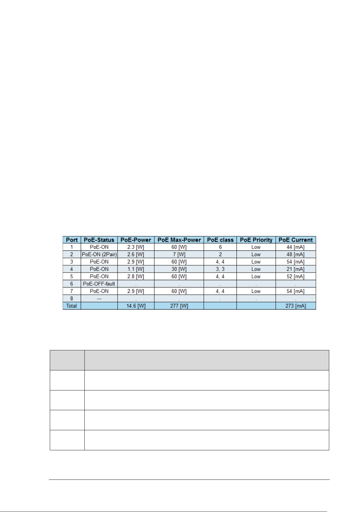
PoE-BT Power PoE-BT - View PoE-BT
PoE
Description
PoE
PoE power was disabled. However, the switch port remains opera tional as long it is
---
PoE is enabled, and no PoE device was detected. This is the normal PoE port state for
PoE-ON
PoE PD device was detected and power is delivered by the Switch to the PD device.
PoE-ON
PoE PD device was detected and power is delivered by the Switch to the PD device.
• Legacy: Powers PoE-BT/PoE-AT/PoE-AF compliant devices and PD (powered devi ces), which
may not be fully compliant PD devices. Use this option whenev er the Switch fails to power a
PD device because of PD not fully PoE compliant.
Priority – This parameter assigns the priority for a PD device connected to t he Switch port over other
PDs connected to the same Switch. This parameter will affect Switch PoE power delivery whenever
Switch total power capacity becomes lower than the overall actual power consumption of all PDs. In
such a scenario the Switch will have to shut down already powered PD device to let other POE devices
continue to work uninterrupted.
Also during power up, PDs with higher priority will be powered first. As a result, PDs with lo wer priority
may not be powered at all in case the already powered P Ds consume already the total Switch PoE
power capacity. There are three priority levels – Low, High, Critical.
• Low: The lowest PoE PD capacity. By default, all PoE port s are config to low priority.
• High: Higher priority than Low.
• Critical: Highest PoE port priority
Terminal Type/Description - a text string used to describe the PoE PD device. It has no effect on PoE
functionality.
7.3 PoE-BT - View PoE-BT
This page displays PoE status for all Switch PoE ports.
Port - Switch port number. Only PoE-capable ports are listed (ports 9-11 are none PoE).
PoE-Status – The following PoE status
Status
disabled
connected to none PoE device (such as Laptop, etc.), and Ether net port is enabled.
Figure 7-3: PoE status
displays are available
unplugged Switch ports.
This is the normal state when a typical four pair PD is connected.
(2Pair)
Microsemi PDS-408G Web Management User Guide Ver. 1.0.1, 03-2019 47
However, the power is delivered on only two out of four Ethernet pairs of the RJ45 jack.
Page 48
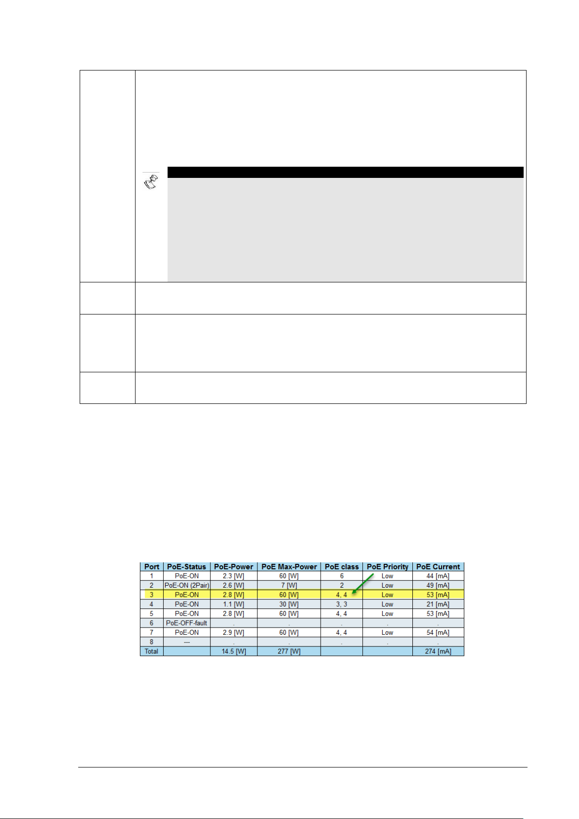
PoE-BT Power PoE-BT - View PoE-BT
PoE-OFF-
For PoE-PD device - Failure to deliver power to a PoE-PD device due to one of the
NOTE:
no Ethernet Link while the Laptop is in sleep mode.
No PoE
The software failed to detect PoE ICs. This message should not appear during normal
Detecting
The software is in the middle of the process to detect PoE ICs over I2C bus. This
PoE state
PoE initial state. This message should not appear during normal unit operation.
fault
IC
PoE
following reasons:
• Power limit exceeded - The overall power consumption including the port in fault
state, exceeds the maximum power the Power S upply can deliver.
• PoE-PD overload - The PD class requests more power than the port can deliver, so
the port PoE is down.
1. To minimize false fault displays, whenever the Ethernet Link port is On with PoE
power Off, it is safe to assume that the end device is a none PoE device such as a
PC, Laptop, etc. In this case although the PoE detection hardware detected PoEFault (and as a result PoE power is not applied – this is OK), it will be displayed as “-
--" meaning the POE is in search mode, looking for a valid PoE PD device to
connect.
2. However, there are exceptio ns which may cause PoE Fault to be reported. An
example to such an exception is a conn ected Laptop in sleep mode, since there is
unit operation.
message should not typically appear during normal operation. However, it may appear
for a very short time in case the user logs in to the uni t bef ore the entire software
initialization stage was completed.
unknown
Table 7-2: PoE Status
PoE Power – Reports PoE PD actual power consumption in Watt.
PoE Max-Power – Reports the maximum power in Watt that the PD device may consume. This value is
derived from PD class 0-8.
PoE Class - Displays the PoE PD class that the PD device is signaling to the Switch PoE port. Possible
values range from class 1-8 (class 0 is same as class 3). In case the PD hardware has double
independent class signature hardware (independent c l ass over each two out of four pairs) then two
class numbers will be reported as in the figure bellow.
Figure 7-4: PoE Class report
PoE Priority – Displays the PoE priority as it was configured by the user. For a more detailed
description please refer to the PoE Priority configuration description.
PoE – Reports the PoE current [mA] consumed by the PoE PD device.
Microsemi PDS-408G Web Management User Guide Ver. 1.0.1, 03-2019 48
Page 49

Spanning Tree - STP General
8 SPANNING TREE - STP
8.1 General
Spanning Tree Protocol (STP), and its variations as RSTP and MSTP, is used mainly for the following
reasons:
1. To prevent possible network loops, which without STP will cause broadcast storming.
2. Offer redundancy path from Switch to Switch or path t o path over multiple Switches by supporting
8.2 Spanning tree – Configuration - STP Config
network loops under the control of STP. The STP algorithm wil l m ake sure that at any given time
only one path out of multiple possible loops will be active, those allowing the Switch to use multiple
backup paths in case main connection path go down.
8.2.1 Basic Settings
Protocol Version -The MSTP/RSTP/STP protocol version setting. Valid values are STP, RSTP, and
MSTP.
Bridge Priority - Controls the bridge priority. Lower numeric values have better priority. The bri dge
priority plus the MSTI instance number, concatenated with the 6-byte MAC address of the switch forms
a Bridge Identifier. For MSTP operation, this is t he priority of the CIST. Otherwise, this is the priority of
the STP/RSTP bridge.
Forward Delay - The delay used by STP Bridges to transit Root and Designated Ports to Forwarding
(used in STP compatible mode). Valid values are in the range 4 to 30 seconds.
Max Age - The maximum age of the information transmitted by the Bridge when it is the Root Bridge.
Valid values are in the range 6 to 40 seconds, and MaxAge m ust be <= (FwdDelay-1)*2.
Maximum Hop Count - This defines the initial value of remai ning Hops for MSTI information generated
at the boundary of an MSTI region. It defines how ma ny bridges a root bridge can distribute its BPDU
information to. Valid values are in the range 6 to 40 hops.
Transmit Hold Count - The number of BPDUs a bridge port can send per second. When exceeded,
transmission of the next BPDU will be delayed. Vali d values are in the range 1 to 10 BPDUs per
second.
Figure 8-1: STP Configuration
Microsemi PDS-408G Web Management User Guide Ver. 1.0.1, 03-2019 49
Page 50
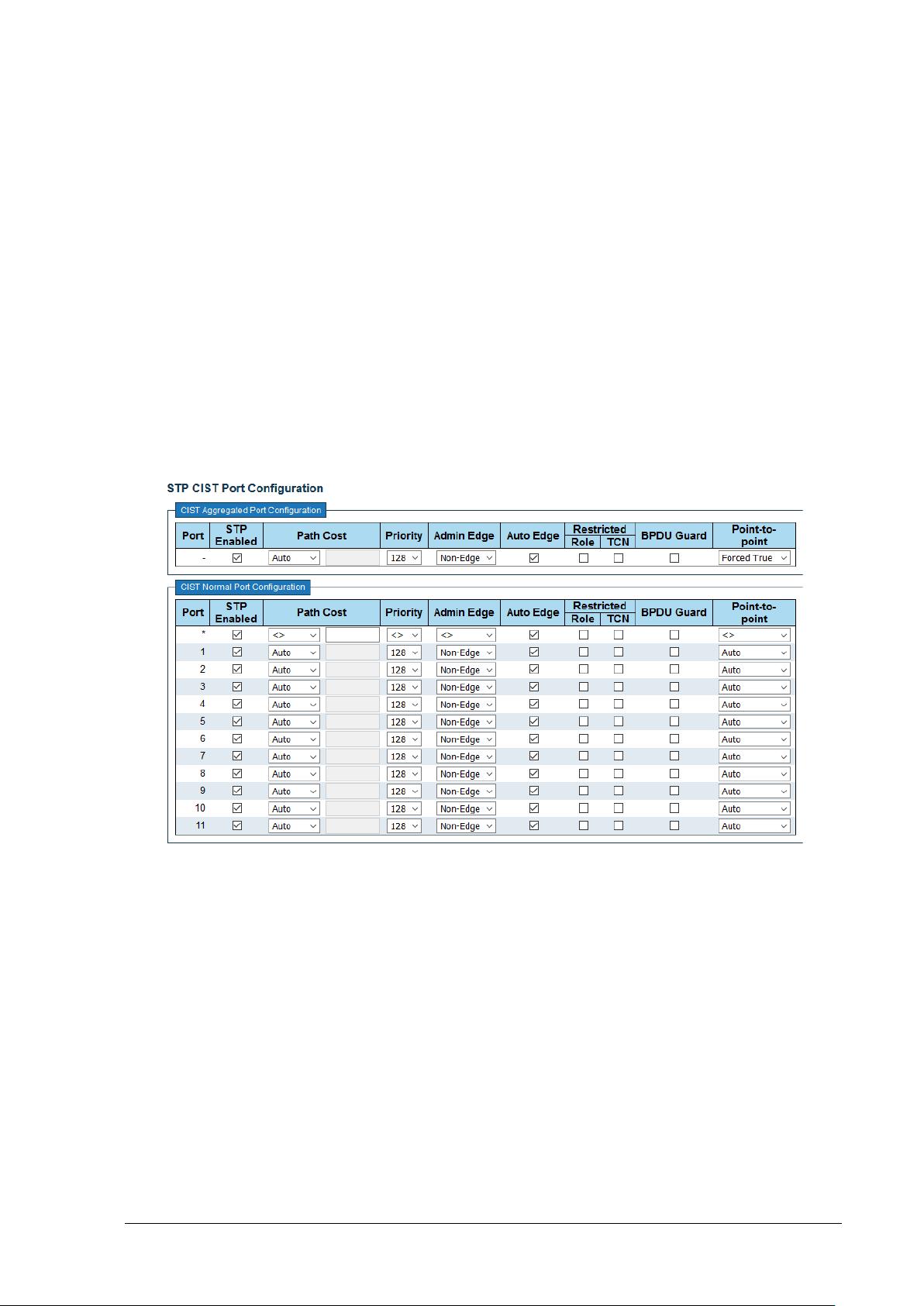
Spanning Tree - STP Spanning Tree – Configuration - STP Port Config
8.2.2 Advanced Settings
Edge Port BPDU Filtering - Controls whether a port is explicitly configured as Edge. It will transmit and
receive BPDUs.
Edge Port BPDU Guard - Controls whether a port is explicitly configured as Edge. It will disable itself
upon reception of a BPDU. The port will enter the error-disabled state and will be removed from the
active topology.
Port Error Recovery - Controls whether a port in the erro r-disabled state will be automatically enabled
after a certain time. If recovery is not enabled, port s have to be disabled and re-enabled for normal STP
operation. The condition is also cleared by a system reboot.
Port Error Recovery Timeout - The time to pass before a port in the err or-disabled state can be
enabled. Valid values are between 30 and 86400 seconds (24 hours).
8.3 Spanning Tree – Configuration - STP Port Config
This option allows you to inspect the current STP CI ST port configurations and change them. It contains
settings for physical and aggregated ports.
Figure 8-2: STP Port Configuration
Port - The switch port number of the logical STP port.
STP Enabled - Controls whether STP is enabled on this switch port.
Path Cost - Controls the path cost incurred by the port. The Auto setting will set the path cost as
appropriate by the physical link speed, using the 802.1D recommended values. Using the Specifi c
setting, a user-defined value can be entered. The path cost is used when establishing the active
topology of the network. Lower path cost ports are chosen as forwarding ports in favor of higher path
cost ports. Valid values are in the range 1 to 200000000.
Priority - Controls the port priority. This can be used to control priority of ports having identical port
cost. (See above). Lower priority is better.
operEdge (state flag) - Operational flag describing whether the port is connecting directly to ed ge
devices. (No Bridges attached). Transition to the forwarding state is faster for edge ports (having
operEdge true) than for other ports. The value of t his f l ag i s based on AdminEdge and AutoEdge fields.
This flag is displayed as Edge in Monitor STP Detailed Bridge S tatus Spanning Tree.
Microsemi PDS-408G Web Management User Guide Ver. 1.0.1, 03-2019 50
Page 51

Spanning Tree - STP Spanning tree – View - STP Bridges
AdminEdge - Controls whether the operEdge flag should start as set or cleared. (The initial operEdge
state when a port is initialized).
AutoEdge -Controls whether the bridge should enable automatic edge detection on the bridge port.
This allows operEdge to be derived from whether BPDUs are received on the port or not.
Restricted Role - If enabled, causes the port not to be selected as Root Port for the CIST or any MSTI,
even if it has the best spanning tree priority vector. S uch a port will be selected as an Alternate Port
after the Root Port has been selected. If set, it can cause lac k of spanning tree connectivity. It can be
set by a network administrator to prevent bridges external to a core region of the network influence the
spanning tree active topology, possibly becaus e t hose bridges are not under the full control of the
administrator. This feature is also known as Root Gua rd.
Restricted TCN - If enabled, causes the port not to propagate received topology change notifi cat i ons
and topology changes to other ports. If set it can cause temporary loss of connectivity after changes in
a spanning trees active topology because of persistently incorrect learned station locat i on information. It
is set by a network administrator to prevent bridges external to a core region of the network, causing
address flushing in that region, possibly because those bridges are not under the full control of the
administrator or the physical link state of the att ached LANs transits frequently.
BPDU Guard - If enabled, causes the port to disable itself upon receiving valid BPDUs. Contrary to t he
similar bridge setting, the port Edge status does not affect this setting.
Point-to-Point - Controls whether the port connects to a point-to-point LAN rather than to a shared
medium. This can be automatically determine d, or f orced either true or false. Transition to the
forwarding state is faster for point-to-point LANs t han for shared media.
8.4 Spanning tree – View - STP Bridges
This page provides a status overview of all STP bridge instan ces. The displayed table contains a row
for each STP bridge instance.
Figure 8-3: View STP Bridges
MSTI - The Bridge Instance. This is also a link to the STP Det ai l ed Bridge Status as described below.
8.4.1 STP Detailed Bridge Status
• Bridge Instance - The Bridge instance - CIST, MST1, ...
Microsemi PDS-408G Web Management User Guide Ver. 1.0.1, 03-2019 51
Figure 8-4: View STP Detailed Bridge Status
Page 52

Spanning Tree - STP Spanning tree – View - STP Bridges
• Bridge ID - The Bridge ID of this Bridge instance.
• Root ID - The Bridge ID of the currently electe d root bridge.
• Root Port - The switch port currently assigned the root port role.
• Root Cost - Root Path Cost. For the Root Bridge this is zero. For all other Bridges, it is the sum
of the Port Path Costs on the least cost path to the Root Bridge.
• Regional Root - The Bridge ID of the currently elected regional root bridge, inside the MSTP
region of this bridge. (For the CIST instance only).
• Internal Root Cost - The Regional Root Path Cost. For the Regional Root Bridge this is zero.
For all other CIST instances in the same MSTP region, it is the sum of the Internal Port Path
Costs on the least cost path to the Internal Root Bridge. (For the CIST instance only).
• Topology Flag -The current state of the Topology Change Flag of this Bridge instance.
• Topology Change Count - The number of times where t he topology change flag has been set
(during a one-second interval).
• Topology Change Last - The time passed since the Topology Flag was last set.
8.4.2 CIST Ports & Aggregation State
• Port - The switch port number of the logical STP port.
• Port ID - The port id as used by the STP protocol. This is the priority part and the logical port
index of the bridge port.
• Role - The current STP port role. The port role can be one of t he following values:
o AlternatePort
o BackupPort
o RootPort
o DesignatedPort
• State - The current STP port state. The port state can be one of the following val ues: Discarding
Learning Forwarding.
• Path Cost - The current STP port path cost. This will either be a value computed from the Au to
setting, or any explicitly configured value.
• Edge - The current STP port (operational) Edge Flag. An Edge Port is a switch port to which no
Bridges are attached. The flag may be automatically computed or explicitly configured. Each Edge
Port transits directly to the Forwarding Port S tate, since there is no possibility of it participating i n a
loop.
• Point-to-Point - The current STP port point-to-point flag. A point-to-point port connects to a non-
shared LAN media. The flag may be automatically computed or explicitly configured. The point-topoint properties of a port affect how fast it can transit to STP state.
• Uptime - The time since the bridge port was last initialized.
Bridge ID -The Bridge ID of this Bridge instance.
Root ID - The Bridge ID of the currently elected root bridge.
Microsemi PDS-408G Web Management User Guide Ver. 1.0.1, 03-2019 52
Page 53

Spanning Tree - STP Spanning Tree - View - STP Port Status
Root Port - The switch port currently assigned the root port role.
Root Cost - Root Path Cost. For the Root Bridge it is zero. For all other Bridges, it is the sum of the
Port Path Costs on the least cost path to the Root Bridge.
Topology Flag - The current state of the Topology Change Flag of this Bridge instance.
Topology Change Last - The time since last Topology Change occurred.
8.5 Spanning Tree - View - STP Port Status
This page displays the STP CIST port status for physical ports of the switch
Figure 8-5: View STP Port Status
Port - The switch port number of the logical STP port.
CIST Role - The current STP port role of the CIST port. The port role can be one of the following
values:
• AlternatePort
• BackupPort
• RootPort
• DesignatedPort
• Disabled.
CIST State - The current STP port state of the CIST port. The port state can be one of the following
values: Discarding Learning Forwarding.
Uptime - The time since the bridge port was last i ni t i alized.
8.6 Spanning Tree - View - STP Port Statistics
This option displays the STP port statistics counters of bridge ports in the switch. The STP port
statistics counters are described below.
Figure 8-6: View STP Port Statistics
Port - The switch port number of the logical STP port.
MSTP - The number of MSTP BPDUs received/transmitt ed on the port.
RSTP - The number of RSTP BPDUs received/transmitted on the port.
Microsemi PDS-408G Web Management User Guide Ver. 1.0.1, 03-2019 53
Page 54

Spanning Tree - STP Spanning Tree - View - STP Port Statistics
STP - The number of legacy STP Configuration BPDUs received/transmitted on the port.
Microsemi PDS-408G Web Management User Guide Ver. 1.0.1, 03-2019 54
Page 55

SNMP SNMP- Enable SNMP
NOTES:
default public, private community strings (passwords) prior enabling SNMPv2.
NOTES:
9 SNMP
1. Detailed SNMP configuration example can be found at the end of the SNMP section.
2. SNMP is disabled by default for security concerns. In case S NMPv2 is used, please change SNMPv2
9.1 SNMP- Enable SNMP
This page is responsible for enabling/disabling SNMP in general - SNMPv1, SNMPv2 and SNMPv3 and
also configure several SNMP MIB-II System-Information OiD
Figure 9-1: Enable SNMP
Enable SNMP – Enable/Disable SNMP in general (SNMP1, SNMPv2, SNMPv3).
System Contact – Textual identification of t he cont act person for this managed node. String length is 0
to 255, and valid ASCII characters range from 32 to 126.
System Name - An administratively assigned name for this managed node. By convention, this is the
nodes fully-qualified domain name. A domain name is a text string drawn from the alphabet (A-Z,a-z),
digits (0-9), minus sign (-). No space characters are permitted as part of a name. The first character
must be an alpha character. And the first or last character must not be a minus sign. The allowed string
length is 0 to 255.
1. The System Name field is also used as unit Hostname f or CLI / T el net/SSH interface.
2. The System Name field is also used by DHCP whenever t he host name within VLAN DHCP
configuration field is left blank.
System Location - The physical location of thi s unit. The allowed string length is 0 to 255, and the
allowed content is the ASCII characters from 32 to 126.
Microsemi PDS-408G Web Management User Guide Ver. 1.0.1, 03-2019 55
Page 56

SNMP SNMP- SNMPv2-v3 configuration
9.2 SNMP- SNMPv2-v3 configuration
Figure 9-2: SNMPv2-v3 Configuration
9.2.1 SNMP View OiD-Range Configuration
Configures which SNMP OiDs should be included/ excluded from the entire SNMP OiD tree.
Delete - Check to delete the entry. It will be deleted during the next save.
View Name - A string name identifying the view OiD branch to be included/excluded. The allowed string
length is 1 to 32, and the allowed content is ASCII characters from 33 to 126.
View Type - Indicates if the named OiD branch should be included/excluded from the entire MIB OiD
tree.
OID Subtree - The OID defining the root of the subtree to add to the named vi ew. The allowed OID
length is 1 to 128. The allowed string content is digital number or asterisk(*).
9.2.2 SNMP Community Configuration
Configures SNMP community table used as part of SNMP Group Configuration. Entry i ndex key is
Community name.
Delete - Check to delete the entry. It will be deleted during the next save.
Microsemi PDS-408G Web Management User Guide Ver. 1.0.1, 03-2019 56
Page 57

SNMP SNMP- SNMPv2-v3 configuration
Community Name - Indicates the security name to map the community to the SNMP Groups
configuration. The allowed string length is 1 to 32, and the allowed content is ASCII characters from 33
to 126.
Community secondsret - Indicates the community secret (a cc ess string) to permit access using
SNMPv1 and SNMPv2c to the SNMP agent. The allo wed string length is 1 to 32, and the allowed
content is ASCII characters from 33 to 126.
Source IP - Indicates the SNMP access source address. A particular range of source addresses can be
used to restrict source subnet when combined wit h source prefix.
Source Prefix - Indicates the SNMP access source address prefix.
9.2.3 SNMP Group Configuration
Configures SNMP group-name table based on secondsurity Model and secondsurity Name.
Delete - Check to delete the entry. It will be deleted during the next save.
secondsurity Model - Indicates the security model that this entry should belong to. Possible security
models are: SNMPv1, SNMPv2C, SNMPv3
V2 community / V3 user - SNMPv2: One of the security names from previous stage (SNMP
Community Configuration) that this entry should belong to.
SNMPv3: One of the SNMPv3 users that were already configured by the help of SNMPv3 Users page.
Group Name - A string identifying the group name that t hi s ent ry should belong to. The allowed string
length is 1 to 32, and the allowed content is ASCII characters from 33 to 126.
9.2.4 SNMP Access Configuration
Configures SNMP access table. The entry index key s are Group Name, secondsurity Model and
secondsurity Level.
Delete - Check to delete the entry. It will be deleted during the next save.
Group Name - One of the Group-Name strings that were confi gured by SNMP Group Configuration
table. The allowed string length is 1 to 32, and the all owed content is ASCII characters from 33 to 126.
secondsurity Model - Indicates the security m odel that this entry should belong to. Possible security
models are: Any, V1, V2c, V3
secondsurity Level - Indicates the security model that this entry should belong to. Possible securi t y
models are:
• NoAuth, NoPriv: No authentication and no privacy.
• Auth, NoPriv: Authentication and no privacy.
• Auth, Priv: Authentication and privacy.
Read View Name - The name of the MIB view defining the MIB obj ects for which this request may
potentially read OiD values.
Write View Name - The name of the MIB view defining the MIB object s f or which this request may
potentially set OiD new values.
Microsemi PDS-408G Web Management User Guide Ver. 1.0.1, 03-2019 57
Page 58

SNMP SNMP- SNMPv2-v3 configuration
9.2.5 SNMP- SNMPv3 Users Configuration
Configures SNMPv3 user table. The entry i ndex keys are Engine ID and User Name.
Figure 9-3: SNMPv3 User Configuration
Delete - Check to delete the entry. It will be deleted during the next save.
Engine ID - An octet string identifying the engine ID that this entry should belong to. The string must
contain an even number (in hexadecimal format) with number of digits between 10 and 64, but all-zeros
and all-Fs are not allowed. The SNMPv3 architecture uses the User-based secondsurity M o del (USM)
for message security and the View-based Access Control Model (VACM) for access control. For the
USM entry, the usmUserEngineID and usmUser Name are the entry keys. In a simple agent,
usmUserEngineID is always that agents own snmpEngineID value. The value can also take th e value of
the snmpEngineID of a remote SNMP engine with which this user can communicate. In other words, if
user engine ID equal system engine ID then it is local user; otherwise its remote user.
User Name - A string identifying the user name that t his entry should belong to. The allowed string
length is 1 to 32, and the allowed content is ASCII characters from 33 to 126.
secondsurity Level - Indicates the security model that this entry should belong to. Possible security
models are:
• NoAuth, NoPriv: No authentication and no privacy.
• Auth, NoPriv: Authentication and no privacy.
• Auth, Priv: Authentication and privacy.
The value of security level cannot be modified if entry al ready exists. That means it must first be
ensured that the value is set correctly.
Authentication Protocol - Indicates the authentication protocol that this entry should belong to.
Possible authentication protocols are:
• None: No authentication protocol.
• MD5: An optional flag to indicate that this user uses MD5 authentication protocol.
• SHA: An optional flag to indicate that this user uses SHA authentication protocol. The
value of the security level cannot be modified if an entry already exists. That means must first
ensure that the value is set correctly.
Authentication Password - A string ident i f ying the authentication password phrase. For MD5
authentication protocol, the allowed string length is 8 to 32. For SHA authentication protocol, the
allowed string length is 8 to 40. The allowed content is ASCII characters from 33 to 126.
Privacy Protocol - Indicates the privacy protocol that this entry should belong to. Possible privacy
protocols are:
• None: No privacy protocol.
• DES: An optional flag to indicate that this user uses DES authentication protocol.
• AES: An optional flag to indicate that this user uses AE S authentication protocol.
Microsemi PDS-408G Web Management User Guide Ver. 1.0.1, 03-2019 58
Page 59

SNMP SNMP- Trap Configuration
Privacy Password - A string identifying the privacy password phrase. The allowed string length is 8 to
32, and the allowed content is ASCII characters f rom 33 to 126.
9.3 SNMP- Trap Configuration
Provides a summary of the already configured SNMP Trap Servers, with the option to add/delete
remote SNMP trap Servers.
9.3.1 SNMP Trap Server List
Delete - Check to delete the entry. It will be deleted during the next save.
Name - Every raw at the table has its own unique name.
Enable - Offers the option to keep SNMP Trap-Server record inside the table without necessary
sending SNMP Trap to the SNMP Trap Server.
• Enabled: Send SNMP Trap to the IP address of the remote SNMP Trap-Server.
• Disabled: Keep SNMP Trap-Server record, without sending any traps to it.
Version - Indicates the type of SNMP trap version should be sent. T he following options are available:
• SNMPv1: Send SNMP trap in SNMPv1 format.
• SNMPv2c: Send SNMP trap in SNMPv2c format.
• SNMPv3: Send SNMP trap in SNMPv3 format.
Destination Address - IPv4 or IPv6 or hostname (for example: my.server.com) address of remote
SNMP Trap-Server. Valid hostname should be made of alphabet ( A-Za-z), digits (0-9), dot (.), dash (-).
Spaces are not allowed.
The first character must be an alpha character, and t he first and last characters must not be a dot or a
dash.
Figure 9-4: SNMP Trap Configuration
Destination port - Indicates the SNMP trap UDP destination port. The default value should be UDP
port 162. Valid UDP port range is 1~65535.
Microsemi PDS-408G Web Management User Guide Ver. 1.0.1, 03-2019 59
Page 60

SNMP SNMP- Configuration exampl e
9.3.2 SNMP Trap Source Configuration
Provides a list for all the events that may cause SNMP trap to be sent.
Delete - Check to delete the entry. It will be deleted during the next save.
Name - Indicates the name of the event that will case SNMP trap to be sent. Possible options are:
• coldStart: Unit up after power was applied to the unit.
• warmStart: SNMP was enabled in run time
• linkUp: Ethernet Link is up.
• linkDown: Ethernet Link is down
• authenticationFailure: Remote SNMP client was trying to access the unit using invalid
username/pass values.
• newRoot: MSTP Spanning Tree Root was changed.
• topologyChange: network topology was changed.
• lldpRemTablesChange:
9.4 SNMP- Configuration example
9.4.1 SNMPv2 Configuration Example
Enabling SNMP is the only step required to enable SNMPv2 with default SNMPv2 configurat i on (using
public/private community strings). The example bellow uses slightly different configuratio n st rings for
better description of the procedure to conf igure SNMPv2.
• Use default (.1) to allow the user access to all
SNMP OiD or create your own SNMP View
OiD-Range, limiting the user access to
specific OiD. In the example the user has
access to all SNMP OiD except for MIB-II
system branch .1.3.6.1.2.1.1
• Modify/create public/private community
strings. Please note that the
Community name field is just a
reference to the Community
secondsret password field
• Modify/create two groups
using SNMPv2c security
model and link them to the
community name created in
the previous step.
Microsemi PDS-408G Web Management User Guide Ver. 1.0.1, 03-2019 60
Page 61

SNMP SNMP- Configuration exampl e
• Modify/create Access configuration list to the groups created in the previous step.
9.4.2 SNMPv3 Configuration Example
• Configure SNMPv3 user
• Remove SNMPv1, v2 from
“group configuration”
• Add SNMPv3 security
model, and assign to it a
group name
• Add to “ANMP Access
Configuration” the group
name from previous stage,
with security Level of
SNMPv3, and assign to it
the desired read/write
options
Microsemi PDS-408G Web Management User Guide Ver. 1.0.1, 03-2019 61
Page 62

RADIUS, TACACS+ General
NOTE:
method located under: Access ControlTelnet/SSH/Web
10 RADIUS, TACACS+
10.1 General
RADIUS (Remote Authentication Dial-In User Servic e) and TACACS+ (Terminal Access Controller
Access Control System) are networking protocols that provide centralized Authentication, Authoriz ation,
and Accounting (AAA or Triple A) management for users who connect to the unit over Web, telnet,
SSH. The remote username and password are sent to RADIUS/TACACS+ Server for aut hentication
(user + password match/do not match) and authorization
locally using unit local configuration file.
(privilege level) rather than being tested
RADIUS/TACACS+ configuration only will have no effect on remote user authentication over
Web, Telnet, SSH. To complete the configuration user must configure also authentication
10.1.1 General - Authentication, Access-Level terminology
• Authentication - Remote username and password is sent t o RA DIUS-Server for authentication
instead of tested locally by the unit. The RADIUS-Server determines if remote user should be
accepted or rejected.
• Access-Level - Remote user access-level i s det ermined by the RADIUS-Server. For normal
unit operation, all remote users should obtain access level 15 (administrator) by remote
RADIUS-Server.
10.1.2 General - Setting up remote RADIUS Server
• Successful RADIUS Server configuration must i nclude two steps. The first step is to configure
RADIUS Server to acknowledge remote user username and password. The second step is
configuring the RADIUS Server so that RADIUS-Server Access-Accept reply message will
include AVP (Attribute value Pair) number 26 with the st ring priv-lvl=15, assigning admin (15)
privilege level to the user. Successful Radius-Server Access-Accept reply lacking the attribute
number 26 with the mentioned string will assign user privilege level number 1 out of 15 with no
ability to do any changes inside the unit.
• Configuring Free-Radius users.conf configuration file:
Change users.conf as follows:
username Cleartext-Password := "pass"
Cisco-AVPair += "priv-lvl=15"
Microsemi PDS-408G Web Management User Guide Ver. 1.0.1, 03-2019 62
Page 63

RADIUS, TACACS+ RADIUS TACACS+ - Configuration - RADIUS
10.2 RADIUS TACACS+ - Configuration - RADIUS
Figure 10-1: RADIUS Configuration
10.2.1 Global Configuration
The global configuration section contains all RADIUS default values to be used whenever a user adds
new RADIUS-Server and leaves ident ical fields blank.
• Timeout - Timeout is the number of seconds, in the range 1 to 1000, to wait for a reply from a
RADIUS server before retransmitting the request.
• Retransmit - Retransmit is the number of tim es, i n the range 1 to 1000, a RADIUS request is
retransmitted to a server that is not responding. I f the server has not responded after the last
retransmit it is considered to be dead.
• Deadtime - Deadtime, which can be set to a number b et ween 0 to 1440 minutes, is the period
during which the switch will not send new requests t o a server that has failed to respond to a
previous request (dead). This should stop the switch from continually trying to contact a server
that it has already determined as dead. Setting the Dead ti me to a value greater than 0
(zero) will enable this feature , but only if more than one server has been configured.
• Change secondsret Key - Specify to change the secret key or not. When "Yes" is selected for
the option, you can change the secret key - up to 63 characters long - shared between the
RADIUS server and the switch.
10.2.2 Server Configuration
• Delete - Check this box to delete a RADIUS serve r entry. The entry will be deleted during the
next Save.
• Hostname - The IPv4/IPv6 addressor hostname of the RADIUS server.
• Auth Port - The UDP port to use on the RADIUS server for authenti cat i on. S et to 0 to disable
authentication.
• Timeout - This optional setting overrides the global timeout value. Leaving it blank will use the
global timeout value.
• Retransmit - This optional setting overrides the global retransmit value. Leaving it blank will
use the global retransmit value.
Microsemi PDS-408G Web Management User Guide Ver. 1.0.1, 03-2019 63
Page 64

RADIUS, TACACS+ RADIUS TACACS+ - Configuration – TACACS+
NOTE:
• Change secondsret Key - Specify to change the secret key or not. When the checkbox is
checked, you can change the setting overrides t he global key. Leaving it blank will use the
global key.
10.3 RADIUS TACACS+ - Configuration – TACACS+
Figure 10-2: TACACS+ Configuration
10.3.1 Global Configuration
The global configuration section contains all TACA CS+ default values to be used whenever a user adds
new TACACS+ Server and leaves identical fiel ds blank.
• Timeout - Timeout is the number of seconds, in the range 1 to 1000, to wait for a reply from a
TACACS+ server before it is considered to be dead.
Setting the Deadtime to a value greater t han 0 (zero) will enable this feature, but only if more
than one server has been configured
• Deadtime - Deadtime, which can be set to a number between 0 to 1440 minutes, is the period
during which the switch will not send new requests to a server that has failed to respond to a
previous request (dead). This should stop the switch from continually trying to contact a server
that it has already determined as dead.
• Change secondsret Key - Specify to change the secret key or not. When "Yes" is selected,
you can change the secret key - up to 63 characters long - shared between the TACACS+
server and the switch.
10.3.2 Server Configuration
• Delete - Check this box to delete a TACACS+ serve r entry. The entry will be deleted during the
next Save.
• Hostname - The IPv4/IPv6 addressor hostname of the TACACS+ server.
• Port - The TCP
port to use on the TACACS+ server for authentication.
• Timeout - This optional setting overrides the global timeout value. Leaving it blank will use the
global timeout value.
• Change secondsret Key - Specify to change the secret key or not. When the checkbox is
checked you can change the setting overrides the global key. Leaving it blank will use the
global key.
Microsemi PDS-408G Web Management User Guide Ver. 1.0.1, 03-2019 64
Page 65

RADIUS, TACACS+ RADIUS TACACS+ - View – RADIUS Status
NOTE:
10.4 RADIUS TACACS+ - View – RADIUS Statu s
This Page provides an overview of the status of the RADIUS servers that were configured. Pressing on
the RADIUS Server index number will show detai l ed statistics for this specific RADIUS Server.
• # - Press the index number (1-5) for a detailed RADIUS status statistics report.
• IP Address - The IP address of the RADIUS Server that was configured.
• Authentication Port - The RADIUS Server UDP port number used for authentication.
• Authentication Status - The current status of the RADIUS server. This field takes one of the
following values:
o Disabled - RADIUS server is disabled.
o Not Ready - RADIUS server is enabled, but IP communication is not yet up and running.
o Ready - RADIUS server is enabled, IP communication is up and running, and the
RADIUS module is ready to accept access attempts.
o Dead (X seconds left) - RADIUS-Server fails to reply to authentication requests (timeout) and
was placed in Dead state for Dead-time minutes. This should speed up future remote user
access by skipping on timeout x retry waiting delay (in seconds) before switching to next
(backup) Radius-Server. The Server will be re-enabled after dead-time expires.
Dead state is applicable only wh en t here is more than one RADIUS-server, and dead-time time
value is greater than 0
Microsemi PDS-408G Web Management User Guide Ver. 1.0.1, 03-2019 65
Page 66
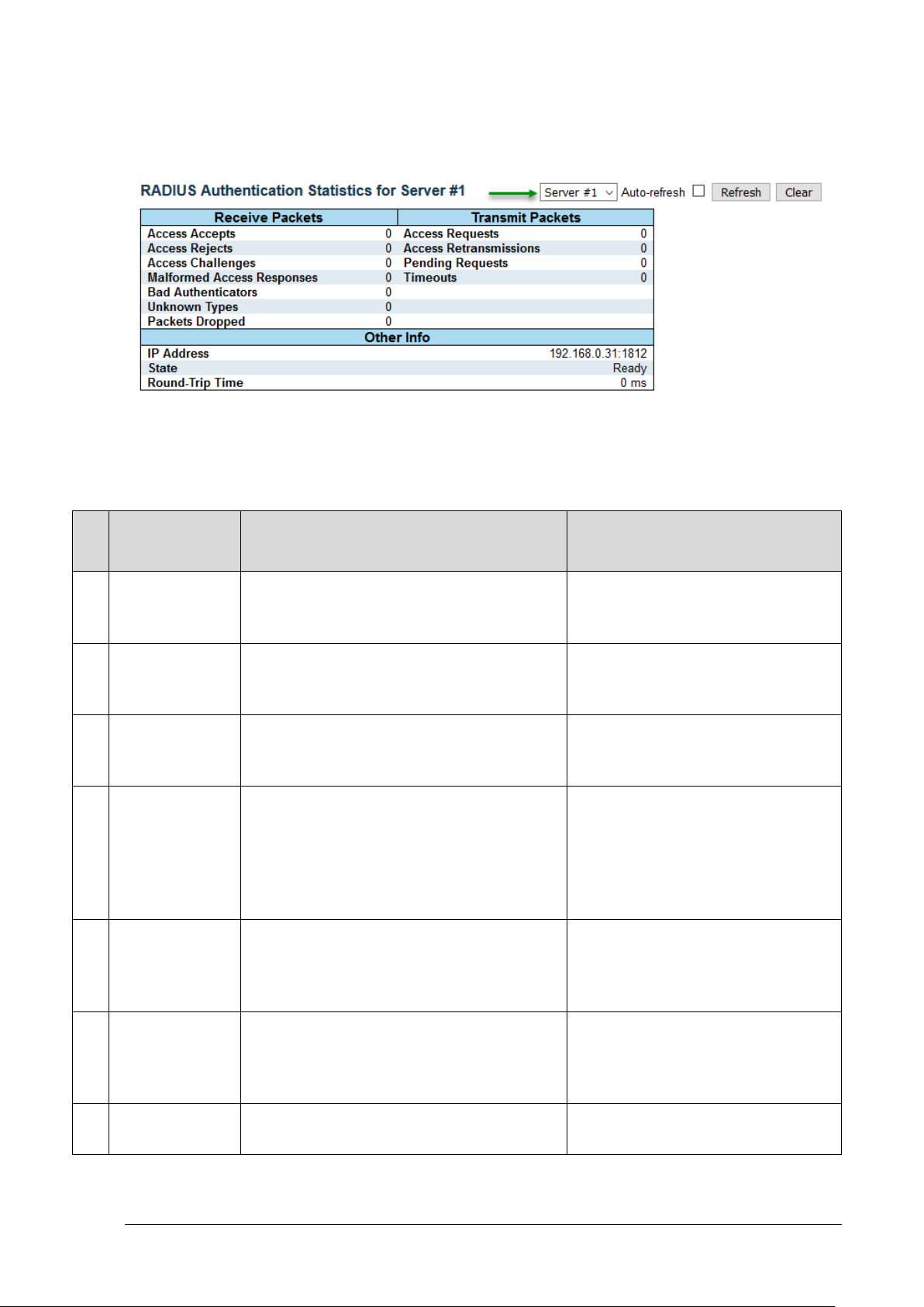
RADIUS, TACACS+ RADIUS TACACS+ - View – RADIUS Details
Tx
RADIUS Access-Accept packets
RADIUS Access-Reject packets
RADIUS Access-Challenge packets
RADIUS malformed Access-
RADIUS Access-Response packets
RADIUS packets that were received
Packets
10.5 RADIUS TACACS+ - View – RADIUS Detai ls
This page provides detailed statistics for a particular RADIUS server.
Figure 10-3: RADIUS Authentication Statistics
10.5.1 Packet Counters
Name RFC4668 Name Description
Rx
Access Accepts radiusAuthClientExtAccessAccepts
(valid or invalid) received from the
server.
Rx Access Rejects radiusAuthClientExtAccessRejects
(valid or invalid) received from the
server.
Rx
Rx
Access
Challenges
Malformed
Access
Responses
radiusAuthClientExtAccessChallenges
radiusAuthClientExtMalformed
AccessResponses
(valid or invalid) received from the
server.
Response packets received from the
server. Malformed packets include
packets with an invalid length. Bad
authenticators or Message
Authenticator attributes.
Bad
Rx
Authenticators
radiusAuthClientExtBadAuthenticators
containing invalid authenticators or
Message Authenticator
attributes received from the server.
Rx Unknown Types radiusAuthClientExtUnknownTypes
Rx
Dropped
Microsemi PDS-408G Web Management User Guide Ver. 1.0.1, 03-2019 66
radiusAuthClientExtPacketsDropped
with unknown types from the server
on the authentication port and
dropped.
RADIUS packets that were received
from the server on the authentication
Page 67

RADIUS, TACACS+ RADIUS TACACS+ - View – RADIUS Details
Tx
port and dropped for some other
RADIUS Access-Request packets
RADIUS Access-Request packets
RADIUS Access-Request packets
RADIUS authentication timeouts to
The time interval (mseconds)
Name RFC4668 Name Description
Rx
reason.
Access
Tx
Requests
Access
Tx
Retransmissions
Pending
Tx
Requests
radiusAuthClientExtAccessRequests
radiusAuthClientExtAccessRetransmissions
radiusAuthClientExtPendingRequests
Tx Timeouts radiusAuthClientExtTimeouts
sent to the server. This does not
include retransmissions.
retransmitted to the RADIUS
authentication server.
destined for the server that have not
yet timed out or received a response.
This variable is incremented when an
Access-Request is sent and
decremented due to receipt of an
Access-Accept,
Access-Reject, Access-Challenge,
timeout, or retransmission.
the server. A retry to the same server
is counted as a
retransmit as well as a timeout. A
send to a different server is counted
as a Request as well as a timeout.
Round-Trip
--Time
Table 10-1: Packet Counters
radiusAuthClientExtRoundTripTime
between the most recent AccessReply/Access-Challenge and the
Access-Request
that matched it from the RADIUS
authentication server. The granularity
of this measurement is 100
ms. A value of 0 ms indicates that
round-trip communication hasn’t
been established with the server yet.
Microsemi PDS-408G Web Management User Guide Ver. 1.0.1, 03-2019 67
Page 68

RADIUS, TACACS+ RADIUS TACACS+ - View – RADIUS Details
Name
Description
IP
IP address and UDP port for the RADIUS-server.
State
The current status of the RADIUS server. This fiel d takes one of the following values:
10.5.2 Other Info (RADIUS-Server IP address and state)
Address
Disabled: RADIUS server is disabled.
Not Ready: RADIUS server is enabled, but IP communication is not yet up and running.
Ready: RADIUS server is enabled, IP communication is up a nd running, and the
RADIUS module is ready to accept access attempts.
Dead (X seconds left): RADIUS-Server failed to reply t o aut hentication requests
(timeout) and was placed in Dead state for Dead-ti m e minutes. This should speed up
future remote user access by skipping on timeout x ret ry waiting delay (in seconds)
before switching to next (backup) Radius-Server. The Server will be re-enabled after
dead-time expires.
NOTE: Dead state is applicable only when there is m ore than one RADIUS-server, and
dead-time time value is greater than 0.
Table 10-2: Other Info
Microsemi PDS-408G Web Management User Guide Ver. 1.0.1, 03-2019 68
Page 69

Aggregation/LACP General
11 AGGREGATION/LACP
11.1 General
The Aggregation feature allows the user to configure aggregation as static, group and dynamic by using
LACP.
11.2 Aggregation/LACP – Aggregation – Aggregation Configuration
Figure 11-1: Aggregation Configuration
11.2.1 Aggregation Group Configuration
Group ID - Indicates the aggregation group ID for the settings contained in the same row. Group ID
"Normal" indicates there is no aggregation. Only one group ID is valid per port.
Port Members - Each switch port is listed for each group ID. B y default, no ports belong to any
aggregation group.
• Only full duplex ports can join an aggregation
• The ports in each group must be in the same speed .
Mode - This parameter determines the mode for t he aggregation group.
• Disabled: The group is disabled.
• Static: The group operates in static aggregation mode.
• LACP (Active): The group operates in LACP acti ve aggregation mode. See IEEE 801.AX-
2014, section 6.4.1 for details.
• LACP (Passive): The group operates in LACP passiv e aggregation mode. See IEEE 801.AX-
2014, section 6.4.1 for details.
Revertive - This parameter only applies to LACP-enabled groups. It determines if the group will perform
automatic link (re-)calculation when links with higher priority becom e available.
Max Bundle - This parameter only applies to LACP-enabl ed groups. It determines the maximum
number of active bundled LACP ports allowed in an a ggregation.
Microsemi PDS-408G Web Management User Guide Ver. 1.0.1, 03-2019 69
Page 70
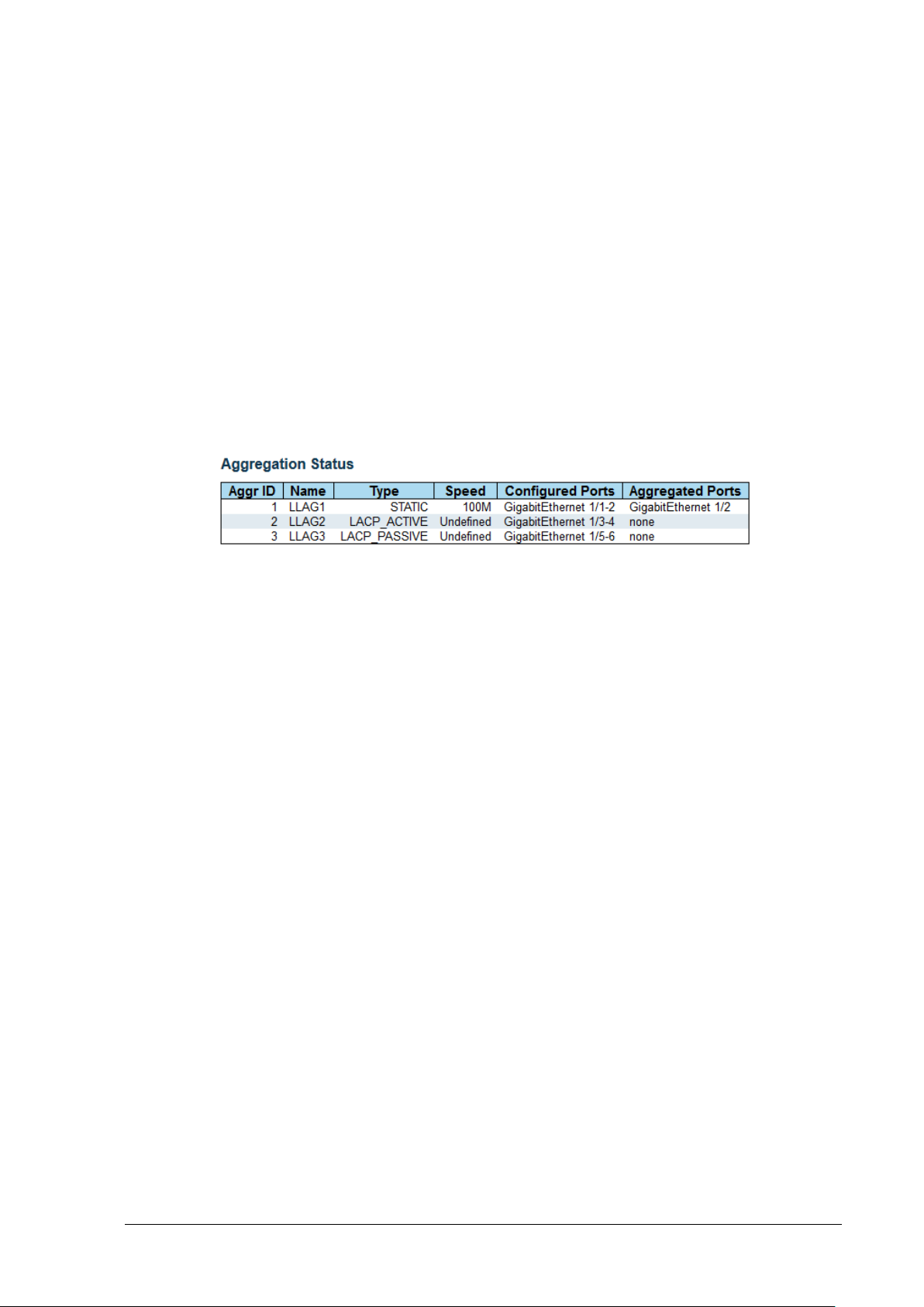
Aggregation/LACP Aggregation Status
11.2.2 Hash Contributors Configuration
• Source MAC Address - The Source MAC address can be used to calculate the destination
port for the frame. Check to enable the use of the Source MAC address, or uncheck to disable.
By default, Source MAC Address is enabled.
• Destination MAC Address - The Desti nation MAC Address can be used to calculate the
destination port for the frame. Check to enable the u se of the Destination MAC Address, or
uncheck to disable. By default, Destination MAC Address is disabled.
• IP Address - The IP address can be used to calculate the destination port for the frame. Check
to enable the use of the IP Address, or uncheck to disable. By default, IP Address is enabled.
• TCP/UDP Port Number - The TCP/UDP port number can be used to calculate the destination
port for the frame. Check to enable the use of the TCP/UDP Port Number, or uncheck to
disable. By default, TCP/UDP Port Number is enabled.
11.3 Aggregation Status
Figure 11-2: Aggregation Status
• Aggr ID - The Aggregation ID associated with this aggregation instance.
• Name - Name of the Aggregation group ID.
• Type - Type of the Aggregation group (Static or LACP).
• Speed - Speed of the Aggregation group.
• Configured ports - Configured member ports of the Aggregation group.
• Aggregated ports - Aggregated member ports of the Aggregation group.
Microsemi PDS-408G Web Management User Guide Ver. 1.0.1, 03-2019 70
Page 71
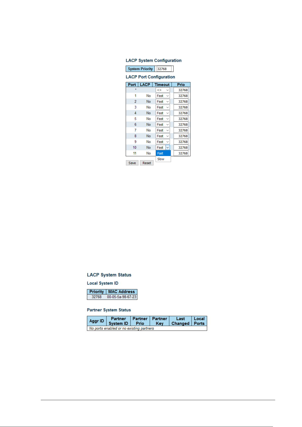
Aggregation/LACP Aggregation/LACP - LACP- Configure LACP
11.4 Aggregation/LACP - LACP- Configure LACP
Figure 11-3: LACP Configuration
• Port - The switch port number.
• LACP - Show whether LACP is currently enabl ed on this switch port.
• Timeout - The Timeout controls the period between BPDU transmissions. Fast will transmit
LACP packets each second, while Slow will wait for 3 0 seconds before sending a LACP
packet.
• Prio - The Priority controls the priority of the port, range 1-65535. If the LACP partner wants to
form a larger group than is supported by this device t hen t hi s parameter will control which ports
will be active and which ports will be in a backup role. Lower number means greater priority.
11.5 Aggregation/LACP – LACP – View – System Status
This Page provides a status overview for the system-level LACP information.
Figure 11-4: View LACP System Status
Microsemi PDS-408G Web Management User Guide Ver. 1.0.1, 03-2019 71
Page 72

Aggregation/LACP Aggregation/LACP – LACP – View – Internal Status
11.5.1 Local System ID
This table displays both the local system priority and the local system MAC address which forms the
local LACP System ID.
11.5.2 Partner System Status
This table display the partner system information f or each LACP aggregation group.
Aggr ID - The Aggregation ID associated with this aggregation instance.
• Partner System ID - The system ID (MAC address ) of the aggregation partner.
• Partner Prio - The priority that the partner has assigned to this aggregation ID.
• Partner Key - The key that the partner has assigned to this aggregation ID.
• Last changed - The time since this aggregation changed.
• Local Ports - Shows which ports are a part of this aggregati on for this switch.
11.6 Aggregation/LACP – LACP – View – Internal Status
This Page provides a status overview for the LACP internal (i.e. local system ) status for all ports. Only
ports that are part of an LACP group are shown.
Figure 11-5: View LACP Internal Port Status
• Port - The switch port number.
• State - The current port state:
• Down - The port is not active.
• Active - The port is in active state.
• Standby - The port is in standby state.
• Key - The key assigned to this port. Only port s wit h the same key can aggregate together.
• Priority - The priority assigned to this aggregation group.
• Activity - The LACP mode of the group (Active or Passive).
• Timeout - The timeout mode configured for the port (Fast or Slow).
• Aggregation - Shows whether the system con siders this link to be "aggregateable"; i.e., a
potential candidate for aggregation.
• Synchronization - Shows whether the system considers this link to be "IN_SYNC"; i.e., it has
been allocated to the correct LAG, the group has been associated with a compatible
Aggregator, and the identity of the LAG is consistent with the System ID and operational Key
information transmitted.
• Collecting - Shows if collection of incoming frames on this link is enabled.
• Distributing - Shows if distribution of outgoing frames on this link is enabl ed.
Microsemi PDS-408G Web Management User Guide Ver. 1.0.1, 03-2019 72
Page 73

Aggregation/LACP Aggregation/LACP – LACP – View – Neighbor Status
• Defaulted - Shows if the Actors Receive machine i s using Defaulted Operational Partner
information.
• Expired - Shows if that the Actors Receive machine is in the EXPIRED state.
11.7 Aggregation/LACP – LACP – View – Neighbor Status
This page provides a status overview for the LACP neighbor status f or al l ports. Only ports that are part
of an LACP group are shown
Figure 11-6: View LACP Neighbor Port Status
• Port - The switch port number.
• State - The current port state:
• Down - The port is not active.
• Active - The port is in active state.
• Standby - The port is in standby state.
• Aggr ID - The aggregation group ID which the port is assigned to.
• Partner Key - The key assigned to this port by the partner.
• Partner Port - The partner port number associated with this link.
• Partner Port Priority - The priority assigned to this partner port .
• Activity - The LACP mode of the group (Active or Passive).
• Timeout - The timeout mode configured for the partner port (Fast or Slow).
• Aggregation - Shows whether the partner conside rs this link to be "aggregateable"; i.e., a
potential candidate for aggregation.
• Synchronization - Shows whether the partner considers this link to be " IN_SYNC"; i.e., it has
been allocated to the correct LAG, the group has been associated with a compatible
Aggregator, and the identity of the LAG is consistent with the System ID and operational Key
information transmitted.
• Collecting - Shows if collection of incoming frames on this link is enabled.
• Distributing - Shows if distribution of outgoing frames on this link is enabl ed.
• Defaulted - Shows if the partners Receive machine is using Defaulted Operational Partner
information.
• Expired - Shows if that the partners Receive machine is in the EXPIRED state.
Microsemi PDS-408G Web Management User Guide Ver. 1.0.1, 03-2019 73
Page 74

Aggregation/LACP Aggregation/LACP – LACP – View – Port Statistics
11.8 Aggregation/LACP – LACP – View – Port Statistics
This page provides an overview for LACP statistics for all ports.
Figure 11-7: View LACP Port Statistics
• Port - The switch port number.
• LACP Received - Shows how many LACP frames have been received at each port.
• LACP Transmitted - Shows how many LACP frames have been sent from each port.
• Discarded - Shows how many unknown or illegal L A CP frames have been discarded at each
port.
Microsemi PDS-408G Web Management User Guide Ver. 1.0.1, 03-2019 74
Page 75

LLDP LLDP – Configure LLDP
12 LLDP
12.1 LLDP – Configure LLDP
12.1.1 LLDP Parameters
• Tx Interval - The switch periodically transmits LLDP fram es to its neighbors to update the
network discovery information. The interval between the LLDP frames is determined by the Tx
Interval value. Valid values are restricted to 5 - 32768 seconds.
• Tx Hold - Each LLDP frame contains information t hat det erm ines how long the information in
the LLDP frame shall be considered valid. The LLDP information valid period is set to Tx Hold
multiplied by Tx Interval seconds. Valid values are restricted to 2 - 10 times.
• Tx Delay - If a configuration is changed (e.g. the IP address) a new LLDP frame is transmitted,
but the time between the LLDP frames will always be at least the value of Tx Delay seconds.
Tx Delay cannot be larger than 1/4 of the Tx Interval value. Valid values are restricted to 1 8192 seconds.
• Tx Reinit - When an interface is disabled, LLDP is disabled or the switch is rebooted, a LLDP
shutdown frame is transmitted to the neighboring units, signaling that the LLDP information is
not valid anymore. Tx Reinit controls the number of seconds between the shutdown frame and
a new LLDP initialization. Valid values are restrict ed to 1 - 10 seconds.
12.1.2 LLDP Interface Configuration
Figure 12-1: LLDP Configuration
• Interface - The name of the switch’s logical LLDP interface.
• Mode - Select LLDP mode.
o Rx only: The switch will not send out LLDP information, but LLDP information from neighbor
units is analyzed.
Microsemi PDS-408G Web Management User Guide Ver. 1.0.1, 03-2019 75
Page 76

LLDP LLDP – Configure LLDP
NOTE:
o Tx only: The switch will drop LLDP information received from neighbors, but will send out
LLDP information.
o Disabled: The switch will not send out LLDP information, and will drop LLDP information
received from neighbors.
o Enabled: The switch will send out LLDP information, and will analyze LLDP information
received from neighbors.
• CDP Aware - Select CDP awareness.
The CDP operation is restricted to decoding incoming CDP frames (The switch doesn’t transmit
CDP frames). CDP frames are only decoded if LLDP on the interface is enabled. Only CDP
TLVs that can be mapped to a corresponding field in the LLDP neighbors table are decoded.
All other TLVs are discarded (unrecognized CDP TLVs and discarded CDP frames are not
shown in the LLDP statistics.). CDP TLVs are mapped onto LLDP neighbors table as shown
below.
o CDP TLV "Device ID" is mapped to the LLDP "Chassis ID" field.
o CDP TLV "Address" is mapped to the LLDP "Management Address" fiel d. The CDP address
TLV can contain multiple addresses, but only the first address is shown in the LLDP neighbors
table.
o CDP TLV "Port ID" is mapped to the LLDP "Port ID" field.
o CDP TLV "Version and Platform" is mapped to the LLDP "System Description" field.
Both the CDP and LLDP support "system capabilit ies" , but t he CDP capabilities cover capabilities
that are not part of the LLDP. These capabilities are s hown as "others" in the LLDP neighbors
table.
If all interfaces have CDP awareness disabled, the switch forwards CDP frame s received from
neighbor devices. If at least one interface has CDP awar eness enabled all CDP frames are
terminated by the switch.
When CDP awareness on an interface is disabled, the CDP information is not removed
immediately, but gets removed when the hold time is exceeded
• Port Descr - Optional TLV: When checked the "port d escription" is included in LLDP
information transmitted.
• Sys Name - Optional TLV: When checked the "syst em name" is included in LLDP information
transmitted.
• Sys Descr - Optional TLV: When checked the " sy st em description" is included in LLDP
information transmitted.
• Sys Capa - Optional TLV: When checked the " sy st em capability" is included in LLDP
information transmitted.
• Mgmt Addr - Optional TLV: When checked the "management address" is included in LLDP
information transmitted.
Microsemi PDS-408G Web Management User Guide Ver. 1.0.1, 03-2019 76
Page 77

LLDP LLDP – View Neighbor Information
12.2 LLDP – View Neighbor Information
This Page provides a status overview for all LLDP neighbors. The displayed table contains a row for
each interface on which an LLDP neighbor is detected.
Figure 12-2: LLDP Neighbor
• Local Interface - The interface on which the LLDP frame was received.
• Chassis ID - The identification of the neighbo rs L LDP frames.
• Port ID - The identification of the neighbor port.
• Port Description - The port description advertised by the neighbor unit.
• System Name - The name advertised by the neighbor unit.
• System Capabilities - Describes the neighbor units capabilities. Enabled capability is f ol lowed
by (+) and disabled capability is followed by (-). The possible capabilities are:
o Other
o Repeater
o Bridge
o WLAN Access Point
o Router
o Telephone
o DOCSIS cable device
o Station only
o Reserved
• Management Address - The neighbor units address that i s us ed f or higher layer entities to
assist discovery by the network management. T his could for instance hold the neighbors IP
address.
Microsemi PDS-408G Web Management User Guide Ver. 1.0.1, 03-2019 77
Page 78

LLDP LLDP – View LLDP Status
12.3 LLDP – View LLDP Status
This page provides an overview of all LLDP traffic. Two types of counters are shown. Global counters
are counters that refer to the whole switch, while local counters refer to per interface counters for the
currently selected port.
12.3.1 Global Counters
• Clear global counters - If checked the global counters are cleared when is pressed.
• Neighbor entries were last changed - Shows the time when the last entry was deleted or
added. It also shows the time elapsed since the last change was detected.
• Total Neighbors Entries Added - Shows the number of new entr ies added since switch
reboot.
• Total Neighbors Entries Deleted - Shows the number of new entries deleted since switch
reboot.
• Total Neighbors Entries Dropped - Shows the number of LLDP frames dropped due to the
entry table being full.
• Total Neighbors Entries Aged Out - Shows the number of entries del et ed due to Time-To-
Live expiring.
12.3.2 Local Counters
• Local Interface - The interface on which LLDP frames are received or transmitted.
Figure 12-3: View LLDP Status
• Tx Frames - The number of LLDP frames transmitted on the interface.
• Rx Frames - The number of LLDP frames received on t he i nterface.
• Rx Errors - The number of received LLDP frames containing some kind of error.
• Frames Discarded - If an LLDP frame is received on a interface, and the switch’s internal table
has run full, the LLDP frame is counted and discarded. This situation is known as "Too Many
Neighbors" in the LLDP standard. LLDP frames require a new entry in the table when the
Microsemi PDS-408G Web Management User Guide Ver. 1.0.1, 03-2019 78
Page 79

LLDP LLDP – View LLDP Status
Chassis ID or Remote Port ID is not already contained within the table. Entries are removed
from the table when a given interfaces link is down, an LLDP shutdown frame is received, or
when the entry ages out.
• TLVs Discarded - Each LLDP frame can contai n m ultiple pieces of information, known as
TLVs (TLV is short for "Type Length Value"). If a T LV is malf ormed, it is counted and discarded.
• TLVs Unrecognized - The number of well-formed TLVs, but with an unknown type value.
• Org. Discarded - If LLDP frame is received wit h an organizationally TLV, but the TLV is not
supported the TLV is discarded and counted.
• Age-Outs - Each LLDP frame contains information about how long t i m e the LLDP information
is valid (age-out time). If no new LLDP frame is received within the age out t i m e, t he LLDP
information is removed, and the Age-Out counter is incremente d.
• Clear - If checked, the counters for the specific interface are cleared when
is pressed.
Microsemi PDS-408G Web Management User Guide Ver. 1.0.1, 03-2019 79
Page 80

Port Isolation Port Isolation – Configure Private VLAN
13 PORT ISOLATION
13.1 Port Isolation – Configure Private VLAN
13.1.1 General
Private VLAN has nothing to do with traditional VLANs, meaning that Private-VLAN ID can be
identical to VLAN-ID.
Private-VLAN filters outgoing destination port traffic. Packet received on port X can be sent only to
destination ports which are marked as part of port X group, considering multiple PVLAN-ID table
rows configuration (union).
Private-VLAN does not affect unit management over IP.
Example - PVLAN-ID2 = marked ports 1,5,6. PVLAN-ID3 = marked ports 1,6,8. All other ports are
unchecked.
As a result, ports-2,3,4,7,9,10,11 will not send any outgoing packets except for packets created
internally.
incoming traffic on port 1 will be sent only to ports 5,6,8.
Incoming traffic on port 5 will be sent only to ports 1,6.
Incoming traffic on port 6 will be sent to ports 1,5,8
Incoming traffic on port 8 will be sent to ports 1,6
Figure 13-1: Private VLAN Membership Configuration
13.1.2 Private VLAN - configuration parameters
• Delete - To delete a private VLAN entry, check thi s box. The entry will be deleted during the
next save.
• PVLAN ID - Indicates the ID of this Private-VLAN.
• Port Members - Used to show/select the unit Ethernet ports assigned to be members for this
specific Private-VLAN ID.
13.2 Port Isolation – Configure Port Isolation
13.2.1 General
Marked ports are prevented from sending packets to each other - isolated. However, they can
communicate normally with all the other Switch ports.
Example - Marking ports 1,2 will block any traffic from port 1 to reach to port 2 and vice versa.
However, each one of them can communicate normal ly with ports 3-11
Microsemi PDS-408G Web Management User Guide Ver. 1.0.1, 03-2019 80
Page 81

Port Isolation Port Isolation – Configure Port Isolation
Figure 13-2: Port Isolation Configuration
13.2.2 Port Isolation - configuration parameters
• Port Members - Select the ports that are not allowed to communicate with each other
(isolated).
Microsemi PDS-408G Web Management User Guide Ver. 1.0.1, 03-2019 81
Page 82

Loop Protection Loop Protection – Configure Protection
14 LOOP PROTECTION
14.1 Loop Protection – Configure Protection
This Page allows the user to inspect the current Loop Protection configurations, and change them if
needed.
14.1.1 General Settings
• Enable Loop Protection - Controls whether loop protections is enabled (as a whole).
• Transmission Time - The interval between each loop prote ct ion PDU sent on each port. Valid
values are 1 to 10 seconds. Default value is 5 seconds.
• Shutdown Time - The period (in seconds) for which a port will be k ept disabled in a loop is
detected (and the port action shuts down the port). Valid values are 0 to 604800 seconds (7
days). A value of zero will keep a port disabled (until next device restart). Default value is 180
seconds.
14.1.2 Port Configuration
• Port - The switch port number of the port.
• Enable - Controls whether loop protection is enabled on t his switch port.
• Action - Configures the action performed when a loop is detected on a port. Valid values are
Shutdown Port, Shutdown Port and Log or Log Only.
• Tx Mode - Controls whether the port is actively gene rating loop protection PDUs, or whether it
is just passively looking for looped PDUs.
Figure 14-1: Loop Protection Configuration
Microsemi PDS-408G Web Management User Guide Ver. 1.0.1, 03-2019 82
Page 83

IGMP Snooping General
15 IGMP SNOOPING
15.1 General
Snooping is the process of listening to IGMP (Interne t Group Management Protocol) network traffic to
control delivery of IP multicast packets. Network switches supporting IGMP snooping listen to IGMP
conversation between hosts and routers and maintain a map of the ports that the IP multicast traffic
should go through, while filter the IP multicast traffi c f rom other Switch ports which do not need those IP
Multicast packets, conserving bandwidth on t hose li nks.
15.2 IGMP Snooping – Configuration – Global Settings
15.2.1 IGMP Snooping Configuration
• Enable IGMP Snooping - Enable the Global IGMP Snooping.
• Unregistered IPMCv4 Flooding Enabled - Enable unregistered IPMCv4 traffic flooding. The
flooding control takes effect only when IGMP Snoopi ng is enabled. When IGMP Snooping is
disabled, unregistered IPMCv4 traffic flooding is always active despite this setting.
• IGMP SSM Range - SSM (Source-Specific Multicast) Range allows the SSM-aware hosts and
routers run the SSM service model for the groups in th e address range. Assign valid IPv4
multicast address as prefix with a prefix length (from 4 to 32) for the range.
• Leave Proxy Enabled - Enable IGMP Leave Proxy. This feature can be used to avoid
forwarding unnecessary leave messages to the router side.
• Proxy Enabled - Enable IGMP Proxy. This feature can be used t o avoid forwarding
unnecessary join and leave messages to the route r side.
Figure 15-1: IGMP Global Settings
Microsemi PDS-408G Web Management User Guide Ver. 1.0.1, 03-2019 83
Page 84

IGMP Snooping IGMP Snooping – Configuration – Enable per VLAN
15.2.2 Port Related Configuration
• Port - The switch port number of the port.
• Router Port - Specify which ports act as router port s. A router port is a port on the Ethernet
switch that leads towards the Layer 3 multicast device or IGMP Querier. If an aggregation
member port is selected as a router port, the whole a ggregation will act as a router port.
• Fast Leave - Enable the fast leave on the port. T he system will remove the group record and
stop forwarding data upon receiving the IGMP v2 leave message, without sending last member
query messages. It is recommended to enable thi s f eature only when a single IGMPv2 host is
connected to the specific port.
• Max multicast groups (Throttling) - Enable to limit the number o f multicast groups to which a
switch port can belong, ranging from 1,2,3…10, unlimited.
15.3 IGMP Snooping – Configuration – Enable per VLAN
The user may change IGMP Snooping computability ranging from IGMPv1-v3, Auto, set Querier, etc.
for the VLANs which is already configured. The page shows up to VLAN 99 entries sorted from lowest
highest VLAN-ID.
Figure 15-2: IGMP Snooping VLAN Configuration
15.3.1 IGMP Snooping Enable per VLAN
• VLAN ID - The VLAN ID of the entry.
• IGMP Snooping Enabled - Enable the per-VLAN IGMP Snooping. Up to 8 VLANs can be
selected for IGMP Snooping.
• Querier Election:
o Enable - When enabled, the unit will send every time interval IGMP Membership Query,
General packets, and as a result retrieve IGMP membership sent back from active
members. The reply packets from active members will cause the membership table to be
updated dynamically.
o Disable – Stops acting as IGMP Querier; do not send IGMP Membership Query packets and
clear members table.
• Querier Address – Configures the IPv4 source address being used when transmitting IGMP
Query packets.
o IPv4 address was set - Uses configured IPv4 Querier Address as the source address in all
transmitted IGMP Membership Query packets.
o 0.0.0.0 (not set) - uses VLAN IPv4 management address.
o 0.0.0.0 (not set) and no VLAN IPv4 management a dd ress – uses the first available IPv4
management address, and if there is no such IPv4 address, then uses 192.0.2.1 as default
IPv4 source IP address.
Microsemi PDS-408G Web Management User Guide Ver. 1.0.1, 03-2019 84
Page 85

IGMP Snooping IGMP Snooping – View – Groups Information
• Compatibility - Compatibility is maintained by hosts and routers taking appropriate actions
depending on the versions of IGMP operating on these hosts and routers within the network.
The available selection is IGMP-Auto, Forced IGMPv1, Forced IGMPv2, Forced IGMPv 3. The
default compatibility value is IGMP-Auto.
• PRI - Priority of Interface.
It indicates the IGMP control frame priority level generated by the system. These values can be
used to prioritize different classes of traffic. The allowed range is 0 (best effort) to 7 (highest),
the default interface priority value is 0.
• RV - Robustness Variable.
The Robustness Variable allows tuning for the expected packet loss on a network. The allowed
range is 1 to 255, the default robustness variable value i s 2.
• QI - Query Interval.
The Query Interval is the interval between the general queri es sent by the Querier. The allowed
range is 1 to 31744 seconds, the default query interval is 125 seconds.
• QRI - Query Response Interval.
The Maximum Response Delay is used to calculate the Maximum Response Code inserted into
the periodic General Queries. The allowed range is 0 to 31744 in tenths of seconds, the default
query response interval is 100 in tenths of seconds (10 seconds).
• LLQI (LMQI for IGMP) - Last Member Query Interval.
The Last Member Query Time is the time value represented by the Last Member Query
Interval, multiplied by the Last Member Query Count. The allowed range is 0 to 31744 in tenths
of seconds, the default last member query interval i s 10 in tenths of seconds (1 second).
• URI - Unsolicited Report Interval. The Unsolicited Report Interval is the time between
repetitions of a hosts initial report of membership i n a group. The allowed range is 0 to 31744
seconds; the default unsolicited report interval is 1 second.
15.4 IGMP Snooping – View – Groups Information
Figure 15-3: View IGMP Snooping Groups Information
15.4.1 IGMP Snooping Group Information
• VLAN ID - VLAN ID of the group.
• Groups - Group address of the group displayed.
• Port Members - Ports under this group.
Microsemi PDS-408G Web Management User Guide Ver. 1.0.1, 03-2019 85
Page 86

IGMP Snooping IGMP Snooping - View - Status
15.4.2 IGMP SFM (Source-Filtered Multicast) Information
• VLAN ID - VLAN ID of the group.
• Group - Group address of the group displayed.
• Port - Switch port number.
• Mode - Indicates the filtering mode maintained per (VLAN ID, port number, Group Address)
basis. It can be either Include or Exclude. In IGMPv3, a host can send a membership report
that includes a list of source addresses. When the ho st sends a membership report in
INCLUDE mode, the host is interested in group multicast traffic only from those sources in the
source address list. If a host sends a membership report in EXCLUDE mode, the host is
interested in group multicast traffic from any source except the sources in the source add ress
list.
A host can also send an EXCLUDE report in which the sour ce-list parameter is empty, which is
known as an EXCLUDE NULL report. An EXCLUDE NULL report i ndi cate s tha t the ho st
wants to join the multicast group and receive packets from all sources
• Source Address - IP Address of the source. Currently, the maximum number of IPv4 source
address for filtering (per group) is 8. When there is no any source filtering address, the text
"None" is shown in the Source Address field.
• Type - It can be either Allow or Deny; checking the source address of the received multicast
packets, permitting or denying packets from those multicast source Addresses.
• Hardware Filter/Switch - Indicates whether data plane desti ned to the specific group address
from the source IPv4 address could be handled by chip or not.
15.5 IGMP Snooping - View - Status
Figure 15-4: View IGMP Snooping Status
15.5.1 IGMP Snooping Status
• VLAN ID - The VLAN ID of the entry.
• Querier Version – Current Working Querier version.
• Host Version - Current Working Host version.
• Querier Status - Shows the Querier status as "ACTIVE" or "IDLE". "DISABLE" denotes the
specific interface, which is administrativel y disabled.
• Queries Transmitted - The number of Transmitted Queries.
Microsemi PDS-408G Web Management User Guide Ver. 1.0.1, 03-2019 86
Page 87

IGMP Snooping IGMP Snooping - View - Status
• Queries Received - The number of Received Que ries.
• V1 Displays Received - The number of Received V1 Displays.
• V2 Displays Received - The number of Received V2 Displays.
• V3 Displays Received - The number of Received V3 Displays.
• V2 Leaves Received - The number of Received V2 Leaves.
15.5.2 Router Port
Display which ports act as router ports. A router port i s a port on the Ethernet switch that leads towards
the Layer 3 multicast device or IGMP Querier. Static means that the specific port is configured to be a
router port. Dynamic means the specific port is learnt to be a router port. Both denote the specific
configured or learnt port as a router port.
• Port - Switch port number.
• Status - Indicates whether a specific port is a router port or not.
Microsemi PDS-408G Web Management User Guide Ver. 1.0.1, 03-2019 87
Page 88

Port Mirroring Port Mirroring - General
NOTE:
16 PORT MIRRORING
16.1 Port Mirroring - General
Port Mirroring allows you to mirror (duplicate) Rx/Tx/Both traffic from one or more ports to another
dedicated debug port, where a network analyzer can be attached to analyze the network traffic.
16.1.1 Enable Ports Mirroring
• Mode - Enabled/Disabled Rx/Tx/Both t raf fic mirroring from one or more ports to a dedicated
mirroring port.
16.1.2 Port Configuration
• Source – Source port mirroring mode:
o Disabled: No mirroring of the traffic on this port.
o Both: Frames received and frames transmitted are mirrored on the destination port.
o Rx only: Frames received on this port are mirrored on the destination port. Frames
transmitted are not mirrored.
o Tx only: Frames transmitted on this port are mirrored on the destination port . Frames
received are not mirrored.
Multiple source ports can be mirrored to a single destination mirroring port
• Destination - The destination port will receive a copy of the traffic from the all selected source
ports.
Figure 16-1: Port Mirroring
Microsemi PDS-408G Web Management User Guide Ver. 1.0.1, 03-2019 88
Page 89

Port Mirroring Port Mirroring - General
NOTE:
MAC Table learning under network > Conf iguration > MAC - Table learning needs to be disabled
on the destination port.
Microsemi PDS-408G Web Management User Guide Ver. 1.0.1, 03-2019 89
Page 90

Maintenance Maintenance - Reset & restore unit
NOTE:
NOTE:
17 MAINTENANCE
17.1 Maintenance - Reset & restore unit
Figure 17-1: Maintenance - Reset and Restore unit
Restart Device - Performs software reset and restarts to the switch, followed by normal operation.
PoE power may remain unchanged, or go down and up according to the PoE Uninterruptable
Power parameter configuration
Restore device to factory Defaults excluding d evice network-Configuration – Restores device
configuration to factory default excluding network configuration, while maintaining the emote de vice
network connectivity for further configuration changes, followed by device reset.
Restore to full factory Defaults – Restores the device to full factory default configuratio n, including
device default IP address, default VLAN, etc.
Connection to the device may be lost unless the remote user is connected on same local LAN,
or has direct access to the device over serial (USB virtual COMM).
17.2 Maintenance – Unit Configuration
17.2.1 Download Unit configuration
Figure 17-2: Maintenance – Download unit configuration
This page allows you to download the unit configuration to your own laptop, desktop, etc. Before
downloading the unit configuration, you must select which config ur ation should be do wnload ed.
Microsemi PDS-408G Web Management User Guide Ver. 1.0.1, 03-2019 90
Page 91

Maintenance Maintenance – Unit Configuration
• running-config – The configuration being used by the unit. The user may change the unit
configuration without saving the changes, meaning that after unit’s power down-up it may
operate with completely different settings. Selecting this option will save the unit’s current
running configuration to the user’s local drive on a laptop, desktop, etc. Downlo ad of runningconfig may take a while to complete, as the file must be prepared for download.
• startup-config – The configuration to be used by the unit after power down/ up cycle or
software reset. In case the user saved the latest unit running-configuration, and had not made
any additional changes, then the running-config and startup-config will be the same.
• Default config – Unit configuration to be used whenever startup-config and running-config files
were erased. This is the unit’s factory default configuration.
17.2.2 Upload Unit Configuration
Figure 18-3: Maintenance – Upload unit configuration
It is possible to upload a file from the web browser to all t he files on the switch, except default-config,
which is read-only.
Select the file to upload, select the destination file on the target, then click Upload Configuration.
If the destination is running-config, the file will be applied to the switch configuration. This can be done
in two ways:
1. Replace mode: The current configuration is fully replaced wit h t he configuration in the uploaded
file.
2. Merge mode: The uploaded file is merged into the running-config.
If the flash file system is full (i.e., contains default-config and 32 other files, usually including startup-
config), it is not possible to create new files. Instead, an existing file must be overwritten or another f i l e
must be deleted.
17.2.3 Activate Unit Configuration
Figure 17-3: Maintenance – Activate unit configuration
It is possible to activate any of the configuration fil es present on the switch, except for running-config,
which represents the currently active configurati on. Select the file to activate and click Activate
Configuration. This will initiate the process of completely replacing the existing configuration with that of
the selected file.
Microsemi PDS-408G Web Management User Guide Ver. 1.0.1, 03-2019 91
Page 92
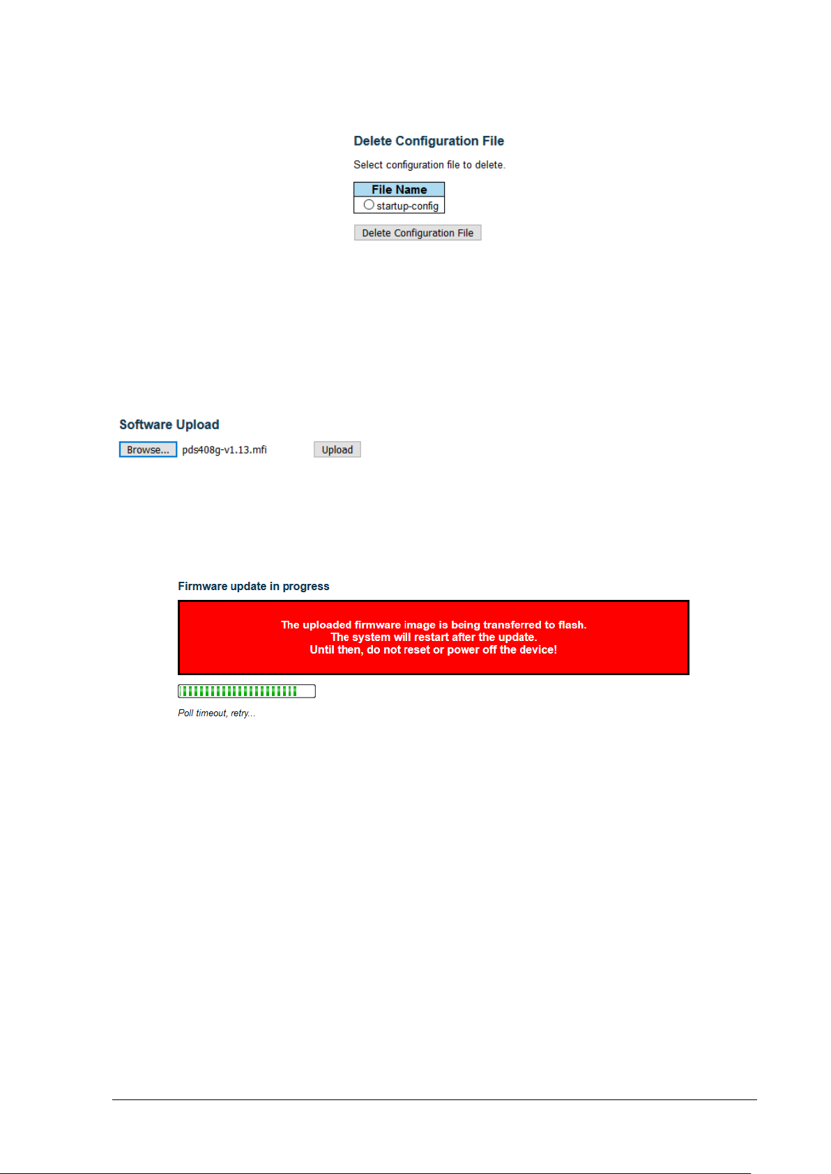
Maintenance Maintenance – Software Update
17.2.4 Delete Unit Configuration
Figure 18-5: Maintenance – Delete configuration
It is possible to delete any of the writable files stored in flash, including startup-config. If this is done and
the switch is rebooted without a prior Save operatio n, this effectively resets the switch to default
configuration.
17.3 Maintenance – Software Update
17.3.1 Upload New Version
Figure 18-6: Software Update – Upload new version
This Page allows the user to update the software used to run the Switch. Switch software use the mfi
extension. For example, my-switch-software.mfi. After the software image i s uploaded, a message is
displayed that the firmware update is initiated. After about a minute or so, the software is updated and
the switch restarts.
Figure 17-4: Software Update – in progress indication
Microsemi PDS-408G Web Management User Guide Ver. 1.0.1, 03-2019 92
Page 93

Maintenance Maintenance – Software Update
NOTES:
does not constitute an error.
17.3.2 Select active image
This page allows you to revert to the previous (alternate) image before the latest software update.
Pressing on the Activate Alternate Image will issue a warning message with an option to cancel the
reverting process. If you opt to continue the reverting process, the image bellow will be displayed during
the software reverting process.
Figure 17-5: Selecting active software image
Figure 17-6: Switching active image
1 - If the active firmware image is the alternate image, only the "Active Image" table is shown. In
this case, the Activate Alternate Image button is also disabled.
2 - If the alternate image is active (due to a corruption of the primary image or by manual
intervention), uploading a new firmware image to the device will automatically use the primary
image slot and activate this.
3 - The firmware version and date information may be empty for older fir mware releases. This
Microsemi PDS-408G Web Management User Guide Ver. 1.0.1, 03-2019 93
Page 94

Maintenance Maintenance – Software Update
17.3.3 Recovering from endless unit reboot after software update
In case of a rare failure, in which the unit enters endle ss software reboot cycles after software update
preventing access to the web interface, it is still possible to revert to the previous version before
performing software update by executing the f ol l owing steps:
1. Connect to the unit USB interface with a USBSerial Virtual COMM int erf ace with baud rate of
115200.
2. Upon Switch reboot, press CTRL+C, to stop the boot from launching the Switch software.
A RedBoot> prompt should appear.
3. Type fis swap linux linux.bk to revert the Switch to the older soft ware version.
4. Type reset to restart the Switch using the reverted software version.
Figure 17-7: Recovering from endless reboot after software update
Microsemi PDS-408G Web Management User Guide Ver. 1.0.1, 03-2019 94
Page 95

Diagnostics Diagnostics - View log file
18 DIAGNOSTICS
18.1 Diagnostics - View log file
Figure 18-1: View SysLog file
Each page shows up to 999 table entries, selected through the "entries per page" input field. Pressing
on one of the numbers under the ID column will show the specific SysLog message in greater detail.
Figure 18-2: Detailed single SysLog message
• Level –Select which specific SysLog message severity level to display. Possible SysLog
message levels are:
o Informational – lowest priority SysLog message level.
o Notice – higher than Informational.
o Warning – higher than Notice.
o Error – higher than Warning.
o All – shows SysLog messages from all levels.
• Clear Level – clear all SysLog messages from a spe cif i c S ysLog level, or from all levels.
You need to press the button for clear to be executed.
• Start from ID – the input field allows you to change the starting po i nt in the SysLog table
report. Clicking the button will upd ate the displayed table starting from that or the
closest next entry match.
Microsemi PDS-408G Web Management User Guide Ver. 1.0.1, 03-2019 95
Page 96

Diagnostics Diagnostics - Ping
NOTE:
• ID - The identification of the system log entry.
• Level - The level of the system log entry.
• Time - The occurred time of the system log entry.
• Message - The detail message of the system log entry.
SysLog messages are kept in the RAM File System, meaning that SysLog messages will be lost
whenever the Switch power is down, or t he Switch restart command is initiated.
18.2 Diagnostics - Ping
This page allows you to issue ICMP (IPv4, ICMPv6) PING packets to troubleshoot IP connectivity
issues.
It should be used to test network connectivity bet ween the unit and a remote network device.
Figure 18-3: Ping Web interface
• Hostname or IPv4/IPv6 Address - The address of the destination host such as 192.16 8.0. 50
for IPv4 or 2345::15 for IPv6, or Hostname such as my-computer.com.
• Payload Size - Sets the size of the ICMPv4/v6 data payload in bytes (excluding the size of
Ethernet, IP and ICMP headers). The default v al ue i s 56 by tes. The valid range is 2-1452
bytes.
• Packet Count - Determines the number of PING requests sent. The default value is 5. The
valid range is 1-60.
Pressing the Start button will initiate a series of pings as shown in the figure bellow.
Figure 18-4: Ping in action
Microsemi PDS-408G Web Management User Guide Ver. 1.0.1, 03-2019 96
Page 97

Diagnostics Diagnostics - RJ45 Cable test
NOTE:
test is complete
18.3 Diagnostics - RJ45 Cable test
This page is used for running the VeriPHY RJ45 Cable Diagnostics test for 10/100 and 1G copper
ports.
Pressing Start will start the diagnostics. This will take approximately 15 seconds for a single port. If all
ports are selected, this can take approximately 30 seconds. When completed, the page refreshes
automatically, and you can view the cable diagnostics results in the cable status table.
Figure 18-5: RJ45 cables test
VeriPHY RJ45 cable test is only accurate for cables in the length range of 7 - 140 meters. 10 and
100 Mbps ports will be linked down while running VeriPHY. Therefore, running VeriPHY on a 10
or 100 Mbps management port will cause the switch to stop responding until the VeriPHY RJ45
• Port - The port where you are requesting VeriPHY C abl e Diagnostics.
• Cable Status – Cable status for each of the four pairs inside the Ethernet cable
o Port: Port number.
o Pair: The status of the cable pair:
OK - Correctly terminated pair
Open - Open pair
Short - Shorted pair
Short A - Cross-pair short to pair A
Short B - Cross-pair short to pair B
Short C - Cross-pair short to pair C
Short D - Cross-pair short to pair D
Cross A - Abnormal cross-pair coupling with pair A
Cross B - Abnormal cross-pair coupling with pair B
Cross C - Abnormal cross-pair coupling with pair C
Cross D - Abnormal cross-pair coupling with pair D
Length: The length (in meters) of the cable pair. The resolution is 3 met ers
Microsemi PDS-408G Web Management User Guide Ver. 1.0.1, 03-2019 97
Page 98

Diagnostics Diagnostics – View CPU Load
18.4 Diagnostics – View CPU Load
This page shows the Switch CPU load.
Figure 18-6: Switch CPU load
Microsemi PDS-408G Web Management User Guide Ver. 1.0.1, 03-2019 98
Page 99

Save running config Diagnostics – View CPU Load
Revision Level / Date
Para. Affected
Description
1.0.1 19-3-19
Whole Document
initial document
NOTE:
19 SAVE RUNNING CONFIG
Pressing on save running config saves the switch’s running-config configuration to the Switch’s startupconfig configuration, so that next time the Switch is powered off and on or software rebooted, it will use
the same configuration as before it had been restarted.
All switch runtime configuration changes will be lost upon switch reboot, unless Save-RunningConfig was pressed, or CLI command copy running-config startu p-config was entered.
Revision History
For support contact: PoEsupport@microsemi.com
Visit our web site at: PoE Midspans, PoE Injectors & PoE Switches
Document PN: PD_PDS-408G_NMS_UG
Microsemi PDS-408G Web Management User Guide Ver. 1.0.1, 03-2019 99
 Loading...