

Page 1

UG0446
User Guide
SmartFusion2 and IGLOO2 FPGA High Speed DDR
Interfaces
Page 2

Microsemi Headquarters
One Enterprise, Aliso Viejo,
CA 92656 USA
Within the USA: +1 (800) 713-4113
Outside the USA: +1 (949) 380-6100
Sales: +1 (949) 380-6136
Fax: +1 (949) 215-4996
Email: sales.support@microsemi.com
www.microsemi.com
©2019 Microsemi, a wholly owned
subsidiary of Microchip Technology Inc. All
rights reserved. Microsemi and the
Microsemi logo are registered trademarks of
Microsemi Corporation. All other trademarks
and service marks are the property of their
respective owners.
Microsemi makes no warranty, representation, or guarantee regarding the information contained herein or the suitability of
its products and services for any particular purpose, nor does Microsemi assume any liability whatsoever arising out of the
application or use of any product or circuit. The products sold hereunder and any other products sold by Microsemi have
been subject to limited testing and should not be used in conjunction with mission-critical equipment or applications. Any
performance specifications are believed to be reliable but are not verified, and Buyer must conduct and complete all
performance and other testing of the products, alone and together with, or installed in, any end-products. Buyer shall not
rely on any data and performance specifications or parameters provided by Microsemi. It is the Buyer’s responsibility to
independently determine suitability of any products and to test and verify the same. The information provided by Microsemi
hereunder is provided “as is, where is” and with all faults, and the entire risk associated with such information is entirely
with the Buyer. Microsemi does not grant, explicitly or implicitly, to any party any patent rights, licenses, or any other IP
rights, whether with regard to such information itself or anything described by such information. Information provided in this
document is proprietary to Microsemi, and Microsemi reserves the right to make any changes to the information in this
document or to any products and services at any time without notice.
About Microsemi
Microsemi, a wholly owned subsidiary of Microchip Technology Inc. (Nasdaq: MCHP), offers a comprehensive portfolio of
semiconductor and system solutions for aerospace & defense, communications, data center and industrial markets.
Products include high-performance and radiation-hardened analog mixed-signal integrated circuits, FPGAs, SoCs and
ASICs; power management products; timing and synchronization devices and precise time solutions, setting the world's
standard for time; voice processing devices; RF solutions; discrete components; enterprise storage and communication
solutions, security technologies and scalable anti-tamper products; Ethernet solutions; Power-over-Ethernet ICs and
midspans; as well as custom design capabilities and services. Learn more at www.microsemi.com.
50200446. 7.0 6/19
Page 3

Contents
1 Revision History . . . . . . . . . . . . . . . . . . . . . . . . . . . . . . . . . . . . . . . . . . . . . . . . . . . . . 1
1.1 Revision 7.0 . . . . . . . . . . . . . . . . . . . . . . . . . . . . . . . . . . . . . . . . . . . . . . . . . . . . . . . . . . . . . . . . . . . . . . . 1
1.2 Revision 6.0 . . . . . . . . . . . . . . . . . . . . . . . . . . . . . . . . . . . . . . . . . . . . . . . . . . . . . . . . . . . . . . . . . . . . . . . 1
1.3 Revision 5.0 . . . . . . . . . . . . . . . . . . . . . . . . . . . . . . . . . . . . . . . . . . . . . . . . . . . . . . . . . . . . . . . . . . . . . . . 1
1.4 Revision 4.0 . . . . . . . . . . . . . . . . . . . . . . . . . . . . . . . . . . . . . . . . . . . . . . . . . . . . . . . . . . . . . . . . . . . . . . . 1
1.5 Revision 3.0 . . . . . . . . . . . . . . . . . . . . . . . . . . . . . . . . . . . . . . . . . . . . . . . . . . . . . . . . . . . . . . . . . . . . . . . 1
1.6 Revision 2.0 . . . . . . . . . . . . . . . . . . . . . . . . . . . . . . . . . . . . . . . . . . . . . . . . . . . . . . . . . . . . . . . . . . . . . . . 1
1.7 Revision 1.0 . . . . . . . . . . . . . . . . . . . . . . . . . . . . . . . . . . . . . . . . . . . . . . . . . . . . . . . . . . . . . . . . . . . . . . . 2
1.8 Revision 0.0 . . . . . . . . . . . . . . . . . . . . . . . . . . . . . . . . . . . . . . . . . . . . . . . . . . . . . . . . . . . . . . . . . . . . . . . 2
2 Overview . . . . . . . . . . . . . . . . . . . . . . . . . . . . . . . . . . . . . . . . . . . . . . . . . . . . . . . . . . 3
2.1 Contents . . . . . . . . . . . . . . . . . . . . . . . . . . . . . . . . . . . . . . . . . . . . . . . . . . . . . . . . . . . . . . . . . . . . . . . . . . 3
2.2 Additional Documentation . . . . . . . . . . . . . . . . . . . . . . . . . . . . . . . . . . . . . . . . . . . . . . . . . . . . . . . . . . . . 3
3 MDDR Subsystem . . . . . . . . . . . . . . . . . . . . . . . . . . . . . . . . . . . . . . . . . . . . . . . . . . . 5
3.1 Features . . . . . . . . . . . . . . . . . . . . . . . . . . . . . . . . . . . . . . . . . . . . . . . . . . . . . . . . . . . . . . . . . . . . . . . . . . 5
3.2 Memory Configurations . . . . . . . . . . . . . . . . . . . . . . . . . . . . . . . . . . . . . . . . . . . . . . . . . . . . . . . . . . . . . . 6
3.3 Performance . . . . . . . . . . . . . . . . . . . . . . . . . . . . . . . . . . . . . . . . . . . . . . . . . . . . . . . . . . . . . . . . . . . . . . 7
3.4 I/O Utilization . . . . . . . . . . . . . . . . . . . . . . . . . . . . . . . . . . . . . . . . . . . . . . . . . . . . . . . . . . . . . . . . . . . . . . 7
3.5 Functional Description . . . . . . . . . . . . . . . . . . . . . . . . . . . . . . . . . . . . . . . . . . . . . . . . . . . . . . . . . . . . . . . 8
3.5.1 Architecture Overview . . . . . . . . . . . . . . . . . . . . . . . . . . . . . . . . . . . . . . . . . . . . . . . . . . . . . . . . 8
3.5.2 Port List . . . . . . . . . . . . . . . . . . . . . . . . . . . . . . . . . . . . . . . . . . . . . . . . . . . . . . . . . . . . . . . . . . . 9
3.5.3 Initialization . . . . . . . . . . . . . . . . . . . . . . . . . . . . . . . . . . . . . . . . . . . . . . . . . . . . . . . . . . . . . . . 16
3.5.4 Details of Operation . . . . . . . . . . . . . . . . . . . . . . . . . . . . . . . . . . . . . . . . . . . . . . . . . . . . . . . . . 18
3.5.5 MDDR Subsystem Features Configuration . . . . . . . . . . . . . . . . . . . . . . . . . . . . . . . . . . . . . . . 25
3.6 How to Use MDDR in IGLOO2 Device . . . . . . . . . . . . . . . . . . . . . . . . . . . . . . . . . . . . . . . . . . . . . . . . . . 32
3.6.1 Configuring MDDR . . . . . . . . . . . . . . . . . . . . . . . . . . . . . . . . . . . . . . . . . . . . . . . . . . . . . . . . . 33
3.6.2 Accessing MDDR from FPGA Fabric through the AXI Interface . . . . . . . . . . . . . . . . . . . . . . . 43
3.6.3 Accessing MDDR from FPGA Fabric Through the AHB Interface . . . . . . . . . . . . . . . . . . . . . . 48
3.6.4 Accessing MDDR from the HPDMA . . . . . . . . . . . . . . . . . . . . . . . . . . . . . . . . . . . . . . . . . . . . 50
3.7 Timing Diagrams . . . . . . . . . . . . . . . . . . . . . . . . . . . . . . . . . . . . . . . . . . . . . . . . . . . . . . . . . . . . . . . . . . 52
3.8 Timing Optimization Technique for AXI . . . . . . . . . . . . . . . . . . . . . . . . . . . . . . . . . . . . . . . . . . . . . . . . . 55
3.9 DDR Memory Device Examples . . . . . . . . . . . . . . . . . . . . . . . . . . . . . . . . . . . . . . . . . . . . . . . . . . . . . . . 58
3.9.1 Example 1: Connecting 32-Bit DDR2 to MDDR_PADs . . . . . . . . . . . . . . . . . . . . . . . . . . . . . . 58
3.9.2 Example 2: Connecting 32-Bit DDR3 to MDDR_PADs with SECDED . . . . . . . . . . . . . . . . . . 59
3.9.3 Example 3: Connecting 16-Bit LPDDR to MDDR_PADs with SECDED . . . . . . . . . . . . . . . . . 60
3.10 Board Design Considerations . . . . . . . . . . . . . . . . . . . . . . . . . . . . . . . . . . . . . . . . . . . . . . . . . . . . . . . . 61
3.11 MDDR Configuration Registers . . . . . . . . . . . . . . . . . . . . . . . . . . . . . . . . . . . . . . . . . . . . . . . . . . . . . . . 61
3.11.1 SYSREG Configuration Register Summary . . . . . . . . . . . . . . . . . . . . . . . . . . . . . . . . . . . . . . 62
3.11.2 DDR Controller Configuration Register Summary . . . . . . . . . . . . . . . . . . . . . . . . . . . . . . . . . . 63
3.11.3 DDR Controller Configuration Register Bit Definitions . . . . . . . . . . . . . . . . . . . . . . . . . . . . . . . 67
3.11.4 PHY Configuration Register Summary . . . . . . . . . . . . . . . . . . . . . . . . . . . . . . . . . . . . . . . . . 103
3.11.5 PHY Configuration Register Bit Definitions . . . . . . . . . . . . . . . . . . . . . . . . . . . . . . . . . . . . . . 103
3.11.6 DDR_FIC Configuration Registers Summary . . . . . . . .
3.11.7 DDR_FIC Configuration Register Bit Definitions . . . . . . . . . . . . . . . . . . . . . . . . . . . . . . . . . . 105
3.12 Appendix A: How to Use the MDDR in SmartFusion2 . . . . . . . . . . . . . . . . . . . . . . . . . . . . . . . . . . . . . 112
3.12.1 Design Flow Using System Builder . . . . . . . . . . . . . . . . . . . . . . . . . . . . . . . . . . . . . . . . . . . . 112
3.12.2 Design Flow Using SmartDesign . . . . . . . . . . . . . . . . . . . . . . . . . . . . . . . . . . . . . . . . . . . . . . 121
3.12.3 Use Model 1: Accessing MDDR from FPGA Fabric Through the AXI Interface . . . . . . . . . . 126
. . . . . . . . . . . . . . . . . . . . . . . . . . . . 103
Microsemi Proprietary UG0446 User Guide Revision 7.0 iii
Page 4

3.12.4 Use Model 2: Accessing MDDR from FPGA Fabric Through the AHB Interface . . . . . . . . . . 128
3.12.5 Use Model 3: Accessing MDDR from Cortex-M3 Processor . . . . . . . . . . . . . . . . . . . . . . . . . 130
3.12.6 Use Model 4: Accessing MDDR from the HPDMA . . . . . . . . . . . . . . . . . . . . . . . . . . . . . . . . 132
4 Fabric DDR Subsystem . . . . . . . . . . . . . . . . . . . . . . . . . . . . . . . . . . . . . . . . . . . . . 134
4.1 Features . . . . . . . . . . . . . . . . . . . . . . . . . . . . . . . . . . . . . . . . . . . . . . . . . . . . . . . . . . . . . . . . . . . . . . . . 134
4.2 Memory Configurations . . . . . . . . . . . . . . . . . . . . . . . . . . . . . . . . . . . . . . . . . . . . . . . . . . . . . . . . . . . . 135
4.3 Performance . . . . . . . . . . . . . . . . . . . . . . . . . . . . . . . . . . . . . . . . . . . . . . . . . . . . . . . . . . . . . . . . . . . . 135
4.4 I/O Utilization . . . . . . . . . . . . . . . . . . . . . . . . . . . . . . . . . . . . . . . . . . . . . . . . . . . . . . . . . . . . . . . . . . . . 136
4.5 Functional Description . . . . . . . . . . . . . . . . . . . . . . . . . . . . . . . . . . . . . . . . . . . . . . . . . . . . . . . . . . . . . 136
4.5.1 Architecture Overview . . . . . . . . . . . . . . . . . . . . . . . . . . . . . . . . . . . . . . . . . . . . . . . . . . . . . . 136
4.5.2 Port List . . . . . . . . . . . . . . . . . . . . . . . . . . . . . . . . . . . . . . . . . . . . . . . . . . . . . . . . . . . . . . . . . 138
4.6 Initialization . . . . . . . . . . . . . . . . . . . . . . . . . . . . . . . . . . . . . . . . . . . . . . . . . . . . . . . . . . . . . . . . . . . . . 144
4.6.1 Reset Sequence . . . . . . . . . . . . . . . . . . . . . . . . . . . . . . . . . . . . . . . . . . . . . . . . . . . . . . . . . . 144
4.6.2 ZQ Calibration . . . . . . . . . . . . . . . . . . . . . . . . . . . . . . . . . . . . . . . . . . . . . . . . . . . . . . . . . . . . 145
4.6.3 Details of Operation . . . . . . . . . . . . . . . . . . . . . . . . . . . . . . . . . . . . . . . . . . . . . . . . . . . . . . . . 146
4.6.4 FDDR Subsystem Features Configuration . . . . . . . . . . . . . . . . . . . . . . . . . . . . . . . . . . . . . . 152
4.6.5 Memory Type . . . . . . . . . . . . . . . . . . . . . . . . . . . . . . . . . . . . . . . . . . . . . . . . . . . . . . . . . . . . . 152
4.6.6 Bus Width Configurations . . . . . . . . . . . . . . . . . . . . . . . . . . . . . . . . . . . . . . . . . . . . . . . . . . . 152
4.6.7 Burst Mode . . . . . . . . . . . . . . . . . . . . . . . . . . . . . . . . . . . . . . . . . . . . . . . . . . . . . . . . . . . . . . 153
4.6.8 Configuring Dynamic DRAM Constraints . . . . . . . . . . . . . . . . . . . . . . . . . . . . . . . . . . . . . . . 153
4.6.9 Dynamic DRAM Bank Constraints . . . . . . . . . . . . . . . . . . . . . . . . . . . . . . . . . . . . . . . . . . . . . 153
4.6.10 Address Mapping . . . . . . . . . . . . . . . . . . . . . . . . . . . . . . . . . . . . . . . . . . . . . . . . . . . . . . . . . . 155
4.7 How to Use FDDR in IGLOO2 Devices . . . . . . . . . . . . . . . . . . . . . . . . . . . . . . . . . . . . . . . . . . . . . . . . 158
4.7.1 Configuring FDDR . . . . . . . . . . . . . . . . . . . . . . . . . . . . . . . . . . . . . . . . . . . . . . . . . . . . . . . . . 158
4.7.2 Accessing FDDR from FPGA Fabric through the AXI Interface . . . . . . . . . . . . . . . . . . . . . . 166
4.7.3 Accessing FDDR from FPGA Fabric through the AHB Interface . . . . . . . . . . . . . . . . . . . . . . 171
4.8 DDR Memory Device Examples . . . . . . . . . . . . . . . . . . . . . . . . . . . . . . . . . . . . . . . . . . . . . . . . . . . . . . 173
4.8.1 Example 1: Connecting 32-Bit DDR2 to FDDR_PADs . . . . . . . . . . . . . . . . . . . . . . . . . . . . . 173
4.8.2 Example 2: Connecting 32-Bit DDR3 to FDDR_PADs with SECDED . . . . . . . . . . . . . . . . . . 173
4.8.3 Example 3: Connecting 16-Bit LPDDR to FDDR_PADs with SECDED . . . . . . . . . . . . . . . . 174
4.9 FDDR Configuration Registers . . . . . . . . . . . . . . . . . . . . . . . . . . . . . . . . . . . . . . . . . . . . . . . . . . . . . . 175
4.9.1 FDDR SYSREG Configuration Register Summary . . . . . . . . . . . . . . . . . . . . . . . . . . . . . . . . 176
4.9.2 FDDR SYSREG Configuration Register Bit Definitions . . . . . . . . . . . . . . . . . . . . . . . . . . . . . 176
4.10 Appendix A: How to Use the FDDR in SmartFusion2 Devices . . . . . . . . . . . . . . . . . . . . . . . . . . . . . . 184
4.10.1 Design Flow Using System Builder . . . . . . . . . . . . . . . . . . . . . . . . . . . . . . . . . . . . . . . . . . . . 184
4.10.2 Design Flow Using SmartDesign . . . . . . . . . . . . . . . . . . . . . . . . . . . . . . . . . . . . . . . . . . . . . . 192
4.10.3 Use Model 1: Accessing FDDR from FPGA Fabric Through AXI Interface . . . . . . . . . . . . . . 196
4.10.4 Use Model 2: Accessing FDDR from FPGA Fabric Through AHB Interface . . . . . . . . . . . . . 199
4.11 Appendix B: Register Lock Bits Configuration . . . . . . . . . . . . . . . . . . . . . . . . . . . . . . . . . . . . . . . . . . . 204
4.11.1 Lock Bit File . . . . . . . . . . . . . . . . . . . . . . . . . . . . . . . . . . . . . . . . . . . . . . . . . . . . . . . . . . . . . . 204
4.11.2 Lock Bit File Syntax . . . . . . . . . . . . . . . . . . . . . . . . . . . . . . . . . . . . . . . . . . . . . . . . . . . . . . . . 204
4.11.3 Locking and Unlocking a Register . . . . . . . . . . . . . . . . . . . . . . . . . . . . . . . . . . . . . . . . . . . . . 205
5 DDR Bridge . . . . . . . . . . . . . . . . . . . . . . . . . . . . . . . . . . . . . . . . . . . . . . . . . . . . . . 207
5.1 Functional Description . . . . . . . . . . . . . . . . . . . . . . . . . . . . . . . . . . . . . . . . . . . . . . . . . . . . . . . . . . . . . 208
5.1.1 Architecture Overview . . . . . . . . . . . . . . . . . . . . . . . . . . . . . . . . . . . . . . . . . . . . . . . . . . . . . . 208
5.1.2 Details of Operation . . . . . . . . . . . . . . . . . . . . . . . . . . . . . . . . . . . . . . . . . . . . . . . . . . . . . . . . 209
5.2 How to Use DDR Bridge in IGLOO2 Device . . . . . . . . . . . . . . . . . . . . . . . . . . . . . . . . . . . . . . . . . . . . 212
5.2.1 Configuring the DDR Bridge . . . . . . . . . . . . . . . . . . . . . . . . . . . . . . . . . . . . . . . . . . . . . . . . . 213
5.2.2 High-Speed Data Transactions from HPDMA . . . . . . . . . . . . . . . . . . . . . . . . . . . . . . . . . . . . 214
5.2.3 Selecting Non-Bufferable Region . . . . . . . . . . . . . . . . . . . . . . . . . . . . . . . . . . . . . . . . . . . . . 215
5.3 SYSREG Control Registers . . . . . . . . . . . . . . . . . . . . . . . . . . . . . . . . . . . . . . . . . . . . . . . . . . . . . . . . . 215
5.4 DDR Bridge Control Registers in MDDR and FDDR . . . . . . . . . . . . . . . . . . . . . . . . . . . . . . . . . . . . . . 216
5.5 Appendix A: How to Use DDR Bridge in SmartFusion2 Device . . . . . . . . . . . . . . . . . . . . . . . . . . . . . . 216
5.5.1 Use Model 1: High Speed Data Transactions from Cortex-M3 Processor . . . . . . . . . . . . . . 217
Microsemi Proprietary UG0446 User Guide Revision 7.0 iv
Page 5

5.5.2 Use Model 2: Selecting Non-Bufferable Region . . . . . . . . . . . . . . . . . . . . . . . . . . . . . . . . . . 218
6 Soft Memory Controller Fabric Interface Controller . . . . . . . . . . . . . . . . . . . . . . . . 219
6.1 Functional Description . . . . . . . . . . . . . . . . . . . . . . . . . . . . . . . . . . . . . . . . . . . . . . . . . . . . . . . . . . . . . 220
6.1.1 Port List . . . . . . . . . . . . . . . . . . . . . . . . . . . . . . . . . . . . . . . . . . . . . . . . . . . . . . . . . . . . . . . . . 220
6.2 How to Use SMC_FIC in IGLOO2 Device . . . . . . . . . . . . . . . . . . . . . . . . . . . . . . . . . . . . . . . . . . . . . . 225
6.3 SYSREG Control Register for SMC_FIC . . . . . . . . . . . . . . . . . . . . . . . . . . . . . . . . . . . . . . . . . . . . . . . 227
6.4 Appendix A: How to Use SMC_FIC in SmartFusion2 Devices . . . . . . . . . . . . . . . . . . . . . . . . . . . . . . 227
6.4.1 Design Flow . . . . . . . . . . . . . . . . . . . . . . . . . . . . . . . . . . . . . . . . . . . . . . . . . . . . . . . . . . . . . . 227
6.4.2 Use Model 1: Accessing SDRAM from MSS Through CoreSDR_AXI . . . . . . . . . . . . . . . . . . 228
Microsemi Proprietary UG0446 User Guide Revision 7.0 v
Page 6

Figures
Figure 1 System Level MDDR Block Diagram . . . . . . . . . . . . . . . . . . . . . . . . . . . . . . . . . . . . . . . . . . . . . . . . 6
Figure 2 MDDR Subsystem Functional Block Diagram . . . . . . . . . . . . . . . . . . . . . . . . . . . . . . . . . . . . . . . . . 8
Figure 3 Reset Sequence . . . . . . . . . . . . . . . . . . . . . . . . . . . . . . . . . . . . . . . . . . . . . . . . . . . . . . . . . . . . . . . 17
Figure 4 DDR_FIC Block Diagram . . . . . . . . . . . . . . . . . . . . . . . . . . . . . . . . . . . . . . . . . . . . . . . . . . . . . . . . 18
Figure 5 AXI Transaction Controller Block Diagram . . . . . . . . . . . . . . . . . . . . . . . . . . . . . . . . . . . . . . . . . . . 20
Figure 6 DDR Controller Block Diagram . . . . . . . . . . . . . . . . . . . . . . . . . . . . . . . . . . . . . . . . . . . . . . . . . . . . 21
Figure 7 DDR RMW Operation (32-Bit DDR Bus Width and Burst Length 8) . . . . . . . . . . . . . . . . . . . . . . . . 23
Figure 8 DDR RMW Operation (16-Bit DDR Bus Width and Burst Length 8) . . . . . . . . . . . . . . . . . . . . . . . . 23
Figure 9 DDR RMW Operation (8-Bit DDR Bus Width and Burst Length 8) . . . . . . . . . . . . . . . . . . . . . . . . . 23
Figure 10 Address Mapping . . . . . . . . . . . . . . . . . . . . . . . . . . . . . . . . . . . . . . . . . . . . . . . . . . . . . . . . . . . . . . 28
Figure 11 System Builder—Device Features Window . . . . . . . . . . . . . . . . . . . . . . . . . . . . . . . . . . . . . . . . . . 33
Figure 12 MDR Initialization Path . . . . . . . . . . . . . . . . . . . . . . . . . . . . . . . . . . . . . . . . . . . . . . . . . . . . . . . . . . 34
Figure 13 I/O Drive Strength Setting . . . . . . . . . . . . . . . . . . . . . . . . . . . . . . . . . . . . . . . . . . . . . . . . . . . . . . . . 36
Figure 14 Selecting I/O Standard as LVCMOS18 or LPDDRI . . . . . . . . . . . . . . . . . . . . . . . . . . . . . . . . . . . . 37
Figure 15 Memory Initialization Configuration . . . . . . . . . . . . . . . . . . . . . . . . . . . . . . . . . . . . . . . . . . . . . . . . . 39
Figure 16 Memory Timing Configuration . . . . . . . . . . . . . . . . . . . . . . . . . . . . . . . . . . . . . . . . . . . . . . . . . . . . . 40
Figure 17 System Builder - Peripherals Tab . . . . . . . . . . . . . . . . . . . . . . . . . . . . . . . . . . . . . . . . . . . . . . . . . . 41
Figure 18 MDDR_CLK Configuration . . . . . . . . . . . . . . . . . . . . . . . . . . . . . . . . . . . . . . . . . . . . . . . . . . . . . . . 42
Figure 19 DDR_FIC_CLK Configuration . . . . . . . . . . . . . . . . . . . . . . . . . . . . . . . . . . . . . . . . . . . . . . . . . . . . . 42
Figure 20 I/O Editor Window . . . . . . . . . . . . . . . . . . . . . . . . . . . . . . . . . . . . . . . . . . . . . . . . . . . . . . . . . . . . . . 43
Figure 21 MDDR with AXI Interfaces . . . . . . . . . . . . . . . . . . . . . . . . . . . . . . . . . . . . . . . . . . . . . . . . . . . . . . . 44
Figure 22 System Builder - Device Features Tab . . . . . . . . . . . . . . . . . . . . . . . . . . . . . . . . . . . . . . . . . . . . . . 45
Figure 23 Memory Configuration . . . . . . . . . . . . . . . . . . . . . . . . . . . . . . . . . . . . . . . . . . . . . . . . . . . . . . . . . . 45
Figure 24 Peripherals Tab with the Master Added and Configure Icon Highlighted . . . . . . . . . . . . . . . . . . . . 46
Figure 25 AMBA Master Configuration . . . . . . . . . . . . . . . . . . . . . . . . . . . . . . . . . . . . . . . . . . . . . .
Figure 26 System Clocks Configuration . . . . . . . . . . . . . . . . . . . . . . . . . . . . . . . . . . . . . . . . . . . . . . . . . . . . . 47
Figure 27 SmartDesign Connections (Top Level View) . . . . . . . . . . . . . . . . . . . . . . . . . . . . . . . . . . . . . . . . . 48
Figure 28 MDDR with Single AHB-Lite Interface . . . . . . . . . . . . . . . . . . . . . . . . . . . . . . . . . . . . . . . . . . . . . . 49
Figure 29 MDDR with HPDMA . . . . . . . . . . . . . . . . . . . . . . . . . . . . . . . . . . . . . . . . . . . . . . . . . . . . . . . . . . . . 50
Figure 30 System Builder - Device Features Tab . . . . . . . . . . . . . . . . . . . . . . . . . . . . . . . . . . . . . . . . . . . . . . 50
Figure 31 Memory Configurations . . . . . . . . . . . . . . . . . . . . . . . . . . . . . . . . . . . . . . . . . . . . . . . . . . . . . . . . . . 51
Figure 32 Clocks Configuration . . . . . . . . . . . . . . . . . . . . . . . . . . . . . . . . . . . . . . . . . . . . . . . . . . . . . . . . . . . . 51
Figure 33 AXI Single Write Transaction and Corresponding DDR Controller Commands . . . . . . . . . . . . . . . 52
Figure 34 DDR Controller Command Sequence for Single AXI Write Transaction . . . . . . . . . . . . . . . . . . . . . 52
Figure 35 AXI Single Read Transaction and Corresponding DDR Controller Commands . . . . . . . . . . . . . . . 53
Figure 36 AXI INCR16 Write Transaction and Corresponding DDR Controller Commands . . . . . . . . . . . . . . 53
Figure 37 AXI INCR16 Write Transaction . . . . . . . . . . . . . . . . . . . . . . . . . . . . . . . . . . . . . . . . . . . . . . . . . . . . 54
Figure 38 DDR Controller Command Sequence for AXI INCR16 Write Transaction . . . . . . . . . . . . . . . . . . . 54
Figure 39 AXI INCR-16 Read Transaction and Corresponding DDR Controller Commands . . . . . . . . . . . . . 54
Figure 40 DDR Controller Command Sequence for AXI INCR-16 Read Transaction . . . . . . . . . . . . . . . . . . 55
Figure 41 AXI Timing Optimization Logic . . . . . . . . . . . . . . . . . . . . . . . . . . . . . . . . . . . . . . . . . . . . . . . . . . . . 56
Figure 42 Timing Diagram . . . . . . . . . . . . . . . . . . . . . . . . . . . . . . . . . . . . . . . . . . . . . . . . . . . . . . . . . . . . . . . 56
Figure 43 x16 DDR2 SDRAM Connected to MDDR . . . . . . . . . . . . . . . . . . . . . . . . . . . . . . . . . . . . . . . . . . . . 59
Figure 44 ×8 DDR3 SDRAM Connection to MDDR . . . . . . . . . . . . . . . . . . . . . . . . . . . . . . . . . . . . . . . . . . . . 60
Figure 45 ×16 LPDDR1 SDRAM Connection to MDDR . . . . . . . . . . . . . . . . . . . . . . . . . . . . . . . . . . . . . . . . . 61
Figure 46 System Builder - Device Features Window . . . . . . . . . . . . . . . . . . . . . . . . . . . . . . . . . . . . . . . . . . 113
Figure 47 MSS External DDR Memory Selection . . . . . . . . . . . . . . . . . . . . . . . . . . . . . . . . . . . . . . . . . . . . . 113
Figure 48 I/O Drive Strength Setting . . . . . . . . . . . . . . . . . . . . . . . . . . . . . . . . . . . . . . . . . . . . . . . . . . . . . . . 114
Figure 49 Selecting I/O Standard as LVCMOS18 or LPDDRI . . . . . . . . . . . . . . . . . . . . . . . . . . . . . . . . . . . 115
Figure 50 DDR Memory initialization Settings . . . . . . . . . . . . . . . . . . . . . . . . . . . . . . . . . . . . . . . . .
Figure 51 DDR Memory Timing Settings . . . . . . . . . . . . . . . . . . . . . . . . . . . . . . . . . . . . . . . . . . . . . . . . . . . 118
Figure 52 MSS DDR FIC Subsystem Configuration . . . . . . . . . . . . . . . . . . . . . . . . . . . . . . . . . . . . . . . . . . . 119
Figure 53 MDDR Clock Configuration . . . . . . . . . . . . . . . . . . . . . . . . . . . . . . . . . . . . . . . . . . . . . . . . . . . . . . 120
Figure 54 DDR_FIC Clock Configuration . . . . . . . . . . . . . . . . . . . . . . . . . . . . . . . . . . . . . . . . . . . . . . . . . . . 121
. . . . . . . . 46
. . . . . . 117
Microsemi Proprietary UG0446 User Guide Revision 7.0 vi
Page 7

Figure 55 Design Flow . . . . . . . . . . . . . . . . . . . . . . . . . . . . . . . . . . . . . . . . . . . . . . . . . . . . . . . . . . . . . . . . . 122
Figure 56 MDDR Configurator . . . . . . . . . . . . . . . . . . . . . . . . . . . . . . . . . . . . . . . . . . . . . . . . . . . . . . . . . . . 122
Figure 57 Memory Interface Configuration . . . . . . . . . . . . . . . . . . . . . . . . . . . . . . . . . . . . . . . . . . . . . . . . . . 123
Figure 58 MSS External DDR Memory Configurator . . . . . . . . . . . . . . . . . . . . . . . . . . . . . . . . . . . . . . . . . . 123
Figure 59 MDDR Clock Configuration . . . . . . . . . . . . . . . . . . . . . . . . . . . . . . . . . . . . . . . . . . . . . . . . . . . . . . 124
Figure 60 MDDR Clock Configuration . . . . . . . . . . . . . . . . . . . . . . . . . . . . . . . . . . . . . . . . . . . . . . . . . . . . . . 124
Figure 61 FIC_2 Configuration . . . . . . . . . . . . . . . . . . . . . . . . . . . . . . . . . . . . . . . . . . . . . . . . . . . . . . . . . . . 125
Figure 62 I/O Configuration . . . . . . . . . . . . . . . . . . . . . . . . . . . . . . . . . . . . . . . . . . . . . . . . . . . . . . . . . . . . . . 125
Figure 63 MDDR with AXI Interface . . . . . . . . . . . . . . . . . . . . . . . . . . . . . . . . . . . . . . . . . . . . . . . . . . . . . . . 126
Figure 64 MSS External Memory Configuration . . . . . . . . . . . . . . . . . . . . . . . . . . . . . . . . . . . . . . . . . . . . . . 127
Figure 65 Configuring FIC_2 . . . . . . . . . . . . . . . . . . . . . . . . . . . . . . . . . . . . . . . . . . . . . . . . . . . . . . . . . . . . . 127
Figure 66 MDDR Clock Configuration . . . . . . . . . . . . . . . . . . . . . . . . . . . . . . . . . . . . . . . . . . . . . . . . . . . . . . 127
Figure 67 SmartDesign Canvas . . . . . . . . . . . . . . . . . . . . . . . . . . . . . . . . . . . . . . . . . . . . . . . . . . . . . . . . . . 128
Figure 68 MDDR with Single AHB Interface . . . . . . . . . . . . . . . . . . . . . . . . . . . . . . . . . . . . . . . . . . . . . . . . . 129
Figure 69 MDDR with Dual AHB Interface . . . . . . . . . . . . . . . . . . . . . . . . . . . . . . . . . . . . . . . . . . . . . . . . . . 130
Figure 70 Accessing MDDR from Cortex-M3 Processor . . . . . . . . . . . . . . . . . . . . . . . . . . . . . . . . . . . . . . . . 131
Figure 71 MSS External Memory Configuration . . . . . . . . . . . . . . . . . . . . . . . . . . . . . . . . . . . . . . . . . . . . . . 131
Figure 72 Configuring MDDR_CLK . . . . . . . . . . . . . . . . . . . . . . . . . . . . . . . . . . . . . . . . . . . . . . . . . . . . . . . . 132
Figure 73 Accessing MDDR from HPDMA . . . . . . . . . . . . . . . . . . . . . . . . . . . . . . . . . . . . . . . . . . . . . . . . . . 133
Figure 74 System Level FDDR Block Diagram . . . . . . . . . . . . . . . . . . . . . . . . . . . . . . . . . . . . . . . . . . . . . . . 134
Figure 75 FDDR Subsystem Functional Block Diagram . . . . . . . . . . . . . . . . . . . . . . . . . . . . . . . . . . . . . . . . 136
Figure 76 Reset Sequence . . . . . . . . . . . . . . . . . . . . . . . . . . . . . . . . . . . . . . . . . . . . . . . . . . . . . . . . . . . . . . 145
Figure 77 DDR_FIC Block Diagram . . . . . . . . . . . . . . . . . . . . . . . . . . . . . . . . . . . . . . . . . . . . . . . . . . . . . . . 148
Figure 78 AXI Transaction Controller Block Diagram . . . . . . .
Figure 79 DDR Controller Block Diagram . . . . . . . . . . . . . . . . . . . . . . . . . . . . . . . . . . . . . . . . . . . . . . . . . . . 150
Figure 80 Address Mapping . . . . . . . . . . . . . . . . . . . . . . . . . . . . . . . . . . . . . . . . . . . . . . . . . . . . . . . . . . . . . 155
Figure 81 System Builder - Device Features Window . . . . . . . . . . . . . . . . . . . . . . . . . . . . . . . . . . . . . . . . . . 158
Figure 82 System Builder - Device Features Tab . . . . . . . . . . . . . . . . . . . . . . . . . . . . . . . . . . . . . . . . . . . . . 159
Figure 83 Fabric DDR Memory Configuration . . . . . . . . . . . . . . . . . . . . . . . . . . . . . . . . . . . . . . . . . . . . . . . . 160
Figure 84 Selecting I/O Standard as LVCMOS18 or LPDDRI . . . . . . . . . . . . . . . . . . . . . . . . . . . . . . . . . . . 161
Figure 85 Memory Initialization Configuration . . . . . . . . . . . . . . . . . . . . . . . . . . . . . . . . . . . . . . . . . . . . . . . . 163
Figure 86 Memory Timing Configuration . . . . . . . . . . . . . . . . . . . . . . . . . . . . . . . . . . . . . . . . . . . . . . . . . . . . 164
Figure 87 System Builder - Peripherals Tab . . . . . . . . . . . . . . . . . . . . . . . . . . . . . . . . . . . . . . . . . . . . . . . . . 165
Figure 88 FDDR Clock Configuration . . . . . . . . . . . . . . . . . . . . . . . . . . . . . . . . . . . . . . . . . . . . . . . . . . . . . . 166
Figure 89 I/O Editor Window . . . . . . . . . . . . . . . . . . . . . . . . . . . . . . . . . . . . . . . . . . . . . . . . . . . . . . . . . . . . . 166
Figure 90 FDDR Subsystem with AXI Interface . . . . . . . . . . . . . . . . . . . . . . . . . . . . . . . . . . . . . . . . . . . . . . 167
Figure 91 System Builder - Device Features Tab . . . . . . . . . . . . . . . . . . . . . . . . . . . . . . . . . . . . . . . . . . . . . 168
Figure 92 Memory Configuration . . . . . . . . . . . . . . . . . . . . . . . . . . . . . . . . . . . . . . . . . . . . . . . . . . . . . . . . . 168
Figure 93 Fabric DDR Subsystem Configuration Dialog . . . . . . . . . . . . . . . . . . . . . . . . . . . . . . . . . . . . . . . . 169
Figure 94 AMBA Master Configuration . . . . . . . . . . . . . . . . . . . . . . . . . . . . . . . . . . . . . . . . . . . . . . . . . . . . . 169
Figure 95 Clocks Configuration . . . . . . . . . . . . . . . . . . . . . . . . . . . . . . . . . . . . . . . . . . . . . . . . . . . . . . . . . . . 170
Figure 96 SmartDesign Connections (Top Level View) . . . . . . . . . . . . . . . . . . . . . . . . . . . . . . . . . . . . . . . . 171
Figure 97 FDDR with AHB-Lite interface . . . . . . . . . . . . . . . . . . . . . . . . . . . . . . . . . . . . . . . . . . . . . . . . . . . 172
Figure 98 x16 DDR2 SDRAM Connected to FDDR . . . . . . . . . . . . . . . . . . . . . . . . . . . . . . . . . . . . . . . . . . . 173
Figure 99 x8 DDR3 SDRAM Connection to FDDR . . . . . . . . . . . . . . . . . . . . . . . . . . . . . . . . . . . . . . . . . . . . 174
Figure 100 x16 LPDDR1 SDRAM Connection to FDDR . . . . . . . . . . . . . . . . . . . . . . . . . . . . . . . . . . . . . . . . . 175
Figure 101 System Builder - Device Features Window . . . . . . . . . . . . . . . . . . . . . . . . . . . . . . . . . . . . . . . . . . 185
Figure 102 MSS External DDR Memory Selection . . . . . . . . . . . . . . . . . . . . . . . . . . . . . . . . . . . . . . . . . . . . . 186
Figure 103 Fabric DDR Memory Settings . . . . . . . . . . . . . . . . . . . . . . . . . . . . . . . . . . . . . . . . . . . . . . . . . . . . 187
Figure 104 Selecting I/O Standard as LVCMOS18 or LPDDRI . . . . . . . . . . . . . . . . . . . . . . . . . . . . . . . . . . . 187
Figure 105 DDR Memory initialization Settings . . . . . . . . . . . . . . . . . . . . . . . . . . . . . . . . . . . . . . . . . . . . . . . 189
Figure 106 DDR Memory Timing Settings . . . . . . . . . . . . . . . . . . . . . . . . . . . . . . . . . . . . . . . . . . . . . . . . . . . 190
Figure 107 MSS DDR FIC Subsystem Configuration . . . . . . . . . . . . . . . . . . . . . . . . . . . . . . . . . . . . . . . . . . . 191
Figure 108 FDDR Clock Configuration . . . . . . . . . . . . . . . . . . . . . . . . . . . . . . . . . . . . . . . . . . . . . . . . . . . . . . 192
Figure 109 Design Flow . . . . . . . . . . . . . . . . . . . . . . . . . . . . . . . . . . . . . . . . . . . . . . . . . . . . . . . . . . . . . . . . . 193
Figure 110 Fabric External Memory DDR Controller Configurator . . . . . . . . . . . . . . . . . . . . . . . . . . . . . . . . . 194
Figure 111 FIC Configuration . . . . . . . . . . . . . . . . . . . . . . . . . . . . . . . . . . . . . . . . . . . . . . . . . . . . . . . . . . . . . 195
Figure 112 I/O Configuration . . . . . . . . . . . . . . . . . . . . . . . . . . . . . . . . . . . . . . . . . . . . . . . . . . . . . . . . . . . . . . 195
Figure 113 FDDR with AXI Interface . . . . . . . . . . . . . . . . . . . . . . . . . . . . . . . . . . . . . . . . . . . . . . . . . . . . . . . . 196
. . . . . . . . . . . . . . . . . . . . . . . . . . . . . . . . . . . 149
Microsemi Proprietary UG0446 User Guide Revision 7.0 vii
Page 8

Figure 114 FDDR Configuration . . . . . . . . . . . . . . . . . . . . . . . . . . . . . . . . . . . . . . . . . . . . . . . . . . . . . . . . . . . 197
Figure 115 Fabric CCC Configuration . . . . . . . . . . . . . . . . . . . . . . . . . . . . . . . . . . . . . . . . . . . . . . . . . . . . . . . 198
Figure 116 SmartDesign Canvas . . . . . . . . . . . . . . . . . . . . . . . . . . . . . . . . . . . . . . . . . . . . . . . . . . . . . . . . . . 198
Figure 117 Accessing FDDR Subsystem Through Dual AHB Interface . . . . . . . . . . . . . . . . . . . . . . . . . . . . . 199
Figure 118 FIC_2 Configuration . . . . . . . . . . . . . . . . . . . . . . . . . . . . . . . . . . . . . . . . . . . . . . . . . . . . . . . . . . . 200
Figure 119 MSS CCC Configuration . . . . . . . . . . . . . . . . . . . . . . . . . . . . . . . . . . . . . . . . . . . . . . . . . . . . . . . . 200
Figure 120 FDDR Configuration . . . . . . . . . . . . . . . . . . . . . . . . . . . . . . . . . . . . . . . . . . . . . . . . . . . . . . . . . . . 201
Figure 121 Fabric CCC Configuration . . . . . . . . . . . . . . . . . . . . . . . . . . . . . . . . . . . . . . . . . . . . . . . . . . . . . . . 202
Figure 122 CoreConfigP IP Configuration . . . . . . . . . . . . . . . . . . . . . . . . . . . . . . . . . . . . . . . . . . . . . . . . . . . 202
Figure 123 CoreConfigP IP Configuration . . . . . . . . . . . . . . . . . . . . . . . . . . . . . . . . . . . . . . . . . . . . . . . . . . . 203
Figure 124 SmartDesign Canvas . . . . . . . . . . . . . . . . . . . . . . . . . . . . . . . . . . . . . . . . . . . . . . . . . . . . . . . . . . 204
Figure 125 Lock Bit Configuration File . . . . . . . . . . . . . . . . . . . . . . . . . . . . . . . . . . . . . . . . . . . . . . . . . . . . . . 205
Figure 126 Register Lock Bit Settings Window . . . . . . . . . . . . . . . . . . . . . . . . . . . . . . . . . . . . . . . . . . . . . . . . 205
Figure 127 DDR Bridges in the SmartFusion2/IGLOO2 FPGA Device . . . . . . . . . . . . . . . . . . . . . . . . . . . . . . 207
Figure 128 DDR Bridge Functional Block Diagram . . . . . . . . . . . . . . . . . . . . . . . . . . . . . . . . . . . . . . . . . . . . . 209
Figure 129 WCB Operation . . . . . . . . . . . . . . . . . . . . . . . . . . . . . . . . . . . . . . . . . . . . . . . . . . . . . . . . . . . . . . . 210
Figure 130 Flow Chart for Read Operation . . . . . . . . . . . . . . . . . . . . . . . . . . . . . . . . . . . . . . . . . . . . . . . . . . . 211
Figure 131 System Builder - Device Features Window . . . . . . . . . . . . . . . . . . . . . . . . . . . . . . . . . . . . . . . . . . 213
Figure 132 Configuring HPMS DDR Bridge for HPDMA . . . . . . . . . . . . . . . . . . . . . . . . . . . . . . . . . . . . . . . . . 214
Figure 133 Configuring HPMS DDR Bridge For Non-Bufferable Region . . . . . . . . . . . . . . . . . . . . . . . . . . . . 214
Figure 134 Configuring DDR Bridge . . . . . . . . . . . . . . . . . . . . . . . . . . . . . . . . . . . . . . . . . . . . . . . . . . . . . . . . 215
Figure 135 Configuring MSS DDR Bridge . . . . . . . . . . . . . . . . . . . . . . . . . . . . . . . . . . . . . . . . . . . . . . . . . . . 217
Figure 136 Configuring MSS DDR Bridge for Use Model 1 . . . . . . . . . . . . . . . . . . . . . . . . . . . . . . . . . . . . . . 218
Figure 137 Configuring MSS DDR Bridge for Use Model 2 . . . . . . . . . . . . . . . . . . . . . . . . . . . . . . . . . . . . . . 218
Figure 138 System Level SMC_FIC Block Diagram . . . . . . . . . . . . . . . . . . . . . . . . . . . . . . . . . . . . . . . . . . . . 219
Figure 139 SMC_FIC Block Diagram . . . . . . . . . . . . . . . . . . . . . . . . . . . . . . . . . . . . . . . . . . . . . . .
Figure 140 HPMS External Memory Configurator . . . . . . . . . . . . . . . . . . . . . . . . . . . . . . . . . . . . . . . . . . . . . 225
Figure 141 HPMS SMC_FIC Subsystem Configuration . . . . . . . . . . . . . . . . . . . . . . . . . . . . . . . . . . . . . . . . . 226
Figure 142 CoreSDR_AXI Configuration . . . . . . . . . . . . . . . . . . . . . . . . . . . . . . . . . . . . . . . . . . . . . . . . . . . . 226
Figure 143 MSS External Memory Configurator . . . . . . . . . . . . . . . . . . . . . . . . . . . . . . . . . . . . . . . . . . . . . . . 227
Figure 144 Core_AXI Configuration . . . . . . . . . . . . . . . . . . . . . . . . . . . . . . . . . . . . . . . . . . . . . . . . . . . . . . . . 228
Figure 145 Subsystem Connections in SmartDesign . . . . . . . . . . . . . . . . . . . . . . . . . . . . . . . . . . . . . . . . . . . 229
. . . . . . . . 220
Microsemi Proprietary UG0446 User Guide Revision 7.0 viii
Page 9

Tables
Table 1 Additional Documents . . . . . . . . . . . . . . . . . . . . . . . . . . . . . . . . . . . . . . . . . . . . . . . . . . . . . . . . . . . . 3
Table 2 Supported Memory (DDR2, DDR3 and LPDDR1) Configurations . . . . . . . . . . . . . . . . . . . . . . . . . . 7
Table 3 DDR Speeds . . . . . . . . . . . . . . . . . . . . . . . . . . . . . . . . . . . . . . . . . . . . . . . . . . . . . . . . . . . . . . . . . . . 7
Table 4 I/O Utilization for SmartFusion2 and IGLOO2 Devices . . . . . . . . . . . . . . . . . . . . . . . . . . . . . . . . . . . 7
Table 5 MDDR Subsystem Interface Signals . . . . . . . . . . . . . . . . . . . . . . . . . . . . . . . . . . . . . . . . . . . . . . . . 9
Table 6 AXI Slave Interface Signals . . . . . . . . . . . . . . . . . . . . . . . . . . . . . . . . . . . . . . . . . . . . . . . . . . . . . . 11
Table 7 AHB Slave Interface Signals . . . . . . . . . . . . . . . . . . . . . . . . . . . . . . . . . . . . . . . . . . . . . . . . . . . . . . 14
Table 8 MDDR APB Slave Interface Signals . . . . . . . . . . . . . . . . . . . . . . . . . . . . . . . . . . . . . . . . . . . . . . . . 15
Table 9 MDDR_CLK to FPGA Fabric Clock Ratios . . . . . . . . . . . . . . . . . . . . . . . . . . . . . . . . . . . . . . . . . . . 19
Table 10 Priority Level Configuration . . . . . . . . . . . . . . . . . . . . . . . . . . . . . . . . . . . . . . . . . . . . . . . . . . . . . . . 20
Table 11 SECDED DQ Lines at DDR . . . . . . . . . . . . . . . . . . . . . . . . . . . . . . . . . . . . . . . . . . . . . . . . . . . . . . 24
Table 12 Supported Bus Widths . . . . . . . . . . . . . . . . . . . . . . . . . . . . . . . . . . . . . . . . . . . . . . . . . . . . . . . . . . 25
Table 13 Supported Burst Modes . . . . . . . . . . . . . . . . . . . . . . . . . . . . . . . . . . . . . . . . . . . . . . . . . . . . . . . . . 26
Table 14 Dynamically Enforced Bank Constraints . . . . . . . . . . . . . . . . . . . . . . . . . . . . . . . . . . . . . . . . . . . . . 26
Table 15 Dynamically-Enforced Bank Constraints . . . . . . . . . . . . . . . . . . . . . . . . . . . . . . . . . . . . . . . . . . . . 27
Table 16 Dynamic DRAM Global Constraints . . . . . . . . . . . . . . . . . . . . . . . . . . . . . . . . . . . . . . . . . . . . . . . . 27
Table 17 DDR Memory Regions . . . . . . . . . . . . . . . . . . . . . . . . . . . . . . . . . . . . . . . . . . . . . . . . . . . . . . . . . . 31
Table 18 Accessed DDR Memory Regions (Based on Mode Settings for 4 GB Memory) . . . . . . . . . . . . . . 31
Table 19 Accessed DDR Memory Regions Based on Mode Settings for a 2 GB Memory . . . . . . . . . . . . . . 32
Table 20 Accessed DDR Memory Regions Based on Mode Settings for a 1 GB Memory . . . . . . . . . . . . . . 32
Table 21 Supported Address Width Range for Row, Bank and Column Addressing in DDR/LPDDR . . . . . . 35
Table 22 DDR I/O Standard is Configured Based on I/O Drive Strength Setting . . . . . . . . . . . . . . . . . . . . . 35
Table 23 MDDR Throughput (for AHB) . . . . . . . . . . . . . . . . . . . . . . . . . . . . . . . . . . . . . . . . . . . . . . . . . . . . . 49
Table 24 Number of Cycles for AXI/AHB Transactions to MDDR . . . . . . . . . . . . . . . . . . . . . . . . . . . . . . . . . 55
Table 25 I/O Standards and Calibration Resistance Requirements for MDDR/FDDR . . . . . . . . . . . . . . . . . 61
Table 26 Address Table for Register Interfaces . . . . . . . .
Table 27 SYSREG Configuration Register Summary . . . . . . . . . . . . . . . . . . . . . . . . . . . . . . . . . . . . . . . . . . 62
Table 28 DDR Controller Configuration Register . . . . . . . . . . . . . . . . . . . . . . . . . . . . . . . . . . . . . . . . . . . . . . 63
Table 29 DDRC_DYN_SOFT_RESET_CR . . . . . . . . . . . . . . . . . . . . . . . . . . . . . . . . . . . . . . . . . . . . . . . . . . 67
Table 30 DDRC_DYN_REFRESH_1_CR . . . . . . . . . . . . . . . . . . . . . . . . . . . . . . . . . . . . . . . . . . . . . . . . . . . 67
Table 31 DDRC_DYN_REFRESH_2_CR . . . . . . . . . . . . . . . . . . . . . . . . . . . . . . . . . . . . . . . . . . . . . . . . . . . 67
Table 32 DDRC_DYN_POWERDOWN_CR . . . . . . . . . . . . . . . . . . . . . . . . . . . . . . . . . . . . . . . . . . . . . . . . . 68
Table 33 DDRC_MODE_CR . . . . . . . . . . . . . . . . . . . . . . . . . . . . . . . . . . . . . . . . . . . . . . . . . . . . . . . . . . . . . 68
Table 34 DDRC_ADDR_MAP_BANK_CR . . . . . . . . . . . . . . . . . . . . . . . . . . . . . . . . . . . . . . . . . . . . . . . . . . . 69
Table 35 DDRC_ADDR_MAP_COL_1_CR . . . . . . . . . . . . . . . . . . . . . . . . . . . . . . . . . . . . . . . . . . . . . . . . . . 70
Table 36 DDRC_ADDR_MAP_COL_2_CR . . . . . . . . . . . . . . . . . . . . . . . . . . . . . . . . . . . . . . . . . . . . . . . . . . 70
Table 37 DDRC_ADDR_MAP_ROW_1_CR . . . . . . . . . . . . . . . . . . . . . . . . . . . . . . . . . . . . . . . . . . . . . . . . . 71
Table 38 DDRC_ADDR_MAP_ROW_2_CR . . . . . . . . . . . . . . . . . . . . . . . . . . . . . . . . . . . . . . . . . . . . . . . . . 72
Table 39 DDRC_INIT_1_CR . . . . . . . . . . . . . . . . . . . . . . . . . . . . . . . . . . . . . . . . . . . . . . . . . . . . . . . . . . . . . 73
Table 40 DDRC_CKE_RSTN_CYCLES_1_CR . . . . . . . . . . . . . . . . . . . . . . . . . . . . . . . . . . . . . . . . . . . . . . . 73
Table 41 DDRC_ CKE_RSTN_CYCLES_2_CR . . . . . . . . . . . . . . . . . . . . . . . . . . . . . . . . . . . . . . . . . . . . . . 74
Table 42 DDRC_INIT_MR_CR . . . . . . . . . . . . . . . . . . . . . . . . . . . . . . . . . . . . . . . . . . . . . . . . . . . . . . . . . . . 74
Table 43 DDRC_INIT_EMR_CR . . . . . . . . . . . . . . . . . . .
Table 44 DDRC_INIT_EMR2_CR . . . . . . . . . . . . . . . . . . . . . . . . . . . . . . . . . . . . . . . . . . . . . . . . . . . . . . . . . 75
Table 45 DDRC_INIT_EMR3_CR . . . . . . . . . . . . . . . . . . . . . . . . . . . . . . . . . . . . . . . . . . . . . . . . . . . . . . . . . 75
Table 46 DDRC_DRAM_BANK_TIMING_PARAM_CR . . . . . . . . . . . . . . . . . . . . . . . . . . . . . . . . . . . . . . . . . 75
Table 47 DDRC_DRAM_RD_WR_LATENCY_CR . . . . . . . . . . . . . . . . . . . . . . . . . . . . . . . . . . . . . . . . . . . . 76
Table 48 DDRC_DRAM_RD_WR_PRE_CR . . . . . . . . . . . . . . . . . . . . . . . . . . . . . . . . . . . . . . . . . . . . . . . . . 76
Table 49 DDRC_DRAM_MR_TIMING_PARAM_CR . . . . . . . . . . . . . . . . . . . . . . . . . . . . . . . . . . . . . . . . . . . 76
Table 50 DDRC_DRAM_RAS_TIMING_CR . . . . . . . . . . . . . . . . . . . . . . . . . . . . . . . . . . . . . . . . . . . . . . . . . 77
Table 51 DDRC_DRAM_RD_WR_TRNARND_TIME_CR . . . . . . . . . . . . . . . . . . . . . . . . . . . . . . . . . . . . . . 77
Table 52 DDRC_DRAM_T_PD_CR . . . . . . . . . . . . . . . . . . . . . . . . . . . . . . . . . . . . . . . . . . . . . . . . . . . . . . . 78
Table 53 DDRC_DRAM_BANK_ACT_TIMING_CR . . . . . . . . . . . . . . . . . . . . . . . . . . . . . . . . . . . . . . . . . . . 78
Table 54 DDRC_ODT_PARAM_1_CR . . . . . . . . . . . . . . . . . . . . . . . . . . . . . . . . . . . . . . . . . . . . . . . . . . . . . 78
. . . . . . . . . . . . . . . . . . . . . . . . . . . . . . . . . . . . . . 62
. . . . . . . . . . . . . . . . . . . . . . . . . . . . . . . . . . . . . . . 75
Microsemi ProprietaryUG0446 User Guide Revision 7.0 ix
Page 10

Table 55 DDRC_ODT_PARAM_2_CR . . . . . . . . . . . . . . . . . . . . . . . . . . . . . . . . . . . . . . . . . . . . . . . . . . . . . 80
Table 56 DDRC_ADDR_MAP_COL_3_CR . . . . . . . . . . . . . . . . . . . . . . . . . . . . . . . . . . . . . . . . . . . . . . . . . . 80
Table 57 DDRC_MODE_REG_RD_WR_CR . . . . . . . . . . . . . . . . . . . . . . . . . . . . . . . . . . . . . . . . . . . . . . . . . 81
Table 58 DDRC_MODE_REG_DATA_CR . . . . . . . . . . . . . . . . . . . . . . . . . . . . . . . . . . . . . . . . . . . . . . . . . . 81
Table 59 DDRC_PWR_SAVE_1_CR . . . . . . . . . . . . . . . . . . . . . . . . . . . . . . . . . . . . . . . . . . . . . . . . . . . . . . 82
Table 60 DDRC_PWR_SAVE_2_CR . . . . . . . . . . . . . . . . . . . . . . . . . . . . . . . . . . . . . . . . . . . . . . . . . . . . . . 82
Table 61 DDRC_ZQ_LONG_TIME_CR . . . . . . . . . . . . . . . . . . . . . . . . . . . . . . . . . . . . . . . . . . . . . . . . . . . . 83
Table 62 DDRC_ZQ_SHORT_TIME_CR . . . . . . . . . . . . . . . . . . . . . . . . . . . . . . . . . . . . . . . . . . . . . . . . . . . 83
Table 63 DDRC_ZQ_SHORT_INT_REFRESH_MARGIN_1_CR . . . . . . . . . . . . . . . . . . . . . . . . . . . . . . . . . 83
Table 64 DDRC_ZQ_SHORT_INT_REFRESH_MARGIN_2_CR . . . . . . . . . . . . . . . . . . . . . . . . . . . . . . . . . 84
Table 65 DDRC_PERF_PARAM_1_CR . . . . . . . . . . . . . . . . . . . . . . . . . . . . . . . . . . . . . . . . . . . . . . . . . . . . 84
Table 66 DDRC_HPR_QUEUE_PARAM_1_CR . . . . . . . . . . . . . . . . . . . . . . . . . . . . . . . . . . . . . . . . . . . . . . 86
Table 67 DDRC_HPR_QUEUE_PARAM_2_CR . . . . . . . . . . . . . . . . . . . . . . . . . . . . . . . . . . . . . . . . . . . . . . 86
Table 68 DDRC_LPR_QUEUE_PARAM_1_CR . . . . . . . . . . . . . . . . . . . . . . . . . . . . . . . . . . . . . . . . . . . . . . 86
Table 69 DDRC_LPR_QUEUE_PARAM_2_CR . . . . . . . . . . . . . . . . . . . . . . . . . . . . . . . . . . . . . . . . . . . . . . 87
Table 70 DDRC_WR_QUEUE_PARAM_CR . . . . . . . . . . . . . . . . . . . . . . . . . . . . . . . . . . . . . . . . . . . . . . . . . 87
Table 71 DDRC_PERF_PARAM_2_CR . . . . . . . . . . . . . . . . . . . . . . . . . . . . . . . . . . . . . . . . . . . . . . . . . . . . 87
Table 72 DDRC_PERF_PARAM_3_CR . . . . . . . . . . . . . . . . .
Table 73 DDRC_DFI_RDDATA_EN_CR . . . . . . . . . . . . . . . . . . . . . . . . . . . . . . . . . . . . . . . . . . . . . . . . . . . . 88
Table 74 DDRC_DFI_MIN_CTRLUPD_TIMING_CR . . . . . . . . . . . . . . . . . . . . . . . . . . . . . . . . . . . . . . . . . . 89
Table 75 DDRC_DFI_MAX_CTRLUPD_TIMING_CR . . . . . . . . . . . . . . . . . . . . . . . . . . . . . . . . . . . . . . . . . . 89
Table 76 DDRC_DYN_SOFT_RESET_ALIAS_CR . . . . . . . . . . . . . . . . . . . . . . . . . . . . . . . . . . . . . . . . . . . . 89
Table 77 DDRC_AXI_FABRIC_PRI_ID_CR . . . . . . . . . . . . . . . . . . . . . . . . . . . . . . . . . . . . . . . . . . . . . . . . . 90
Table 78 DDRC_SR . . . . . . . . . . . . . . . . . . . . . . . . . . . . . . . . . . . . . . . . . . . . . . . . . . . . . . . . . . . . . . . . . . . 90
Table 79 DDRC_SINGLE_ERR_CNT_STATUS_SR . . . . . . . . . . . . . . . . . . . . . . . . . . . . . . . . . . . . . . . . . . 91
Table 80 DDRC_DOUBLE_ERR_CNT_STATUS_SR . . . . . . . . . . . . . . . . . . . . . . . . . . . . . . . . . . . . . . . . . . 91
Table 81 DDRC_LUE_SYNDROME_1_SR . . . . . . . . . . . . . . . . . . . . . . . . . . . . . . . . . . . . . . . . . . . . . . . . . . 92
Table 82 DDRC_LUE_SYNDROME_2_SR . . . . . . . . . . . . . . . . . . . . . . . . . . . . . . . . . . . . . . . . . . . . . . . . . . 92
Table 83 DDRC_LUE_SYNDROME_3_SR . . . . . . . . . . . . . . . . . . . . . . . . . . . . . . . . . . . . . . . . . . . . . . . . . . 93
Table 84 DDRC_LUE_SYNDROME_4_SR . . . . . . . . . . . . . . . . . . . . . . . . . . . . . . . . . . . . . . . . . . . . . . . . . . 94
Table 85 DDRC_LUE_SYNDROME_5_SR . . . . . . . . . . . . . . . . . . . . . . . . . . . . . . . . . . . . . . . . . . . . . . . . . . 94
Table 86 DDRC_LUE_ADDRESS_1_SR . . . . . . . . . . . . . . . . . . . . . . . . . . . . . . . . . . . . . . . . . . . . . . . . . . . 95
Table 87 DDRC_LUE_ADDRESS_2_SR . . . . . . . . . . . . . . . . . . . . . . . . . . . . . . . . . . . . . . . . . . . . . . . . . . . 95
Table 88 DDRC_LCE_SYNDROME_1_SR . . . . . . . . . . . . . . . . . . . . . . . . . . . . . . . . . . . . . . . . . . . . . . . . . . 96
Table 89 DDRC_LCE_SYNDROME_2_SR . . . . . . . . . . . . . . . . . . . . . . . . . . . . . . . . . . . . . . . . . . . . . . . . . . 96
Table 90 DDRC_LCE_SYNDROME_3_SR . . . . . . . . . . . . . . . .
Table 91 DDRC_LCE_SYNDROME_4_SR . . . . . . . . . . . . . . . . . . . . . . . . . . . . . . . . . . . . . . . . . . . . . . . . . . 98
Table 92 DDRC_LCE_SYNDROME_5_SR . . . . . . . . . . . . . . . . . . . . . . . . . . . . . . . . . . . . . . . . . . . . . . . . . . 98
Table 93 DDRC_LCE_ADDRESS_1_SR . . . . . . . . . . . . . . . . . . . . . . . . . . . . . . . . . . . . . . . . . . . . . . . . . . . 99
Table 94 DDRC_LCE_ADDRESS_2_SR . . . . . . . . . . . . . . . . . . . . . . . . . . . . . . . . . . . . . . . . . . . . . . . . . . . 99
Table 95 DDRC_LCB_NUMBER_SR . . . . . . . . . . . . . . . . . . . . . . . . . . . . . . . . . . . . . . . . . . . . . . . . . . . . . . 99
Table 96 DDRC_LCB_MASK_1_SR . . . . . . . . . . . . . . . . . . . . . . . . . . . . . . . . . . . . . . . . . . . . . . . . . . . . . . 100
Table 97 DDRC_LCB_MASK_2_SR . . . . . . . . . . . . . . . . . . . . . . . . . . . . . . . . . . . . . . . . . . . . . . . . . . . . . . 100
Table 98 DDRC_LCB_MASK_3_SR . . . . . . . . . . . . . . . . . . . . . . . . . . . . . . . . . . . . . . . . . . . . . . . . . . . . . . 101
Table 99 DDRC_LCB_MASK_4_SR . . . . . . . . . . . . . . . . . . . . . . . . . . . . . . . . . . . . . . . . . . . . . . . . . . . . . . 101
Table 100 DDRC_ECC_INT_SR . . . . . . . . . . . . . . . . . . . . . . . . . . . . . . . . . . . . . . . . . . . . . . . . . . . . . . . . . . 102
Table 101 DDRC_ECC_INT_CLR_REG . . . . . . . . . . . . . . . . . . . . . . . . . . . . . . . . . . . . . . . . . . . . . . . . . . . . 102
Table 102 PHY Configuration Register Summary . . . . . . . . . . . . . . . . . . . . . . . . . . . . . . . . . . . . . . . . . . . . . 103
Table 103 PHY_DATA_SLICE_IN_USE_CR . . . . . . . . . . . . . . . . . . . . . . . . . . . . . . . . . . . . . . . . . . . . . . . . 103
Table 104 DDR_FIC Configuration Register Summary . . . . . . . . . . . . . . . . . . . . . . . . . . . . . . . . . . . . . . . . . 103
Table 105 DDR_FIC_NB_ADDR_CR . . . . . . . . . . . . . . . . . . . . . . . . . . . . . . . . . . . . . . . . . . . . . . . . . . . . . . 105
Table 106 DDR_FIC_NBRWB_SIZE_CR . . . . . . . . . . . . . . . . . . . . . . . . . . . . . . . . . . . . . . . . . . . . . . . . . . . 105
Table 107 DDR_FIC_BUF_TIMER_CR . . . . . . . . . . . . . . . . . . . . . . . . . . . . . . . . . . . . . . . . . . . . . . . . . . . . . 105
Table 108 DDR_FIC_HPD_SW_RW_EN_CR . . . . . . . . . . . . . . .
Table 109 DDR_FIC_HPD_SW_RW_INVAL_CR . . . . . . . . . . . . . . . . . . . . . . . . . . . . . . . . . . . . . . . . . . . . . 106
Table 110 DDR_FIC_SW_WR_ERCLR_CR . . . . . . . . . . . . . . . . . . . . . . . . . . . . . . . . . . . . . . . . . . . . . . . . . 107
Table 111 DDR_FIC_ERR_INT_ENABLE . . . . . . . . . . . . . . . . . . . . . . . . . . . . . . . . . . . . . . . . . . . . . . . . . . . 107
Table 112 DDR_FIC_NUM_AHB_MASTERS_CR . . . . . . . . . . . . . . . . . . . . . . . . . . . . . . . . . . . . . . . . . . . . 108
Table 113 DDR_FIC_HPB_ERR_ADDR_1_SR . . . . . . . . . . . . . . . . . . . . . . . . . . . . . . . . . . . . . . . . . . . . . . 108
. . . . . . . . . . . . . . . . . . . . . . . . . . . . . . . . . . . 88
. . . . . . . . . . . . . . . . . . . . . . . . . . . . . . . . . . 97
. . . . . . . . . . . . . . . . . . . . . . . . . . . . . . . . . 106
Microsemi ProprietaryUG0446 User Guide Revision 7.0 x
Page 11

Table 114 DDR_FIC_HPB_ERR_ADDR_2_SR . . . . . . . . . . . . . . . . . . . . . . . . . . . . . . . . . . . . . . . . . . . . . . 109
Table 115 DDR_FIC_SW_ERR_ADDR_1_SR . . . . . . . . . . . . . . . . . . . . . . . . . . . . . . . . . . . . . . . . . . . . . . . 109
Table 116 DDR_FIC_SW_ERR_ADDR_2_SR . . . . . . . . . . . . . . . . . . . . . . . . . . . . . . . . . . . . . . . . . . . . . . . 109
Table 117 DDR_FIC_HPD_SW_WRB_EMPTY_SR . . . . . . . . . . . . . . . . . . . . . . . . . . . . . . . . . . . . . . . . . . . 110
Table 118 DDR_FIC_SW_HPB_LOCKOUT_SR . . . . . . . . . . . . . . . . . . . . . . . . . . . . . . . . . . . . . . . . . . . . . . 110
Table 119 DDR_FIC_SW_HPD_WERR_SR . . . . . . . . . . . . . . . . . . . . . . . . . . . . . . . . . . . . . . . . . . . . . . . . . 111
Table 120 DDR_FIC_LOCK_TIMEOUTVAL_1_CR . . . . . . . . . . . . . . . . . . . . . . . . . . . . . . . . . . . . . . . . . . . 111
Table 121 DDR_FIC_LOCK_TIMEOUTVAL_2_CR . . . . . . . . . . . . . . . . . . . . . . . . . . . . . . . . . . . . . . . . . . . 111
Table 122 DDR_FIC_LOCK_TIMEOUT_EN_CR . . . . . . . . . . . . . . . . . . . . . . . . . . . . . . . . . . . . . . . . . . . . . 112
Table 123 DDR_FIC_RDWR_ERR_SR . . . . . . . . . . . . . . . . . . . . . . . . . . . . . . . . . . . . . . . . . . . . . . . . . . . . . 112
Table 124 DDR I/O Standard Configured Based on I/O Drive Strength Setting . . . . . . . . . . . . . . . . . . . . . . 114
Table 125 Supported Memory (DDR2, DDR3, and LPDDR1) Configurations . . . . . . . . . . . . . . . . . . . . . . . . 135
Table 126 DDR Speeds . . . . . . . . . . . . . . . . . . . . . . . . . . . . . . . . . . . . . . . . . . . . . . . . . . . . . . . . . . . . . . . . . 135
Table 127 I/O Utilization for SmartFusion2 and IGLOO2 Devices . . . . . . . . . . . . . . . . . . . . . . . . . . . . . . . . . 136
Table 128 FDDR Subsystem Interface Signals . . . . . . . . . . . . . . . . . . . . . . . . . . . . . . . . . . . . . . . . . . . . . . . 138
Table 129 FDDR AXI Slave Interface Signals . . . . . . . . . . . . . . . . . . . . . . . . . . . . . . . . . . . . . . . . . . . . . . . . 140
Table 130 FDDR AHB Slave Interface Signals . . . . . . . . . . . . . . . . . . . . . . . . . . . . . . . . . . . . . . . . . . . . . . . 143
Table 131 FDDR APB Slave Interface Signals . . . . . . . . . . . . . . . . . . . . . . . . . . . . . . . . . . . . . . . . . . . . . . . 144
Table 132 FDDR_CLK to FPGA Fabric Clock Ratios . . . . . . . . . . . . . . . . . . . . . . . . . . . . . . . . . . . . . . . . . . 148
Table 133 SECDED DQ Lines at DDR . . . . . . . . . . . . . . .
Table 134 Supported Bus Widths . . . . . . . . . . . . . . . . . . . . . . . . . . . . . . . . . . . . . . . . . . . . . . . . . . . . . . . . . 153
Table 135 Supported Burst Modes for M2S150 and M2GL150 . . . . . . . . . . . . . . . . . . . . . . . . . . . . . . . . . . . 153
Table 136 Dynamically Enforced Bank Constraints . . . . . . . . . . . . . . . . . . . . . . . . . . . . . . . . . . . . . . . . . . . . 153
Table 137 Dynamically Enforced Bank Constraints . . . . . . . . . . . . . . . . . . . . . . . . . . . . . . . . . . . . . . . . . . . . 154
Table 138 Dynamic DRAM Global Constraints . . . . . . . . . . . . . . . . . . . . . . . . . . . . . . . . . . . . . . . . . . . . . . . 154
Table 139 Supported Address Width Range for Row, Bank and Column . . . . . . . . . . . . . . . . . . . . . . . . . . . 159
Table 140 DDR I/O Standard is Configured based on I/O Drive Strength Setting . . . . . . . . . . . . . . . . . . . . . 160
Table 141 FDDR Throughput (for AHB) . . . . . . . . . . . . . . . . . . . . . . . . . . . . . . . . . . . . . . . . . . . . . . . . . . . . 172
Table 142 Address Table for Register Interfaces . . . . . . . . . . . . . . . . . . . . . . . . . . . . . . . . . . . . . . . . . . . . . 175
Table 143 FDDR SYSREG . . . . . . . . . . . . . . . . . . . . . . . . . . . . . . . . . . . . . . . . . . . . . . . . . . . . . . . . . . . . . . 176
Table 144 PLL_CONFIG_LOW_1 . . . . . . . . . . . . . . . . . . . . . . . . . . . . . . . . . . . . . . . . . . . . . . . . . . . . . . . . . 176
Table 145 PLL_CONFIG_LOW_2 . . . . . . . . . . . . . . . . . . . . . . . . . . . . . . . . . . . . . . . . . . . . . . . . . . . . . . . . . 177
Table 146 PLL_CONFIG_HIGH . . . . . . . . . . . . . . . . . . . . . . . . . . . . . . . . . . . . . . . . . . . . . . . . . . . . . . . . . . 177
Table 147 FDDR_FACC_CLK_EN . . . . . . . . . . . . . . . . . . . . . . . . . . . . . . . . . . . . . . . . . . . . . . . . . . . . . . . . 178
Table 148 FDDR_FACC_MUX_CONFIG . . . . . . . . . . . . . . . . . . . . . . . . . . . . . . . . . . . . . . . . . . . . . . . . . . . 179
Table 149 FDDR_FACC_DIVISOR_RATIO . . . . . . . . . . . . . . . . . . . . . . . . . . . . . . . . . . . . . . . . . . . . . . . . . 180
Table 150 PLL_DELAY_LINE_SEL . . . . . . . . . . . . . . . . . . . . . . . . . . . . . . . . . . . . . . . . . . . . . . . . . . . . . . . . 181
Table 151 FDDR_SOFT_RESET . . . . . . . . . . . . . . . . . . . . . . . . . . . . . . . . . . . . . . . . . . . . . . . . . . . . . . . . . 181
Table 152 FDDR_IO_CALIB . . . . . . . . . . . . . . . . . . . . . . . . . . . . . . . . . . . . . . . . . . . . . . . . . . . . . . . . . . . . . 181
Table 153 FDDR_INTERRUPT_ENABLE . . . . . . . . . . . . . . . . . . . . . . . . . . . . . . . . . . . . . . . . . . . . . . . . . . . 182
Table 154 F_AXI_AHB_MODE_SEL . . . . . . . . . . . . . . . . . . . . . . . . . . . . . . . . . . . . . . . . . . . . . . . . . . . . . . . 182
Table 155 PHY_SELF_REF_EN . . . . . . . . . . . . . . . . . . . . . . . . . . . . . . . . . . . . . . . . . . . . . . . . . . . . . . . . . . 183
Table 156 FDDR_FAB_PLL_CLK_SR . . . . . . . . . . . . . . . . . . . . . . . . . . . . . . . . . . . . . . . . . . . . . . . . . . . . . 183
Table 157 FDDR_FPLL_CLK_SR . . . . . . . . . . . . . . . . . . . . . . . . . . . . . . . . . . . . . . . . . . . . . . . . . . . . . . . . . 183
Table 158 FDDR_INTERRUPT_SR . . . . . . . . . . . . . . . . . . . . . . . . . . . . . . . . . . . . . . . . . . . . . . . . . . . . . . . 183
Table 159 FDDR_IO_CALIB_SR . . . . . . . . . . . . . . . . . . . . . . . . . . . . . . . . . . . . . . . . . . . . . . . . . . . . . . . . . . 184
Table 160 FDDR_FATC_RESET . . . . . . . . . . . . . . . . . . . . . . . . . . . . . . . . . . . . . . . . . . . . . . . . . . . . . . . . . 184
Table 161 Supported Address Width Range for Row, Bank and Column Addressing in DDR/LPDDR . . . . . 186
Table 162 DDR I/O Standard is Configured Based on I/O Drive Stre
Table 163 SmartFusion2 and IGLOO2 FPGA DDR Bridge Interface . . . . . . . . . . . . . . . . . . . . . . . . . . . . . . 208
Table 164 SYSREG Control Registers . . . . . . . . . . . . . . . . . . . . . . . . . . . . . . . . . . . . . . . . . . . . . . . . . . . . . 215
Table 165 DDR Bridge Control Registers in MDDR and FDDR . . . . . . . . . . . . . . . . . . . . . . . . . . . . . . . . . . 216
Table 166 SMC_FIC 64-bit AXI Port List . . . . . . . . . . . . . . . . . . . . . . . . . . . . . . . . . . . . . . . . . . . . . . . . . . . . 220
Table 167 SMC_FIC 32-bit AHB-Lite Port List . . . . . . . . . . . . . . . . . . . . . . . . . . . . . . . . . . . . . . . . . . . . . . . 224
Table 168 MDDR_CR Register . . . . . . . . . . . . . . . . . . . . . . . . . . . . . . . . . . . . . . . . . . . . . . . . . . . . . . . . . . . 227
. . . . . . . . . . . . . . . . . . . . . . . . . . . . . . . . . . . . . . 151
ngth Setting . . . . . . . . . . . . . . . . . . . . 186
Microsemi ProprietaryUG0446 User Guide Revision 7.0 xi
Page 12

Revision History
1 Revision History
The revision history describes the changes that were implemented in the document. The changes are
listed by revision, starting with the most current publication.
1.1 Revision 7.0
The following is a summary of the changes in this revision.
• Read and Write leveling is not supported. Removed information about all the Read and Write
leveling registers.
• Most of the PHY registers have been reserved.
1.2 Revision 6.0
The following is a summary of the changes in this revision.
• Updated I/O Utilization, page 7, I/O Utilization, page 136, DDRIO Calibration, page 16, and DDRIO
Calibration, page 145 (SAR 81073).
1.3 Revision 5.0
The following is a summary of the changes in this revision.
• Updated MDDR Subsystem, page 5 and Fabric DDR Subsystem, page 134 (SARs 62955 and
62858).
• Updated Table 2, page 7, Ta bl e 4 , page 7, Table 11, page 24 (SAR 78912).
• Updated Initialization, page 16 and Power Saving Modes, page 24 (SAR 52819).
• Updated Table 86, page 95, Table 87, page 95, Table 93, page 99, Table 94, page 99 (SAR 75057).
• Updated Architecture Overview, page 136 (SAR 79005).
• Added DDR Memory Initialization Time, page 18 (SAR 72725).
• Updated Appendix B: Register Lock Bits Configuration, page 204 (SAR 79864).
1.4 Revision 4.0
The following is a summary of the changes in this revision.
• Merged SmartFuion2 and IGLOO2 User Guides.
• Updated Additional Documentation, page 3 (SAR 68482).
• Updated MDDR Subsystem, page 5 and Fabric DDR Subsystem, page 134 (SARs 55467, 54300,
49186, 52819, 54053, 51933, 55041, 52727, 48832).
• Updated MDDR Subsystem, page 5 (SARs 62441, 66225, 60914, 69568, 66860, 69611, 69261,
68400, 64575, 65164, and 69655).
• Updated Fabric DDR Subsystem, page 134 (SARs 62441, 60914, 66860, 69144, and 54429).
• Updated DDR Bridge, page 207.
• Updated Soft Memory Controller Fabric Interface Controller, page 219.
1.5 Revision 3.0
The following is a summary of the changes in this revision.
• Updated the Part Numbers (M2S075 to M2S090, M2S080 to M2S100, and M2S120 to M2S150) as
required (SAR 47554).
• Updated MDDR Subsystem, page 5 (SARs 47919, 48832, 49947, 50561, 50732, 62858, and
62955).
• Updated Fabric DDR Subsystem, page 134 (SARs 62858 and 62955).
• Updated Soft Memory Controller Fabric Interface Controller, page 219 (SAR 48330).
1.6 Revision 2.0
The following is a summary of the changes in this revision.
Microsemi Proprietary UG0446 User Guide Revision 7.0 1
Page 13

Revision History
• Restructured the user guide (SARs 47314, 45974, 45616, 43424, 46149, 46446).
• Updated MDDR Subsystem, page 5 (SARs 55041, 58032, 51465, 58034, 58035, 58037, 51933,
58038, 57034, and 57207).
• Updated Fabric DDR Subsystem, page 134 (SARs 58034, 58035, 58037, 51933, 58038, 57034,
57207, and 58038).
• Updated Soft Memory Controller Fabric Interface Controller, page 219 (SAR 54036).
• Updated MDDR Memory Map, page 30 (SAR 44198).
• Updated Address Mapping, page 155 (SAR 45761).
1.7 Revision 1.0
The following is a summary of the changes in this revision.
• Restructured the user guide.
• Updated the user guide (SAR 42443).
• Updated MDDR Subsystem, page 5, Fabric DDR Subsystem, page 134, and DDR Bridge, page 207
(SAR 50157).
• Updated MDDR Subsystem, page 5 and Fabric DDR Subsystem, page 134 (SAR 41901).
• Updated MDDR Subsystem, page 5 (SAR 42751).
• Updated Fabric DDR Subsystem, page 134 (SAR 41979).
1.8 Revision 0.0
The first publication of this document.
Microsemi Proprietary UG0446 User Guide Revision 7.0 2
Page 14

Overview
2 Overview
This user guide describes the high speed memory interfaces in SmartFusion®2 System-on-Chip (SoC)
field programmable gate array (FPGA) and IGLOO
microcontroller/memory subsystem double-data rate (MDDR) subsystem and fabric DDR (FDDR)
subsystem provide access to DDR memories for high-speed data transfers. The DDR subsystems
functionality, configurations, and their use models are discussed in this user guide.
®
2 FPGA devices. The high speed interfaces
2.1 Contents
This user guide contains the following chapters:
• "MDDR Subsystem"
• "Fabric DDR Subsystem"
• "DDR Bridge"
• "Soft Memory Controller Fabric Interface Controller"
2.2 Additional Documentation
The following table describes additional documentation available for the SmartFusion2 and IGLOO2
devices. For more information, refer to the SmartFusion2 Documentation Page and IGLOO2
Documentation Page online. (continued)
Table 1 • Additional Documents
Document Description
PB0115: SmartFusion2 System-on-Chip FPGAs
Product Brief and PB0121: IGLOO2 FPGA Product
Brief
DS0128: IGLOO2 and SmartFusion2 Datasheet This datasheet contains SmartFusion2 and IGLOO2 DC and
DS0124: IGLOO2 Pin Descriptions Datasheet This document contains IGLOO2 pin descriptions, package
DS0115: SmartFusion2 Pin Descriptions Datasheet This document contains SmartFusion2 pin descriptions, package
UG0445: IGLOO2 FPGA and SmartFusion2 SoC
FPGA Fabric User Guide
UG0331: SmartFusion2 Microcontroller Subsystem
User Guide
UG0448: IGLOO2 High Performance Memory
Subsystem User Guide
This product brief provides an overview of SmartFusion2 and
IGLOO2 family, features, and development tools.
switching characteristics.
outline drawings, and links to pin tables in Excel format.
outline drawings, and links to pin tables in Excel format.
SmartFusion2 and IGLOO2 FPGAs integrate fourth generation
flash-based FPGA fabric. The FPGA fabric is comprised of Logic
Elements which consist of a 4 input look up table (LUT), includes
embedded memories and Mathblocks for DSP processing
capabilities. This document describes the SmartFusion2 and
IGLOO2SmartFusion2 and IGLOO2 FPGA fabric architecture,
embedded memories, Mathblocks, fabric routing, and I/Os.
SmartFusion2 devices integrate a hard microcontroller
subsystem (MSS). The MSS consists of a ARM Cortex-M3
processor with embedded trace macrocell (ETM), instruction
cache, embedded memories, DMA engines, communication
peripherals, timers, real-time counter (RTC), general purpose
I/Os, and FPGA fabric interfaces. This document describes the
SmartFusion2 MSS and its internal peripherals.
IGLOO2 devices integrate a hard high performance memory
subsystem (HPMS) consists of embedded memories, DMA
engines, and FPGA fabric interfaces. This document describes
the IGLOO2 HPMS and its internal peripherals.
Microsemi Proprietary UG0446 User Guide Revision 7.0 3
Page 15

Overview
Table 1 • Additional Documents (continued)
Document Description
UG0447: IGLOO2 and SmartFusion2 High Speed
Serial Interfaces User Guide
SmartFusion2 and IGLOO2 devices integrate hard high-speed
serial interfaces (PCIe, XAUI/XGXS, SERDES). This document
describes the SmartFusion2 and IGLOO2SmartFusion2 and
IGLOO2 high-speed serial interfaces.
UG0449: SmartFusion2 and IGLOO2 Clocking
Resources User Guide
SmartFusion2 and IGLOO2 clocking resources include on-chip
oscillators, FPGA fabric global network, and clock conditioning
circuitry (CCCs) with dedicated phase-locked loops (PLLs).
These clocking resources provide flexible clocking schemes to
the on-chip hard IP blocks—HPMS, fabric DDR (FDDR)
subsystem, and high-speed serial interfaces (PCIe, XAUI/XGXS,
SERDES)—and logic implemented in the FPGA fabric.
UG0444: SmartFusion2 and IGLOO2 Low Power
Design User Guide
In addition to low static power consumption during normal
operation, the SmartFusion2 and IGLOO2 devices support an
ultra-low-power Static mode (Flash*Freeze mode) with power
consumption less than 1 mW. Flash*Freeze mode retains all the
SRAM and register data which enables fast recovery to Active
mode. This document describes the SmartFusion2 and IGLOO2
Flash*Freeze mode entry and exit mechanisms.
UG0443: SmartFusion2 and IGLOO2 FPGA
Security and Reliability User Guide
The SmartFusion2 and IGLOO2 devices incorporate essentially
all the security features that made third generation Microsemi
SoC devices the gold standard for security in the PLD industry.
Also included are unique design and data security features and
use models new to the PLD industry. SmartFusion2 and IGLOO2
flash-based FPGA fabric has zero FIT configuration rate due to
its single event upset (SEU) immunity, which is critical in reliability
applications. This document describes the SmartFusion2 and
IGLOO2 security features and error detection and correction
(EDAC) capabilities.
UG0450: SmartFusion2 SoC and IGLOO2 FPGA
System Controller User Guide
The system controller manages programming of the
SmartFusion2 and IGLOO2 devices and handles system service
requests. The subsystems, interfaces, and system services in the
system controller are discussed in this user guide.
UG0450: SmartFusion2 SoC and IGLOO2 FPGA
System Controller User Guide
Describes different programming modes supported in the
SmartFusion2 and IGLOO2 devices. High level schematics of
these programming methods are also provided as a reference.
Important board-level considerations are discussed.
®
Libero SoC User Guide Libero
System-on-Chip (SoC) is the most comprehensive and
powerful FPGA design and development software available,
providing start-to-finish design flow guidance and support for
novice and experienced users alike. Libero SoC combines
Microsemi SoC Products Group tools with such EDA
powerhouses as Synplify
discusses the usage of the software and design flow.
and ModelSim. This user guide
Microsemi Proprietary UG0446 User Guide Revision 7.0 4
Page 16

MDDR Subsystem
3 MDDR Subsystem
The MDDR is a hardened ASIC block for interfacing the DDR2, DDR3, and LPDDR1 memories. The
MDDR subsystem is used to access DDR memories for high-speed data transfers and code execution.,
and includes a DDR memory controller, DDR PHY, and arbitration logic to support multiple masters. DDR
memory connected to the MDDR subsystem can be accessed by the MSS/HPMS masters and master
logic implemented in the FPGA fabric (FPGA fabric master).
The MSS/HPMS masters communicate with the MDDR subsystem through an MSS/HPMS DDR bridge
that provides an efficient access path. FPGA fabric masters communicate with the MDDR subsystem
through AXI or AHB interfaces.
3.1 Features
• Integrated on-chip DDR memory controller and PHY
• Capable of supporting LPDDR1, DDR2, and DDR3 memory devices
• Up to 667 Mbps (333.33 MHz DDR) performance
• Supports memory densities upto 4GB
• Supports 8/16/32-bit DDR standard dynamic random access memory (SDRAM) data bus width
modes
• Supports a maximum of 8 memory banks
• Supports single rank memory
• Single error correction and double error detection (SECDED) enable/disable feature
• Supports DRAM burst lengths of 4, 8, or 16, depending on the bus-width mode and DDR type
configuration
• Support for sequential and interleaved burst ordering
• Programs internal control for ZQ short calibration cycles for DDR3 configurations
• Supports dynamic scheduling to optimize bandwidth and latency
• Supports self refresh entry and exit on command
• Supports deep power-down entry and exit on command
• Flexible address mapper logic to allow application specific mapping of row, column, bank, and rank
bits
• Configurable support for 1T or 2T timing on the DDR SDRAM control signals
• Supports autonomous DRAM power-down entry and exit caused by lack of transaction arrival for
programmable time
The following illustration shows the system level block diagram of the MDDR subsystem.
Microsemi Proprietary UG0446 User Guide Revision 7.0 5
Page 17

MDDR Subsystem
Cache
Controller
SD IC
Cortex-M3
Microcontroller
SD I
IDC
DS
FIC_0 FIC_1
AHB Bus Matrix
DDR
I/O
FPGA Fabric
AXI/AHB
Master
MSS/HPMS
DDR
Bridge
SmartFusion2/IGLOO2
Blocks in SmartFusion2
DDR
Controller
DDR
PHY
APB Config.
Register
MDDR
AXI
Transaction
Controller
DDR_FIC
64-Bit AXI
HPDMA
MSS/HPMS
DDR
SDRAM
APB
Master
64-Bit AXI /
Single 32-Bit AHBL /
Dual 32-Bit AHBL
16-Bit APB
APB_2
Figure 1 • System Level MDDR Block Diagram
The MDDR subsystem accepts data transfer requests from AXI or AHB interfaces. Any read/write
transactions to the DDR memories can occur from the following four paths:
• High performance DMA (HPDMA) controller can access DDR memories through the MSS/HPMS
DDR bridge for high speed data transactions.
• Other MSS/HPMS masters (for example, FIC_0, FIC_1, and PDMA) can access DDR memories
through the MSS/HPMS DDR bridge.
• AXI or AHBL masters in the FPGA fabric can access DDR memories through DDR_FIC interface.
Note: The Cortex-M3 processor can access DDR memories through the MSS DDR bridge for data and code
execution in SmartFusion2.
Note: The maximum DDR3 data rate supported by MDDR is 333MHz/667Mbps. Therefore, Write Leveling is
not mandatory and the interface works if the board layout includes length matching and follows AC393
SmartFusion2 and IGLOO2 Board Design Guidelines Application Note. For Read Leveling, Libero SOC
auto-generates pre-defined static delay ratios for MDDR initialization. These delay values are sufficient if
the board layout follows the SmartFusion2/IGLOO2 board-level guidelines.
3.2 Memory Configurations
The SmartFusion2 and IGLOO2 FPGA MDDR subsystem supports a wide range of common memory
types, configurations, and densities, as shown in the following table. If SECDED mode is enabled in the
MDDR controller, the external memory module must be connected to the following:
• Data lines MDDR_DQ_ECC[3:0] when data width is x32
• Data lines MDDR_DQ_ECC[1:0] when data width is x16
Microsemi Proprietary UG0446 User Guide Revision 7.0 6
Page 18

MDDR Subsystem
• Data line MDDR_DQ_ECC[0] when data width is x8
Table 2 • Supported Memory (DDR2, DDR3 and LPDDR1) Configurations
SmartFusion2 and IGLOO2 Devices
Width
(in
Memory
Depth Width
128M or
Less
256M ×32 ×36 – – ✔✔
512M ×32 ×36 – – ✔✔
1G ×32 ×36 – – ✔✔
×32 ×36 – – ✔✔
×16 ×18 ✔✔✔✔
×8 ×9 ✔ ––✔
×16 ×18 ✔✔✔✔
×8 ×9 ✔ ––✔
×16 ×18 ✔✔✔✔
×8 ×9 ✔ ––✔
×16 ×18 ✔✔✔✔
x8 ×9 ✔ ––✔
SECDED
Mode)
M2S/M2GL
005/010/025/060/090
M2S/M2GL150FCV484
M2S/M2GL 050
(FCS325,
VF400, FG484)
M2S/M2GL 050
(FG896) M2S/M2GL150(FC1152)
3.3 Performance
The following table shows the maximum data rates supported by MDDR subsystem for supported
memory types.
For more Information, refer to the "DDR Memory Interface Characteristics" section in DS0128: IGLOO2
FPGA and SmartFusion2 SoC FPGA Datasheet.
Table 3 • DDR Speeds
Memory Type Maximum Data Rate (Mbps)
LPDDR1 400 Mbps (200 MHz)
DDR2 667 Mbps (333.33 MHz)
DDR3 667 Mbps (333.33 MHz)
3.4 I/O Utilization
The following table lists the I/O utilization for the SmartFusion2 and IGLOO2 devices corresponding to
supported bus widths. The remaining I/Os in Bank 0 can be used for general purposes.
Table 4 • I/O Utilization for SmartFusion2 and IGLOO2 Devices
M2S/M2GL005/010/025/060/0
MDDR Bus
Width
36-bit – – Bank0 (85 pins) Bank2 (85 pins)
32-bit – – Bank0 (76 pins) Bank2 (76 pins)
18-bit Bank0 (59 pins) Bank0 (59 pins) Bank0 (59 pins) Bank2 (59 pins)
90
M2S/M2GL150-FCV484
M2S/M2GL 050
(FCS325, VF400,
FG484)
M2S/M2GL 050
(FG896)
M2S/M2GL 150
(FC1152)
Microsemi Proprietary UG0446 User Guide Revision 7.0 7
Page 19

MDDR Subsystem
Table 4 • I/O Utilization for SmartFusion2 and IGLOO2 Devices
16-bit Bank0 (53 pins) Bank0 (53 pins) Bank0 (53 pins) Bank2 (53 pins)
9-bit Bank0 (47 pins) – – Bank2 (47 pins)
8-bit Bank0 (41 pins) – – Bank2 (41 pins)
Note: If MDDR is configured for LPDDR, one more IO also available for every 8-bit as the LPDDR does not
have DQS_N.
For general purpose use of the unused I/Os in the MDDR bank, select one of the I/O standards with the
same voltage level as the DDR I/Os.
Self refresh must be disabled if the MDDR banks contain a mixed of I/Os used for DDR and for general
purpose fabric I/Os.For more information, see "Self Refresh (DDR2, DDR3, LPDDR1)" on page 24.
3.5 Functional Description
This section provides the functional description of the MDDR subsystem.
3.5.1 Architecture Overview
The following illustration shows a functional block diagram of the MDDR subsystem. The main
components include the DDR fabric interface controller (DDR_FIC), AXI transaction handler, DDR
memory controller, and DDR PHY.
Figure 2 • MDDR Subsystem Functional Block Diagram
64-Bit AXI
Connected to
MSS/HPMS
DDR Bridge
64-Bit AXI /
Single 32-Bit
AHBL / Dual
32-Bit AHBL
Slave Interface
DDR_FIC
AXI
Transaction
Controller
DDR Controller
PHY
DDR
SDRAM
16-Bit APB
Configuration Bus
The DDR_FIC facilitates communication between the FPGA fabric masters and AXI transaction
controller. The DDR_FIC can be configured to provide either one 64-bit AXI slave interface or two
independent 32-bit AHB-Lite (AHBL) slave interfaces to the FPGA fabric masters.
The AXI transaction controller receives read and write requests from AXI masters (MSS/HPMS DDR
bridge and DDR_FIC) and schedules for the DDR controller by translating them into DDR controller
commands.
The DDR controller receives the commands from the AXI transaction controller. These commands are
queued internally and scheduled for access to the DDR SDRAM while satisfying DDR SDRAM
constraints, transaction priorities, and dependencies between the transactions. The DDR controller in
turn issues commands to the PHY module, which launches and captures data to and from the DDR
SDRAM.
DDR PHY receives commands from the DDR controller and generates DDR memory signals required to
access the external DDR memory.
The 16-bit APB configuration bus provides an interface to configure the MDDR subsystem registers. The
MDDR subsystem operates on MDDR_CLK. MSS/HPMS CCC generates the MDDR_CLK using MPLL.
For more details on MSS/HPMS CCC refer UG0449: SmartFusion2 and IGLOO2 Clocking Resources
User Guide.
Configuration Registers
Microsemi Proprietary UG0446 User Guide Revision 7.0 8
Page 20

MDDR Subsystem
3.5.2 Port List
Table 5 • MDDR Subsystem Interface Signals
Signal Name Type Polarity Description
APB_S_PCLK In – APB clock. This clock drives all the registers of the
APB interface.
APB_S_PRESET_N In Low APB reset signal. This is an active low signal. This
drives the APB interface and is used to generate the
soft reset for the DDR controller as well.
MDDR_DDR_CORE_RESET_N In Low Global reset. This resets the
DDR_FIC/DDRC/PHY/DDRAXI logic.
MDDR_DDR_AXI_S_RMW In High AXI mode only Indicates whether all bytes of a
64-bit lane are valid for all beats of an AXI transfer.
0: Indicates that all bytes in all beats are valid in the
burst and the controller should default to write
commands.
1: Indicates that some bytes are invalid and the
controller should default to RMW commands. This
is classed as an AXI write address channel
sideband signal and is valid with the AWVALID
signal.
HPMS_DDR_FIC_SUBSYSTEM_CLK
or,
MSS_DDR_FIC_SUBSYSTEM_CLK
HPMS_DDR_FIC_SUBSYSTEM_LOCK
or,
MSS_DDR_FIC_SUBSYSTEM_LOCK
Bus Interfaces
AXI_SLAVE
AHB0_SLAVE
AHB1_SLAVE
1
2
3
APB_SLAVE Bus – APB slave interface 3.0 bus
DRAM Interface
MDDR_CAS_N Out Low DRAM CASN
MDDR_CKE Out High DRAM CKE
MDDR_CLK Out – DRAM single-ended clock – for differential pads
MDDR_CLK_N Out – DRAM single-ended clock – for differential pads
MDDR_CS_N Out Low DRAM CSN
MDDR_ODT Out High DRAM ODT.
MDDR_RAS_N Out Low DRAM RASN
MDDR_ RESET_N Out Low DRAM reset for DDR3
MDDR_WE_N Out Low DRAM WEN
Out – This output clock is derived from the MDDR_CLK
and is based on the DDR_FIC divider ratio. This is
the clock that should be used for the AXI or AHB
slave interfaces to move data in and out of the
MDDR.
Out – This indicates the lock from FCCC which generates
HPMS_DDR_FIC_SUBSYSTEM_CLK for IGLOO2
and MSS_DDR_FIC_SUBSYSTEM_LOCK in
SmartFusion2.
Bus – AXI slave interface 1.0 bus
Bus – AHB0 slave interface 3.0 bus
Bus – AHB1 slave interface 3.0 bus
0: Termination Off
1: Termination On
Microsemi Proprietary UG0446 User Guide Revision 7.0 9
Page 21

MDDR Subsystem
Table 5 • MDDR Subsystem Interface Signals (continued)
Signal Name Type Polarity Description
MDDR_ADDR[15:0] Out – Dram address bits
MDDR_BA[2:0] Out – Dram bank address
MDDR_DM_RDQS[3:0] In/out – DRAM data mask – from bidirectional pads
MDDR_DQS[3:0] In/out – DRAM single-ended data strobe output – for
bidirectional pads
MDDR_DQS_N[3:0] In/out – DRAM single-ended data strobe output – for
bidirectional pads
MDDR_DQ[31:0] In/out – DRAM data input/output – for bidirectional pads
MDDR_DQ_ECC[3:0] In/out – DRAM data input/output for SECDED
MDDR_DM_RDQS_ECC In/out High DRAM single-ended data strobe output – for
bidirectional pads
MDDR_DQS_ECC In/out High DRAM single-ended data strobe output – for
bidirectional pads
MDDR_DQS_ECC_N In/out Low DRAM data input/output – for bidirectional pads
MDDR_DQS_TMATCH_0_IN In High DQS enables input for timing match between DQS
and system clock. For simulations, tie to
MDDR_DQS_TMATCH_0_OUT.
MDDR_DQS_TMATCH_1_IN In High DQS enables input for timing match between DQS
and system clock. For simulations, tie to
MDDR_DQS_TMATCH_1_OUT.
MDDR_DQS_TMATCH_0_OUT Out High DQS enables output for timing match between DQS
and system clock. For simulations, tie to
MDDR_DQS_TMATCH_0_IN.
MDDR_DQS_TMATCH_1_OUT Out High DQS enables output for timing match between DQS
and system clock. For simulations, tie to
MDDR_DQS_TMATCH_1_IN.
MDDR_DQS_TMATCH_ECC_IN In High DQS enables input for timing match between DQS
and system clock. For simulations, tie to
MDDR_DQS_TMATCH_ECC_OUT.
MDDR_DQS_TMATCH_ECC_OUT Out High DQS enables output for timing match between DQS
and system clock.
For simulations, tie to
MDDR_DQS_TMATCH_ECC_IN.
Note:1 AXI or AHB interface, depending on configuration.
2
MDDR_DQS_N[3:0] signals are not available for LPDDR.
3
TMATCH_IN and TMATCH_OUT pins are required to be connected together outside the device. They
are used for gate training as part of the read data capture operation. The two pins create an internal DQS
Enable signal that is used to calibrate the flight path. DQS needs to be gated to prevent false triggering of
the FIFO write clock. This DQS Enable signal is derived from the system clock and physically matches
the clock output buffer and DQS input buffer to compensate for I/O buffer uncertainty due to ProcessVoltage-Temperature (PVT) changes. Without this connection, the circuit is not operable.
Microsemi Proprietary UG0446 User Guide Revision 7.0 10
Page 22

MDDR Subsystem
3.5.2.1 AXI Slave Interface
The following table describes the MDDR AXI slave interface signals. These signals will be available only
if the MDDR interface is configured for AXI mode. For more AXI protocol details, refer to AMBA AXI v1.0
protocol specification.
Table 6 • AXI Slave Interface Signals
Signal Name Direction Polarity Description
MDDR_DDR_AXI_S_ARREADY Output High Indicates whether or not the slave is
ready to accept an address and
associated control signals.
1: Slave ready
0: Slave not ready
MDDR_DDR_AXI_S_AWREADY Output High Indicates that the slave is ready to
accept an address and associated
control signals.
1: Slave ready
0: Slave not ready
MDDR_DDR_AXI_S_BID[3:0] Output Indicates response ID. The
identification tag of the write response.
MDDR_DDR_AXI_S_BRESP[1:0] Output Indicates write response. This signal
indicates the status of the write
transaction.
00: Normal access okay
01: Exclusive access okay
10: Slave error
11: Decode error
MDDR_DDR_AXI_S_BVALID Output High Indicates whether a valid write
response is available.
1: Write response available
0: Write response not available
MDDR_DDR_AXI_S_RDATA[63:0] Output Indicates read data.
MDDR_DDR_AXI_S_RID[3:0] Output Read ID tag. This signal is the ID tag of
the read data group of signals.
MDDR_DDR_AXI_S_RLAST Output High Indicates the last transfer in a read
burst.
MDDR_DDR_AXI_S_RRESP[1:0] Output Indicates read response. This signal
indicates the status of the read transfer.
00: Normal access
01: Exclusive access
10: Slave error
11: Decode error
MDDR_DDR_AXI_S_RVALID Output Indicates whether the required read
data is available and the read transfer
can complete.
1: Read data available
0: Read data not available
MDDR_DDR_AXI_S_WREADY Output High Indicates whether the slave can accept
the write data.
1: Slave ready
0: Slave not ready
Microsemi Proprietary UG0446 User Guide Revision 7.0 11
Page 23

MDDR Subsystem
Table 6 • AXI Slave Interface Signals (continued)
Signal Name Direction Polarity Description
MDDR_DDR_MDDR_DDR_AXI_S_ARADDR[31:0] Input Indicates initial address of a read burst
transaction.
Note: DDR_FIC AXI interface
supports only 64-bit
aligned addresses.
MDDR_DDR_AXI_S_ARBURST[1:0] Input Indicates burst type. The burst type,
coupled with the size information,
details how the address for each
transfer within the burst is calculated.
00: FIXED - Fixed-address burst FIFO
type (Not Supported)
01: INCR - Incrementing-address burst
normal sequential memory
10: WRAP - Incrementing-address
burst that wraps to a lower address at
the wrap boundary
11: Reserved
MDDR_DDR_AXI_S_ARID[3:0] Input Indicates identification tag for the read
address group of signals.
MDDR_DDR_AXI_S_ARLEN[3:0] Input Indicates burst length. The burst length
gives the exact number of transfers in a
burst.
0000: 1
0001: 2
0010: 3
0011: 4
0100: 5
0101: 6
0110: 7
0111: 8
1000: 9
1001: 10
1010: 11
1011: 12
1100: 13
1101: 14
1110: 15
1111: 16
MDDR_DDR_AXI_S_ARLOCK[1:0] Input Indicates lock type. This signal provides
additional information about the atomic
characteristics of the read transfer.
00: Normal access
01: Exclusive access
10: Locked access
11: Reserved
MDDR_DDR_AXI_S_ARSIZE[1:0] Input Indicates the maximum number of data
bytes to transfer in each data transfer,
within a burst.
00: 10 : Not Supported
11: 8
Microsemi Proprietary UG0446 User Guide Revision 7.0 12
Page 24

MDDR Subsystem
Table 6 • AXI Slave Interface Signals (continued)
Signal Name Direction Polarity Description
MDDR_DDR_AXI_S_ARVALID Input High Indicates the validity of read address
and control information.
1: Address and control information valid
0: Address and control information not
valid
MDDR_DDR_AXI_S_AWADDR[31:0] Input Indicates write address. The write
address bus gives the address of the
first transfer in a write burst transaction.
Note: DDR_FIC AXI interface
supports only 64-bit
aligned addresses
MDDR_DDR_AXI_S_AWBURST[1:0] Input Indicates burst type. The burst type,
coupled with the size information,
details how the address for each
transfer within the burst is calculated.
00: FIXED - Fixed-address burst FIFO-
type (Not Supported)
01: INCR - Incrementing-address burst
normal sequential memory
10: WRAP - Incrementing-address
burst that wraps to a lower address at
the wrap boundary
11: Reserved
MDDR_DDR_AXI_S_AWID[3:0] Input Indicates identification tag for the write
address group of signals.
MDDR_DDR_AXI_S_AWLEN[3:0] Input Indicates burst length. The burst length
gives the exact number of transfers in a
burst. This information determines the
number of data transfers associated
with the address.
0000: 1
0001: 2
0010: 3
0011: 4
0100: 5
0101: 6
0110: 7
0111: 8
1000: 9
1001: 10
1010: 11
1011: 12
1100: 13
1101: 14
1110: 15
1111: 16
MDDR_DDR_AXI_S_AWLOCK[1:0] Input Indicates lock type. This signal provides
additional information about the atomic
characteristics of the write transfer.
00: Normal access
01: Exclusive access
10: Locked access
11: Reserved
.
Microsemi Proprietary UG0446 User Guide Revision 7.0 13
Page 25

MDDR Subsystem
Table 6 • AXI Slave Interface Signals (continued)
Signal Name Direction Polarity Description
MDDR_DDR_AXI_S_AWSIZE[1:0] Input Indicates the maximum number of data
bytes to transfer in each data transfer,
within a burst.
00 to 10 : Not Supported
11: 8
MDDR_DDR_AXI_S_AWVALID Input High Indicates whether or not valid write
address and control information are
available.
1: Address and control information
available
0: Address and control information not
available
MDDR_DDR_AXI_S_BREADY Input High Indicates whether or not the master can
accept the response information.
1: Master ready
0: Master not ready
MDDR_DDR_AXI_S_RREADY Input High Indicates whether or not the master can
accept the read data and response
information.
1: Master ready
0: Master not ready
MDDR_DDR_AXI_S_WDATA[63:0] Input Indicates write data.
MDDR_DDR_AXI_S_WID[3:0] Input Indicates response ID. The
identification tag of the write response.
MDDR_DDR_AXI_S_WLAST Input High Indicates the last transfer in a write
burst.
MDDR_DDR_AXI_S_WSTRB[7:0] Input Indicates which byte lanes to update in
memory.
MDDR_DDR_AXI_S_WVALID Input High Indicates whether or not valid write data
and strobes are available.
1: Write data and strobes available
0: Write data and strobes not available
3.5.2.2 AHB Slave Interface
The following table describes the MDDR AHB slave interface signals. These signals are available only if
MDDR interface is configured for single or dual AHB mode. For more AHB protocol details, refer to
AMBA AHB v3.0 protocol specification.
Table 7 • AHB Slave Interface Signals
Signal Name Direction Polarity Description
MDDR_DDR_AHBx_S_HREADYOUT Output High Indicates that a transfer has finished on the
bus. The signal is asserted Low to extend a
transfer. Input to Fabric master.
MDDR_DDR_AHBx_S_HRESP Output High Indicates AHB transfer response to Fabric
master.
MDDR_DDR_AHBx_S_HRDATA[31:0] Output Indicates AHB read data to Fabric master.
MDDR_DDR_AHBx_S_HSEL Input High Indicates AHB slave select signal from Fabric
master.
Microsemi Proprietary UG0446 User Guide Revision 7.0 14
Page 26

MDDR Subsystem
Table 7 • AHB Slave Interface Signals (continued)
Signal Name Direction Polarity Description
MDDR_DDR_AHBx_S_HADDR[31:0] Input Indicates AHB address initiated by Fabric
master.
MDDR_DDR_AHBx_S_HBURST[2:0] Input Indicates AHB burst type from Fabric master.
000: Single burst
001: Incrementing burst of undefined length
010: 4-beat wrapping burst
011: 4-beat incrementing burst
100: 8-beat wrapping burst
101: 8-beat incrementing burst
110: 16-beat wrapping burst
111: 16-beat incrementing burst
MDDR_DDR_AHBx_S_HSIZE[1:0] Input Indicates AHB transfer size from Fabric master.
00: 8 Byte
01: 16 Halfword
10: 32 Word
MDDR_DDR_AHBx_S_HTRANS[1:0] Input Indicates AHB transfer type from Fabric
master.
00: IDLE
01: BUSY
10: NONSEQUENTIAL
11: SEQUENTIAL.
MDDR_DDR_AHBx_S_HMASTLOCK Input High Indicates AHB master lock signal from Fabric
master.
MDDR_DDR_AHBx_S_HWRITE Input High Indicates AHB write control signal from Fabric
master.
MDDR_DDR_AHBx_S_HREADY Input High Indicates that a transfer has finished on the
bus. Fabric master can drive this signal Low to
extend a transfer.
MDDR_DDR_AHBx_S_HWDATA[31:0] Input Indicates AHB write data from Fabric master.
Note: AHBx indicates AHB0 or AHB1.
3.5.2.3 APB Slave Interface
The following table describes the MDDR APB slave interface signals. For more APB protocol details,
refer to AMBA APB v3.0 protocol specification.
Table 8 • MDDR APB Slave Interface Signals
Signal Name Direction Polarity Description
MDDR_APB_S_PREADY Output High Indicates APB Ready signal to Fabric master.
MDDR_APB_S_PSLVERR Output High Indicates error condition on an APB transfer to
Fabric master.
MDDR_APB_S_PRDATA[15:0] Output Indicates APB read data to Fabric master.
MDDR_APB_S_PENABLE Input High Indicates APB enable from Fabric master. The
enable signal is used to indicate the second cycle
of an APB transfer.
MDDR_APB_S_PSEL Input High Indicates APB slave select signal from Fabric
master
Microsemi Proprietary UG0446 User Guide Revision 7.0 15
Page 27

MDDR Subsystem
Table 8 • MDDR APB Slave Interface Signals (continued)
Signal Name Direction Polarity Description
MDDR_APB_S_PWRITE Input High Indicates APB write control signal form Fabric
master
MDDR_APB_S_PADDR[10:2] Input Indicates APB address initiated by Fabric master.
MDDR_APB_S_PWDATA[15:0] Input Indicates APB write data from Fabric master.
3.5.3 Initialization
After power-up, the MDDR needs to have all of the configuration registers written to establish the
operating modes of the blocks. When using the System Builder design flow through Libero SoC, this is all
handled for the user through the use of the System Builder module. All of the configuration register
values are selected by the user and stored in a special portion of the embedded non-volatile memory
(eNVM). Before the MDDR subsystem is active, it goes through an initialization phase and this process
starts with a reset sequence. For DDR3 memories, the initialization phase also includes ZQ calibration
and DRAM training.
3.5.3.1 Reset Sequence
The following illustration shows the reset sequence for the MDDR subsystem from the power on reset
stage. The MDDR subsystem comes out of reset after MPLL Lock is asserted by the MSS/HPMS_CCC.
De-assertion of MDDR_AXI_RESET_N signifies the end of the reset sequence. The MDDR reset can be
generated by asserting MDDR_CTLR_SOFTRESET bit in SOFT_RESET_CR to 1. The DDR controller
performs external DRAM memory reset and initialization as per the JEDEC specification, including reset,
refresh, and mode registers.
3.5.3.2 DDRIO Calibration
Each DDRIO has an ODT feature, which is calibrated depending on the DDR I/O standard. DDR I/O
calibration occurs after the DDR I/Os are enabled. If the impedance feature is enabled, impedance can
be programmed to the desired value in three ways:
• Calibrate the ODT/driver impedance with a calibration block (recommended)
• Calibrate the ODT/driver impedance with fixed calibration codes
• Configure the ODT/driver impedance to the desired value directly
The system register, MDDR_IO_CALIB_CR, can be configured for changing the ODT value to the
desired value.
The I/O calibration is always enabled when the DDR subsystem is configured for DDR2 and DDR3
memories.
The I/O calibration can be disabled or enabled using the DDR configurator when the DDR subsystem is
configured for LPDDR memories.
Note: If I/O calibration is enabled, all I/Os in the DDR bank are calibrated even though the DDR controller is not
using all I/Os in the bank.
For more information on DDR I/O calibration, refer to the Configurable ODT and Driver Impedance
section of the I/Os chapter in the UG0445: IGLOO2 FPGA and SmartFusion2 SoC FPGA Fabric User
Guide.
Microsemi Proprietary UG0446 User Guide Revision 7.0 16
Page 28

MDDR Subsystem
Figure 3 • Reset Sequence
PO_RESET_N
50 MHz Clock
Enable
Enable I/Os
DDRIO
Calibration
SC_HPMS_RESET_N
SC_MSS_RESET_N
or,
(for IGLOO2)
(for SmartFusion2)
MPLL Lock
MDDR_AXI_RESET_N
3.5.3.3 ZQ Calibration
This is applicable for DDR3 only. The ZQ calibration command is used to calibrate DRAM output drivers
) and on-die termination (ODT) values. The DDR3 SDRAM needs a longer time to calibrate RON
(R
ON
and ODT at initialization and a relatively smaller time to perform periodic calibrations.
The DDR controller performs ZQ calibration by issuing a ZQ calibration long (ZQCL) command and ZQ
calibration short (ZQCS) command.
ZQCL is used to perform initial calibration during the power-up initialization sequence. This command is
allowed for a period of t
through register bits REG_DDRC_T_ZQ_LONG_NOP.
The ZQCS command is used to perform periodic calibration to account for voltage and temperature
variations. A shorter timing window is provided to perform calibration and transfer of values as defined by
timing parameter tZQCS. The tZQCS parameter can be modified through register bits
REG_DDRC_T_ZQ_SHORT_NOP.
Other activities are not performed by the controller for the duration of t
are precharged and tRP is met before ZQCL or ZQCS commands are issued by the DDR controller.
3.5.3.4 DRAM Training
High Speed DDR3 memories typically requires the DDR controller to implement Write-Leveling, Read
DQS Gate Training, and Read Data Eye Training. However, MDDR only supports a maximum data rate
of 333 MHz/667 Mbps, which means the clock period and data window are relatively large compared to
high-speed DDR3 memory interfaces. Therefore dynamic write-leveling and read training are not
performed. The following sections describe how write-leveling and read training are addressed by the
MDDR.
, as specified by memory vendor. The value of t
ZQinit
can be modified
ZQinit
and tZQCS. All DRAM banks
ZQinit
3.5.3.4.1 Write Leveling
Dynamic write-leveling is not required for the MDDR controller. The board-layout needs to follow AC393
SmartFusion2 and IGLOO2 Board Design Guidelines Application Note to keep the skew between DQS
and CK within the JEDEC DDR3 tDQSS limit of +/- 750ps at each memory device. For board layouts
which do not meet the Board Design Guidelines, the MDDR controller allows static delay ratios which
delays DQS for each byte lane so that the skew between DQS and CK is kept within JEDEC limits.
333 MHz/667 Mbps is the maximum DDR3 rate MDDR supports. Leveling is not mandatory and the
interface will work if the board layout guidelines are followed and length matching is done.
Microsemi Proprietary UG0446 User Guide Revision 7.0 17
Page 29

MDDR Subsystem
3.5.3.4.2 Read Leveling
MDDR does not perform dynamic Read DQS Gate Training and Data Eye Training. Instead, these
functions are achieved by using built-in static delay values automatically generated by Libero SoC for the
MDDR automatic register initialization.
3.5.3.4.3 Read Gate
The DQS gate is aligned by the Libero SoC auto-generated MDDR initialization code containing fixed
delay ratios to account for board round-trip time between FPGA and the DDR3 memory. The
TMATCH_OUT and TMATCH_IN signals are shorted close to the FPGA balls to remove the FPGA
output and input delays from the round trip delay time. Therefore, the fixed delay ratios represent only the
board delay.
The fixed delay ratios work in combination with board layouts which follow the SmartFusion2/IGLOO2
Board Design Guidelines (refer AC393: Board Design Guidelines for SmartFusion2/IGLOO2 FPGA
Application Note).
3.5.3.4.4 DQS Alignment within Data Eye
The incoming read DQS is internally centered within the read DQ data window using a static delay ratio.
This static delay is applied by the Libero SoC auto-generated MDDR initialization code. The fixed delay
ratios work in combination with board layouts which follow the SmartFusion2/IGLOO2 Board Design
Guidelines (refer AC393: Board Design Guidelines for SmartFusion2/IGLOO2 FPGA Application Note).
Note: The Libero SOC auto-generated delay ratio for read DQS data eye centering is written to the required
register.
3.5.3.5 DDR Memory Initialization Time
The time to initialize the DDR memory depends on the following factors:
• Power-up and register initialization by system controller. It depends on the power on reset delay
configuration in the Libero project (Project > Project Settings > Device settings).
• DDR controller and PHY configuration registers initialization. In SmartFusion2 devices, the CortexM3 initializes these registers. In IGLOO2 devices, the ConfigMaster in the FPGA fabric initializes
these registers.
• DDR memory initialization by the DDR Controller according to the JEDEC standard (mode register
configuration and training).
• DDR memory settling time configured in the System Builder memory configuration window.
3.5.4 Details of Operation
This section provides a functional description of each block in the MDDR subsystem.
3.5.4.1 DDR_FIC
The following illustration shows the DDR_FIC block diagram.
Figure 4 • DDR_FIC Block Diagram
AHB
64-Bit AXI / Single
32-Bit AHBL /
Dual 32-Bit AHBL
Slave Interface
16-Bit APB
Configuration Bus
MUX
Configuration
Registers
AHB
AXI
Synchronous
DDR Bridge
AXI-AXI
Bridge
AXI
AXI
MUX
AXI Transaction
Controller
Fabric masters can access the MDDR subsystem in the following ways:
• Single AXI-64 interface
• Single AHB-32 interface
Microsemi Proprietary UG0446 User Guide Revision 7.0 18
Page 30

MDDR Subsystem
• Dual AHB-32 bit interfaces
If the AXI-64 interface is selected, the DDR_FIC acts as an AXI to AXI synchronous bridge. In this mode,
DDR_FIC provides FPGA fabric masters to access the MDDR subsystem through locked transactions.
For this purpose, a user configurable 20-bit down counter keeps track of the duration of the locked
transfer. If the transfer is not completed before the down counter reaches zero, a single clock cycle pulse
interrupt is generated to the fabric interface.
If single or dual AHB-32 interfaces are selected, DDR_FIC converts the single/dual 32-bit AHBL master
transactions from the FPGA fabric to 64-bit AXI transactions. In this mode the DDR bridge, embedded as
part of the DDR_FIC, is enabled. The DDR bridge has an arbiter, which arbitrates read and write
requests from the two AHB masters on a round robin priority scheme. Refer to the "DDR Bridge Control
Registers in MDDR and FDDR" chapter on page 216 for a detailed description.
The DDR_FIC input interface is clocked by the FPGA fabric clock and the MDDR is clocked by
MDDR_CLK from the MSS/HPMS CCC. Clock ratios between MDDR_CLK and DDR_FIC clock can
vary. The following table lists supported ratios. Clock ratios can be configured through Libero System-onChip (SoC) software or through system register MSSDDR_FACC1_CR. For more information, refer to
the "MDDR Configuration Registers" section on page 61.
Table 9 • MDDR_CLK to FPGA Fabric Clock Ratios
DIVISOR_A[1:0] FIC64_DIVISOR[2:0] MDDR_CLK: FPGA FABRIC Clock Ratio
00 000 1:1
00 001 2:1
00 010 4:1
00 100 8:1
00 101 16:1
01 000 2:1
01 001 4:1
01 010 8:1
01 100 16:1
11 000 3: 1
11 001 6: 1
11 010 12:1
3.5.4.2 AXI Transaction Controller
The AXI transaction controller receives 64-bit AXI transactions from various masters (MSS/HPMS DDR
bridge and DDR_FIC) and translates them into DDR controller transactions. The following illustration
shows the block diagram of the AXI transaction controller interfaced with the DDR controller.
The AXI transaction controller performs arbitration of the read/write requests initiated by AXI compliant
masters.
Microsemi Proprietary UG0446 User Guide Revision 7.0 19
Page 31

MDDR Subsystem
AXI Slave
Interface 0
Priority Block
Transaction
Handler
Re-Order Buffer
DDR
Controller
AXI Transaction Controller
PHY
64-Bit AXI Bus
from MSS/HPMS
DDR Bridge
AXI Slave
Interface 1
64-Bit AXI Bus
from DDR_FIC
Figure 5 • AXI Transaction Controller Block Diagram
The AXI transaction controller comprises four major blocks:
• AXI slave interface
• Priority block
• Transaction handler
• Reorder buffer
3.5.4.2.1 AXI Slave Interfaces
The AXI transaction controller has two 64-bit AXI slave interfaces: one from the MSS/HPMS DDR bridge
and the other from DDR_FIC. Each of the AXI slave ports is 64 bits wide and is in compliance with the
standard AXI protocol. Each transaction has an ID related to the master interface. Transactions with the
same ID are completed in order, while the transactions with different read IDs can be completed in any
order, depending on when the instruction is executed by the DDR controller. If a master requires ordering
between transactions, the same ID should be used.
The AXI slave interface has individual read and write ports. The read port queues read AXI transactions
and it can hold up to four read transactions. The write port handles only one write transaction at a time
and generates the handshaking signals on the AXI interface.
3.5.4.2.2 Priority Block
The priority block prioritizes AXI read/write transactions and provides control to the transaction handler.
AXI read transactions have higher priority. The default priority ordering is listed as follows:
1. Reads from the slave port of the MSS/HPMS DDR bridge
2. Reads from the slave port of DDR_FIC
3. Writes from the slave port of the MSS/HPMS DDR bridge
4. Writes from the slave port of DDR_FIC
The fabric master through DDR_FIC can be programmed to have a higher priority by configuring the
PRIORITY_ID and PRIORITY_ENABLE_BIT bit fields in the DDRC_AXI_FABRIC_PRI_ID_CR register.
Priority levels to other masters can be programmed as well, as shown in the following table.
Table 10 • Priority Level Configuration
Default
Priorities
Transactions
SmartFusion 2
Reads from I - Cache 1 2 2
Reads from DSG bus 2 3 3
Reads from HPDMA/AHB bus 3 4 4
Reads from Fabric master having
the ID as PRIORITY_ID
(Type-0) Priorities
PRIORITY_ENABLE_BIT=01
(Type 1)
43 1
PRIORITY_ENABLE_BIT=10/11
(Type 2/3)
Microsemi Proprietary UG0446 User Guide Revision 7.0 20
Page 32

MDDR Subsystem
PHY
AXI
Transaction
Controller
16-Bit APB
Register Interface
Control
Interface
Data
Interface
Training
Interface
DDR Controller
Table 10 • Priority Level Configuration
Writes from DSG bus 5 5 5
Writes from HPDMA/AHB bus 6 7 7
Writes from Fabric master having
the ID as PRIORITY_ID
IGLOO2 PRIORITY_ENABLE_BIT=01/10/11 (Type-1/2/3)
Reads from HPDMA/AHB bus 1 2
Reads from Fabric master having
the ID as PRIORITY_ID
Writes from HPDMA/AHB bus 3 4
Writes from Fabric master having
the ID as PRIORITY_ID
76 6
21
43
3.5.4.2.3 Transaction Handler
The transaction handler converts AXI transactions into DDR controller commands. The transaction
handler works on one transaction at a time from the read/write port queue that is selected by the priority
block.
The transaction handler has a write command controller and read command controller for write and read
transactions.
The write command controller fetches the command from the AXI slave write port and sends a pure write
instruction to the DDR controller. If SECDED is enabled, a read modified write (RMW) instruction is sent
to the DDR controller.
The read command controller generates read transactions to the DDR controller.
3.5.4.2.4 Reorder Buffer
The reorder buffer receives data from the DDR controller and orders the data as requested by the AXI
master when a single AXI transaction is split into multiple DDR controller transactions, depending on the
transfer size.
3.5.4.3 DDR Controller
The DDR controller receives requests from the AXI transaction controller, performs the address mapping
from system addresses to DRAM addresses (rank, bank, row, and column), and prioritizes requests to
minimize the latency of reads (especially high priority reads) and maximize page hits. It also ensures that
DRAM is properly initialized, all requests are made to DRAM legally (accounting for associated DRAM
constraints), refreshes are inserted as required, and the DRAM enters and exits various power-saving
modes appropriately. The following illustration shows the DDR controller connections in the MDDR
subsystem.
Figure 6 • DDR Controller Block Diagram
The following sections describe key functions of the DDR controller.
Microsemi Proprietary UG0446 User Guide Revision 7.0 21
Page 33

MDDR Subsystem
3.5.4.3.1 Address Mapping
Read and write requests to the DDR controller requires a system address. The controller is responsible
for mapping this system address with rank, bank, row, and column address to DRAM.
The address mapper maps linear request addresses to DDR memory addresses by selecting the source
bit that maps to each and every applicable DDR memory address bit. The address map interface
registers can be configured to map source address bits to DRAM address (for more information, refer to
"Address Mapping" section on page 27 in Configuring the MDDR features).
3.5.4.3.2 Transaction Scheduling
The DDR controller schedules the read and write transactions to DDR memory. The DDR controller
classifies the transactions into three types, based on the commands from the AXI transaction controller:
• Low priority reads (LPR)
• High priority reads (HPR)
•Writes (WR)
Each type of transaction has a queue and the queued transactions can be in normal state or in critical
state. The transactions in a queue moves from normal state to critical state when that transaction is not
serviced for a count of MAX_STARVE_X32 clocks. The MAX_STARVE_X32 values for each queue can
be configured using the DDR controller performance registers (refer "Performance" section on page 29).
The DDR controller completes the critical transactions with high priority.
3.5.4.3.3 Write Combine
The DDR controller combines multiple writes to the same address into a single write to DDR memory.
When a new write collides with the queued write, the DDR controller overwrites the data for the queued
write with that from the new write and only performs one write transaction. The write combine
functionality can be disabled by setting the register bit REG_DDRC_DIS_WC to 1.
3.5.4.3.4 SECDED
The DDR controller supports built-in SECDED capability for correcting single-bit errors and detecting
two-bit errors. The SECDED feature can be enabled in the System Builder - memory controller
configuration window. When SECDED is enabled, the DDR controller adds 8 bits of SECDED data to
every 64 bits of data.
The DDR controller computes ECC for every 64-bit data. When SECDED is enabled, a write operation
computes and stores a SECDED code along with the data, and a read operation reads and checks the
data against the stored SECDED code. It is therefore, possible to receive single/dual bit errors when
reading uninitialized memory locations. To avoid this, all the memory locations must be written before
being read.
For a non 64-bit write operation, the DDR controller performs a 256-bit read modify write (RMW)
operation. This read modify write operation is always performed on 256-bit aligned addresses.
For example, if the DDR controller receives a 32-bit write operation to address 0x4, then the DDR
controller performs the following operations:
1. Reads the 256-bit data from 0x0(256-bit aligned address for 0x4).
2. Modifies 32-bits (bit33 to bit64) of that 256-bit data with the user 32-bit data.
3. Computes the ECC and writes 288-bits (256-bit data + 32-bit ECC) to address 0x0.
The following illustration shows the DDR controller burst transactions to DRAM for unaligned 64-bit AXI
write transaction. The DDR controller is configured for DDR3 memory, 32-bit burst width, and burst
length 8.
Microsemi Proprietary UG0446 User Guide Revision 7.0 22
Page 34

MDDR Subsystem
Figure 7 • DDR RMW Operation (32-Bit DDR Bus Width and Burst Length 8)
The following illustration shows the DDR controller burst transactions to DRAM for unaligned 64-bit AXI
write transaction. The DDR controller is configured for DDR3 memory, 16-bit bust width, and burst length
8.
Figure 8 • DDR RMW Operation (16-Bit DDR Bus Width and Burst Length 8)
The following illustration shows the DDR controller burst transactions to DRAM for unaligned 64-bit AXI
write transaction. The DDR controller is configured for DDR3 memory, 8-bit bust width, and burst length
8.
Figure 9 • DDR RMW Operation (8-Bit DDR Bus Width and Burst Length 8)
For more information on the SECDED feature of SmartFusion2 MDDR, refer to the DG0618: Error
Detection and Correction on SmartFusion2 Devices using DDR Memory.
Microsemi Proprietary UG0446 User Guide Revision 7.0 23
Page 35

MDDR Subsystem
The SECDED bits are interlaced with the data bits, as listed in the following table.
Table 11 • SECDED DQ Lines at DDR
SECDED Data Pins
M2S/M2GL005/010/025
/060/090
Mode
Full bus width — — MDDR_DQ_ECC[3:0] MDDR_DQ_ECC[3:0]
Half bus width MDDR_DQ_ECC[1:0] MDDR_DQ_ECC[1:0] MDDR_DQ_ECC[1:0] MDDR_DQ_ECC[1:0]
Quarter bus width MDDR_DQ_ECC[0] — — MDDR_DQ_ECC[0]
M2S/M2GL150-FCV484
When the controller detects a correctable SECDED error, it does the following:
1. Generates an interrupt signal which can be monitored by reading the interrupt status register,
DDRC_ECC_INT_SR. The ECCINT interrupt is mapped to the group0 interrupt
signalMSS_INT_M2F[12] in SmartFusion2 or HPMS_INT_M2F[12] in IGLOO2 of the fabric interface
interrupt controller (FIIC).
2. Sends the corrected data to the read requested MSS/HPMS FPGA fabric master as part of the read
data.
3. Sends the SECDED error information to the DDRC_LCE_SYNDROME_1_SR register.
4. Performs a read-modify-write operation to correct the data present in the DRAM.
When the controller detects an uncorrectable error, it does the following:
M2S/M2GL 050
(FCS325, VF400,
FG484)
M2S/M2GL 050
(FG896)
M2S/M2GL 150
(FC1152)
1. Generates an interrupt signal which can be monitored by reading the interrupt status register,
DDRC_ECC_INT_SR. The ECCINT interrupt is mapped to the group0 interrupt signal
MSS_INT_M2F[12] in SmartFusion2 or HPMS_INT_M2F[12] in IGLOO2 of the FIIC.
2. Sends the data with error to the read requested MSS/HPMS FPGA fabric master as part of the read
data.
3. Sends the SECDED error information to the DDRC_LUE_SYNDROME_1_SR register.
The following SECDED Registers can be monitored for identifying the exact location of an error in the
DDR SDRAM.
1. DDRC_LUE_ADDRESS_1_SR and DDRC_LUE_ADDRESS_2_SR give the row/bank/column
information of the SECDED unrecoverable error.
2. DDRC_LCE_ADDRESS_1_SR and DDRC_LCE_ADDRESS_2_SR give the row/bank/column
information of the SECDED error correction.
3. DDRC_LCB_NUMBER_SR indicates the location of the bit that caused the single-bit error in the
SECDED case (encoded value).
4. DDRC_ECC_INT_SR indicates whether the SECDED interrupt is because of a single-bit error or
double-bit error. The interrupt can be cleared by writing zeros to DDRC_ECC_INT_CLR_REG.
3.5.4.3.5 Power Saving Modes
The DDR controller can operate DDR memories in three power saving modes:
Precharge Power-Down (DDR2, DDR3, LPDDR1)
• If power-down is enabled in the System Builder MDDR configuration or
REG_DDRC_POWERDOWN_EN = 1, the DDR controller automatically keeps DDR memory in
precharge power-down mode when the period specified by the power down entry time or
REG_DDRC_POWERDOWN_TO_X32 register has passed, while the controller is idle (except for
issuing refreshes).
• The controller automatically performs the precharge power-down exit on any of the following
conditions:
• A refresh cycle is required to any rank in the system.
• The controller receives a new request from the core logic.
• REG_DDRC_POWERDOWN_EN is set to 0.
Self Refresh (DDR2, DDR3, LPDDR1)
Microsemi Proprietary UG0446 User Guide Revision 7.0 24
Page 36

MDDR Subsystem
• The DDR controller keeps the DDR memory devices in Self-refresh mode whenever the self refresh
is enabled and the REG_DDRC_SELFREF_EN register bit is set and no reads or writes are pending
in the controller.
• The controller takes the DDR memory out of Self-refresh mode whenever the
REG_DDRC_SELFREF_EN input is deasserted or new commands are received by the controller.
• When the DDR self refresh is enabled, the DDR I/O bank may go into recalibration and a glitch may
occur in the MDDR bank I/Os, which are being used for general purpose rather than for the DDR
memory. The DDR I/Os ODT is periodically calibrated for PVT changes and will be effected only
when the I/Os are in tri state (DDR I/Os are tri stated only in self-refresh mode).
Deep Power-Down (LPDDR1)
• This is supported only for LPDDR1. The DDR controller puts the DDR SDRAM devices in deep
power-down mode whenever the REG_DDRC_DEEPPOWERDOWN_EN bit is set and no reads or
writes are pending in the DDR controller.
• The DDR controller automatically exits deep power-down mode and reruns the initialization
sequence when the REG_DDRC_DEEPPOWERDOWN_EN bit is reset to 0. The contents of DDR
memory may lost upon entry into deep power-down mode.
3.5.4.3.6 DRAM Initialization
After Reset, the DDR controller initializes DDR memories through an initialization sequence, depending
on the type of DDR memory used. For more information on the initialization process, refer to the JEDEC
specification.
3.5.5 MDDR Subsystem Features Configuration
The MDDR subsystem registers must be initialized before accessing DDR memory through the MDDR
subsystem. When using the System Builder flow through Libero SoC, all of the necessary registers are
initialized automatically by the resulting module.
This section provides the registers features of the MDDR. All registers are listed with their bit definitions
in the "MDDR Configuration Registers" section on page 61 section.
3.5.5.1 Memory Type
DDRC_MODE_CR must be configured to select the memory type (DDR2, DDR3, or LPDDR1) to access
from MDDR subsystem.
3.5.5.2 Bus Width Configurations
The MDDR supports various bus widths listed in the following table. The MDDR can be programmed to
work in full, half, or quarter bus width mode by configuring the DDRC_MODE_CR and
PHY_DATA_SLICE_IN_USE_CR registers when the controller is in soft reset.
Table 12 • Supported Bus Widths
M2GL050
M2GL005/M2GL010/M2GL025/
Bus Width
Full bus width – ✓✓
Half bus width ✓✓✓✓
Quarter bus width ✓✓
M2GL090
(FCS325, VF400,
FG484)
M2GL050
(FG896) M2GL150 (FC1152)
3.5.5.3 Burst Mode
The DDR controller performs the burst write operations to DDR memory, depending on the burst mode
selection. Burst mode is selected as sequential or interleaving by configuring
REG_DDRC_BURST_MODE to 1 or 0. Burst length can be selected as 4, 8, or 16 by configuring
REG_DDRC_BURST_RDWR.
Microsemi Proprietary UG0446 User Guide Revision 7.0 25
Page 37

MDDR Subsystem
Supported burst modes for DDR SDRAM types and PHY widths are listed in the following table. For
M2GL050 devices, only sequential burst mode and a burst length of 8 are supported.
Table 13 • Supported Burst Modes
Sequential/Interleaving
Bus Width Memory Type
48
32 LPDDR1 ✓✓
DDR2 ✓✓
DDR3 – ✓
16 LPDDR1 – ✓
DDR2 – ✓
DDR3 – ✓
8 LPDDR1 – ✓
DDR3 – ✓
DDR2 –
Note: The burst length 16 is supported for LPDDR1 if bus width is 16 except M2GL050.
3.5.5.4 Configuring Dynamic DRAM Constraints
Timing parameters for DDR memories must be configured according to the DDR memory specification.
Dynamic DRAM constraints are subdivided into three basic categories:
• Bank constraints affect the transactions that are scheduled to a given bank.
• Rank constraints affect the transactions that are scheduled to a given rank.
• Global constraints affect all transactions.
3.5.5.5 Dynamic DRAM Bank Constraints
The timing constraints which affect the transactions to a bank are listed in the following table. The control
bit field must be configured as per the DDR memory vendor specification.
Table 14 • Dynamically Enforced Bank Constraints
Timing Constraint of DDR
Memory Control Bit Description
Row cycle time (tRC) REG_DDRC_T_RC Minimum time between two successive activates to
a given bank.
Row precharge command
period (tRP)
Minimum bank active time
(t
RAS(min)
)
Maximum bank active time
(t
RAS(max)
RAS-to-CAS delay (t
)
RCD
Write command period (tWR) REG_DDRC_WR2PRE Minimum time from a Write command to a
Read-to-precharge delay
(t
)
RTP
REG_DDRC_T_RP Minimum time from a precharge command to the
next command affecting that bank.
REG_DDRC_T_RAS_MIN Minimum time from an activate command to a
precharge command to the same bank.
REG_DDRC_T_RAS_MAX Maximum time from an activate command to a
precharge command to the same bank.
) REG_DDRC_T_RCD Minimum time from an activate command to a
Read or Write command to the same bank.
precharge command to the same bank.
REG_DDRC_RD2PRE Minimum time from a Read command to a
precharge command to the same bank.
Set this to the current value of additive latency plus
half of the burst length.
Microsemi Proprietary UG0446 User Guide Revision 7.0 26
Page 38

MDDR Subsystem
3.5.5.5.1 Dynamic DRAM Rank Constraints
The timing constraints that affect the transactions to a rank are listed in the following table. The control bit
field must be configured as per the DDR memory vendor specification.
Table 15 • Dynamically-Enforced Bank Constraints
Timing Constraints of DDR
Memory Control Bit Description
Nominal refresh cycle time
(t
RFC(nom
) or t
REFI
)
Minimum refresh cycle time
t
RFC(min)
RAS-to-rAS delay (t
RAS-to-CAS delay (t
Four active window (t
) REG_DDRC_T_RRD Minimum time between activates from bank A to
RRD
CCD
FAW
REG_DDRC_T_RFC_NOM_X32 Average time between refreshes for a given rank.
The actual time between any two refresh
commands may be larger or smaller than this; this
represents the maximum time allowed between
refresh commands to a given rank when averaged
over a large period of time.
REG_DDRC_T_RFC_MIN Minimum time from refresh to refresh or activate.
bank B.
) REG_DDRC_T_CCD Minimum time between two reads or two writes
(from bank A to bank B).
) REG_DDRC_T_FAW Sliding time window in which a maximum of:
4 bank activates are allowed in an 8-bank design.
In a 4-bank design, set this register to 0x1.
3.5.5.5.2 Dynamic DRAM Global Constraints
The timing constraints that affect global transactions are listed in the following table. The control bit field
must be configured as per the DDR memory vendor specification.
Table 16 • Dynamic DRAM Global Constraints
Timing Constraint Control Bit Description
Read-to-write turnaround time
)
(t
RTW
REG_DDRC_RD2WR Minimum time to allow between issuing any
Read command and issuing any WRITE
command
Write-to-read turnaround time
(t
)
RTR
REG_DDRC_WR2RD Minimum time to allow between issuing any Write
command and issuing any Read command
Write latency REG_DDRC_WRITE_LATENCY Time after a Write command that write data
should be driven to DRAM.
The DDR memories require delays after initializing the mode registers. The following registers must be
configured for the delay requirements for the DDR memories. The DDR controller uses these delay
values while initializing the DDR memories.
• DDRC_CKE_RSTN_CYCLES_1_CR (recommended value is 0x4242)
• DDRC_ CKE_RSTN_CYCLES_2_CR (recommended value is 0x8)
3.5.5.6 Address Mapping
The DDR controller maps linear request addresses to DDR memory addresses by selecting the source
bit that maps to each and every applicable DDR memory address bit.
Each DDR memory address bit has an associated register vector to determine its source. The source
address bit number is determined by adding the internal base of a given register to the programmed
value for that register, as described in EQ 1.
Microsemi Proprietary UG0446 User Guide Revision 7.0 27
Page 39
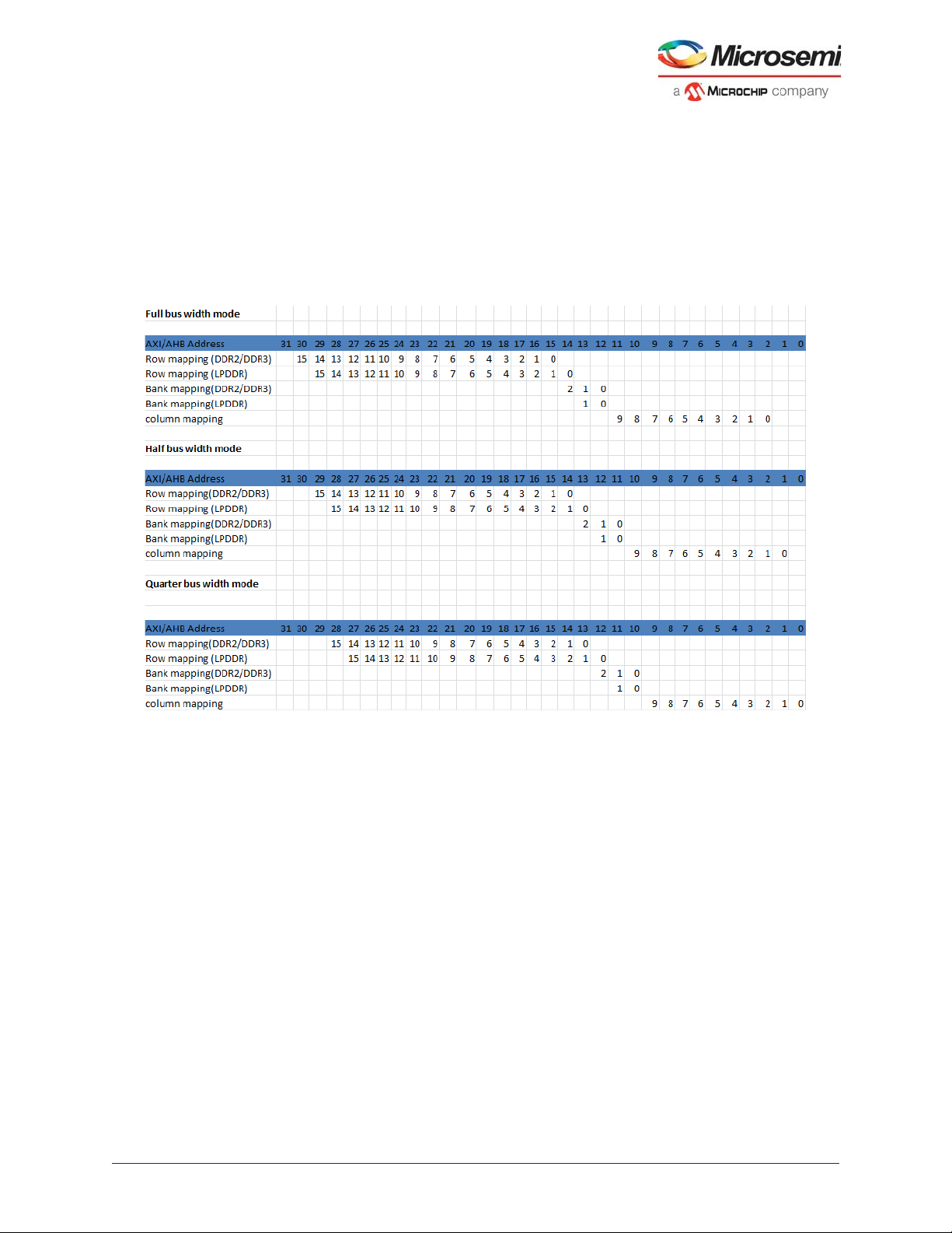
MDDR Subsystem
[Internal base] + [register value] = [source address bit number]
For example, reading the description for REG_DDRC_ADDRMAP_COLB3, the internal base is 3; so
when the full data bus is in use, the column bit 4 is determined by 3+ [register value].
If this register is programmed to 2, then the source address bit is: 3+2 = 5.
The DDR configurator assigns values to the address mapping registers depending on the selected
number of columns, rows and banks. The following illustration provides the default mapping of the
memory row, bank, and column address to the user interface address domain.
Figure 10 • Address Mapping
EQ 1
The following are the address mapping registers:
• DDRC_ADDR_MAP_BANK_CR
• DDRC_ADDR_MAP_COL_1_CR
• DDRC_ADDR_MAP_COL_2_CR
• DDRC_ADDR_MAP_COL_3_CR
• DDRC_ADDR_MAP_ROW_1_CR
• DDRC_ADDR_MAP_ROW_2_CR
While configuring the registers, ensure that two DDR memory address bits are not determined by the
same source address bit.
Note: Some registers map multiple source address bits (REG_DDRC_ADDRMAP_ROW_B0_11).
To arrive at the right address for the DDR controller, the system address or AXI address bits [4:0] are
mapped by the MDDR.
• In full bus width mode, the system address bits [4:0] are used to map the lower column address bits
(C0, C1, C2).
• In half bus width mode, the system address bits [4:0] are used to map the lower column address bits
(C0, C1, C2, C3).
• In quarter bus width mode, the system address bits [4:0] are used to map the lower column address
bits (C0, C1, C2, C3, C4).
The MDDR configurator uses (Row, Bank, and Column) address mapping as shown in the following
example.
Microsemi Proprietary UG0446 User Guide Revision 7.0 28
Page 40

MDDR Subsystem
3.5.5.6.1 Example
In this example, the Address map registers are configured to access a 512 MB DDR3 SDRAM memory
(MT41J512M8RA) from the MDDR subsystem as shown in "Example 2: Connecting 32-Bit DDR3 to
MDDR_PADs with SECDED" section on page 59. The 512M x 8-bit DDR3 memory module has
3 bank address lines, 16 rows, and 10 columns.
• The column address bits 3 to 9 are mapped for system address bit[5] to system address bit[11]. To
map the column 3-bit (C3) to address [5], the field is configured to 3, as the base value is 2. Similarly,
the other column address bits are configured:
• DDRC_ADDR_MAP_COL_1_CR = 0x3333
• DDRC_ADDR_MAP_COL_2_CR = 0x3FFF
• DDRC_ADDR_MAP_COL_3_CR = 0x3300
• The bank address bits 0 to 2 are mapped for system address bit[12] to system address bit[14]. To
map the bank bit0 to address [12], the field is configured to A, as the base value is 2. Similarly, the
other bank address bits are configured:
• DDRC_ADDR_MAP_BANK_CR = 0xAAA
• The row address bits 0 to 15 are mapped for system address bit[15] to system address bit[27]. To
map the bank bit0 to address [15], the field is configured to 9, as the base value is 6. Similarly, the
other bank address bits are configured:
• DDRC_ADDR_MAP_ROW_1_CR = 0x9999
• DDRC_ADDR_MAP_ROW_2_CR = 0x9FF
Note: The MDDR can access the 4 GB address space (0x00000000 - 0xFFFFFFFF). But in this example, 512
MB (0x00000000 - 0x1FFFFFFF) DDR3 SDRAM is connected to the 16 address lines of MDDR. The
memory visible in the other memory space is mirrored of this 512 MB memory.
3.5.5.7 DDR Mode Registers
After reset, the DDR controller initializes the mode registers of DDR memory with the values in the
following registers. The mode registers must be configured according to the specification of the external
DDR memory when the controller is in soft reset.
• DDRC_INIT_MR_CR
• DDRC_INIT_EMR_CR
• DDRC_INIT_EMR2_CR
• DDRC_INIT_EMR3_CR
The T_MOD and T_MRD bits in DDRC_DRAM_MR_TIMING_PARAM_CR must be configured to the
required delay values. T_MOD and T_MRD are delays between loading the mode registers.
3.5.5.8 SECDED
To enable SECDED mode, set the REG_DDRC_MODE bits to 101 in DDRC_MODE_CR. The
PHY_DATA_SLICE_IN_USE_CR register must be configured to enable data slice 4 of the PHY.
The register value REG_DDRC_LPR_NUM_ENTRIES in the performance register,
DDRC_PERF_PARAM_1_CR, must be increased by 1 to the value used in Normal mode (without
SECDED).
Note: MDDR has 36 DQ lines. These data lines are split into the following data slices:
• Data slice0 represents first 8 DQ lines (DQ0 to DQ7)
• Data slice1 represents next 8 DQ lines (DQ8 to DQ15)
• Data slice2 represents next 8 DQ lines (DQ16 to DQ23)
• Data slice3 represents next 8 DQ lines (DQ24 to DQ31)
• Data slice4 represents the remaining 4 DQ lines (DQ32 to DQ35)
3.5.5.9 Read Write Latencies
The read and write latencies between DDR controller and DDR PHY can be configured. Configure the
DDRC_DRAM_RD_WR_LATENCY_CR register for adding latencies for read and writes.
3.5.5.10 Performance
The DDR controller has several performance registers which can be used to increase the speed of the
read and write transactions to DDR memory.
Microsemi Proprietary UG0446 User Guide Revision 7.0 29
Page 41

MDDR Subsystem
The DDR controller has a transaction store, shared for low and high priority transactions. The
DDRC_PERF_PARAM_1_CR register can be configured for allocating the transaction store between the
low and high priority transactions. For example, if the REG_DDRC_LPR_NUM_ENTRIES field is
configured to 0, the controller allocates more time to high priority transactions. The ratio for LPR: HPR is
1:7 (as the transaction store depth is 8).
The DDRC_HPR_QUEUE_PARAM_1_CR, DDRC_LPR_QUEUE_PARAM_1_CR, and
DDRC_WR_QUEUE_PARAM_CR registers can be configured for the minimum clock values for treating
the transactions in the HPR, LPR, and WR queue as critical and non-critical.
To force all incoming transactions to low priority, configure the DDRC_PERF_PARAM_2_CR register. By
default it is configured to force all the incoming transactions to low priority.
3.5.5.11 Refresh Controls
The DDR controller automatically issues refresh commands to DDR memory for every tRFC (min). The
DDR controller can be programmed to issue single refreshes at a time
(REG_DDRC_REFRESH_BURST = 0) to minimize the worst-case impact of a forced refresh cycle. It
can be programmed to burst the maximum number of refreshes allowed for DDR (REFRESH_BURST =
7, for performing 8 refreshes at a time) to minimize the bandwidth lost when refreshing the pages.
3.5.5.12 1T or 2T Timing
The DRAM can be used in 1T or 2T Timing mode by configuring the DDRC_PERF_PARAM_3_CR
register. The address bus can be clocked using 1T or 2T clocking. With 1T, the DDR controller can issue
a new command on every clock cycle. In 2T timing, the DDR controller holds the address and command
bus valid for two clock cycles. This reduces the efficiency of the bus to one command per two clocks, but
it doubles the amount of setup and hold time. The data bus remains the same for all of the variations in
the address bus and the default configuration is 1T timing mode.
3.5.5.13 ODT Controls
The ODT for a specific rank of memory can be enabled or disabled by configuring the
DDRC_ODT_PARAM_1_CR and DDRC_ODT_PARAM_2_CR registers. These must be configured
before taking the controller out of soft reset. They are applied to every read or write issued by the
controller.
3.5.5.14 Soft Resets
Set the REG_DDRC_SOFT_RSTB bit of DDRC_DYN_SOFT_RESET_CR to 0 to reset the DDR
controller. To release the DDR controller from reset, set the REG_DDRC_SOFT_RSTB bit of
DDRC_DYN_SOFT_RESET_ALIAS_CR to 1.
3.5.5.15 MDDR Memory Map
The address map to access the DDR memory from MSS/HPMS masters through MDDR is 0xA00000000xDFFFFFFF, which is 1 GB. But the MDDR can support up to 4 GB of memory, out of which only 1 GB
of this memory is accessible at a time from the MSS/HPMS masters through the AHB bus matrix.
DDR_FIC can access the entire 4 GB memory.
To enable MSS/HPMS masters to access 4 GB, the DDR address space (0x00000000-0xFFFFFFFF) is
divided into 16 DDR regions, as shown in Table 17 on page 31. Each region is 256 MB (4 regions
together form 1 GB). The HPMS masters can access any of these four regions at a time, depending on
the Address Space Mapping mode configured for that particular master using the DDRB_CR register in
SYSREG. For SmartFusion2, the DDRB_CR register has four 4-bit fields
(DDR_IDC_MAP,DDR_SW_MAP, DDR_HPD_MAP, and DDR_DS_MAP). For Igloo2, the DDRB_CR
register has two 4-bit fields (DDR_SW_MAP, DDR_HPD_MAP) whose bits can be configured to select
the DDR Address Space Mapping modes from 0 to 12.
The Address Space Mapping modes for a 4 GB memory are shown in Table 18 on page 31. For example,
if the DDR_SW_MAP is configured as 0001, then the AHB bus matrix can access 0, 1, 2, and 3 regions
Microsemi Proprietary UG0446 User Guide Revision 7.0 30
Page 42

MDDR Subsystem
of DDR that is, the accessible DDR memory from AHB bus matrix is 0x00000000-0x4FFFFFFF which is
1 GB.
Table 17 • DDR Memory Regions
DDR Memory Region DDR Memory Space
0 0×00000000-0×0FFFFFFF
1 0×10000000-0×1FFFFFFF
2 0×20000000-0×2FFFFFFF
3 0×30000000-0×3FFFFFFF
4 0×40000000-0×4FFFFFFF
5 0×50000000-0×5FFFFFFF
6 0×60000000-0×6FFFFFFF
7 0×70000000-0×7FFFFFFF
8 0×80000000-0×8FFFFFFF
9 0×90000000-0×9FFFFFFF
10 0×A0000000-0×AFFFFFFF
11 0×B0000000-0×BFFFFFFF
12 0×C0000000-0×CFFFFFFF
13 0×D0000000-0×DFFFFFFF
14 0×E0000000-0×EFFFFFFF
15 0×F0000000-0×FFFFFFFF
Table 18 • Accessed DDR Memory Regions (Based on Mode Settings for 4 GB Memory)
DDR Memory Regions Visible at MSS/HPMS DDR Address Space for Different Modes
MSS/HPMS DDR
Space 0
Address Space
Mapping Modes
0000 Region 10 Region 11 Region 12 Region 13
0001 Region 0 Region 1 Region 2 Region 3
0010 Region 0 Region 1 Region 2 Region 3
0011 Region 4 Region 5 Region 6 Region 7
0100 Region 8 Region 9 Region 10 Region 11
0101 Region 12 Region 13 Region 14 Region 15
0110 Region 0 Region 1 Region 2 Region 3
0111 Region 0 Region 1 Region 4 Region 5
1000 Region 0 Region 1 Region 6 Region 7
1001 Region 0 Region 1 Region 8 Region 9
1010 Region 0 Region 1 Region 10 Region 11
1011 Region 0 Region 1 Region 12 Region 13
1100 Region 0 Region 1 Region 14 Region 15
(0×A0000000-
0×AFFFFFFF)
MSS/HPMS DDR
Space 1
(0×B00000000×BFFFFFFF)
MSS/HPMS DDR
Space 2
(0×C00000000×CFFFFFFF)
MSS/HPMS DDR
Space 3
(0×D00000000×DFFFFFFF)
Microsemi Proprietary UG0446 User Guide Revision 7.0 31
Page 43

MDDR Subsystem
If 2 GB of DDR memory is connected to MDDR, only 8 regions are available (0-7). The following table
shows the DDR regions available for address mode settings.
Table 19 • Accessed DDR Memory Regions Based on Mode Settings for a 2 GB Memory
DDR Memory Regions Visible at MSS/HPMS DDR Address Space for Different Modes
MSS/HPMS DDR
Space 0
Address Space
Mapping Modes
0000 Region 2 Region 3 Region 4 Region 5
0001 Region 0 Region 1 Region 2 Region 3
0010 Region 0 Region 1 Region 2 Region 3
0011 Region 4 Region 5 Region 6 Region 7
0110 Region 0 Region 1 Region 2 Region 3
0111 Region 0 Region 1 Region 4 Region 5
1000 Region 0 Region 1 Region 6 Region 7
If 1 GB of DDR memory is connected to MDDR, only 4 regions are available (0-4). The following table
shows the DDR regions available for address mode settings.
(0×A0000000-
0×AFFFFFFF)
MSS/HPMS DDR
Space 1
(0×B00000000×BFFFFFFF)
MSS/HPMS DDR
Space 2
(0×C00000000×CFFFFFFF)
MSS/HPMS DDR
Space 3
(0×D00000000×DFFFFFFF)
Table 20 • Accessed DDR Memory Regions Based on Mode Settings for a 1 GB Memory
DDR Memory Regions Visible at HPMS DDR Address Space for Different Modes
MSS/HPMS DDR
Space 0
Address Space
Mapping Modes
0000 Region 2 Region 3 Region 0 Region 1
0001 Region 0 Region 1 Region 2 Region 3
0010 Region 0 Region 1 Region 2 Region 3
(0×A0000000-
0×AFFFFFFF)
MSS/HPMS DDR
Space 1
(0×B00000000×BFFFFFFF)
MSS/HPMS DDR
Space 2
(0×C00000000×CFFFFFFF)
MSS/HPMS DDR
Space 3
(0×D00000000×DFFFFFFF)
3.6 How to Use MDDR in IGLOO2 Device
This section describes how to use MDDR in the IGLOO2 devices. To configure the IGLOO2 device
features and then build a complete system, use the System Builder graphical design wizard in the Libero
Software.
The following image shows the initial System Builder window where you can select the features that you
require. For details on how to launch the System Builder wizard and a detailed information on how to use
it, refer the IGLOO2 System Builder User Guide. You can also use CoreABC based initialization as
described in Igloo2 Standalone Peripheral Initialization User Guide.
Microsemi Proprietary UG0446 User Guide Revision 7.0 32
Page 44

MDDR Subsystem
Figure 11 • System Builder—Device Features Window
For more information about how to use MDDR in the SmartFusion2 devices, refer to "Appendix A: How to
Use the MDDR in SmartFusion2" section on page 112.
3.6.1 Configuring MDDR
The following steps configure the MDDR:
Microsemi Proprietary UG0446 User Guide Revision 7.0 33
Page 45

MDDR Subsystem
1. Check the HPMS External DDR Memory (MDDR) check box under the Device Features tab and
leave the other check boxes unchecked. The following image shows the System Builder - Device
Features tab.
Figure 12 • MDR Initialization Path
2. Selecting the MDDR under HPMS External Memory check box in the System Builder performs the
following actions:
• Instantiates the required IPs like CoreConfigMaster and CoreConfigP that initialize the MDDR
Controller.
• Establishes the initialization path:
CoreConfigMaster → FIC_0 → eNVM → FIC_2 → CoreConfigP → APB bus of the MDDR subsytem
• CoreConfigMaster (AHB Master) accesses the DDR configuration data stored in eNVM through
FIC_0.
• The configuration data is sent to CoreConfigIP through the FIC_2 master port.
• CoreConfigP sends the configuration data to APB bus of the MDDR subsystem.
3. Navigate to the Memories tab. Select the memory settings under the General tab depending on the
application requirement, as shown in Figure 13, page 36.
• Memory type can be selected as DDR2, DDR3, or LPDDR.
• Data width can be selected as 32-bit, 16-bit, or 8-bit. Refer toTable 13 on page 26 for supported data
widths for various IGLOO2 device packages.
• SECDED (ECC) can be enabled or disabled.
• Arbitration Scheme can be selected from Type-0 to Type-3. Refer toTable 10 on page 20 for
arbitration scheme details.
• The highest priority ID of fabric master ranges from 0 to 15 if the selected arbitration scheme is other
than Type-0.
Microsemi Proprietary UG0446 User Guide Revision 7.0 34
Page 46

MDDR Subsystem
• For address mapping, the register settings that perform mapping to system address bits for row,
bank and column combinations are automatically computed by the configurator using the address
mapping option. The following table lists the supported range for row, bank, and column.
Table 21 • Supported Address Width Range for Row, Bank and Column Addressing in DDR/LPDDR
Width DDR2 DDR3 LPDDR
Row Address 12–16 12–16 12–16
Bank Address 2–3 2–3 2–3
Column Address 9–12 9–12 9–12
For more information refer to the "Address Mapping" section.
• Select the I/O Drive Strength as Half Drive Strength or Full Drive Strength, as shown in
Figure 13, page 36. The following table lists how the DDR I/O standard is configured based on this
setting.
Table 22 • DDR I/O Standard is Configured Based on I/O Drive Strength Setting
Memory Type
I/O Drive Strength
Half Drive Strength SSTL18I SSTL15I
Full Drive Strength SSTL18II SSTL15II
DDR2 DDR3
Microsemi Proprietary UG0446 User Guide Revision 7.0 35
Page 47

MDDR Subsystem
Figure 13 • I/O Drive Strength Setting
4. For only LPDDR memory, the I/O standard and I/O calibration settings are available as shown in
the following illustration.
•Select I/O standard as LVCMOS18 or LPDDRI. For the Microsemi M2GL_EVAL_KIT board, select
LPDDRI(SSTL18) because the board is designed to use the LPDDRI I/O standard.
Note: If LVCMOS18 is selected, all I/Os are configured to LVCMOS1.8 except CLK/CLK_N.CLK and CLK_N,
which are configured to the LPDDRI standard because they are differential signals.
•Select I/O calibration as ON or OFF. If I/O calibration is selected as ON, then the IGLOO2
MDDR_IMP_CALIB pin must be pulled down with a resistor. For more information on resistor
values, refer to the Impedance Calibration section in the DS0124: IGLOO2 Pin Descriptions
Datasheet.
Microsemi Proprietary UG0446 User Guide Revision 7.0 36
Page 48

MDDR Subsystem
Figure 14 • Selecting I/O Standard as LVCMOS18 or LPDDRI
5. Depending on the application requirement, select the Memory Initialization settings under the
Memory Initialization tab as shown in Figure 15 on page 39.
• Select the following performance-related settings:
• Burst length can be selected as 4, 8, or 16. Refer toTable 13 on page 26 for supported burst
lengths.
• Burst order can be selected as sequential or interleaved. Refer toTable 13 on page 26 for
supported burst orders.
• Timing mode can be selected as 1T or 2T. For more details, refer to "1T or 2T Timing" section
on page 30.
• CAS latency is the delay in clock cycles between the internal READ command and the
availability of the first bit of output data. Select the CAS latency according to the DDR memory
(mode register) datasheet.
• Select the following power saving mode settings. Refer to "Power Saving Modes" section on
page 24 for more details.
• Self-refresh enabled
• Auto refresh burst count
• Power down enabled
• Stop the clock (supported only for LPDDR)
• Deep power down enabled (supported only for LPDDR)
• Power down entry time
• Select the additional performance settings for DDR3 memory.
• Additive CAS Latency is defined by EMR[5:3] register of DDR2 memory and by MR1[4:3]
register of DDR3 memory. It enables the DDR2 or DDR3 SDRAM to allow a READ or WRITE
Microsemi Proprietary UG0446 User Guide Revision 7.0 37
Page 49

MDDR Subsystem
• Select the following ZQ Calibration settings for DDR3 memory. For more details, refer to "ZQ
• Select the other following settings.
command from DDR Controller after the ACTIVATE command for the same bank prior to tRCD
(MIN). This configuration is part of DDR2 Extended Mode register and DDR3 mode register1.
• CAS Write Latency (CWL) is defined by DDR3 MR2[5:3] and is the delay in clock cycles from
the releasing of the internal write to the latching of the first data in. The overall WRITE latency
(WL) is equal to CWL + AL (by default CWL is set to 5 clock cycles).
Calibration" section on page 17.
•Zqinit
•ZQCS
• ZQCS Interval
• The local ODT setting is not supported for LPDDR memory. For the DDR2/DDR3 memory type,
the user can choose any option for “Local ODT”. User can enable or disable “LOCAL ODT”
during read transaction.
• Drive strength setting is defined by EMR[7:5] register bits of LPDDR memory with drop down
options of `Full', `Half', `Quarter', and `One-eighth' drive strength; EMR[1] register bit of DDR2
memory with drop down options of `Full' and `Weak' drive strength; and MR1 register bits M5
and M1 of DDR3 memory with drop down options of `RZQ/6' and `RZQ/7'.
• The partial array self-refresh coverage setting is defined by EMR[2:0] register bits of LPDDR
memory with drop down options of `Full', `Quarter', `One-eighth', and `One-sixteenth'. This
feature improves power savings by selecting the amount of memory to be refreshed during selfrefresh.
•R
(Nominal) setting is defined by EMR[6] and EMR[2] register bits of DDR2 memory, which
TT
determines what ODT resistance is enabled with drop down options of `RTT disabled', '50
ohms', '75 Ω', and `150 Ω’, and it is defined by MR1[9], MR1[6] and MR1[2] register bits of
DDR3 memory. In DDR3 memory, RTT nominal termination is allowed during standby
conditions and WRITE operations, not during READ operations with drop down options of
`RZQ/2', `RZQ/4' and `RZQ/6'.
•R
_WR (Dynamic ODT) setting is defined by MR2[10:9] register bits of DDR3 memory. This is
TT
applicable only during WRITE operations. If dynamic ODT (Rtt_WR) is enabled, DRAM
switches from normal ODT (R
) to dynamic ODT (Rtt_WR) when beginning WRITE burst
TT_nom
and subsequently switches back to normal ODT at the end of WRITE burst. The drop down
options provided to the user are `off', `RZQ/4', and `RZQ/2'.
• The auto self-refresh setting is defined by MR2[6] register bit of DDR3 memory with drop down
options `Manual' and `Auto'. The self-refresh temperature setting is defined by MR2[7] register
bit of DDR2 memory with drop down options of `Normal' and `Extended'.
Microsemi Proprietary UG0446 User Guide Revision 7.0 38
Page 50

MDDR Subsystem
Figure 15 • Memory Initialization Configuration
6. Select the memory timing settings under the Memory Timing tab according to the DDR memory
vendor datasheet, as shown in the following image. For more details, refer to "Configuring Dynamic
DRAM Constraints" section on page 26.
Microsemi Proprietary UG0446 User Guide Revision 7.0 39
Page 51

MDDR Subsystem
Figure 16 • Memory Timing Configuration
The configurator also provides the option to import and export the register configurations. The
configuration settings are stored in eNVM. Configuration files for accessing LPDDR memory on IGLOO2
evaluation kit can be downloaded from:
www.microsemi.com/soc/documents/LPDDR_Emcraft_Config.zip.
The following is an example of MDDR register configurations for operating the LPDDR memory
(MT46H64M16LF) with clock 166 MHz.
• Device Memory Settling Time (µs): 200
The DDR memories require settling time for the memory to initialize before accessing it. The LPDDR
memory model MT46H64M16LF needs 200 µs settling time.
• General
• Memory Type: LPDDR
• Data Width: 16
• Memory Initialization
• Burst length: 8
• Burst Order: Interleaved
• Timing Mode: 1T
• CAS Latency: 3
• Self Refresh Enabled: No
• Auto Refresh Burst Count: 8
• PowerDown Enabled: Yes
• Stop the clock: No
Microsemi Proprietary UG0446 User Guide Revision 7.0 40
Page 52

MDDR Subsystem
• Deep PowerDown enabled: No
• No Activity clocks for Entry: 320
• Memory Timing
• Time To Hold Reset Before INIT: 67584 clks
• MRD: 4 clks
• RAS (Min): 8 clks
• RAS (Max): 8192 clks
• RCD: 6 clks
• RP: 7 clks
• REFI: 3104 clks
• RC: 3 clks
• XP: 3 clks
• CKE: 3 clks
• RFC: 79 clks
• FAW: 0 clks
7. Navigate to the Peripherals tab. The Peripherals tab allows configuration of the Fabric AMBA
Master and Fabric AMBA Slave required for the design. Drag and drop the required master/slave to
the corresponding subsystem. The following image shows the Peripherals tab. Drag and drop the
Fabric Master core to the HPMS DDR FIC Subsystem. This allows to the interface to be
configured as AXI or single AHB-Lite. On completing the configuration, the selected interface is
enabled. The user logic in the FPGA fabric can access the DDR memory through the MDDR using
these interfaces.
Figure 17 • System Builder - Peripherals Tab
8. Navigate to the Clocks tab. The Clocks tab allows configuration of the System Clock and
subsystem clocks.The MDDR subsystem operates on MDDR_CLK, which comes from HPMS_CCC.
Microsemi Proprietary UG0446 User Guide Revision 7.0 41
Page 53

MDDR Subsystem
The MDDR_CLK must be selected as multiples of 1, 2, 3, 4, 6, or 8 of HPMS_CLK. This clock can
be configured using the HPMS_CCC configurator. The maximum frequency of MDDR_CLK is
333.33 MHz. The following illustration shows the MDDR_CLK configuration.
Figure 18 • MDDR_CLK Configuration
DDR_FIC_CLK drives the DDR_FIC slave interface and defines the frequency at which the FPGA fabric
subsystem connected to this interface is intended to run. DDR_FIC_CLK can be configured as a ratio of
MDDR_CLK (1, 2, 3, 4, 6, 8, 12, 16, or 32) using the Clocks configurator. The maximum frequency of
DDR_FIC_CLK is 200 MHz. The following illustration shows the DDR_FIC_CLK configuration.
Figure 19 • DDR_FIC_CLK Configuration
If the MDDR_CLK ratio to HPMS_CLK is a multiple of 3, DDR_FIC_CLKs ratio to MDDR_CLK must also
be a multiple of 3, and vice versa. The configuration issues an error if this requirement is not met. This
limitation is imposed by the internal implementation of the HPMS CCC.
3.6.1.1 I/O Configuration
In the I/O Editor window, as shown in the following illustration, configure I/O settings such as ODT and
drive strength.
Microsemi Proprietary UG0446 User Guide Revision 7.0 42
Page 54

MDDR Subsystem
Figure 20 • I/O Editor Window
3.6.2 Accessing MDDR from FPGA Fabric through the AXI Interface
The AXI master in the FPGA fabric accesses the DDR memory through the MDDR subsystem. The
following illustration shows the MDDR subsystem with the AXI interface. The MDDR registers are
configured from the FPGA fabric using the CoreConfigMaster IP through the CoreConfigP IP APB
interface.
Microsemi Proprietary UG0446 User Guide Revision 7.0 43
Page 55

MDDR Subsystem
Figure 21 • MDDR with AXI Interfaces
HPMS
DDR
SDRAM
D
D
D
D
R
I
O
R
P
H
Y
AXI
DDR
Controller
Master
Slave 1
AXI
Transaction
Controller
APB Config
Reg
Slave n
MDDR
DDR_FIC
HPMS DDR
Bridge
AHB Bus Matrix
FIC_0 FIC_1
AHB
CoreConfigMaster
HPDMA
eNVM
APB_2
CoreConfigP
Fabric
IGLOO2
Read, write, and read-modify-write transactions are initiated by the AXI master to read from or write the
data to the DDR memory after initializing the MDDR registers.
The following steps describe how to access the MDDR from AXI master in the FPGA fabric:
Microsemi Proprietary UG0446 User Guide Revision 7.0 44
Page 56

MDDR Subsystem
1. Go to the System Builder - Device Features tab, check the HPMS External DDR Memory check
box, and select MDDR. Leave the rest of the check boxes unchecked. The following illustration
shows the System Builder - Device Features tab.
Figure 22 • System Builder - Device Features Tab
2. Configure the HPMS External Memory in the Memories tab as shown in the following illustration. In
this example, the design is created to access DDR3 memory with a 32-bit data width and no ECC.
3. Set the DDR memory settling time to 200 us and click Import Register Configuration.
Figure 23 • Memory Configuration
4. Navigate to the Peripherals tab.
5. In the Peripherals tab, drag the Fabric Master Core and drop on to the HPMS DDR FIC
Subsystem. You can see that the master is added to the subsystem. The following image shows the
Peripherals tab with the AMBA_MASTER_0 added.
6. Click the Configure icon to open the AMBA Master - Configuration dialog. The following image
shows the Peripherals tab with the Configure icon highlighted.
Microsemi Proprietary UG0446 User Guide Revision 7.0 45
Page 57

MDDR Subsystem
Figure 24 • Peripherals Tab with the Master Added and Configure Icon Highlighted
7. In the Configuring AMBA_MASTER_0 dialog, select the Interface Type as AXI and then click OK.
The following image shows the AMBA Master - Configuration dialog.
Figure 25 • AMBA Master Configuration
8. Configure the System Clock and Subsystem clocks in the Clocks tab. The following image shows
the Clocks configuration dialog.
• Select the On-chip 25/50 MHz RC oscillator.
•Configure HPMS_CCC for MDDR_CLK and DDR_FIC_CLK.
9. Configure HPMS_CLK, DDR_FIC_CLK, APB_0_CLK, FIC_0_CLK to 111 MHz and MDDR clock
as 333 MHz.
Microsemi Proprietary UG0446 User Guide Revision 7.0 46
Page 58

MDDR Subsystem
Figure 26 • System Clocks Configuration
10. Navigate to the Memory Map tab giving the required data in the rest of the System Builder tabs.
11. Instantiate your AXI master logic in the SmartDesign canvas to access the MDDR subsystem
through the AXI interface. Ensure that the AXI master logic accesses the MDDR after configuring the
MDDR registers (INIT_DONE indicates the successful MDDR initialization).
12. Connect the AXI_Master logic signals as follows:
• RESET_N to INIT_DONE
• CLK to HPMS_DDR_FIC_SUBSYSTEM_CLK
• LOCK to HPMS_DDR_FIC_SUBSYSTEM_LOCK
• AXI_S_RMW to MDDR_DDR_AXI_S_RMW
The following illustration shows the rest of the connections in the top level design.
Microsemi Proprietary UG0446 User Guide Revision 7.0 47
Page 59

MDDR Subsystem
Figure 27 • SmartDesign Connections (Top Level View)
For MDDR AXI throughput, see AC422: SmartFusion2 - Optimizing DDR Controller for Improved
Efficiency - Libero v11.7 Application Note.
3.6.3 Accessing MDDR from FPGA Fabric Through the AHB Interface
The MDDR subsystem can be used to access the DDR memory using the AHB-Lite interface. The
following illustration shows the MDDR with AHB-Lite interface.
Microsemi Proprietary UG0446 User Guide Revision 7.0 48
Page 60

MDDR Subsystem
FIC_0 FIC_1
AHB Bus Matrix
D
D
R
I
O
Fabric
HPMS DDR
Bridge
IGLOO2
DDR
Controller
D
D
R
P
H
Y
APB Config
Reg
MDDR
AXI
Transaction
Controller
DDR_FIC
HPDMA
HPMS
DDR
SDRAM
AHB
CoreConfigMaster
APB_2
CoreConfigP
eNVM
AHB_Lite
Slave 1
Slave n
Master
Figure 28 • MDDR with Single AHB-Lite Interface
The procedure for accessing the MDDR from AHB master in the FPGA fabric is the same as in
"Accessing MDDR from FPGA Fabric through the AXI Interface" section on page 43—except for the
following:
• Configure the AMBA Master Interface Type as AHB-Lite in the HPMS DDR FIC Subsystem in the
Peripherals tab of the System Builder wizard.
Table 23, page 49 lists the MDDR throughput for the following configuration:
• Fabric Interface: AHB
• MDDR Mode: DDR3
• Fabric Clock to MDDR Clock Ratio: 1:4
• PHY Width: 16 and 32
• Clock Frequency: 80 MHz
The other parameters are configured similar to the MDDR configuration in AC422: SmartFusion2 -
Optimizing DDR Controller for Improved Efficiency - Libero v11.7 Application Note.
Table 23 • MDDR Throughput (for AHB)
MDDR-Fabric
Interface-Memory
MDDR_AHB-DDR3
Frequency Ratio
CLK_BASE:FDDR_CLK)PHY Width
(
80 MHz:320 MHz
1:4
PHY_16 80 MB 79 MB
PHY_32 80 MB 79 MB
Write Transaction BW
(MB/sec)
Read Transaction BW
(MB/sec)
Microsemi Proprietary UG0446 User Guide Revision 7.0 49
Page 61

MDDR Subsystem
3.6.4 Accessing MDDR from the HPDMA
The HPDMA controller can access DDR SDRAM connected to the MDDR subsystem through the HPMS
DDR bridge. The following illustration shows the MDDR with HPDMA.
Figure 29 • MDDR with HPDMA
HPMS
D
DDR
SDRAM
D
D
R
I
O
D
R
P
H
Y
DDR
Controller
AXI
Tr ansaction
Controller
APB Config
Reg
IGLOO2
The following steps describe how to access the MDDR from HPDMA:
1. Open the System Builder - Device Features tab. Check the HPMS External DDR Memory check
box, select MDDR and HPMS High Performance DMA (HPDMA) check boxes, leaving the rest of
the check boxes unchecked. The following image shows the System Builder - Device Features
tab.
Figure 30 • System Builder - Device Features Tab
MDDR
HPMS DDR
Bridge
FIC_0 FIC_1
AHB
CoreConfigMaster
HPDMA
eNVM
AHB Bus Matrix
APB_2
CoreConfigP
eSRAM
Fabric
2. Configure the HPMS External Memory in Memories tab. as shown in the following image. In this
example, the design is created to access the DDR3 memory with a 32-bit data width and no ECC.
3. Set the DDR memory settling time to 200 us and click Import Register Configuration.
Microsemi Proprietary UG0446 User Guide Revision 7.0 50
Page 62

MDDR Subsystem
Figure 31 • Memory Configurations
4. Configure the System Clock and Subsystem clocks in the Clocks tab. The following image shows
the Clocks configuration dialog.
• Select the On-chip 25/50 MHz RC Oscillator
•Configure HPMS_CCC for MDDR_CLK
5. Configure HPMS_CLK, APB_0_CLK, FIC_0_CLK clocks as 111 MHz and the MDDR_CLK clock
as 333 MHz.
Figure 32 • Clocks Configuration
6. Navigate to the Memory Map tab giving the required data in the rest of the System Builder tabs.
For more Information on how to use HPDMA, refer to the HPDMA chapter in UG0448: IGLOO2 High
Performance Memory Subsystem User Guide.
Microsemi Proprietary UG0446 User Guide Revision 7.0 51
Page 63
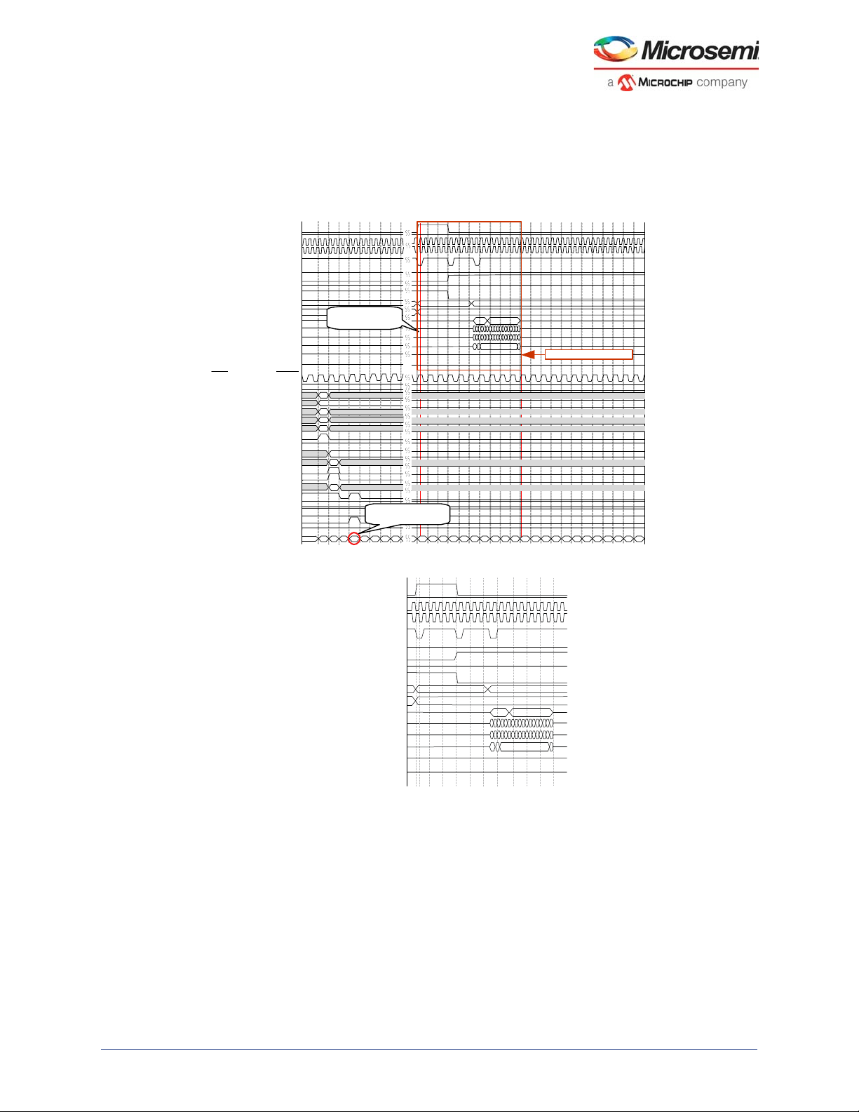
MDDR Subsystem
0000 0008
0
0400
1
0
0
0
0
0
0
0
1
ff
1
3
MDDR_CAS_N
MDDR_CKE
MDDR_CLK
MDDR_CLK_N
MDDR_CS_N
MDDR_ODT
MDDR_RAS_N
MDDR_RESET_N
MDDR_WE_N
MDDR_ADDR
MDDR_BA
MDDR_DM_RDQS
MDDR_DQS
MDDR_DQS_N
MDDR_DQ
MDDR_DQS_TMATCH_0_IN
MDDR_DQS_TMA TCH_0_OUT
CLK
AWID
AWADDR
AWLEN
AWSIZE
AWLOCK
AWBURS T
AWVALID
AWREADY
WID
WSTRB
WLAST
WVALID
WDATA
WREADY
BID
BRESP
BVALI D
BREADY
CLK_CO UNT
DDR write controls
55 56 57 58 59 60 61 62 63 64 65 66
67 686970 71 72 73 74 75
76
13468
52
7
0
0
00000 00000
333333333
3333
3 3
3
333
00000000
10
CLK Cycle s for completi ng
AXI transaction
Write transaction to DDR
Memory initiated by MDDR
0
Refer Figure 1-34 on Page 60
3.7 Timing Diagrams
This section shows the operation of the DDR controller with AXI interface with Timing diagrams. The
DDR3 16-bit micron memory model is used to perform the read and write transactions from MDDR
Fabric Interface (DDR_FIC). The AXI/AHB clock is configured for 166 MHz and MDDR clock is
configured for 332 MHz, that is, FIC clock to MDDR clock ratio is 1:2.
Figure 33 • AXI Single Write Transaction and Corresponding DDR Controller Commands
Figure 34 • DDR Controller Command Sequence for Single AXI Write Transaction
MDDR_CAS_N
MDDR_CKE
MDDR_CLK
MDDR_CLK_N
MDDR_CS_N
MDDR_ODT
MDDR_RAS_N
MDDR_RESET_N
MDDR_WE_N
0008
00000 00000
3333
00000000
0
0
10
MDDR_ADDR
MDDR_BA
MDDR_DM_RDQS
MDDR_DQS
MDDR_DQS_N
MDDR_DQS_TMATCH_0_IN
MDDR_DQ
0000
0
MDDR_DQS_TMATCH_0_OUT
Microsemi Proprietary UG0446 User Guide Revision 7.0 52
3
333333333
33333
Page 64

MDDR Subsystem
Read transacon to DDR
Memory iniated by MDDR
023
4
1
6785 10
11 12914 15 1613 18 19
20
17
22 23 2421
26 27 2825
30
31
3233
29
55
54
0000
0
000800010 0018 0020 0028 00380030
56
58 59 60
57
62 63 6461
66 67 6865
70 71 7269
74 75 7673
78 79 877
0
0
0
1
0400
3
1
0
0
1
23 45678 9 10 11 12 13 14 15
16
MDDR_CLK
MDDR_CLK_N
MDDR_CS_N
MDDR_ODT
MDDR_CKE
MDDR_CAS_N
MDDR_RAS_N
MDDR_RESET_N
MDDR_WE_N
MDDR_ADDR
MDDR_BA
MDDR_DM_RDQS
MDDR_DQS
MDDR_DQS_N
MDDR_DQ
MDDR_DQS_TMATCH_0_IN
MDDR_DQS_TMATCH_0_OUT
mddr_dqs_tmatch_0_out
CLK
AWADDR
AWID
AWLEN
AWSIZE
AWLOCK
AWBURST
AWVALID
AWREADY
WID
BID
WLAST
WSTRB
WVALID
WDATA
WREADY
BREADY
BVALID
RESP
DDR write controls
0
0
f
Refer Figure 1-34 on page 55
Refer Figure 1-33 on page 55
ss
ss
ss
ss
ss
ss
ss
ss
ss
ss
ss
ss
ss
ss
ss
ss
ss
ss
ss
ss
ss
Figure 35 • AXI Single Read Transaction and Corresponding DDR Controller Commands
MDDR_CLK_N
MDDR_CS_N
MDDR_ODT
MDDR_RAS_N
MDDR_RESET_N
MDDR_WE_N
MDDR_ADDR
0000
MDDR_BA
MDDR_DM_RDQS
MDDR_DQS_N
MDDR_DQS_TMATCH_0_IN
MDDR_DQS_TMATCH_0_OUT
DDR read controls
10
MDDR_DQS
MDDR_DQ
ARADDR
ARSIZE
ARLOCK
ARBURST
ARVALID
ARREADY
RVALID
RREADY
CLK_CNT
ARID
ARLEN
RDATA
RLAST
RRESP
CLK
0
00000000
0
3
0
1
RID
0
0
0
234
1
567
0
3
9
8
10 11 12 13 14 15
0
00333
33
0000
333
00
11
0
CLK Cycles for compleng
transacon
16 17 18 19 20
Figure 36 • AXI INCR16 Write Transaction and Corresponding DDR Controller Commands
1
Microsemi Proprietary UG0446 User Guide Revision 7.0 53
Write transacon to
DDR Memory iniated
CLK Cycles for compleng
transacon
Page 65

MDDR Subsystem
0
023
4
1
6785 10 11 129 14 15 1613 18 19 20
17
22 23 2421
26 27 2825
30 31 3229
3433
0
0
0
0
f
0
3
1
1
2345678 9 10 11 12 13 14 15
16
0
CLK
AWADDR
AWID
AWLEN
AWSIZE
AWLOCK
AWBURST
AWVALID
AWREADY
WID
BID
WLAST
WSTRB
WVALID
WDATA
WREADY
BREADY
BVALID
RESP
DDR write controls
0000
0
0008
000000000
00000
0010
0018
0020
0028 0038
0030
MDDR_CLK
MDDR_CLK_N
MDDR_CS_N
MDDR_ODT
MDDR_CKE
MDDR_CAS_N
MDDR_RAS_N
MDDR_RESET_N
MDDR_WE_N
MDDR_ADDR
MDDR_BA
MDDR_DM_RDQS
MDDR_DQS
MDDR_DQS_N
MDDR_DQ
MDDR_DQS_TMATCH_0_IN
MDDR_DQS_TMATCH_0_OUT
mddr_dqs_tmatch_0_out
00
000
0000
0000000000
0
0
0
00 0 0 0 0 0 0 0 0 0 0 0 0 0 0
0000000
0000000
000
0000
0000000000
3
123456789101112131415
16
3333333
3333333
333
3333
333333333333
33333333
3333333
333
3333
3333333333
y
Figure 37 • AXI INCR16 Write Transaction
Figure 38 • DDR Controller Command Sequence for AXI INCR16 Write Transaction
Figure 39 • AXI INCR-16 Read Transaction and Corresponding DDR Controller Commands
MDDR_CAS_N
MDDR_CKE
MDDR_CLK
MDDR_CLK_N
MDDR_CS_N
MDDR_ODT
MDDR_RAS_N
MDDR_RESET_N
MDDR_WE_N
0000
MDDR_ADDR
MDDR_BA
MDDR_DM_RDQS
MDDR_DQS
MDDR_DQS_N
MDDR_DQ
MDDR_DQS_TMATCH_0_IN
MDDR_DQS_TMATCH_0_OUT
mddr_dqs_tmatch_0_out
DDR write controls
ARBURST
00
CLK
ARID
0
ARADDR
0
00000000
f
ARLEN
00000000
ARSIZE
3
ARLOCK
0
0
1
ARVALID
ARREADY
0
RID
RDATA
RVALID
RLAST
RREADY
RESP
0
CLK_CNT
0
Read transacon to
DDR Memor
2341
856
7
Microsemi Proprietary UG0446 User Guide Revision 7.0 54
0008
iniated
0000000000 000000
10
14
11 129
13 18
0010
0018
0020
1
19 20
15 16
17
0028
0030
0038
Refer Figure 1-36
2 3 4 5 6 7 8 9 10 11 12 13 14 15 16
25 26 27 28 29 30 31 32 33 34 35 36 37 38 39 40 41 42 43 44 45 46 47 48 49 50
22 23 2421
CLK Cycles for compleng
transacon
Page 66

MDDR Subsystem
00
0000000000 000000
0000
0008
0010
0018
0020
0028
0030
0038
MDDR_CLK
MDDR_CLK_N
MDDR_CS_N
MDDR_ODT
MDDR_CKE
MDDR_CAS_N
MDDR_RAS_N
MDDR_RESET_N
MDDR_WE_N
MDDR_ADDR
MDDR_BA
MDDR_DM_RDQS
MDDR_DQS
MDDR_DQS_N
MDDR_DQ
MDDR_DQS_TMATCH_0_IN
MDDR_DQS_TMATCH_0_OUT
mddr_dqs_tmatch_0_out
y
Figure 40 • DDR Controller Command Sequence for AXI INCR-16 Read Transaction
Read transacon to
DDR Memor
iniated
The following table summarizes the number of cycles to complete the AXI/AHB transactions to MDDR.
Table 24 • Number of Cycles for AXI/AHB Transactions to MDDR
Transaction Type Write Cycles Read Cycles
AXI Single 4 19
AXI INCR16 Burst 31 49
3.8 Timing Optimization Technique for AXI
The AXI mode of the MDDR or FDDR provides the highest throughput interface to the external memory
device. The best interface ratio for clocking is 2:1 ratio which keeps the fabric clock and fabric interface
running at the same rate as the external memory device. For these types of interfaces the following
technique provides an optimization method for timing closure when using the 2:1 interface. Timing
closure can be achieved by Timing Optimization Technique when the timing closure is not met with the
design.
The optimization method can reside between an existing AXI master and the DDR_FIC AXI slave
interface and no changes are required to the AXI master design. The following illustration shows a
diagram of the technique, which uses a negative edge register on the VALID lines.
Microsemi Proprietary UG0446 User Guide Revision 7.0 55
Page 67

MDDR Subsystem
DDR_FIC_SUBSYSTEM_CLK
Fabric AXI
Master
MDDR/FDDR
DDR_FIC
WVALID
ARVALID
AWVALID
WREADY
ARREADY
FCCC
System Builder
Generated Component
Other AXI signals
AXI RESET
AWREADY
xVALID_new
Address/
data
AXI CLK
xVALID
xREADY
Data Transfer on
xVALID/xREADY
handshake
Figure 41 • AXI Timing Optimization Logic
The AXI data lines into the DDR_FIC can now be relaxed with additional half AXI clock cycle as the AXI
valid signals are delayed by half AXI clock cycle. The following illustration shows the AXI transaction with
the optimization logic.
Figure 42 • Timing Diagram
The following SDC constraints need to be added to the timing SDC file. It applies the proper timing
relaxation on the DDR_FIC_AXI signals.
For FDDR:
/* The following constraints provide a relaxation constraint on the signals of 1.5 clock periods.
The user should adjust the ddr_clock_frequency to match their application. */
set ddr_clock_frequency 333
set delay1 [ expr 3000/$ddr_clock_frequency ]
set_max_delay $delay1 -to [ get_pins { \
Microsemi Proprietary UG0446 User Guide Revision 7.0 56
Page 68

MDDR Subsystem
*/INST_FDDR_IP:F_ARADDR* \
*/INST_FDDR_IP:F_ARBURST* \
*/INST_FDDR_IP:F_ARID* \
*/INST_FDDR_IP:F_ARLEN*\
*/INST_FDDR_IP:F_ARLOCK* \
*/INST_FDDR_IP:F_ARSIZE* \
*/INST_FDDR_IP:F_AWADDR* \
*/INST_FDDR_IP:F_AWBURST* \
*/INST_FDDR_IP:F_AWID* \
*/INST_FDDR_IP:F_AWLEN* \
*/INST_FDDR_IP:F_AWLOCK* \
*/INST_FDDR_IP:F_AWSIZE* \
*/INST_FDDR_IP:F_WDATA* \
*/INST_FDDR_IP:F_WID* \
*/INST_FDDR_IP:F_WLAST \
*/INST_FDDR_IP:F_WSTRB* \
*/INST_FDDR_IP:F_BREADY* \
*/INST_FDDR_IP:F_RMW_AXI \
*/INST_FDDR_IP:F_RREADY* \
} ]
/* The following constraints provide a relaxation constraint on the signals of 1 clock period. */
set delay2 [ expr 2000/$ddr_clock_frequency ]
set_max_delay $delay2 -to [ get_pins { \
*/INST_FDDR_IP:F_ARVALID* \
*/INST_FDDR_IP:F_AWVALID* \
*/INST_FDDR_IP:F_WVALID \
} ]
For MDDR:
/* The following constraints provide a relaxation constraint on the signals of 1.5 clock periods.
The user should adjust the ddr_clock_frequency to match their application. */
set ddr_clock_frequency 333
set delay1 [ expr 3000/$ddr_clock_frequency ]
set_max_delay1 $delay1 -to [ get_pins { \
*/INST_MSS_*_IP:F_ARADDR* \
*/INST_MSS_*_IP:F_ARBURST* \
*/INST_MSS_*_IP:F_ARID* \
*/INST_MSS_*_IP:F_ARLEN*\
*/INST_MSS_*_IP:F_ARLOCK* \
Microsemi Proprietary UG0446 User Guide Revision 7.0 57
Page 69

MDDR Subsystem
*/INST_MSS_*_IP:F_ARSIZE* \
*/INST_MSS_*_IP:F_AWADDR* \
*/INST_MSS_*_IP:F_AWBURST* \
*/INST_MSS_*_IP:F_AWID* \
*/INST_MSS_*_IP:F_AWLEN* \
*/INST_MSS_*_IP:F_AWLOCK* \
*/INST_MSS_*_IP:F_AWSIZE* \
*/INST_MSS_*_IP:F_WDATA* \
*/INST_MSS_*_IP:F_WID* \
*/INST_MSS_*_IP:F_WLAST \
*/INST_MSS_*_IP:F_WSTRB* \
*/INST_MSS_*_IP:F_BREADY \
*/INST_MSS_*_IP:F_RMW_AXI \
*/INST_MSS_*_IP:F_RREADY \
} ]
/* The following constraints provide a relaxation constraint on the signals of 1 clock period. */
set delay2 [ expr 2000/$ddr_clock_frequency ]
set_max_delay $delay2 -to [ get_pins { \
*/INST_MSS_*_IP:F_ARVALID* \
*/INST_MSS_*_IP:F_AWVALID* \
*/INST_MSS_*_IP:F_WVALID \
} ]
3.9 DDR Memory Device Examples
This section describes how to connect DDR memories to IGLOO2 MDDR_PADs with examples.
Note: For more information on requirement of termination resistors, refer to the Datasheets/Application Notes
of the memory manufacturers.
3.9.1 Example 1: Connecting 32-Bit DDR2 to MDDR_PADs
The following illustratoin shows DDR2 SDRAM connected to the MDDR of a IGLOO2 device. Micron’s
MT47H64M16 is a 128 MB density device with x16 data width. The MDDR is configured in full bus width
mode and without SECDED. The total amount of DDR2 memory connected to MDDR is 256 MB.
Microsemi Proprietary UG0446 User Guide Revision 7.0 58
Page 70

MDDR Subsystem
Figure 43 • x16 DDR2 SDRAM Connected to MDDR
MDDR_PADS
MDDR_CAS_N
MDDR_CKE
MDDR_CLK
MDDR_CLK_N
MDDR_CS_N
MDDR_IMP_CALIB
R
MDDR_DM_RDQS[1:0]
MDDR_DM_RDQS[3:2]
MDDR_DQS_TMATCH_0_IN
MDDR_DQS_TMATCH_0_OUT
MDDR_DQS_TMATCH_1_IN
MDDR_DQS_TMATCH_1_OUT
MDDR_ODT
MDDR_RAS_N
MDDR_WE_N
MDDR_ADDR[12:0]
MDDR_BA[2:0]
MDDR_DQS[1:0]
MDDR_DQS_N[1:0]
MDDR_DQ[15:0] DQ[15:0]
MDDR_DQS[3:2]
MDDR_DQS_N[3:2]
MDDR_DQ[31:16]
MT47H64M16
CASN
CKE
CLK_P
CLK_N
CSN
ODT
RASN
WEN
ADDR[12:0]
BA[2:0]
DM
UDQS, LDQS
UDQS#, LDQS#
MT47H64M16
CASN
CKE
CLK_P
CLK_N
CSN
ODT
RASN
WEN
ADDR[12:0]
BA[2:0]
DM
UDQS, LDQS
UDQS#, LDQS#
DQ[15:0]
3.9.2 Example 2: Connecting 32-Bit DDR3 to MDDR_PADs with SECDED
The following illustration shows DDR3 SDRAM connected to the MDDR of a IGLOO2 device. Micron’s
MT41J512M8RA is a 512 MB density device with x8 data width. The MDDR is configured in full bus width
mode with SECDED enabled. The SDRAM connected to MDDR_DQ_ECC[3:0] is used to store
SECDED bits. The total amount of DDR3 memory (excluding memory for SECDED) connected to MDDR
is 2 GB.
Microsemi Proprietary UG0446 User Guide Revision 7.0 59
Page 71

MDDR Subsystem
CASN
CKE
CLK_P
CLK_N
CSN
ODT
RASN
RSTN
WEN
ADDR[15:0]
BA[2:0]
MT41J512M8RA
MDDR_CAS_N
MDDR_CKE
MDDR_CLK
MDDR_CLK_N
MDDR_CS_N
MDDR_ODT
MDDR_RAS_N
MDDR_RESET_N
MDDR_WE_N
MDDR_ADDR[15:0]
MDDR_BA[2:0]
MDDR_DM_RDQS[0]
MDDR_DQS[0]
MDDR_DQS_N[0]
MDDR_DQ[7:0]
MDDR_DM_RDQS[1]
MDDR_DQS[1]
MDDR_DQS_N[1]
MDDR_DQ[15:8]
MDDR_DM_RDQS[2]
MDDR_DQS[2]
MDDR_DQS_N[2]
MDDR_DQ[23:16]
MDDR_DM_RDQS[3]
MDDR_DQS[3]
MDDR_DQS_N[3]
MDDR_DQ[31:24]
MDDR_DM_RDQS_ECC
MDDR_DQS_ECC
MDDR_DQS_ECC_N
MDDR_DQ_ECC[3:0]
DQ[7:0]
DQS#
DQS
DM
MT41J512M8RA
MT41J512M8RA
MT41J512M8RA
MT41J512M8RA
ZQ
ZQ
ZQ
ZQ
ZQ
MDDR_PADS
DQ[7:0]
DQS#
DQS
DM
DQ[7:0]
DQS#
DQS
DM
DQ[7:0]
DQS#
DQS
DM
DQ[3:0]
DQS#
DQS
DM
MDDR_IMP_CALIB
R
MDDR_DQS_TMATCH_0_IN
MDDR_DQS_TMATCH_0_OUT
MDDR_DQS_TMATCH_1_IN
MDDR_DQS_TMATCH_1_OUT
MDDR_DQS_TMATCH_ECC_IN
MDDR_DQS_TMATCH_ECC_OUT
Figure 44 • ×8 DDR3 SDRAM Connection to MDDR
3.9.3 Example 3: Connecting 16-Bit LPDDR to MDDR_PADs with SECDED
The following illustration shows LPDDR1 SDRAM connected to the MDDR of a IGLOO2 device. The
micron’s MT46H32M16LF is a 64 MB density device with x16 data width. The MDDR is configured in full
bus width mode with SECDED enabled. The SDRAM connected to MDDR_DQ_ECC[1:0] is used to
store SECDED bits. The total amount of LPDDR1 memory (excluding memory for SECDED) connected
to MDDR is 64 MB.
Microsemi Proprietary UG0446 User Guide Revision 7.0 60
Page 72

MDDR Subsystem
CASN
CKE
CLK_P
CLK_N
CSN
RASN
WEN
ADDR[12:0]
BA[2:0]
MT46H32M16LF
MDDR_CAS_N
MDDR_CKE
MDDR_CLK
MDDR_CLK_N
MDDR_CS_N
MDDR_RAS_N
MDDR_WE_N
MDDR_ADDR[12:0]
MDDR_BA[1:0]
MDDR_DM_RDQS[1:0]
MDDR_DQS[0]
MDDR_DQ[15:0] DQ[15:0]
UDQS
LDQS
UDM, LDM
CASN
CKE
CLK_P
CLK_N
CSN
RASN
WEN
ADDR[12:0]
BA[2:0]
MT46H32M16LF
DQ[1:0]
LDQS
LDM
MDDR_DM_RDQS_ECC
MDDR_DQS_ECC
MDDR_DQ_ECC[1:0]
MDDR_DQS[1]
MDDR_PADS
MDDR_DQS_TMATCH_0_IN
MDDR_DQS_TMATCH_0_OUT
MDDR_IMP_CALIB
R
MDDR_DQS_TMATCH_ECC_IN
MDDR_DQS_TMATCH_ECC_OUT
Figure 45 • ×16 LPDDR1 SDRAM Connection to MDDR
3.10 Board Design Considerations
Table 25 • I/O Standards and Calibration Resistance Requirements for MDDR/FDDR
Memory Type IO Standard Calibration Resistor
LPDDR LVCMOS18
DDR2 SSTL18 Required
DDR3 SSTL15 Required
Note: For LVCMOS18 IO Standard, the user can optionally calibrate the IO. If calibration is desired, the user
3.11 MDDR Configuration Registers
MDDR/FDDR subsystems are interfaced with DDR memories through DDRIO. DDRIO is a multistandard IO optimized for LPDDR, DDR2, and DDR3 performance. The following table lists the IO
standards and calibration resistance requirements for MDDR/FDDR to interface with DDR memories.
LPDDRI(SSTL18)
For more information on IO Standards and Calibration Resistance Requirements, refer to the
AC394: Layout Guidelines for SmartFusion2/IGLOO2-Based Board Design Application Note and
AC393: Board Design Guidelines for SmartFusion2 SoC and IGLOO2 FPGA Application Note.
Not Required*
Required
must install the appropriate resistor on the PCB.
This section provides MDDR subsystem registers along with the address offset, functionality, and bit
definitions. The registers are categorized based on the controller blocks in the MDDR subsystem.
Microsemi Proprietary UG0446 User Guide Revision 7.0 61
Page 73

MDDR Subsystem
The following table lists the categories of registers and their offset addresses. The base address of the
MDDR subsystem registers is 0x40020800.
Table 26 • Address Table for Register Interfaces
Registers Address Offset Space
DDR Controller Configuration Register 0×000:0×1FC
Reserved 0×200:0×3FC
DDR_FIC Configuration Register Summary 0×400:0×4FC
Reserved 0×500:0×7FC
3.11.1 SYSREG Configuration Register Summary
In addition to the specific MDDR subsystem registers, the registers listed in the following table also
control the behavior of the MDDR subsystem. These registers are located in the SYSREG section of the
user's guide and are listed here for convenience. Refer to the “System Register Block” in the UG0448:
IGLOO2 High Performance Memory Subsystem User Guide for a detailed description of each register
and associated bits.
Table 27 • SYSREG Configuration Register Summary
Flash
Register
Register Name
MDDR_CR RW-P Register PORESET_N MDDR Configuration register
MDDR_IO_CALIB_CR RW-P Register PORESET_N MDDR I/O Calibration Control
HPMSDDR_PLL_STATUS_LOW_CR RW-P Register CC_RESET_N Used to control the corresponding
HPMSDDR_PLL_STATUS_HIGH_CR RW-P Register CC_RESET_N Used to control the corresponding
HPMSDDR_FACC1_CR RW-P Field CC_RESET_N HPMS DDR Fabric Alignment Clock
HPMSDDR_FACC2_CR RW-P Field CC_RESET_N HPMS DDR Fabric Alignment Clock
HPMSDDR_CLK_CALIB_STATUS RW-P Register SYSRESET_N Used to start an FPGA fabric
DDRB_CR RW-P Register SYSRESET_N HPMS DDR bridge configuration
HPMSDDR_PLL_STATUS RO – – HPMS DDR PLL Status register
MDDR_IO_CALIB_STATUS RO – PORESET_N DDR I/O Calibration Status register
HPMSDDR_CLK_CALIB_STATUS RO – SYSRESET_N HPMS DDR Clock Calibration Status
SOFT_RESET_CR RW-P Bit SYSRESET_N Soft reset control register
Type
Write
Protect Reset Source Description
register
configuration input of the MPLL.
configuration input of the MPLL
register
Controller 1 Configuration register
Controller 2 Configuration register
calibration test circuit.
register
register
Microsemi Proprietary UG0446 User Guide Revision 7.0 62
Page 74

MDDR Subsystem
3.11.2 DDR Controller Configuration Register Summary
Table 28 • DDR Controller Configuration Register
Addres
Register Name
DDRC_DYN_SOFT_RESET_CR 0×000 RW/RO PRESET_N DDRC Reset register
DDRC_DYN_REFRESH_1_CR 0×008 RW PRESET_N DDRC Refresh Control
DDRC_DYN_REFRESH_2_CR 0×00C RW PRESET_N DDRC Refresh Control
DDRC_DYN_POWERDOWN_CR 0×010 RW PRESET_N DDRC Power-Down Control
Reserved 0×014 - - -
DDRC_MODE_CR 0×018 RW PRESET_N DDRC Mode register
DDRC_ADDR_MAP_BANK_CR 0×01C RW PRESET_N DDRC Bank Address Map
Reserved 0×020 - - -
DDRC_ADDR_MAP_COL_1_CR 0×024 RW PRESET_N DDRC Column Address
DDRC_ADDR_MAP_COL_2_CR 0×028 RW PRESET_N DDRC Column Address
DDRC_ADDR_MAP_ROW_1_CR 0×02C RW PRESET_N DDRC Row Address Map
DDRC_ADDR_MAP_ROW_2_CR 0×030 RW PRESET_N DDRC Row Address Map
DDRC_INIT_1_CR 0×034 RW PRESET_N DDRC Initialization Control
DDRC_CKE_RSTN_CYCLES_1_CR 0×038 RW PRESET_N DDRC Initialization Control
DDRC_ CKE_RSTN_CYCLES_2_CR 0×03C RW PRESET_N DDRC Initialization Control
DDRC_INIT_MR_CR 0×040 RW PRESET_N DDRC MR Initialization
DDRC_INIT_EMR_CR 0×044 RW PRESET_N DDRC EMR Initialization
DDRC_INIT_EMR2_CR 0×048 RW PRESET_N DDRC EMR2 Initialization
DDRC_INIT_EMR3_CR 0×04C RW PRESET_N DDRC EMR3 Initialization
DDRC_DRAM_BANK_TIMING_PARAM_CR 0×050 RW PRESET_N DDRC DRAM Bank Timing
DDRC_DRAM_RD_WR_LATENCY_CR 0×054 RW PRESET_N DDRC DRAM Write Latency
DDRC_DRAM_RD_WR_PRE_CR 0×058 RW PRESET_N DDRC DRAM Read-Write
s Offset
Registe
r Type
Reset
Source Description
register
register
register
register
Map register
Map register
register
register
register
register
register
register
register
register
register
Parameter register
register
Precharge Timing register
Microsemi Proprietary UG0446 User Guide Revision 7.0 63
Page 75

MDDR Subsystem
Table 28 • DDR Controller Configuration Register (continued)
Addres
Register Name
DDRC_DRAM_MR_TIMING_PARAM_CR 0×05C RW PRESET_N DDRC DRAM Mode
DDRC_DRAM_RAS_TIMING_CR 0×060 RW PRESET_N DDRC DRAM RAS Timing
DDRC_DRAM_RD_WR_TRNARND_TIME_CR 0×064 RW PRESET_N DDRC DRAM Read Write
DDRC_DRAM_T_PD_CR 0×068 RW PRESET_N DDRC DRAM Power-Down
DDRC_DRAM_BANK_ACT_TIMING_CR 0×06C RW PRESET_N DDRC DRAM Bank Activate
DDRC_ODT_PARAM_1_CR 0×070 RW PRESET_N DDRC ODT Delay Control
DDRC_ODT_PARAM_2_CR 0×074 RW PRESET_N DDRC ODT Hold/Block
DDRC_ADDR_MAP_COL_3_CR 0×078 RW PRESET_N Upper byte is DDRC
DDRC_MODE_REG_RD_WR_CR 0×07C RW PRESET_N DDRC Mode Register
DDRC_MODE_REG_DATA_CR 0×080 RW PRESET_N DDRC Mode Register Write
DDRC_PWR_SAVE_1_CR 0×084 RW PRESET_N DDRC Power Save register
DDRC_PWR_SAVE_2_CR 0×088 RW PRESET_N DDRC Power Save register
DDRC_ZQ_LONG_TIME_CR 0×08C RW PRESET_N DDRC ZQ Long Time
DDRC_ZQ_SHORT_TIME_CR 0×090 RW PRESET_N DDRC ZQ Short Time
DDRC_ZQ_SHORT_INT_REFRESH_MARGIN_1_CR 0×094 RW PRESET_N DDRC ZQ Short Time
DDRC_ZQ_SHORT_INT_REFRESH_MARGIN_2_CR 0×098 RW PRESET_N DDRC ZQ Short Time
DDRC_PERF_PARAM_1_CR 0×09C RW PRESET_N DDRC Performance
DDRC_HPR_QUEUE_PARAM_1_CR 0×0A0 RW PRESET_N DDRC Performance
DDRC_HPR_QUEUE_PARAM_2_CR 0×0A4 RW PRESET_N DDRC Performance
DDRC_LPR_QUEUE_PARAM_1_CR 0×0A8 RW PRESET_N DDRC Performance
DDRC_LPR_QUEUE_PARAM_2_CR 0×0AC RW PRESET_N DDRC Performance
s Offset
Registe
r Type
Reset
Source Description
Register Timing Parameter
register
Parameter register
Turn-around Timing register
Parameter register
Timing Parameter register
register
cycles register
Column Address Map
register and lower byte
controls debug features.
Read/ Write Command
register
Data Register
Calibration register
Calibration register
Calibration register
Calibration register
Parameter register
Parameter register
Parameter register
Parameter register
Parameter register
Microsemi Proprietary UG0446 User Guide Revision 7.0 64
Page 76

MDDR Subsystem
Table 28 • DDR Controller Configuration Register (continued)
Addres
Register Name
DDRC_WR_QUEUE_PARAM_CR 0×0B0 RW PRESET_N DDRC Performance
DDRC_PERF_PARAM_2_CR 0×0B4 RW PRESET_N DDRC Performance
DDRC_PERF_PARAM_3_CR 0×0B8 RW PRESET_N DDRC Performance
DDRC_DFI_RDDATA_EN_CR 0×0BC RW PRESET_N DDRC DFI Read Command
DDRC_DFI_MIN_CTRLUPD_TIMING_CR 0×0C0 RW PRESET_N DDRC DFI Controller
DDRC_DFI_MAX_CTRLUPD_TIMING_CR 0×0C4 RW PRESET_N DDRC DFI Controller
Reserved - - - Reserved - - - Reserved - - - Reserved - - - Reserved - - - -
DDRC_DYN_SOFT_RESET_ALIAS_CR 0×0DC RW PRESET_N DDRC reset register
DDRC_AXI_FABRIC_PRI_ID_CR 0×0E0 RW PRESET_N DDRC AXI Interface Fabric
DDRC_SR 0×0E4 RO PRESET_N DDRC Status register
SECDED Registers
DDRC_SINGLE_ERR_CNT_STATUS_SR 0×0E8 RO PRESET_N DDRC single error count
DDRC_DOUBLE_ERR_CNT_STATUS_SR 0×0EC RO PRESET_N DDRC double error count
DDRC_LUE_SYNDROME_1_SR 0×0F0 RO PRESET_N DDRC last uncorrected
DDRC_LUE_SYNDROME_2_SR 0×0F4 RO PRESET_N DDRC last uncorrected
DDRC_LUE_SYNDROME_3_SR 0×0F8 RO PRESET_N DDRC last uncorrected
DDRC_LUE_SYNDROME_4_SR 0×0FC RO PRESET_N DDRC last uncorrected
DDRC_LUE_SYNDROME_5_SR 0×100 RO PRESET_N DDRC last uncorrected
DDRC_LUE_ADDRESS_1_SR 0×104 RO PRESET_N DDRC last uncorrected
DDRC_LUE_ADDRESS_2_SR 0×108 RO PRESET_N DDRC last uncorrected
DDRC_LCE_SYNDROME_1_SR 0×10C RO PRESET_N DDRC last corrected error
s Offset
Registe
r Type
Reset
Source Description
Parameter register
Parameter register
Parameter register
Timing register
Update Min Time register
Update Max Time register
Priority ID Register
Status register
status register
error syndrome register
error syndrome register
error syndrome register
error syndrome register
error syndrome register
error address register
error address register
syndrome register
Microsemi Proprietary UG0446 User Guide Revision 7.0 65
Page 77

MDDR Subsystem
Table 28 • DDR Controller Configuration Register (continued)
Addres
Register Name
DDRC_LCE_SYNDROME_2_SR 0×110 RO PRESET_N DDRC last corrected error
DDRC_LCE_SYNDROME_3_SR 0×114 RO PRESET_N DDRC last corrected error
DDRC_LCE_SYNDROME_4_SR 0×118 RO PRESET_N DDRC last corrected error
DDRC_LCE_SYNDROME_5_SR 0×11C RO PRESET_N DDRC last corrected error
DDRC_LCE_ADDRESS_1_SR 0×120 RO PRESET_N DDRC last corrected error
DDRC_LCE_ADDRESS_2_SR 0×124 RO PRESET_N DDRC last corrected error
DDRC_LCB_NUMBER_SR 0×128 RO PRESET_N DDRC last corrected bit
DDRC_LCB_MASK_1_SR 0×12C RO PRESET_N DDRC last corrected bit
DDRC_LCB_MASK_2_SR 0×130 RO PRESET_N DDRC last corrected bit
DDRC_LCB_MASK_3_SR 0×134 RO PRESET_N DDRC last corrected bit
DDRC_LCB_MASK_4_SR 0×138 RO PRESET_N DDRC last corrected bit
DDRC_ECC_INT_SR 0×13C RO PRESET_N DDRC SECDED interrupt
DDRC_ECC_INT_CLR_REG 0×140 RW PRESET_N DDRC SECDED interrupt
s Offset
Registe
r Type
Reset
Source Description
syndrome register
syndrome register
syndrome register
syndrome register
address register
address register
number register
mask status register
mask status register
mask status register
mask status register
status register
clear register
Microsemi Proprietary UG0446 User Guide Revision 7.0 66
Page 78

MDDR Subsystem
3.11.3 DDR Controller Configuration Register Bit Definitions
Table 29 • DDRC_DYN_SOFT_RESET_CR
Bit
Number Name
[31:3] Reserved 0×0 Software should not rely on the value of a reserved
2 AXIRESET 0×1 Set when main AXI reset signal is asserted. Reads
1 RESET_APB_REG 0×0 Full soft reset
0 REG_DDRC_SOFT_RSTB 0×0 This is a soft reset.
Table 30 • DDRC_DYN_REFRESH_1_CR
Reset
Value Description
bit. To provide compatibility with future products, the
value of a reserved bit should be preserved across a
read-modify-write operation.
and writes to the dynamic registers should not be
carried out. This is a read only bit.
If this bit is set when the soft reset bit is written as 1,
all APB registers reset to the power-up state.
0: Puts the controller into reset.
1: Takes the controller out of reset.
The controller should be taken out of reset only when
all other registers have been programmed.
Asserting this bit does NOT reset all the APB
configuration registers. Once the soft reset bit is
asserted, the APB register should be modified as
required.
Bit
Number Name
[31:15] Reserved 0×0 Software should not rely on the value of a reserved
[14:7] REG_DDRC_T_RFC_MIN 0×23 t
6 REG_DDRC_REFRESH_UPDATE_LEVEL 0×0 Toggle this signal to indicate that the refresh
5 REG_DDRC_SELFREF_EN 0×0 If 1, then the controller puts the DRAM into self
[4:0] REG_DDRC_REFRESH_TO_X32 0×8 Speculative refresh
Table 31 • DDRC_DYN_REFRESH_2_CR
Bit
Number Name
Reset
Value Description
bit. To provide compatibility with future products, the
value of a reserved bit should be preserved across a
read-modify-write operation.
RFC(min)
activate (specification: 75 ns to 195 ns).
Unit: clocks.
register(s) have been updated.
The value is automatically updated when exiting soft
reset, so it does not need to be toggled initially.
refresh when the transaction store is empty.
Reset
Value Description
– Minimum time from refresh to refresh or
Microsemi Proprietary UG0446 User Guide Revision 7.0 67
Page 79

MDDR Subsystem
Table 31 • DDRC_DYN_REFRESH_2_CR
[31:15] Reserved 0×0 Software should not rely on the value of a reserved bit.
To provide compatibility with future products, the value of
a reserved bit should be preserved across a readmodify-write operation.
[14:3] REG_DDRC_T_RFC_NOM_X32 0×52 t
: Average time between refreshes (specification: 7.8
REFI
µs). Unit: multiples of 32 clocks.
[2:0] REG_DDRC_REFRESH_BURST 0×0 The programmed value plus one is the number of refresh
timeouts that is allowed to accumulate before traffic is
blocked and the refreshes are forced to execute. Closing
pages to perform a refresh is a one-time penalty that
must be paid for each group of refreshes; therefore,
performing refreshes in a burst reduces the per-refresh
penalty of these page closings.
Higher numbers for burst_of_N_refresh slightly
increases utilization; lower numbers decreases the
worst-case latency associated with refreshes.
0x0: Single refresh
0x1: Burst-of-2
0x7: Burst-of-8 refresh
Table 32 • DDRC_DYN_POWERDOWN_CR
Bit
Number Name
Reset
Value Description
[31:2] Reserved 0×0 Software should not rely on the value of a reserved bit.
To provide compatibility with future products, the value of
a reserved bit should be preserved across a read-modifywrite operation.
1 REG_DDRC_POWERDOWN_EN 0×1 If true, the controller goes into power-down after a
programmable number of cycles
(REG_DDRC_POWERDOWN_TO_X32).
This register bit may be reprogrammed during the course
of normal operation.
0 REG_DDRC_DEEPPOWERDOWN_EN 0×0 1: Controller puts the DRAM into deep power-down mode
when the transaction store is empty.
0: Brings controller out of deep power-down mode.
Present only in designs that have mobile support.
Table 33 • DDRC_MODE_CR
Bit
Number Name
Reset
Value Description
[31:9] Reserved 0×0 Software should not rely on the value of a reserved bit. To
provide compatibility with future products, the value of a
reserved bit should be preserved across a read-modify-write
operation.
8 REG_DDRC_DDR3 0×0 1: DDR3 operating mode
0: DDR2 operating mode
Microsemi Proprietary UG0446 User Guide Revision 7.0 68
Page 80

MDDR Subsystem
Table 33 • DDRC_MODE_CR
7 REG_DDRC_MOBILE 0×0 1: Mobile/LPDDR1 DRAM device in use
0: Non-mobile DRAM device in use
6 REG_DDRC_SDRAM 0×0 1: SDRAM mode
0: Non-SDRAM mode. Only present in designs that support
SDRAM and/or mSDR devices.
5 REG_DDRC_TEST_MODE 0×0 1: Controller is in test mode
0: Controller is in normal mode
[4:2] REG_DDRC_MODE 0×0 DRAM SECDED mode
000: No SECDED
101: SECDED enabled
All other selections are reserved.
[1:0] REG_DDRC_DATA_BUS_WIDTH 0×0 00: Full DQ bus width to DRAM
01: Half DQ bus width to DRAM
10: Quarter DQ bus width to DRAM
11: Reserved
Note: The half bus width modes are only supported
when the DRAM bus width is a multiple of 16.
Table 34 • DDRC_ADDR_MAP_BANK_CR
Bit
Number Name
[31:12] Reserved 0×0 Software should not rely on the value of a reserved bit. To
[11:8] REG_DDRC_ADDRMAP_BANK_B0 0×0 Selects the address bits used as bank address bit 0. Valid
[7:4] REG_DDRC_ADDRMAP_BANK_B1 0×0 Selects the address bits used as bank address bit 1. Valid
[3:0] REG_DDRC_ADDRMAP_BANK_B2 0×0 Selects the address bits used as bank address bit 2. Valid
Reset
Value Description
provide compatibility with future products, the value of a
reserved bit should be preserved across a read-modifywrite operation.
Range: 0 to 14
Internal Base: 2
The selected address bit for each of the bank address bits
is determined by adding the internal base to the value of
this field.
Range: 0 to 14
Internal Base: 3
The selected address bit for each of the bank address bits
is determined by adding the internal base to the value of
this field.
Range: 0 to 14 and 15
Internal Base: 4
The selected address bit is determined by adding the
internal base to the value of this field. If set to 15, bank
address bit 2 is set to 0.
Microsemi Proprietary UG0446 User Guide Revision 7.0 69
Page 81

MDDR Subsystem
Table 35 • DDRC_ADDR_MAP_COL_1_CR
Bit
Number Name
[31:16] Reserved 0×0 Software should not rely on the value of a reserved bit. To
[15:12] REG_DDRC_ADDRMAP_COL_B2 0×0 Full bus width mode: Selects column address bit 3.
[11:8] REG_DDRC_ADDRMAP_COL_B3 0×0 Full bus width mode: Selects column address bit 4.
[7:4] REG_DDRC_ADDRMAP_COL_B4
[3:0] REG_DDRC_ADDRMAP_COL_B7
Reset
Value Description
provide compatibility with future products, the value of a
reserved bit should be preserved across a read-modify-write
operation.
Half bus width mode: Selects column address bit 4.
Quarter bus width mode: Selects column address bit 5.
Valid range: 0 to 7
Internal base: 2
The selected address bit is determined by adding the
internal base to the value of this field.
Half bus width mode: Selects column address bit 5.
Quarter bus width mode: Selects column address bit 6.
Valid range: 0 to 7
Internal base: 3
The selected address bit is determined by adding the
internal base to the value of this field.
0×0 Full bus width mode: Selects column address bit 5.
Half bus width mode: Selects column address bit 6.
Quarter bus width mode: Selects column address bit 7.
Valid Range: 0 to 7
Internal base: 4
The selected address bit for each of the column address bits
is determined by adding the internal base to the value of this
field.
0×0 Full bus width mode: Selects column address bit 8.
Half bus width mode: Selects column address bit 9.
Quarter bus width mode: Selects column address bit 11.
Valid range: 0 to 7, and 15
Internal base: 7
The selected address bit is determined by adding the
internal base to the value of this field. If set to 15, column
address bit 9 is set to 0.
Note: Per JEDEC DDR2 specification, column
address bit 10 is reserved for indicating autoprecharge, and hence no source address bit
can be mapped to column address bit 10.
Table 36 • DDRC_ADDR_MAP_COL_2_CR
Bit
Number Name
[31:16] Reserved 0×0 Software should not rely on the value of a reserved bit. To
Microsemi Proprietary UG0446 User Guide Revision 7.0 70
Reset
Value Description
provide compatibility with future products, the value of a
reserved bit should be preserved across a read-modify-write
operation.
Page 82

MDDR Subsystem
Table 36 • DDRC_ADDR_MAP_COL_2_CR
[15:12] REG_DDRC_ADDRMAP_COL_B8 0×0 Full bus width mode: Selects column address bit 9.
Half bus width mode: Selects column address bit 11.
Quarter bus width mode: Selects column address bit 12.
Valid range: 0 to 7, and 15
Internal base: 8
The selected address bit is determined by adding the
internal base to the value of this field. If set to 15, column
address bit 9 is set to 0.
Note: Per JEDEC DDR2 specification, column
address bit 10 is reserved for indicating autoprecharge, and hence no source address bit
can be mapped to column address bit 10.
[11:8] REG_DDRC_ADDRMAP_COL_B9 0×0 Full bus width mode: Selects column address bit 11.
Half bus width mode: Selects column address bit 12.
Quarter bus width mode: Selects column address bit 13.
Valid range: 0 to 7, and 15
Internal base: 9
The selected address bit is determined by adding the
internal base to the value of this field. If set to 15, column
address bit 9 is set to 0.
[7:4] REG_DDRC_ADDRMAP_COL_B100×0 Full bus width mode: Selects column address bit 12.
Half bus width mode: Selects column address bit 13.
Quarter bus width mode: Unused. Should be set to 15.
Valid range: 0 to 7, and 15
Internal base: 10
The selected address bit is determined by adding the
internal base to the value of this field. If set to 15, column
address bit 10 is set to 0.
[3:0] REG_DDRC_ADDRMAP_COL_B11 0×0 Full bus width mode: Selects column address bit 13.
Half bus width mode: Unused. To make it unused, this
should be tied to 0xF.
Quarter bus width mode: Unused. To make it unused, this
should be tied to 0xF.
Valid range: 0 to 7, and 15
Internal base: 11
The selected address bit is determined by adding the
internal base to the value of this field. If set to 15, column
address bit 11 is set to 0.
Table 37 • DDRC_ADDR_MAP_ROW_1_CR
Bit
Number Name
[31:16] Reserved 0×0 Software should not rely on the value of a reserved bit.
Microsemi Proprietary UG0446 User Guide Revision 7.0 71
Reset
Value Description
To provide compatibility with future products, the value of
a reserved bit should be preserved across a readmodify-write operation.
Page 83

MDDR Subsystem
Table 37 • DDRC_ADDR_MAP_ROW_1_CR
[15:12] REG_DDRC_ADDRMAP_ROW_B0 0×0 Selects the address bits used as row address bit 0.
Valid range: 0 to 11
Internal base: 6
The selected address bit for each of the row address bits
is determined by adding the internal base to the value of
this field.
[11:8] REG_DDRC_ADDRMAP_ROW_B1 0×0 Selects the address bits used as row address bit 1.
Valid range: 0 to 11
Internal base: 7
The selected address bit for each of the row address bits
is determined by adding the internal base to the value of
this field.
[7:4] REG_DDRC_ADDRMAP_ROW_B2_11 0×0 Selects the address bits used as row address bits 2 to
11.
Valid Range: 0 to 11
Internal Base: 8 for row address bit 2
9 for row address bit 3
10 for row address bit 4
····
15 for row address bit 9
16 for row address bit 10
17 for row address bit 11
The selected address bit for each of the row address bits
is determined by adding the internal base to the value of
this field.
[3:0] REG_DDRC_ADDRMAP_ROW_B12
0×0 Selects the address bit used as row address bit 12.
Valid Range: 0 to 11, and 15
Internal Base: 18
The selected address bit is determined by adding the
internal base to the value of this field.
If set to 15, row address bit 12 is set to 0.
Table 38 • DDRC_ADDR_MAP_ROW_2_CR
Bit
Number Name
[31:12] Reserved 0×0 Software should not rely on the value of a reserved bit. To
[11:8] REG_DDRC_ADDRMAP_ROW_B13 0×0 Selects the address bits used as row address bit 13.
[7:4] REG_DDRC_ADDRMAP_ROW_B14 0×0 Selects the address bit used as row address bit 14.
Microsemi Proprietary UG0446 User Guide Revision 7.0 72
Reset
Value Description
provide compatibility with future products, the value of a
reserved bit should be preserved across a read-modifywrite operation.
Valid range: 0 to 11, and 15
Internal base: 19
The selected address bit is determined by adding the
internal base to the value of this field.
If set to 15, row address bit 13 is set to 0.
Valid range: 0 to 11, and 15
Internal base: 20
The selected address bit is determined by adding the
internal base to the value of this field.
If set to 15, row address bit 14 is set to 0.
Page 84

MDDR Subsystem
Table 38 • DDRC_ADDR_MAP_ROW_2_CR
[3:0] REG_DDRC_ADDRMAP_ROW_B15 0×0 Selects the address bit used as row address bit 15.
Valid range: 0 to 11, and 15
Internal base: 21
The selected address bit is determined by adding the
internal base to the value of this field.
If set to 15, row address bit 15 is set to 0.
Table 39 • DDRC_INIT_1_CR
Bit
Number Name
[31:12] Reserved 0×0 Software should not rely on the value of a reserved bit. To
[11:8] REG_DDRC_PRE_OCD_X32 0×0 Wait period before driving the on chip driver calibration
[7:1] REG_DDRC_FINAL_WAIT_X32 0×0 Cycles to wait after completing the DRAM initialization
0 REG_DDRC_SKIP_OCD 0×1 This register must be kept at 1.
Reset
Value Description
provide compatibility with future products, the value of a
reserved bit should be preserved across a a read-modifywrite operation.
(OCD) Complete command to DRAM.
Units are in counts of a global timer that pulses every 32
clock cycles.
There is no known specific requirement for this. It may be
set to zero.
sequence before starting the dynamic scheduler.
Units are in counts of a global timer that pulses every 32
clock cycles.
There is known specific requirement for this; it may be set to
zero.
1: Indicates the controller is to skip the on chip driver
calibration (OCD) adjustment step during DDR2
initialization. OCD_Default and OCD_Exit are performed
instead.
0: Not supported
Table 40 • DDRC_CKE_RSTN_CYCLES_1_CR
Bit
Number Name
[31:16] Reserved 0×0 Software should not rely on the value of a reserved bit. To
Microsemi Proprietary UG0446 User Guide Revision 7.0 73
Reset
Value Description
provide compatibility with future products, the value of a
reserved bit should be preserved across a read-modify-write
operation.
Page 85

MDDR Subsystem
Table 40 • DDRC_CKE_RSTN_CYCLES_1_CR
[15:8] REG_DDRC_PRE_CKE_X1024 0×0 The 10-bit REG_DDRC_PRE_CKE_X1024 [9:0] value is
spit across the two registers:
DDRC_CKE_RSTN_CYCLES_1_CR and
DDRC_CKE_RSTN_CYCLES_2_CR.
[7:0] bits of REG_DDRC_PRE_CKE_X1024.
Cycles to wait after reset before driving CKE High to start
the DRAM initialization sequence.
Units: 1,024 clock cycles.
DDR2 specifications typically require this to be programmed
for a delay of
[7:0] REG_DDRC_DRAM_RSTN_X1024 0×0 Number of cycles to assert DRAM reset signal during
initialization sequence.
This is only present for implementations supporting DDR3
devices.
Table 41 • DDRC_ CKE_RSTN_CYCLES_2_CR
≥ 200 µs.
Bit
Number Name
[31:16] Reserved 0×0 Software should not rely on the value of a reserved bit. To
[11:2] REG_DDRC_POST_CKE_X1024 0×0 Cycles to wait after driving CKE High to start the DRAM
[1:0] REG_DDRC_PRE_CKE_X1024 0×0 This field represents the upper 2 bits of the 10-bit
Reset
Value Description
provide compatibility with future products, the value of a
reserved bit should be preserved across a read-modify-write
operation.
initialization sequence.
Units: 1,024 clocks.
DDR: Typically requires a 400 ns delay, requiring this value
to be programmed to 2 at all clock speeds.
SDR: Typically requires this to be programmed for a delay of
100 µs to 200 µs.
REG_DDRC_PRE_CKE_X1024 value split across the 2
registers DDRC_CKE_RSTN_CYCLES_1_CR and
DDRC_CKE_RSTN_CYCLES_2_CR.
[9:8] bits of REG_DDRC_PRE_CKE_X1024.
Cycles to wait from the start of reset assertion before driving
CKE High to start the DRAM initialization sequence.
Units: 1,024 clock cycles.
DDR2 specifications typically require this to be programmed
for a delay of
≥ 200 µs.
Table 42 • DDRC_INIT_MR_CR
Bit
Number Name
[31:16] Reserved 0×0 Software should not rely on the value of a reserved bit. To
Microsemi Proprietary UG0446 User Guide Revision 7.0 74
Reset
Value Description
provide compatibility with future products, the value of a
reserved bit should be preserved across a read-modify-write
operation.
Page 86

MDDR Subsystem
Table 42 • DDRC_INIT_MR_CR
[15:0] REG_DDRC_MR 0×095A Value to be loaded into the DRAM Mode register. Bit 8 is for
the DLL and the setting here is ignored. The controller sets
appropriately. During DRAM initialization procedure, the
controller will send the mode register setting to DRAM. The
mode register sets the DRAM burst length, burst type, CAS
latency (CL), and operating mode.
Table 43 • DDRC_INIT_EMR_CR
Bit
Number Name
[31:16] Reserved 0×0 Software should not rely on the value of a reserved bit. To
[15:0] REG_DDRC_EMR 0×0402 Value to be loaded into DRAM EMR registers. Bits [9:7] are
Table 44 • DDRC_INIT_EMR2_CR
Bit
Number Name
[31:16] Reserved 0×0 Software should not rely on the value of a reserved bit. To provide
[15:0] REG_DDRC_EMR2 0×0 Value to be loaded into DRAM EMR2 registers.
Table 45 • DDRC_INIT_EMR3_CR
Reset
Value Description
Reset
Value Description
provide compatibility with future products, the value of a
reserved bit should be preserved across a read-modify-write
operation.
for OCD and the setting in this bits is ignored.
The controller sets those bits appropriately.
compatibility with future products, the value of a reserved bit should be
preserved across a read-modify-write operation.
Bit
Number Name
[31:16] Reserved 0×0 Software should not rely on the value of a reserved bit. To provide
[15:0] REG_DDRC_EMR3 0×0 Value to be loaded into DRAM EMR3 registers.
Table 46 • DDRC_DRAM_BANK_TIMING_PARAM_CR
Bit
Number Name
[31:12] Reserved 0×0 Software should not rely on the value of a reserved bit. To provide
Reset
Value Description
compatibility with future products, the value of a reserved bit should be
preserved across a read-modify-write operation.
Reset
Value Description
compatibility with future products, the value of a reserved bit should be
preserved across a read-modify-write operation.
Microsemi Proprietary UG0446 User Guide Revision 7.0 75
Page 87

MDDR Subsystem
Table 46 • DDRC_DRAM_BANK_TIMING_PARAM_CR
[11:6] REG_DDRC_T_RC 0×0 tRC: Minimum time between activates to same bank (specification: 65 ns
for DDR2-400 and smaller for faster parts). Unit: clocks.
[5:0] REG_DDRC_T_FAW 0×0 t
: Valid only in burst-of-8 mode.
FAW
At most 4 banks must be activated in a rolling window of tFAW cycles.
Unit: clocks
Table 47 • DDRC_DRAM_RD_WR_LATENCY_CR
Bit
Number Name
Reset
Value Description
[31:10] Reserved 0×0 Software should not rely on the value of a reserved bit. To
provide compatibility with future products, the value of a
reserved bit should be preserved across a read-modify-write
operation.
[9:5] REG_DDRC_WRITE_LATENCY 0×0 Number of clocks between the write command to write data
enable PHY.
[4:0] REG_DDRC_READ_LATENCY 0×0 Time from read command to read data on DRAM interface.
Unit: clocks
This signal is present for designs supporting LPDDR1 DRAM
only. It is used to calculate when the DRAM clock may be
stopped.
Table 48 • DDRC_DRAM_RD_WR_PRE_CR
Bit
Number Name
Reset
Value Description
[31:10] Reserved 0×0 Software should not rely on the value of a reserved bit. To provide
compatibility with future products, the value of a reserved bit should be
preserved across a read-modify-write operation.
[9:5] REG_DDRC_WR2PRE 0×0 Minimum time between write and precharge to same bank
(specifications: WL + BL/2 + tWR = approximately 8 cycles + 15 ns = 14
clocks @ 400 MHz and less for lower frequencies).
Unit: Clocks
where:
WL = Write latency
BL = Burst length. This must match the value programmed in the BL bit
of the mode register to the DRAM.
= Write recovery time. This comes directly from the DRAM specs.
t
WR
[4:0] REG_DDRC_RD2PRE 0×0 t
– Minimum time from read to precharge of same bank
RTP
(specification: tRTP for BL = 4 and tRTP + 2 for BL = 8. tRTP = 7.5 ns).
Unit: clocks.
Table 49 • DDRC_DRAM_MR_TIMING_PARAM_CR
Bit
Number Name
Reset
Value Description
Microsemi Proprietary UG0446 User Guide Revision 7.0 76
Page 88

MDDR Subsystem
Table 49 • DDRC_DRAM_MR_TIMING_PARAM_CR
[31:13] Reserved 0×0 Software should not rely on the value of a reserved bit. To provide
compatibility with future products, the value of a reserved bit should be
preserved across a read-modify-write operation.
[12:3] REG_DDRC_T_MOD 0×0 Present for DDR3 only (replaces REG_DDRC_T_MRD functionality
when used with DDR3 devices). The mode register set command
updates delay in number of clock cycles.
This is required to be programmed even when a design that supports
DDR3 is running in DDR2 mode (minimum is the larger of 12 clock
cycles or 15 ns).
[2:0] REG_DDRC_T_MRD 0×0 t
: Cycles between load mode commands.
MRD
Not used in DDR3 mode.
Table 50 • DDRC_DRAM_RAS_TIMING_CR
Bit
Number Name
Reset
Value Description
[31:11] Reserved 0×0 Software should not rely on the value of a reserved bit. To provide
compatibility with future products, the value of a reserved bit should
be preserved across a read-modify-write operation.
[10:5] REG_DDRC_T_RAS_MAX 0×0 t
RAS(max)
: Maximum time between activate and precharge to same
bank. Maximum time that a page can be kept open (specification:
70 µs). Minimum value of this register is 1.
Zero is invalid. Unit: Multiples of 1,024 clocks.
[4:0] REG_DDRC_T_RAS_MIN 0×0 t
RAS(min)
: Minimum time between activate and precharge to the
same bank (specification: 45 ns).
Unit: clocks.
Table 51 • DDRC_DRAM_RD_WR_TRNARND_TIME_CR
Bit
Number Name
Reset
Value Description
[31:10] Reserved 0×0 Software should not rely on the value of a reserved bit. To provide
compatibility with future products, the value of a reserved bit should
be preserved across a read-modify-write operation.
[9:5] REG_DDRC_RD2WR 0×0 RL + BL/2 + 2 – WL
Minimum time from READ command to WRITE command. Include
time for bus turnaround and all per-bank, per-rank, and global
constraints.
Unit: clocks.
where,
WL = Write latency
BL = Burst length. This must match the value programmed in the BL
bit of the mode register to the DRAM.
RL = Read latency = CAS latency.
Microsemi Proprietary UG0446 User Guide Revision 7.0 77
Page 89

MDDR Subsystem
Table 51 • DDRC_DRAM_RD_WR_TRNARND_TIME_CR
[4:0] REG_DDRC_WR2RD 0×0 WL + tWTR + BL/2
Minimum time from WRITE command to READ command. Includes
time for bus turnaround and recovery times and all per-bank, perrank, and global constraints. Unit: clocks.
where,
WL: Write latency.
BL: Burst length. This should match the value programmed in the BL
bit of the mode register to the DRAM.
: Internal WRITE to READ command delay. This comes directly
t
WTR
from the DRAM specifications.
Table 52 • DDRC_DRAM_T_PD_CR
Bit
Number Name
Reset
Value Description
[31:9] Reserved 0×0 Software should not rely on the value of a reserved bit. To provide
compatibility with future products, the value of a reserved bit should be
preserved across a read-modify-write operation.
[8:4] REG_DDRC_T_XP 0×0 t
: Minimum time after power-down exit to any operation. Units: clocks
XP
[3:0] REG_DDRC_T_CKE 0×0 Minimum number of cycles of CKE High/Low during power-down and
self refresh. Unit: clocks
Table 53 • DDRC_DRAM_BANK_ACT_TIMING_CR
Bit
Number Name
Reset
Value Description
[31:14] Reserved 0×0 Software should not rely on the value of a reserved bit. To provide
compatibility with future products, the value of a reserved bit should be
preserved across a read-modify-write operation.
[13:10] REG_DDRC_T_RCD 0×0 t
: Minimum time from activate to READ or WRITE command to
RCD
same bank (specification: 15 ns for DDR2-400 and lower for faster
devices). Unit: clocks.
[9:7] REG_DDRC_T_CCD 0×0 t
: Minimum time between two reads or two writes (from bank A to
CCD
bank B) (specification: 2 cycles) is this value + 1. Unit: clocks.
[6:4] REG_DDRC_T_RRD 0×0 t
: Minimum time between activates from bank A to bank B
RRD
(specification: 10 ns or less). Unit: clocks.
[3:0] REG_DDRC_T_RP 0×0 tRP: Minimum time from precharge to activate of same bank. Unit:
clocks.
Table 54 • DDRC_ODT_PARAM_1_CR
Bit
Number Name
Reset
Value Description
[31:12] Reserved 0×0 Software should not rely on the value of a reserved bit. To
provide compatibility with future products, the value of a reserved
bit should be preserved across a read-modify-write operation.
Microsemi Proprietary UG0446 User Guide Revision 7.0 78
Page 90

MDDR Subsystem
Table 54 • DDRC_ODT_PARAM_1_CR (continued)
Bit
Number Name
[11:8] REG_DDRC_RD_ODT_DELAY 0×0 The delay, in clock cycles, from issuing a READ command to
[7:4] REG_DDRC_WR_ODT_DELAY 0×0 The delay, in clock cycles, from issuing a WRITE command to
[3:2] REG_DDRC_RANK0_WR_ODT 0×0 0: Indicates which remote ODTs should be turned on during a
[1:0] REG_DDRC_RANK0_RD_ODT 0×0 0: Indicates which remote ODTs should be turned on during a
Reset
Value Description
setting ODT values associated with that command.
Recommended value for DDR2 is CL – 4.
setting ODT values associated with that command. The
recommended value for DDR2 is CL – 5.
Where CL is CAS latency.
DDR ODT has a 2-cycle on-time delay and a 2.5-cycle off-time
delay. ODT setting should remain constant for the entire time that
DQS is driven by the controller.
write to rank 0.
Each rank has a remote ODT (in the DRAM) which can be turned
on by setting the appropriate bit here.
Set this bit to 1 to enable its ODT.
1: Uppermost bit is unused.
read to rank 0.
Each rank has a remote ODT (in the DRAM) which can be turned
on by setting the appropriate bit here.
Set this bit to 1 to enable its ODT.
1: Uppermost bit is unused.
Microsemi Proprietary UG0446 User Guide Revision 7.0 79
Page 91

MDDR Subsystem
3.11.3.1 DDRC_ODT_PARAM_2_CR
Table 55 • DDRC_ODT_PARAM_2_CR
Bit
Number Name
[31:10] Reserved 0×0 Software should not rely on the value of a reserved bit. To
[9:6] REG_DDRC_RD_ODT_HOLD 0×0 Cycles to hold ODT for a READ command.
[5:2] REG_DDRC_WR_ODT_HOLD 0×0 Cycles to hold ODT for a WRITE command.
[1:0] REG_DDRC_WR_ODT_BLOCK 0×0 00: Block read/write scheduling for 1-cycle when write requires
Table 56 • DDRC_ADDR_MAP_COL_3_CR
Bit
Numbe
rName
[31:16]
[7:6]
[15:12] REG_DDRC_ADDRMAP_COL_B5 0×0 Full bus width mode: Selects column address bit 6.
[11:8] REG_DDRC_ADDRMAP_COL_B6 0×0 Full bus width mode: Selects column address bit 7.
5 REG_DDRC_DIS_WC 0×0 When 1, disable write combine.
Reserved 0×0 Software should not rely on the value of a reserved bit.
Reset
Value Description
provide compatibility with future products, the value of a
reserved bit should be preserved across a read-modify-write
operation.
0: ODT signal is ON for 1 cycle.
1: ODT signal is ON for 2 cycles, and so on.
0: ODT signal is ON for 1 cycle.
1: ODT signal is ON for 2 cycles, and so on.
changing ODT settings.
01: Block read/write scheduling for 2 cycles when write
requires changing ODT settings.
10: Block read/write scheduling for 3 cycles when write
requires changing ODT settings.
11: Reserved
Reset
Value Description
To provide compatibility with future products, the value
of a reserved bit should be preserved across a readmodify-write operation.
Half bus width mode: Selects column address bit 7.
Quarter bus width mode: Selects column address
bit 8.
Valid range: 0 to 7
Internal base: 5
The selected address bit for each of the column
address bits is determined by adding the internal base
to the value of this field.
Half bus width mode: Selects column address bit 8.
Quarter bus width mode: Selects column address
bit 9.
Valid range: 0 to 7
Internal base: 6
The selected address bit for each of the column
address bits is determined by adding the internal base
to the value of this field.
Microsemi Proprietary UG0446 User Guide Revision 7.0 80
Page 92
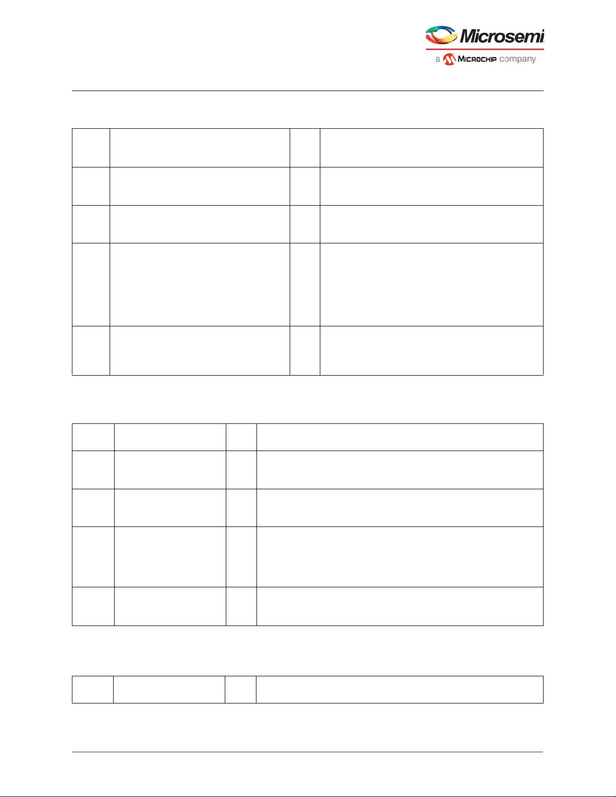
MDDR Subsystem
Table 56 • DDRC_ADDR_MAP_COL_3_CR (continued)
Bit
Numbe
rName
4 REG_DDRC_DIS_ACT_BYPASS 0×0 Only present in designs supporting activate bypass.
3 REG_DDRC_DIS_RD_BYPASS 0×0 Only present in designs supporting read bypass.
2 REG_DDRC_DIS_PRE_BYPASS 0×0 Only present in designs supporting precharge bypass.
1 REG_DDRC_DIS_COLLISION_PAGE_OPT0×0 When this is set to ‘0’, auto-precharge is disabled for
0 Reserved 0×0 Software should not rely on the value of a reserved bit.
Reset
Value Description
When 1, disable bypass path for high priority read
activates
When 1, disable bypass path for high priority read page
hits.
When 1, disable bypass path for high priority
precharges
the flushed command in a collision case. Collision
cases are write followed by read to same address, read
followed by write to same address, or write followed by
write to same address with REG_DDRC_DIS_WC bit =
1 (where same address comparisons exclude the two
address bits representing the critical word).
To provide compatibility with future products, the value
of a reserved bit should be preserved across a readmodify-write operation.
Table 57 • DDRC_MODE_REG_RD_WR_CR
Bit
Number Name
[31:4] Reserved 0×0 Software should not rely on the value of a reserved bit. To provide
3 REG_DDRC_MR_WR 0×0 When 1 is written and DDRC_REG_MR_WR_BUSY is Low, a mode
[2:1] REG_DDRC_MR_ADDR 0×0 Address of the Mode register that is to be written to.
0 REG_DDRC_MR_TYPE 0×0 Indicates whether the Mode register operation is read or write.
Table 58 • DDRC_MODE_REG_DATA_CR
Bit
Number Name
Reset
Value Description
compatibility with future products, the value of a reserved bit should be
preserved across a read-modify-write operation.
register read or write operation is started. There is no need for the CPU
to set this back to zero. This bit always reads as zero.
00: MR0
01: MR1
10: MR2
11: MR3
1: Read
0: Write
Reset
Value Description
Microsemi Proprietary UG0446 User Guide Revision 7.0 81
Page 93

MDDR Subsystem
Table 58 • DDRC_MODE_REG_DATA_CR
[31:16] Reserved 0×0 Software should not rely on the value of a reserved bit. To provide
compatibility with future products, the value of a reserved bit should be
preserved across a read-modify-write operation.
[15:0] REG_DDRC_MR_DATA 0×0 Mode register write data
Table 59 • DDRC_PWR_SAVE_1_CR
Bit
Number Name
Reset
Value Description
[31:13] Reserved 0×0 Software should not rely on the value of a
reserved bit. To provide compatibility with future
products, the value of a reserved bit should be
preserved across a read-modify-write
operation.
[12:6] REG_DDRC_POST_SELFREF_GAP_X32 0×10 Minimum time to wait after coming out of self
refresh before doing anything. This must be
larger than all the constraints that exist
(Specifications: maximum of t
and t
, which is 512 clocks).
XSDLL
XSNR
and t
XSRD
Unit: Multiples of 32 clocks.
[5:1] REG_DDRC_POWERDOWN_TO_X32 0×06 After this many clocks of NOP or DESELECT,
the controller puts the DRAM into power-down.
This must be enabled in the Master Control
register.
Unit: Multiples of 32 clocks.
0 REG_DDRC_CLOCK_STOP_EN 0×0 1: Stops the clock to the PHY whenever a clock
is not required by LPDDR1.
0: Clock will never be stopped.
This is only present for implementations
supporting mobile/LPDDR1 devices.
Table 60 • DDRC_PWR_SAVE_2_CR
Bit
Number Name
Reset
Value Description
[31:12] Reserved 0×0 Software should not rely on the value of a
reserved bit. To provide compatibility with future
products, the value of a reserved bit should be
preserved across a read-modify-write operation.
11 REG_DDRC_DIS_PAD_PD 0×0 1: Disable the pad power-down feature.
0: Enable the pad power-down feature.
Used only in non-DFI designs.
[10:3] REG_DDRC_DEEPPOWERDOWN_TO_X1024 0×0 Not supported.
[2:0] REG_DDRC_PAD_PD 0×0 If pads have a power-saving mode, this is the
greater of the time for the pads to enter power-
down or the time for the pads to exit power-
down. Used only in non-DFI designs. Unit:
clocks.
Microsemi Proprietary UG0446 User Guide Revision 7.0 82
Page 94

MDDR Subsystem
Table 61 • DDRC_ZQ_LONG_TIME_CR
Bit
Number Name
[31:10] Reserved 0×0 Software should not rely on the value of a reserved bit. To
[9:0] REG_DDRC_T_ZQ_LONG_NOP 0×0 Number of cycles of NOP required after a ZQCL (ZQ
Table 62 • DDRC_ZQ_SHORT_TIME_CR
Bit
Number Name
[31:10] Reserved 0×0 Software should not rely on the value of a reserved bit. To
[9:0] REG_DDRC_T_ZQ_SHORT_NOP 0×0 Number of cycles of NOP required after a ZQCS (ZQ
Reset
Value Description
provide compatibility with future products, the value of a
reserved bit should be preserved across a read-modify-write
operation.
calibration long) command is issued to DRAM. Units: Clock
cycles.
This is only present for implementations supporting DDR3
devices
Reset
Value Description
provide compatibility with future products, the value of a
reserved bit should be preserved across a read-modify-write
operation.
calibration short) command is issued to DRAM. Units: Clock
cycles.
This is only present for implementations supporting DDR3
devices.
Table 63 • DDRC_ZQ_SHORT_INT_REFRESH_MARGIN_1_CR
Bit
Number Name
[31:16] Reserved 0×0 Software should not rely on the value of a
[15:4] REG_DDRC_T_ZQ_SHORT_INTERVAL_X1024 0×0 20 bits are split into two registers.
Reset
Value Description
reserved bit. To provide compatibility with
future products, the value of a reserved bit
should be preserved across a read-modifywrite operation.
[11:0] bits of
REG_DDRC_T_ZQ_SHORT_INTERVAL_
X1024.
Average interval to wait between automatically
issuing ZQ calibration short (ZQCS)
commands to DDR3 devices. Not considered if
REG_DDRC_DIS_AUTO_ZQ = 1. Units: 1,024
clock cycles
This is only present for implementations
supporting DDR3 devices.
Microsemi Proprietary UG0446 User Guide Revision 7.0 83
Page 95
MDDR Subsystem
Table 63 • DDRC_ZQ_SHORT_INT_REFRESH_MARGIN_1_CR (continued)
[3:0] REG_DDRC_REFRESH_MARGIN 0×02 Threshold value in number of clock cycles
before the critical refresh or page timer expires.
A critical refresh is to be issued before this
threshold is reached. Microsemi recommends
using the default value.
Unit: Multiples of 32 clocks.
Table 64 • DDRC_ZQ_SHORT_INT_REFRESH_MARGIN_2_CR
Bit
Number Name
[31:8] Reserved 0×0 Software should not rely on the value of a
[7:0] REG_DDRC_T_ZQ_SHORT_INTERVAL_X1024 0×0 20 bits are split into two registers.
Table 65 • DDRC_PERF_PARAM_1_CR
Rese
t
Bit
Number Name
[31:16] Reserved 0×0 Software should not rely on the value of a reserved bit. To
Valu
e Description
provide compatibility with future products, the value of a
reserved bit should be preserved across a read-modify-write
operation.
Reset
Value Description
reserved bit. To provide compatibility with
future products, the value of a reserved bit
should be preserved across a read-modifywrite operation.
[19:12] bits of
REG_DDRC_T_ZQ_SHORT_INTERVAL_X10
24.
Average interval to wait between automatically
issuing ZQ calibration short (ZQCS)
commands to DDR3 devices. Not considered if
REG_DDRC_DIS_AUTO_ZQ = 1.
Units: 1,024 clock cycles
This is only present for implementations
supporting DDR3 devices.
Microsemi Proprietary UG0446 User Guide Revision 7.0 84
Page 96

MDDR Subsystem
Table 65 • DDRC_PERF_PARAM_1_CR (continued)
Rese
t
Bit
Number Name
[15:13] REG_DDRC_BURST_RDWR 0×0 001: Burst length of 4
12 Reserved 0×0 This bit must always be set to zero.
[11:5] REG_DDRC_RDWR_IDLE_GAP 0×04 When the preferred transaction store is empty for this many
4 REG_DDRC_PAGECLOSE 0×0 1: Bank is closed and kept closed if no transactions are
3 Reserved This bit must always be set to zero.
[2:0] REG_DDRC_LPR_NUM_ENTRIES 0×03 Number of entries in the low priority transaction store is this
Valu
e Description
010: Burst length of 8
100: Burst length of 16
All other values are reserved.
This controls the burst size used to access the DRAM. This
must match the BL mode register setting in the DRAM.
The DDRC and AXI controllers are optimized for a burst length
of 8.
The recommended setting is 8. A burst length of 16 is only
supported for LPDDR1. Setting to 16 when using LPDDR1 in
half/quarter bus mode may boost performance.
For systems that tend to do many single cycle random
transactions, a burst length of 4 may slightly improve system
performance.
clock cycles, switch to the alternate transaction store if it is
non-empty.
The read transaction store (both high and low priority) is the
default preferred transaction store and the write transaction
store is the alternate store.
When “Prefer write over read” is set, this is reversed.
available for it. This is different from auto-precharge:
(a) Explicit precharge commands are used, and not read/write
with auto-precharge and
(b) Page is not closed after a read/write if there is another
read/write pending to the same page.
0: Bank remains open until there is a need to close it (to open a
different page, or for page timeout or refresh timeout).
value plus 1.
READ_CAM_DEPTH – (REG_DDRC_LPR_NUM_ENTRIES +
1) is the number of entries available for the high priority
transaction store.
READ_CAM_DEPTH = Depth of the read transaction store,
that is, 8. Setting this to maximum value allocates all entries to
low priority transaction store.
Setting this to 0 allocates 1 entry to low priority transaction
store and the rest to high priority transaction store.
Note: In designs with ECC, number of lpr and wr
credits issued to the core is 1 less than the nonECC case. 1 entry each is reserved in wr and lpr
cam for storing the RMW requests arising out of
Single bit Error Correction RMW operation.
Microsemi Proprietary UG0446 User Guide Revision 7.0 85
Page 97

MDDR Subsystem
Table 66 • DDRC_HPR_QUEUE_PARAM_1_CR
Bit
Number Name
[31:16] Reserved 0×0 Software should not rely on the value of a reserved
15 REG_DDRC_HPR_MAX_STARVE_X32 0×0 Lower 1 bit of
[14:4] REG_DDRC_HPR_MIN_NON_CRITICAL 0×0 Number of clocks that the HPR queue is guaranteed
[3:0] REG_DDRC_HPR_XACT_RUN_LENGTH 0×0 Number of transactions that are serviced once the
Table 67 • DDRC_HPR_QUEUE_PARAM_2_CR
Bit
Number Name
[31:11] Reserved 0×0 Software should not rely on the value of a
[10:0] REG_DDRC_HPR_MAX_STARVE_X32 0×0 [11:1] bits of
Reset
Value Description
bit. To provide compatibility with future products, the
value of a reserved bit should be preserved across a
read-modify-write operation.
REG_DDRC_HPR_MAX_STARVE_X32.
Number of clocks that the HPR queue can be starved
before it goes critical. Unit: 32 clocks.
to be non-critical. Unit: 32 clocks.
HPR queue goes critical is the smaller of this value
and number of transactions available.
Units: Transactions.
Reset
Value Description
reserved bit. To provide compatibility with future
products, the value of a reserved bit should be
preserved across a read-modify-write operation.
REG_DDRC_HPR_MAX_STARVE_X32
Number of clocks that the HPR queue can be
starved before it goes critical. Unit: 32 clocks.
Table 68 • DDRC_LPR_QUEUE_PARAM_1_CR
Bit
Number Name
[31:16] Reserved 0×0 Software should not rely on the value of a
15 REG_DDRC_LPR_MAX_STARVE_X32 0×0 12 bits are split into two registers.
[14:4] REG_DDRC_LPR_MIN_NON_CRITICAL 0×0 Number of clocks that the LPR queue is
Microsemi Proprietary UG0446 User Guide Revision 7.0 86
Reset
Value Description
reserved bit. To provide compatibility with future
products, the value of a reserved bit should be
preserved across a read-modify-write operation.
Lower 1 bit of
REG_DDRC_LPR_MAX_STARVE_X32.
Number of clocks that the LPR queue can be
starved before it goes critical. Unit: 32 clocks.
guaranteed to be non-critical. Unit: 32 clocks.
Page 98

MDDR Subsystem
Table 68 • DDRC_LPR_QUEUE_PARAM_1_CR (continued)
Bit
Number Name
[3:0] REG_DDRC_LPR_XACT_RUN_LENGTH 0×0 Number of transactions that are serviced once
Table 69 • DDRC_LPR_QUEUE_PARAM_2_CR
Bit
Number Name
[31:16] Reserved 0×0 Software should not rely on the value of a
[10:0] REG_DDRC_LPR_MAX_STARVE_X32 0×0 12 bits are split into two registers.
Table 70 • DDRC_WR_QUEUE_PARAM_CR
Reset
Value Description
the LPR queue goes critical is the smaller of this
value and number of transactions available.
Units: Transactions.
Reset
Value Description
reserved bit. To provide compatibility with future
products, the value of a reserved bit should be
preserved across a read-modify-write operation.
[11:1] bits of
REG_DDRC_HPR_MAX_STARVE_X32.
Number of clocks that the LPR queue can be
starved before it goes critical. Unit: 32 clocks.
Bit
Number Name
[31:15] Reserved 0×0 Software should not rely on the value of a
[14:4] REG_DDRC_W_MIN_NON_CRITICAL 0×0 Number of clocks that the write queue is
[3:0] REG_DDRC_W_XACT_RUN_LENGTH 0×0 Number of transactions that are serviced once
Table 71 • DDRC_PERF_PARAM_2_CR
Bit
Number Name
[31:12] Reserved 0×0 Software should not rely on the value of a
11 REG_DDRC_BURSTCHOP 0×0 Not supported in this version of the DDRC
Reset
Value Description
reserved bit. To provide compatibility with future
products, the value of a reserved bit should be
preserved across a read-modify-write operation.
guaranteed to be non-critical. Unit: 32 clocks.
the WR queue goes critical is the smaller of this
value and number of transactions available.
Units: Transactions.
Reset
Value Description
reserved bit. To provide compatibility with future
products, the value of a reserved bit should be
preserved across a read-modify-write operation.
controller always reads as zero.
Microsemi Proprietary UG0446 User Guide Revision 7.0 87
Page 99

MDDR Subsystem
Table 71 • DDRC_PERF_PARAM_2_CR
10 REG_DDRC_BURST_MODE 0×0 1: Interleaved burst mode
0: Sequential burst mode
The burst mode programmed in the DRAM mode
register and the order of the input data to the
controller should both match the value
programmed in the
REG_DDRC_BURST_MODE register.
[9:2] REG_DDRC_GO2CRITICAL_HYSTERESIS 0×0 Indicates the number of cycles that
CO_GS_GO2CRITICAL_RD or
CO_GS_GO2CRITICAL_WR must be asserted
before the corresponding queue moves to the
critical state in the DDRC.
1 REG_DDRC_PREFER_WRITE 0×0 If set, the bank selector prefers writes over
reads.
0 REG_DDRC_FORCE_LOW_PRI_N 0×0 Active Low signal. When asserted (‘0’), all
incoming transactions are forced to low priority.
Forcing the incoming transactions to low priority
implicitly turns off bypass.
Table 72 • DDRC_PERF_PARAM_3_CR
Bit
Number Name
[31:1] Reserved 0×0 Software should not rely on the value of a
0 REG_DDRC_EN_2T_TIMING_MODE 0×0 1: DDRC uses 2T timing.
Table 73 • DDRC_DFI_RDDATA_EN_CR
Bit
Number Name
[31:5] Reserved 0×0 Software should not rely on the value of a
[4:0] REG_DDRC_DFI_T_RDDATA_EN 0×0 Time from the assertion of a READ command on
Reset
Value Description
reserved bit. To provide compatibility with future
products, the value of a reserved bit should be
preserved across a read-modify-write operation.
0: DDRC uses 1T timing.
Reset
Value Description
reserved bit. To provide compatibility with future
products, the value of a reserved bit should be
preserved across a read-modify-write operation.
the DFI interface to the assertion of the
DDRC_DFI_RDDATA_EN signal.
Program this to (RL – 1), where RL is the read
latency of the DRAM.
For LPDDR1 this should be set to RL. Units:
Clocks
Microsemi Proprietary UG0446 User Guide Revision 7.0 88
Page 100

MDDR Subsystem
Table 74 • DDRC_DFI_MIN_CTRLUPD_TIMING_CR
Bit
Number Name
[31:10] Reserved 0×0 Software should not rely on the value of a
[9:0] REG_DDRC_DFI_T_CTRLUP_MIN 0×03 Specifies the minimum number of clock cycles
Table 75 • DDRC_DFI_MAX_CTRLUPD_TIMING_CR
Bit
Number Name
[31:10] Reserved 0×0 Software should not rely on the value of a
[9:0] REG_DDRC_DFI_T_CTRLUP_MAX 0×40 Specifies the maximum number of clock cycles
Reset
Value Description
reserved bit. To provide compatibility with future
products, the value of a reserved bit should be
preserved across a read-modify-write operation.
that the DDRC_DFI_CTRLUPD_REQ signal
must be asserted. Lowest value to assign to this
variable is 0x3. Units: Clocks
Reset
Value Description
reserved bit. To provide compatibility with future
products, the value of a reserved bit should be
preserved across a read-modify-write operation.
that the DDRC_DFI_CTRLUPD_REQ signal can
assert. Lowest value to assign to this variable is
0x40. Units: Clocks
Table 76 • DDRC_DYN_SOFT_RESET_ALIAS_CR
Bit
Number Name
[31:3] Reserved 0×0 Software should not rely on the value
2 AXIRESET 0×1 Set when main AXI reset signal is
Microsemi Proprietary UG0446 User Guide Revision 7.0 89
Reset
Value Description
of a reserved bit. To provide
compatibility with future products, the
value of a reserved bit should be
preserved across a read-modify-write
operation.
asserted. Reads and writes to the
dynamic registers should not be
carried out. This is a read only bit.
 Loading...