

Page 1
MGC3130
Hillstar Development Kit
User’s Guide
2013 Microchip Technology Inc. DS40001721A
Page 2

Note the following details of the code protection feature on Microchip devices:
YSTEM
CERTIFIED BY DNV
== ISO/TS 16949 ==
• Microchip products meet the specification contained in their particular Microchip Data Sheet.
• Microchip believes that its family of products is one of the most secure families of its kind on the market today, when used in the
intended manner and under normal conditions.
• There are dishonest and possibly illegal methods used to breach the code protection feature. All of these methods, to our
knowledge, require using the Microchip products in a manner outside the operating specifications contained in Microchip’s Data
Sheets. Most likely, the person doing so is engaged in theft of intellectual property.
• Microchip is willing to work with the customer who is concerned about the integrity of their code.
• Neither Microchip nor any other semiconductor manufacturer can guarantee the security of their code. Code protection does not
mean that we are guaranteeing the product as “unbreakable.”
Code protection is constantly evolving. We at Microchip are committed to continuously improving the code protection features of our
products. Attempts to break Microchip’s code protection feature may be a violation of the Digital Millennium Copyright Act. If such acts
allow unauthorized access to your software or other copyrighted work, you may have a right to sue for relief under that Act.
Information contained in this publication regarding device
applications and the like is provided only for your convenience
and may be superseded by updates. It is your responsibility to
ensure that your application meets with your specifications.
MICROCHIP MAKES NO REPRESENTATIONS OR
WARRANTIES OF ANY KIND WHETHER EXPRESS OR
IMPLIED, WRITTEN OR ORAL, STATUTORY OR
OTHERWISE, RELATED TO THE INFORMATION,
INCLUDING BUT NOT LIMITED TO ITS CONDITION,
QUALITY, PERFORMANCE, MERCHANTABILITY OR
FITNESS FOR PURPOSE. Microchip disclaims all liability
arising from this information and its use. Use of Microchip
devices in life support and/or safety applications is entirely at
the buyer’s risk, and the buyer agrees to defend, indemnify and
hold harmless Microchip from any and all damages, claims,
suits, or expenses resulting from such use. No licenses are
conveyed, implicitly or otherwise, under any Microchip
intellectual property rights.
Trademarks
The Microchip name and logo, the Microchip logo, dsPIC,
FlashFlex, K
PICSTART, PIC
and UNI/O are registered trademarks of Microchip Technology
Incorporated in the U.S.A. and other countries.
FilterLab, Hampshire, HI-TECH C, Linear Active Thermistor,
MTP, SEEVAL and The Embedded Control Solutions
Company are registered trademarks of Microchip Technology
Incorporated in the U.S.A.
Silicon Storage Technology is a registered trademark of
Microchip Technology Inc. in other countries.
Analog-for-the-Digital Age, Application Maestro, BodyCom,
chipKIT, chipKIT logo, CodeGuard, dsPICDEM,
dsPICDEM.net, dsPICworks, dsSPEAK, ECAN,
ECONOMONITOR, FanSense, HI-TIDE, In-Circuit Serial
Programming, ICSP, Mindi, MiWi, MPASM, MPF, MPLAB
Certified logo, MPLIB, MPLINK, mTouch, Omniscient Code
Generation, PICC, PICC-18, PICDEM, PICDEM.net, PICkit,
PICtail, REAL ICE, rfLAB, Select Mode, SQI, Serial Quad I/O,
Total Endurance, TSHARC, UniWinDriver, WiperLock, ZENA
and Z-Scale are trademarks of Microchip Technology
Incorporated in the U.S.A. and other countries.
SQTP is a service mark of Microchip Technology Incorporated
in the U.S.A.
GestIC and ULPP are registered trademarks of Microchip
Technology Germany II GmbH & Co. KG, a subsidiary of
Microchip Technology Inc., in other countries.
All other trademarks mentioned herein are property of their
respective companies.
© 2013, Microchip Technology Incorporated, Printed in the
U.S.A., All Rights Reserved.
Printed on recycled paper.
ISBN: 9781620775134
EELOQ, KEELOQ logo, MPLAB, PIC, PICmicro,
32
logo, rfPIC, SST, SST Logo, SuperFlash
QUALITY MANAGEMENT S
DS40001721A-page 2 2013 Microchip Technology Inc.
Microchip received ISO/TS-16949:2009 certification for its worldwide
headquarters, design and wafer fabrication facilities in Chandler and
Tempe, Arizona; Gresham, Oregon and design centers in California
and India. The Company’s quality system processes and procedures
are for its PIC
devices, Serial EEPROMs, microperipherals, nonvolatile memory and
analog products. In addition, Microchip’s quality system for the design
and manufacture of development systems is ISO 9001:2000 certified.
®
MCUs and dsPIC® DSCs, KEELOQ
®
code hopping
Page 3

Object of Declaration: MGC3130 Hillstar Development Kit User’s Guide
2013 Microchip Technology Inc. DS40001721A-page 3
Page 4

MGC3130 Hillstar Development Kit User’s Guide
NOTES:
DS40001721A-page 4 2013 Microchip Technology Inc.
Page 5

MGC3130 HILLSTAR DEVELOPMENT KIT
USER’S GUIDE
Table of Contents
Preface ........................................................................................................................... 7
Introduction............................................................................................................ 7
Document Layout .................................................................................................. 7
Conventions Used in this Guide ............................................................................ 8
Warranty Registration............................................................................................ 9
Recommended Reading........................................................................................ 9
The Microchip Web Site ...................................................................................... 10
Development Systems Customer Change Notification Service .......................... 10
Customer Support ............................................................................................... 11
Revision History .................................................................................................. 11
Chapter 1. Overview
1.1 Introduction ................................................................................................... 13
1.2 Hillstar Concept and Deliverables ................................................................ 13
1.3 Hillstar Development Kit Package Content .................................................. 14
1.4 Hillstar Development Kit Reference Electrodes ........................................... 15
1.5 MGC3130 Software Package – Aurea GUI and GestIC Library ................... 17
1.6 MGC3130 Software Development Kit (SDK) ................................................ 17
Chapter 2. Getting Started
2.1 Prerequisites ................................................................................................ 19
2.2 Step 1: Build-up Development Kit ................................................................ 19
2.3 Step 2: Connecting Hillstar Development Kit with Your PC ......................... 20
2.4 Step 3: Install Windows CDC Driver ............................................................. 20
2.5 Step 4: Start Aurea ....................................................................................... 20
Chapter 3. Hillstar Boards – Hardware Description
3.1 Overview ...................................................................................................... 23
3.1.1 I2C™ to USB Bridge .................................................................................. 23
3.1.2 MGC3130 Unit ........................................................................................... 23
3.1.3 95x60 mm Reference Electrode PCB ........................................................ 23
3.2 MGC3130 Unit ............................................................................................. 24
3.3 Hillstar 95x60 mm Reference Electrode ...................................................... 25
2
3.4 I
C to USB Bridge ....................................................................................... 27
Chapter 4. Design In: Hillstar In Target Application
4.1 Introduction ................................................................................................... 29
4.2 Integration Examples .................................................................................... 29
Chapter 5. Troubleshooting
2013 Microchip Technology Inc. DS40001721A-page 5
Page 6

MGC3130 Hillstar Development Kit User’s Guide
Appendix A. Schematics
A.1 Introduction .................................................................................................. 35
A.2 Bill of Materials ............................................................................................. 35
A.3 Board – Schematics and Layout .................................................................. 37
Appendix B. Sensitivity Profile and Capacitances
B.1 Introduction .................................................................................................. 41
B.2 Sensitivity Profiles ........................................................................................ 41
B.3 Electrode Capacities .................................................................................... 42
Appendix C. Parameterization Support
C.1 How to Build a Hand Brick ........................................................................... 43
C.2 Usage of the Hand Brick as Artificial Hand .................................................. 45
Appendix D. Driver Installation Manual
D.1 Open Device Manager ................................................................................. 47
D.2 Select Device ............................................................................................... 47
D.3 Locate Driver ............................................................................................... 48
D.4 Verify Communication .................................................................................. 48
Appendix E. Glossary
Worldwide Sales and Service .....................................................................................50
DS40001721A-page 6 2013 Microchip Technology Inc.
Page 7
MGC3130 HILLSTAR DEVELOPMENT
KIT USER’S GUIDE
Preface
NOTICE TO CUSTOMERS
All documentation becomes dated, and this manual is no exception. Microchip tools and
documentation are constantly evolving to meet customer needs, so some actual dialogs
and/or tool descriptions may differ from those in this document. Please refer to our web site
(www.microchip.com) to obtain the latest documentation available.
Documents are identified with a “DS” number. This number is located on the bottom of each
page, in front of the page number. The numbering convention for the DS number is
“DSXXXXXA”, where “XXXXX” is the document number and “A” is the revision level of the
document.
For the most up-to-date information on development tools, see the MPLAB
Select the Help menu, and then Topics to open a list of available online help files.
INTRODUCTION
®
IDE online help.
This chapter contains general information that will be useful to know before using the
Hillstar Development Kit. Items discussed in this chapter include:
• Document Layout
• Conventions Used in this Guide
• Warranty Registration
• Recommended Reading
• The Microchip Web Site
• Development Systems Customer Change Notification Service
• Customer Support
• Revision History
DOCUMENT LAYOUT
This document describes the installation and use of the MGC3130 Hillstar
Development Kit. The document is organized as follows:
• Chapter 1. “Overview”
• Chapter 2. “Getting Started”
• Chapter 3. “Hillstar Boards – Hardware Description”
• Chapter 4. “Design In: Hillstar In Target Application”
• Chapter 5. “Troubleshooting”
• Appendix A. “Schematics”
• Appendix B. “Sensitivity Profile and Capacitances”
• Appendix C. “Parameterization Support”
• Appendix D. “Driver Installation Manual”
• Appendix E. “Glossary”
2013 Microchip Technology Inc. DS40001721A-page 7
Page 8

MGC3130 Hillstar Development Kit User’s Guide
CONVENTIONS USED IN THIS GUIDE
This manual uses the following documentation conventions:
DOCUMENTATION CONVENTIONS
Description Represents Examples
Arial font:
Italic characters Referenced books MPLAB
Emphasized text ...is the only compiler...
Initial caps A window the Output window
A dialog the Settings dialog
A menu selection select Enable Programmer
Quotes A field name in a window or
dialog
Underlined, italic text with
right angle bracket
Bold characters A dialog button Click OK
N‘Rnnnn A number in verilog format,
Text in angle brackets < > A key on the keyboard Press <Enter>, <F1>
Courier New font:
Plain Courier New Sample source code #define START
Italic Courier New A variable argument file.o, where file can be
Square brackets [ ] Optional arguments mcc18 [options] file
Curly brackets and pipe
character: { | }
Ellipses... Replaces repeated text var_name [,
A menu path File>Save
A tab Click the Power tab
where N is the total number of
digits, R is the radix and n is a
digit.
Filenames autoexec.bat
File paths c:\mcc18\h
Keywords _asm, _endasm, static
Command-line options -Opa+, -Opa-
Bit values 0, 1
Constants 0xFF, ‘A’
Choice of mutually exclusive
arguments; an OR selection
Represents code supplied by
user
“Save project before build”
4‘b0010, 2‘hF1
any valid filename
[options]
errorlevel {0|1}
var_name...]
void main (void)
{ ...
}
®
IDE User’s Guide
DS40001721A-page 8 2013 Microchip Technology Inc.
Page 9

WARRANTY REGISTRATION
Please complete the enclosed Warranty Registration Card and mail it promptly.
Sending in the Warranty Registration Card entitles users to receive new product
updates. Interim software releases are available at the Microchip web site.
RECOMMENDED READING
This user's guide describes how to use the Hillstar Development Kit. Other useful
documents are listed below. The following Microchip documents are available and
recommended as supplemental reference resources.
•“MGC3130 GestIC
(DS40001716). This document describes the MGC3130 system characteristic
parameters and the design process. It enables the user to generate a good
electrode design and to parameterize the full GestIC system.
• “MGC3130 GestIC
This document is the interface description of the MGC3130’s GestIC Library. It
outlines the function of the Library’s message interface, and contains the
complete message reference to control and operate the MGC3130 system.
• “MGC3130 Single-Zone 3D Gesture Controller Data Sheet” (DS40001667).
Consult this document for information regarding the MGC3130 3D Tracking and
Gesture Controller.
• “MGC3130 Aurea Graphical User Interface User’s Guide” (DS40001681). This
document describes how to use the MGC3130 Aurea Graphical User Interface.
Preface
®
Design Guide: Electrodes and System Design
®
Library Interface Description User’s Guide” (DS40001718).
2013 Microchip Technology Inc. DS40001721A-page 9
Page 10

MGC3130 Hillstar Development Kit User’s Guide
THE MICROCHIP WEB SITE
Microchip provides online support via our web site at www.microchip.com. This web
site is used as a means to make files and information easily available to customers.
Accessible by using your favorite Internet browser, the web site contains the following
information:
• Product Support – Data sheets and errata, application notes and sample
programs, design resources, user’s guides and hardware support documents,
latest software releases and archived software
• General Technical Support – Frequently Asked Questions (FAQs), technical
support requests, online discussion groups, Microchip consultant program
member listing
• Business of Microchip – Product selector and ordering guides, latest Microchip
press releases, listing of seminars and events, listings of Microchip sales offices,
distributors and factory representatives
DEVELOPMENT SYSTEMS CUSTOMER CHANGE NOTIFICATION SERVICE
Microchip’s customer notification service helps keep customers current on Microchip
products. Subscribers will receive e-mail notification whenever there are changes,
updates, revisions or errata related to a specified product family or development tool of
interest.
To register, access the Microchip web site at www.microchip.com, click on Customer
Change Notification and follow the registration instructions.
The Development Systems product group categories are:
• Compilers – The latest information on Microchip C compilers, assemblers, linkers
and other language tools. These include all MPLAB
assemblers (including MPASM™ assembler); all MPLAB linkers (including
MPLINK™ object linker); and all MPLAB librarians (including MPLIB™ object
librarian).
• Emulators – The latest information on Microchip in-circuit emulators.This
includes the MPLAB REAL ICE™ and MPLAB ICE 2000 in-circuit emulators.
• In-Circuit Debuggers – The latest information on the Microchip in-circuit
debuggers. This includes MPLAB ICD 3 in-circuit debuggers and PICkit™ 3
debug express.
• MPLAB
Integrated Development Environment for development systems tools. This list is
focused on the MPLAB IDE, MPLAB IDE Project Manager, MPLAB Editor and
MPLAB SIM simulator, as well as general editing and debugging features.
• Programmers – The latest information on Microchip programmers. These include
production programmers such as MPLAB REAL ICE in-circuit emulator, MPLAB
ICD 3 in-circuit debugger and MPLAB PM3 device programmers. Also included
are nonproduction development programmers such as PICSTART
PICkit 2 and 3.
®
IDE – The latest information on Microchip MPLAB IDE, the Windows®
®
C compilers; all MPLAB
®
Plus and
DS40001721A-page 10 2013 Microchip Technology Inc.
Page 11

CUSTOMER SUPPORT
Users of Microchip products can receive assistance through several channels:
• Distributor or Representative
• Local Sales Office
• Field Application Engineer (FAE)
• Technical Support
Customers should contact their distributor, representative or field application engineer
(FAE) for support. Local sales offices are also available to help customers. A listing of
sales offices and locations is included in the back of this document.
Technical support is available through the web site at:
http://www.microchip.com/support.
REVISION HISTORY
Revision A (October, 2013)
This is the initial release of this document.
Preface
2013 Microchip Technology Inc. DS40001721A-page 11
Page 12

MGC3130 Hillstar Development Kit User’s Guide
NOTES:
DS40001721A-page 12 2013 Microchip Technology Inc.
Page 13

MGC3130 HILLSTAR DEVELOPMENT
Chapter 1. Overview
1.1 INTRODUCTION
The MGC3130 is the first product based on Microchip’s GestIC® technology. It is
developed as a mixed-signal controller. The MGC3130 has one transmit and five very
sensitive receive channels that are capable to detect changes of a transmitted electrical
field (E-field) corresponding to capacitive changes in the femtofarad (1 fF = 10
range.
In order to transmit and receive an electrical field, electrodes have to be connected to
the transmitting and receiving channels of the MGC3130 controller. The spatial
arrangement of the electrodes allows the chip to determine the center of gravity of the
electric field distortion, and thus position tracking and gesture recognition of a user’s
hand in the detection space.
1.2 HILLSTAR CONCEPT AND DELIVERABLES
The Hillstar Development Kit is designed to support an easy integration of Microchip’s
MGC3130 3D Tracking and Gesture Controller into customer’s applications. It provides
MGC3130 system setup, related hardware and software references.
With the MGC3130 Software Package, including Aurea Graphical User Interface and
GestIC Library, the MGC3130 Software Development Kit (SDK) and PIC18 Host
Reference code, design-in is easy in five steps:
1. Feature Definition
2. Electrode Design
3. MGC3130 Parameterization
4. Host Application Programming
5. Verification
Hillstar hardware builds a complete MGC3130 reference system consisting of three
individual PCBs:
• MGC3130 Unit
2
•I
C™ to USB Bridge
• Reference Electrode with a 95x60 mm sensitive area
It can be plugged to a PC via USB cable and used for evaluation of MGC3130 chip and
GestIC technology. During the customer’s design-in process the individual boards can
be combined according to the customers need.
Three examples are given below:
• Combine MGC3130 Unit and I
electrodes
•Use I
• Combine MGC3130 Unit and Electrodes to develop gesture-driven applications
2
C to USB Bridge to parameterize and debug the MGC3130 application
circuitry in the customer’s design
for PC based or embedded software environments
2
C to USB Bridge to evaluate customized
KIT USER’S GUIDE
-15
F)
2013 Microchip Technology Inc. DS40001721A-page 13
Page 14
MGC3130 Hillstar Development Kit User’s Guide
The Hillstar Development Kit provides an artificial test hand, further called hand brick,
helping to stimulate the human hand operating the GestIC application. The hand brick
has to be used during the design-in process to parametrize and evaluate customer’s
applications. The hand brick’s surface is conductive and connected to GND via cable
in order to reproduce the grounding conditions of the human body.
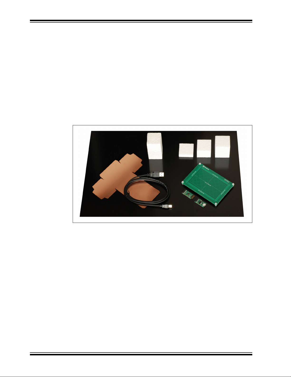
1.3 HILLSTAR DEVELOPMENT KIT PACKAGE CONTENT
The Hillstar Development Kit package content is listed below:
• MGC3130 Module
2C
•I
to USB Bridge Module
• 4-layer reference electrode (95x60 mm sensitive area)
• ‘Hand brick’ set (self-assembly, four foam blocks, one copper foil)
• USB Cable for PC connection
FIGURE 1-1: HILLSTAR DEVELOPMENT KIT
The ‘hand brick’ set is used during the design-in process for sensor calibration and
performance evaluation purposes. For usage and assembly information, refer to
Appendix C. “Parameterization Support”.
DS40001721A-page 14 2013 Microchip Technology Inc.
Page 15
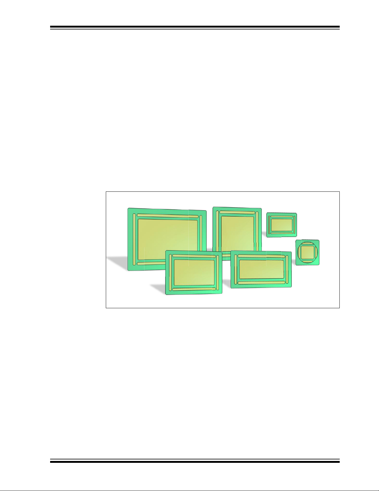
1.4 HILLSTAR DEVELOPMENT KIT REFERENCE ELECTRODES
140x90
100x50
95x60
80x80
50x30
30x30
The Hillstar development kit includes a collection of layout references (Gerber files) for
electrode designs and ready-to-use sensor modules with MGC3130 backside
assembly.
The following electrode designs are included:
• 140x90 mm sensitive area – outline 168 x 119 mm
• 95x60 mm sensitive area – outline of 120 x 85 mm
• 80x80 mm sensitive area – outline 104 x 104 mm
• 100x50 mm sensitive area – outline 128 x 72 mm
• 50x30 mm sensitive area – outline 63 x 47 mm
• 30x30 mm sensitive area – outline 49 x 49 mm
Sensor Modules
• 95x60 mm sensitive area – outline of 120 x 85 mm
• 30x30 mm sensitive area – outline 49 x 52 mm
Overview
FIGURE 1-2:
HILLSTAR DEVELOPMENT KIT REFERENCE
ELECTRODES
Dimensions of the designs are given in Table 1-1 and Figure 1-3 below.
2013 Microchip Technology Inc. DS40001721A-page 15
Page 16

MGC3130 Hillstar Development Kit User’s Guide
TABLE 1-1: ELECTRODE DIMENSIONS
Sensitive Area 140x90 mm 95x60 mm
Versi on 1.0 1.0 1.0 1.0 1.0 1.0
Layer 22 2222
Aspect Ratio approx. 3:2 approx. 3:2 1:1 approx. 2:1 5:3 1:1
A 168 mm 120 mm 104 mm 128 mm 63 mm 49 mm
B 119 mm 85 mm 104 mm 72 mm 47 mm 49 mm
C 138 mm 95,7 mm 79.8 mm 103,6 mm 50 mm 31.8 mm
D 88,7 mm 60,5 mm 79.8 mm 99,6 mm 46 mm 27,3 mm
E 131,7 mm 91,7 mm 75,8 mm 99,6 mm 46 mm 27,3 mm
F 5 mm 5 mm 5 mm 5 mm 2,5 mm 3,5 mm
G 128 mm 85,7 mm 69,8 mm 93,6 mm 44 mm 25,8 mm
H 78,7 mm 50, 5 mm 69, 8 mm 36, 8 mm 24 mm 25,8 mm
Center Electrode
cross-hatching
Tx Electrode
cross-hatching
-under center
electrode
-outside center
electrode
Note 1: These dimensions are also valid for 95x60 mm sensor module.
2: These dimensions are also valid for 30x30 mm sensor module except the B dimension which is equal to
52 and Tx electrode which is solid instead of cross-hatched.
3% 3% 5% 5% 5% 5%
50 %
20 %
50%
20%
(1)
80x80 mm 100x50 mm 50x30 mm 30x30 mm
50%
20%
50 %
20 %
50 %
20 %
50 %
20 %
(2)
DS40001721A-page 16 2013 Microchip Technology Inc.
Page 17

FIGURE 1-3: ELECTRODE DIMENSIONS
D
C
B
A
E
F
G
H
F
Tx
Rx
Overview
The Gerber data of all electrode reference designs are included in the MGC3130
Hillstar Hardware Reference package and can be downloaded from Microchip’s web
site www.microchip.com/GestICGettingStarted.
1.5 MGC3130 SOFTWARE PACKAGE – AUREA GUI AND GestIC LIBRARY
The MGC3130 Software Package contains all relevant system software and
documentation. Hillstar Development Kit is supported by MGC3130 Software Package
0.4 and following versions.
The package contains:
• Aurea PC software
• GestIC Library binary file
• GestIC Parameterization files
• Windows CDC driver
• Documentation
The latest MGC3130 software package can be downloaded from Microchip’s web site
www.microchip.com/GestICGettingStarted.
1.6 MGC3130 SOFTWARE DEVELOPMENT KIT (SDK)
The MGC3130 Software Development Kit (SDK) supports the integration of MGC3130
into a software environment. Thus, it includes a C reference code for GestIC API, a
precompiled library for Windows operating systems and a demo application using the
GestIC API interface.
Hillstar Development Kit is supported by MGC3130 SDK 0.4 and the following versions.
The latest SDK can be downloaded from Microchip’s web site
www.microchip.com/GestICGettingStarted.
2013 Microchip Technology Inc. DS40001721A-page 17
Page 18

MGC3130 Hillstar Development Kit User’s Guide
NOTES:
DS40001721A-page 18 2013 Microchip Technology Inc.
Page 19
Hillstar Development Kit can be used as a stand-alone GestIC system and evaluated
in conjunction with the Aurea PC software. This section describes how to get started.
2.1 PREREQUISITES
The following prerequisites have to be fulfilled:
• PC with Windows
and minimum screen resolution of 1024x768
• Hillstar Development Kit (MGC3130 Unit, I
electrode)
• MGC3130 Software Package 0.4 and following versions
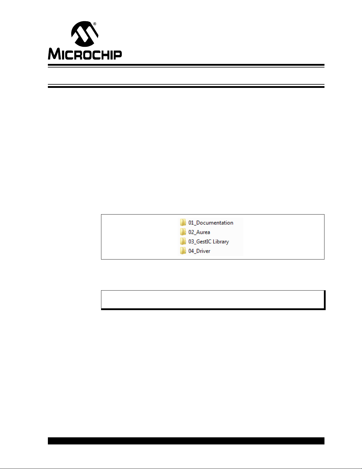
The MGC3130 Software Package is available as a .zip file. Unzip the file, run
setup.exe and install the package to your PC. The folder structure is as shown in
Figure 2-1.
FIGURE 2-1: FOLDER STRUCTURE
MGC3130 HILLSTAR DEVELOPMENT KIT
USER’S GUIDE
Chapter 2. Getting Started
®
XP, Windows 7 or Windows 8 operating system and USB port
2
C to USB Bridge, 95x60 mm frame
2.2 STEP 1: BUILD-UP DEVELOPMENT KIT
Connect Electrodes, MGC3130 Unit and I2C to USB Bridge as shown in Figure 2-2.
Note: Make sure the MGC3130 Unit and the I2C USB Bridge are already con-
nected before plugging in the USB connection.
2013 Microchip Technology Inc. DS40001721A-page 19
Page 20

MGC3130 Hillstar Development Kit User’s Guide
I2C™ to USB Bridge
FIGURE 2-2: HILLSTAR DEVELOPMENT KIT ASSEMBLING
2.3 STEP 2: CONNECTING HILLSTAR DEVELOPMENT KIT WITH YOUR PC
Use the supplied USB cable to connect the Hillstar Development Kit to your PC. The
Power LEDs on both, I
Furthermore, LED 1 on the I
1 is flashing slow (~1 Hz), the Windows CDC driver is already installed on your PC.
Please skip the next step and go to Section 2.5 “Step 4: Start Aurea”.
2
C to USB Bridge and MGC3130 Unit will illuminate.
2
C to USB Bridge will flash very fast (~10 Hz). In case LED
2.4 STEP 3: INSTALL WINDOWS CDC DRIVER
The Windows CDC driver can be found in the MGC3130 Software Package in folder
04_Driver.
When the Hillstar Development Kit is connected to your PC for the first time, Windows
requests the appropriate device driver and guides you through the installation process.
Alternatively, you can install the driver manually, (e.g., using the device manager). An
example for Windows 7 is given in Appendix D. “Driver Installation Manual”.
2.5 STEP 4: START AUREA
Aurea Graphical User Interface, shown in Figure 2-3, is included in the MGC3130
Software Package in the folder 02_Aurea.
Open Aurea.exe. Aurea detects the connected device automatically and is ready for
use.
DS40001721A-page 20 2013 Microchip Technology Inc.
Page 21

FIGURE 2-3: AUREA GRAPHICAL USER INTERFACE
Evaluate Colibri Suite Discover Signals Setup MGC3130
1. Positions Tracking
2. Gesture Recognition
3. Demo applications
1. View signals
2. Write log file
3. Advanced features
1. AFE parameterisation
2. Colibri Suite parameterization
3. Update GestIC Library
4. Measure Electrode capacitances
Getting Started
2013 Microchip Technology Inc. DS40001721A-page 21
Page 22

MGC3130 Hillstar Development Kit User’s Guide
NOTES:
DS40001721A-page 22 2013 Microchip Technology Inc.
Page 23

MGC3130 HILLSTAR DEVELOPMENT
1
3
9
68
2
4
5
7
10
11
13
12
I2C™ to USB Bridge
MGC3130 Unit Reference Electrode PCB
Chapter 3. Hillstar Boards – Hardware Description
3.1 OVERVIEW
The Hillstar key components are listed below and highlighted in Figure 3-1.
FIGURE 3-1: HILLSTAR DEVELOPMENT KIT OVERVIEW
KIT USER’S GUIDE
3.1.1 I2C™ to USB Bridge
1. PIC18F14K50 USB microcontroller
2. USB mini-B connector
3. MCP1801T LDO voltage regulator (converts 5V USB to 3.3 V board supply)
4. Status LEDs (power, communication status)
5. Data interface: 6-pin socket for data communication and power supply
3.1.2 MGC3130 Unit
6. MGC3130 3D Tracking and Gesture Controller
7. Data interface: 6-pin header for data communication and power supply
8. Status LED (power)
9. Interface select
10. Electrode interface: 7-pin socket
3.1.3 95x60 mm Reference Electrode PCB
11. Receive electrodes
12. Acrylic cover glass (120 x 85 x 2 mm)
13. Electrode interface: 7-pin header (mounted on backside)
2013 Microchip Technology Inc. DS40001721A-page 23
Page 24
MGC3130 Hillstar Development Kit User’s Guide
The Gerber data of all Hillstar Development Kit components are included in the
MGC3130 Hillstar Hardware Reference package and can be downloaded from
Microchip’s web site www.microchio.com/GestICGettingStarting.
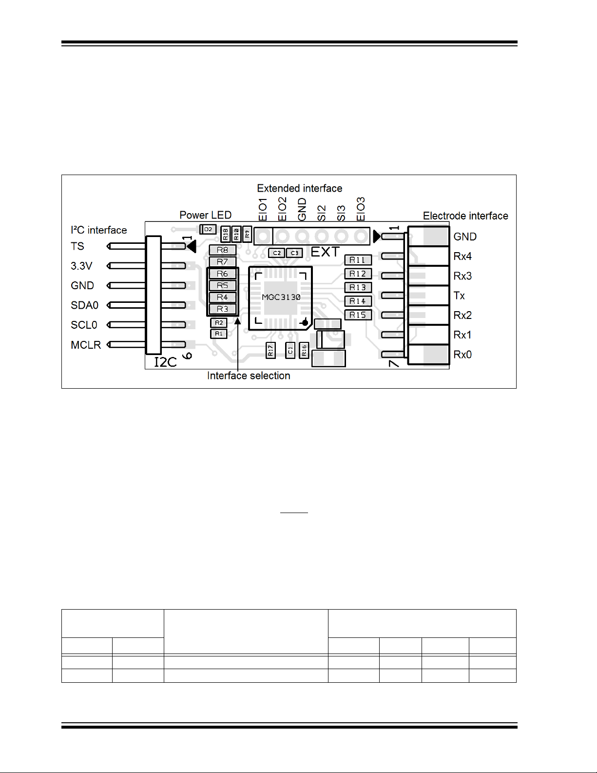
3.2 MGC3130 UNIT
The key element of the MGC3130 Unit is Microchip’s MGC3130 3D Tracking and
Gesture Controller. The layout print of the unit is shown in Figure 3-2.
FIGURE 3-2: MGC3130 UNIT
The unit provides a 2 mm 7-pin board-to-board connector (socket) to connect the
electrode. The interface includes the following signals: GND, Rx4, Rx3, Tx, Rx2, Rx1,
and Rx0. Alternatively, the board-to-board connector can be replaced by a 1 mm
Flexible Printed Circuitry (FPC) connector which is prepared as a design option. The
five Rx channels of the MGC3130 (Rx0…Rx4) are connected to the receive electrodes
via 10 k resistors in order to suppress irradiated high-frequency signals (R11, R12,
R13, R14, and R15). The MGC3130 signal generator is connected via the Tx signal to
the transmit electrode.
The data connection to the Hillstar I
2
C to USB Bridge is realized by a 6-pin 2 mm
board-to-board connector (header). The interface includes the following signals: EIO0,
3.3V, GND, SDA0, SCL0, and MCLR
. Alternatively, it is possible to use a 1 mm FPC
connector which can be assembled to the bottom side.
The MGC3130 unit acts as an I
2
C slave device. Table 3-1 shows the configuration of
the MGC3130 interface selection pins (IS1, IS2) which can be pulled to V
via resistors (R3, R4, R5, and R6) to select the I
2
C slave address. The I2C device
address 0x42 is set as default.
TABLE 3-1: MGC3130 UNIT I2C™ INTERFACE SELECTION
MGC3130 Interface
Selection Pins
IS2 IS1 R3 R4 R5 R6
00I2C™0 Slave Address = 0x42 (default) n.p. 10 k n.p. 10 k
2
10I
C™0 Slave Address = 0x43 10 k n.p. n.p. 10 k
Mode (Address)
Assembly Option
For Schematics, Layout and Bill of Material of the MGC3130 Unit please refer to
Appendix A.
DD or to GND
DS40001721A-page 24 2013 Microchip Technology Inc.
Page 25

Hillstar Boards – Hardware Description
3.3 HILLSTAR 95x60 mm REFERENCE ELECTRODE
The 95x60 mm Reference Electrode provided with the Hillstar Development Kit
consists of one Tx and a set of five Rx electrodes (north, east, south, west, center),
which are placed in two different layers. An additional ground layer is placed
underneath the Tx electrode and shields the electrode’s back from external influences.
FIGURE 3-3: HILLSTAR PCB ELECTRODE
The PCB is connected to the MGC3130 Unit by the 2 mm 7-pin board-to-board
connector. The interface includes the following signals: GND, Rx4, Rx3, Tx, Rx2, Rx1,
and Rx0.
The dimension of the board is 120 x 85 mm; the sensitive area is 95 x 60 mm.
The five Rx electrodes include four frame electrodes and one center electrode, as
shown in Figure 3-3. The frame electrodes are named according to their cardinal
directions: north, east, south and west. The dimensions of the four Rx frame electrodes
define the maximum sensing area. The center electrode is structured (cross-hatched)
to get a similar input signal level as the four frame electrodes.
The Tx electrode spans over the complete area underneath the Rx electrodes. It is
cross-hatched to reduce the capacitance between Rx and Tx (C
below the center electrode covers 50% of the copper plane, the area around only 20%.
The Rx feeding lines are embedded into the Tx electrode in the third layer (refer to
Figure 3-4 and Figure 3-5). This supports shielding of the feeding lines.
Dimensions are given in Table 3-2.
2013 Microchip Technology Inc. DS40001721A-page 25
). The Tx area
RxTx
Page 26
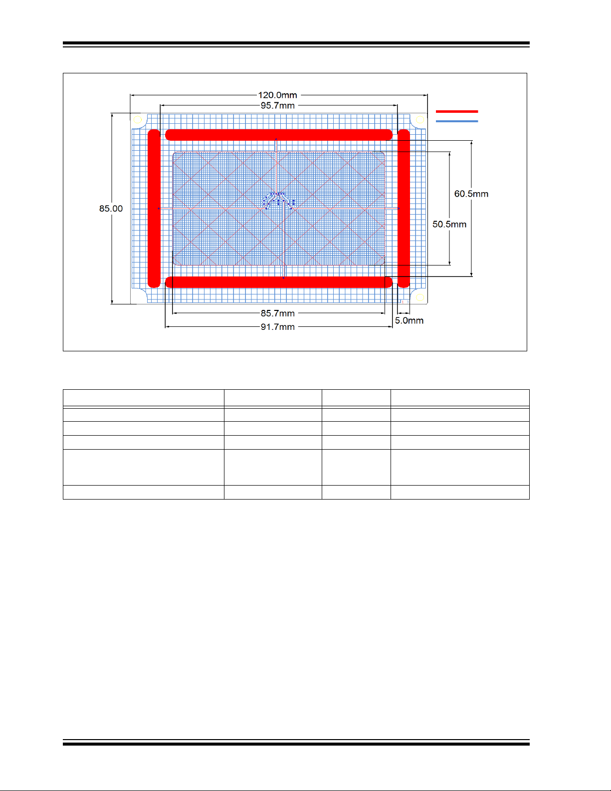
MGC3130 Hillstar Development Kit User’s Guide
FIGURE 3-4: ELECTRODE LAYOUT
TABLE 3-2: HILLSTAR ELECTRODE DIMENSIONS
Length Width Design
Horizontal Electrodes (Rx) 91.7 mm 5 mm solid
Vertical Electrodes (Rx) 70.5 mm 5 mm solid
Center Electrode (Rx) 85.7 mm 50.5 mm 3% cross-hatched
Tx Electrode (refer to Figure 3-4)
Part I (under center electrode)
Part II (outside Part I)
Ground Area 120 mm 85 mm solid
120 mm
85.7 mm
120 mm
85 mm
50.5 mm
85 mm
50% cross-hatched
20% cross-hatched
The electrode PCB is based on a 4-layer PCB design using FR4 material. Three
functional layers are used:
• Layer 1 (Top): Rx electrodes
• Layer 3: Tx electrode and Rx feeding lines
• Layer 4 (Bottom): Ground
Layer 2 is not used.
DS40001721A-page 26 2013 Microchip Technology Inc.
Page 27

Hillstar Boards – Hardware Description
Tx: 35 µm
Tx
Rx : 18 µm
GND: 18 µm
Not Used: 35 µm
0.25 mm
0.15 mm
935 µm
540 µm
1.546 mm
Top layer
Bottom
layer
2ndlayer
3
rd
layer
Rx feeding line
™
FIGURE 3-5: PCB LAYER STACK
In a target system design the GND layer is not required. It is added for the Hillstar sensing electrode as a shielding layer and shall simulate the presence of static components
which are placed in a target device underneath the sensing electrodes.
Note: Please refer to the “MGC3130 GestIC® Design Guide” for the electrodes
equivalent circuitry, capacitances (C
values.
RxTx
, C
RxG
, Tx
) and their typical
RxG
3.4 I2C TO USB BRIDGE
Connecting the MGC3130 Unit to a PC requires an I2C to USB Bridge. The Hillstar
Bridge works as a Composite Device Class (CDC). It controls the USB transfer towards
the host PC and handles the I
provides 3.3V power supply and the MCLR
The bridge function is handled by Microchip’s PIC18F14K50 USB microcontroller.
The board is equipped with a mini USB connector (Type A) and a 2 mm 6-pin female
board-to-board connector for the I
includes the following signals: EIO0, 3.3V, GND, SDA0, SCL0, and MCLR
to Figure 3-6.
FIGURE 3-6: I
2
C™ TO USB BRIDGE
2
C communication with the MGC3130 Unit. Moreover, it
signal to the MGC3130 Unit.
2
C interface. The interface to the MGC3130 Unit
. Please refer
2013 Microchip Technology Inc. DS40001721A-page 27
Page 28

MGC3130 Hillstar Development Kit User’s Guide
PIC18F14K50
RB4
RB6
RC0
RC6
RA0
RA1
SDA
SCL
TS
3.3V
1.8kΩ
10kΩ
1.8kΩ
MCLR
10kΩ
MGC3130
SI0
SI1
EIO0
MCLR
I2CTMto USB BridgeMGC3130 Unit
USB D+
USB D-
USB
I2CTMMasterI2CTMSlave
PC
The I2C to USB Bridge is powered via the USB port. Microchip’s Low Dropout (LDO)
Voltage Regulator MCP1801 is used to transform the 5V USB power to 3.3V required
for the PIC18F14K50. By default, 3.3V are also routed to the MGC3130 Unit via the I
interface. The 3.3V power supply towards the MGC3130 Unit can be cut by removing
the 0 resistor R7.
The LEDs indicate the following:
• POWER – signals that the I
• LED1 – blinks fast (~10 Hz) to indicate that there is no USB connection
established
• LED1 – blinks slow (~1 Hz) to indicate that the USB connection is established
• LED 2 – is on when there is data on the I
• LED 2 – is off when there is no data on the I
The communication between Bridge and MGC3130 Unit is accomplished via a 2-wire
2
I
C compatible serial port. Please refer to Figure 3-7.
In addition, the Hillstar Development Kit integrates an open-drain transfer status line
(TS) and the MGC3130 MCLR
TS is connected to the RC0 pin of the PIC18F14K50 and MCLR
For a detailed description of the I
Gesture Controller Data Sheet” (DS40001667).
The default I
2
C address of the bridge is set to 0x42 but can also be switched to 0x43
by changing the firmware running on the PIC18F14K50.
2
C to USB Bridge is powered (3.3V)
2
C bus
2
C bus
signal, according to the MGC3130 reference circuitry.
to RC6.
2
C interface refer to the “MGC3130 Single-Zone 3D
2
C
FIGURE 3-7: I
Note: To update the PIC18F14K50 firmware, please refer to ‘MGC3130
PIC18F14K50 Host Reference Code’, available on
www.microchip.com/GestICGettingStarted.’
2
C™ AND USB DATA INTERFACE
2
For Schematics, Layout and Bill of Material of the I
C to USB Bridge please refer to
Appendix A.
DS40001721A-page 28 2013 Microchip Technology Inc.
Page 29

Chapter 4. Design In: Hillstar In Target Application
4.1 INTRODUCTION
The Hillstar Development Kit is designed to support an easy integration of Microchip’s
MGC3130 3D Tracking and Gesture Controller into customer’s applications.
The three Hillstar PCBs can be plugged to a PC via USB cable and used for
evaluation of MGC3130 chip and GestIC technology.
During the customer’s design-in process the individual boards can be combined
according to the customers need.
Three examples are given below:
• Combine MGC3130 Unit and I
electrodes
•Use I
circuitry in the customer’s design (in-circuit)
• Combine MGC3130 Unit and Electrodes to develop gesture-driven applications
for PC-based or embedded software environments
For in-circuit parameterization and debugging it is mandatory to control the MGC3130
via Aurea Control Software. For that purpose, the customer’s application should
provide an appropriate hardware or software interface.
MGC3130 HILLSTAR DEVELOPMENT
KIT USER’S GUIDE
2
C to USB Bridge to evaluate customized
2
C to USB Bridge to parameterize and debug the MGC3130 application
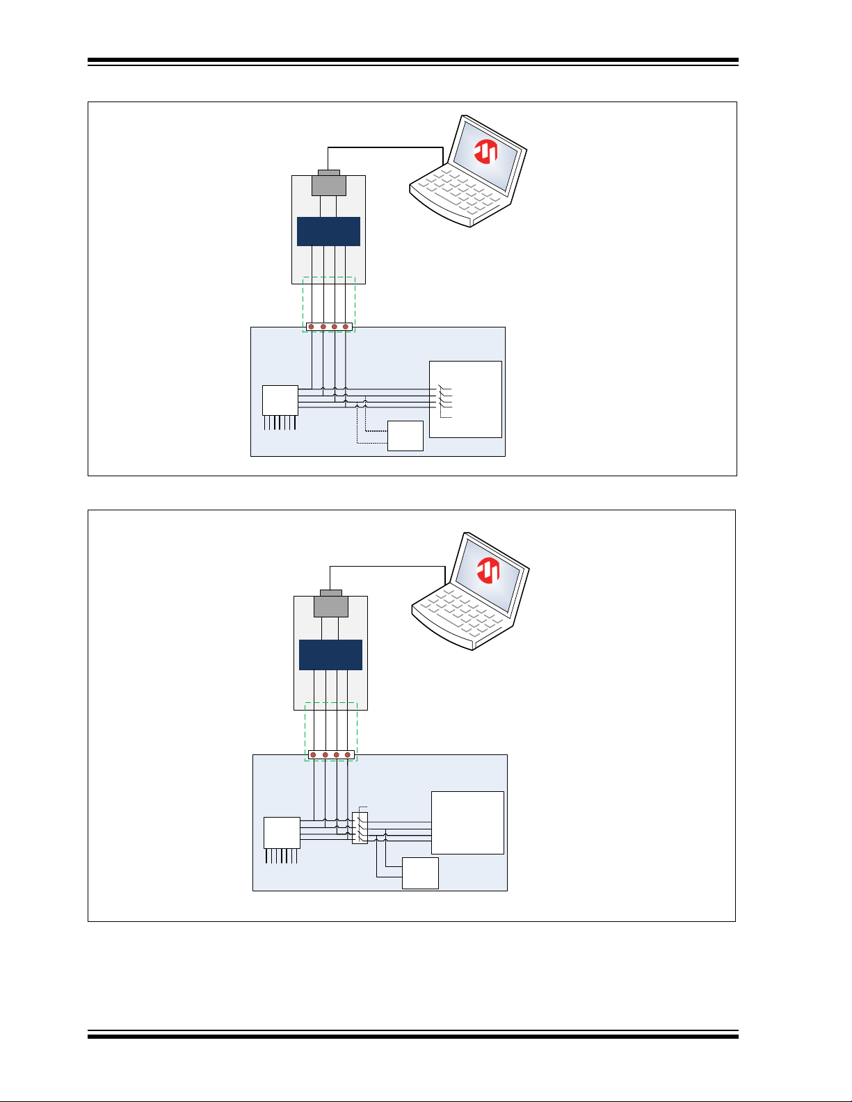
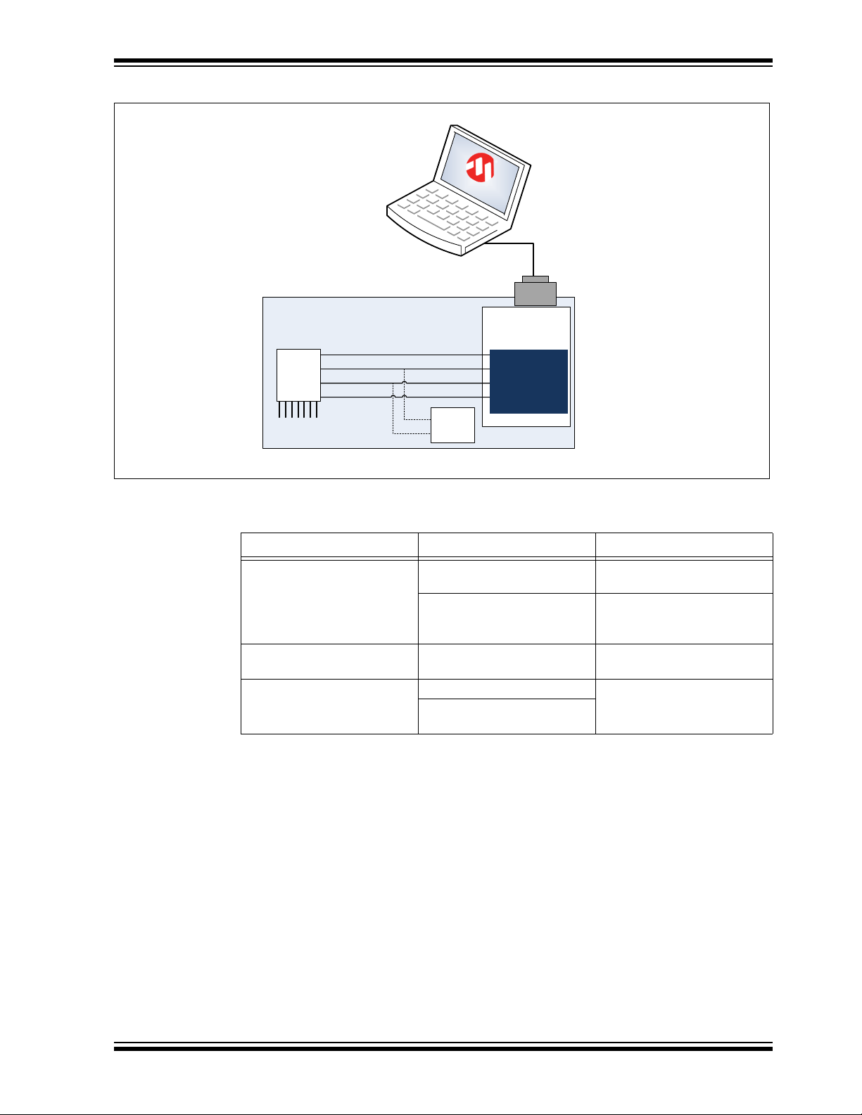
4.2 INTEGRATION EXAMPLES
The following figures show typical hardware circuits for MGC3130 integration into a
customer’s application.
Figure 4-1 and Figure 4-2 show the control via I
to USB Bridge acts as an I
• Switched off (I
• Switched to Slave or Listen mode or
• Disconnected (through an external switch, refer to Figure 4-2)
As an alternative, it is also possible to establish an USB connection between the application processor and a PC without using an I
4-3.
2
C lines configured as high Z, refer to Figure 4-1)
2
2
C master, the application processor I2C should be:
C and an external PC. The Hillstar I2C
2
C to USB Bridge. Please refer to Figure
2013 Microchip Technology Inc. DS40001721A-page 29
Page 30
MGC3130 Hillstar Development Kit User’s Guide
Customer application
Bridge
TS
USB to I²C
(HID)
I²C SCL
I²CtoUSB
Bridge
Application
Processor
USB
Reset
For debugging and
parametetrization
purposes
USB cable
To electrodes
I²C SDA
TS
I²C SDA
I²C SCL
Reset
MGC
3130
High Z for
bridge
access
I2C
client
AUREA
Customer application
Bridge
TS
USB to I²C
(HID)
I²C SCL
I²CtoUSB
Bridge
Application
Processor
USB
Reset
For debugging and
parametetrization
purposes
USB cable
To electrodes
I²C SDA
TS
I²C SDA
I²C SCL
Reset
MGC
3130
I2C
client
AUREA
open for
bridge
access
FIGURE 4-1: MGC3130 PARAMETERIZATION CIRCUIT WITH INTERNAL SWITCH
FIGURE 4-2: MGC3130 PARAMETERIZATION CIRCUIT WITH EXTERNAL SWITCH
DS40001721A-page 30 2013 Microchip Technology Inc.
Page 31
Design In: Hillstar In Target Application
Customer application
Application
Processor
For debugging and
parametetrization
purposes
USB cable
To electrodes
TS
I²C SDA
I²C SCL
Reset
MGC
3130
I2C
client
AUREA
USB to I²C
(CDC/HID)
FIGURE 4-3: MGC3130 PARAMETERIZATION CIRCUIT FOR USB BASED APPLICATIONS
TABLE 4-1: MGC3130 PARAMETERIZATION CIRCUITS COMPARISON
Parameterization Circuit Advantages Drawbacks
With Internal Switch Easy Approach Processor pins need to be
switchable to high Z
Low hardware efforts No other clients can be
controlled during Aurea
access
With External Switch Communication to other I2C™
Additional hardware switch
clients not interrupted
USB Based Applications No hardware efforts Additional software efforts
Works if other I
2
C™ clients
connected to the bus
2013 Microchip Technology Inc. DS40001721A-page 31
Page 32

MGC3130 Hillstar Development Kit User’s Guide
NOTES:
DS40001721A-page 32 2013 Microchip Technology Inc.
Page 33

MGC3130 HILLSTAR DEVELOPMENT
KIT USER’S GUIDE
Chapter 5. Troubleshooting
Troubleshooting Information
Power LED does not illuminate
In case the power LED does not illuminate it is likely that the board is not powered.
Possible Solutions:
• Check the board is connected to your PC’s USB port.
• Change the USB cable or use a different USB port on your PC.
• Check if the PC is switched on.
LED 1 blinks fast
When LED 1 blinks fast (~10 Hz) the USB connection is not established towards the PC.
Possible Solutions:
• Make sure the Windows CDC driver is installed (refer to Appendix D. “Driver Installation Man-
ual”).
• Makes sure the MGC3130 Unit and the I
in the USB connection (refer to Section 2.2 “Step 1: Build-up Development Kit”).
• Reconnect the board by unplugging and plugging in again the USB connection.
Signal streaming stops
Signal stream in Aurea GUI stops when there is no approach towards the sensing area. This behavior is
intended. When using the Aurea GUI, the Wake-up on Approach feature is automatically enabled.
Possible Solutions:
Disable the Wake-up on Approach feature in the Real-Time Control bar of Aurea by unchecking the
Approach Detection/Power Saving check box for continuous signal streaming.
No Position data displayed, Electrode signals are zero
Signal matching parameters have been mismatched and accidentally stored into the Flash.
Possible Solutions:
• Perform “Autoparameterization” in the AFE Parameterization of Aurea Setup tab. Make sure there is
no hand approach towards the electrodes during autoparamterization process.
• Restore the default Signal Matching parameters by re-flashing the original MGC3130 GestIC
Library file.
LED 1 and 2 on I
When LED 1 and LED 2 on the I
is in Bootloader Update mode and therefore not operating code. The PIC18F14K50 will start in Bootloader
Update mode in case the MGC3130 Unit is not connected to the I
Possible Solutions:
• Please disconnect the I2C™ to USB Bridge from USB. Connect the MGC3130 Unit and the I2C™ to
USB Bridge first and then plug in the USB connection.
2
C™ to USB Bridge are off
2
C™ to USB Bridge are off but the power LED is on, the PIC18F14K50
2
C™ to USB Bridge are already connected before plugging
®
2
C™ to USB Bridge.
2013 Microchip Technology Inc. DS40001721A-page 33
Page 34

MGC3130 Hillstar Development Kit User’s Guide
NOTES:
DS40001721A-page 34 2013 Microchip Technology Inc.
Page 35

Appendix A. Schematics
A.1 INTRODUCTION
This appendix contains the MGC3130 Hillstar Development Kit schematic and Bill of
Materials.
A.2 BILL OF MATERIALS
TABLE A-1: I2C™ TO USB BRIDGE BILL OF MATERIALS
Qty. Description Name
1 Connector, Mini USB 5-pin Type B, SMD BU1
1 Connector, 2 mm socket 6-pin, SMD BU2
1 Capacitor, 100 nF, 10%, X7R, SMD 0402 C1
3 Capacitor, 1 µF, 10%, X5R, 10 V, SMD 0402 C2, C3, C5
1 Capacitor, 10 µF, 20%, X5R, 6.3 V, SMD 0603 C4
3 LED, 571 nm, green clear, 0603 SMD D1, D2, D3
1 IC, MCP1801T LDO, Voltage Regulator, 3.3V, 150 mA, 5-Pin SOT-23 IC1
1 IC, PIC18F14K50 USB Flash Microcontroller, 20-Pin SSOP IC2
3 Resistor, 1 kΩ, 1%, 1/16W, SMD 0402 R3, R4, R6
1 Resistor, 150 kΩ, 1%, 1/16W, SMD 0402 R5
1 Resistor, 0 kΩ, 1%, 1/16W, SMD 0603 R7
1 Crystal, 12 MHz, 33 pF, SMD XTAL1
MGC3130 HILLSTAR DEVELOPMENT
KIT USER’S GUIDE
TABLE A-2: HILLSTAR – I2C™ TO USB BRIDGE MOUNTING OPTION
Qty. Description Name
1 Connector, 1 mm FPC 6-pin, SMD ST1
2013 Microchip Technology Inc. DS40001721A-page 35
Page 36

MGC3130 Hillstar Development Kit User’s Guide
TABLE A-3: HILLSTAR – MGC3130 UNIT BILL OF MATERIALS
Qty. Description Name
1 Connector, 2 mm socket 7-pin, SMD BU1
1 Connector, 2 mm header 6-pin, SMD ST1
1 Capacitor, 100 nF, 10%, X7R, SMD 0402 C1
2 Capacitor, 4,7 µF, 20%, X5R, 6.3V, SMD 0402 C2, C3
1 LED, 571 nm green clear, 0603 SMD D2
1 IC, MGC3130, 28-Pin QFN IC1
2 Resistor, 1,8 kΩ, 1%, 1/16W, SMD 0402 R1, R2
8 Resistor, 10 kΩ, 1%, 1/16W, SMD 0603 R4, R6, R7,
R11, R12, R13,
R14, R15
1 Resistor, 0 kΩ, 1%, 1/16W, SMD 0402 R16
1 Resistor, 10 kΩ, 1%, 1/16W, SMD 0402 R17
1 Resistor, 1 kΩ, 1%, 1/16W, SMD 0402 R18
TABLE A-4: HILLSTAR – MGC3130 UNIT MOUNTING OPTION
Qty. Description Name
1 Connector, 1 mm FPC 6-pin, SMD ST3
A-5: HILLSTAR – ELECTRODE BILL OF MATERIALS
Qty. Description Name
1 Connector, 2 mm header 7-pin, SMD ST1
DS40001721A-page 36 2013 Microchip Technology Inc.
Page 37

A.3 BOARD – SCHEMATICS AND LAYOUT
™
FIGURE A-1: HILLSTAR GestIC® UNIT SCHEMATIC
Schematics
2013 Microchip Technology Inc. DS40001721A-page 37
Page 38

MGC3130 Hillstar Development Kit User’s Guide
Top View
Bottom View
™
FIGURE A-2: ASSEMBLY OF MGC3130 UNIT
FIGURE A-3: HILLSTAR I
2
C™ TO USB BRIDGE SCHEMATIC
DS40001721A-page 38 2013 Microchip Technology Inc.
Page 39

FIGURE A-4: ASSEMBLY OF HILLSTAR I2C™ TO USB BRIDGE
Top View
Bottom View
™
Schematics
2013 Microchip Technology Inc. DS40001721A-page 39
Page 40

MGC3130 Hillstar Development Kit User’s Guide
NOTES:
DS40001721A-page 40 2013 Microchip Technology Inc.
Page 41
MGC3130 HILLSTAR DEVELOPMENT
25
36
48
63
88
120
158
204
256
293
319
317
296
285
312
320
299
257
211
164
130
98
76
58
43
34
0
50
100
150
200
250
300
350
400
450
500
signal deviation / digits
distance to West
West -> East
SD North
SD East
SD South
SD West
SD Center
SD: Signal Deviation
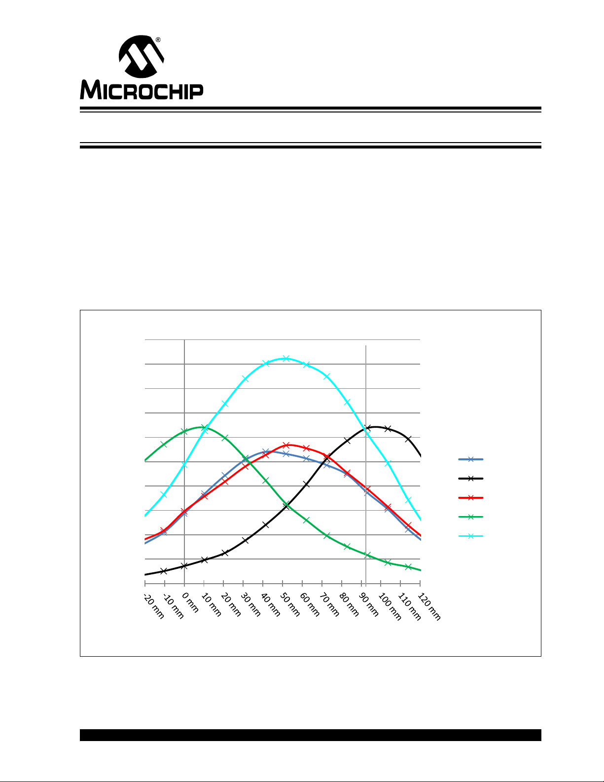
Appendix B. Sensitivity Profile and Capacitances
B.1 INTRODUCTION
This appendix contains the sensitivity profile and the electrode capacitances of the
Hillstar Development Kit hardware.
The measurement procedure of both, the sensitivity profile and the electrode
capacitances are outlined in “MGC3130 GestIC
B.2 SENSITIVITY PROFILES
The sensitivity profiles were conducted using a 40x40x70 mm hand brick and a 30 mm
spacer brick.
FIGURE B-1: SENSITIVITY PROFILE FROM WEST TO EAST
KIT USER’S GUIDE
®
Design Guide”.
2013 Microchip Technology Inc. DS40001721A-page 41
Page 42

MGC3130 Hillstar Development Kit User’s Guide
320
339
354
355
353
329
292
266
227
193
150
131
103
84
64
78
90
110
135
171
207
255
283
319
350
375
382
382
363
334
0
50
100
150
200
250
300
350
400
450
500
signal deviation / digits
distance to North
North -> South
SD North
SD East
SD South
SD West
SD Center
SD: Signal Deviation
FIGURE B-2: SENSITIVITY PROFILE FROM NORTH TO SOUTH
B.3 ELECTRODE CAPACITIES
The capacitances between the Rx electrodes and GND (C
pF input capacitance of the MGC3130 Rx input buffer (C
TABLE B-3: HILLSTAR ELECTRODE CAPACITIES
Channel CRxG CRxTx
North 9 pF 20 pF
East 9 pF 18 pF
South 9 pF 20 pF
West 8 pF 18 pF
Center 7 pF 65 pF
C
TxG
= 590 pF
) does not include the 5
RxG
).
Buf
DS40001721A-page 42 2013 Microchip Technology Inc.
Page 43
MGC3130 HILLSTAR DEVELOPMENT
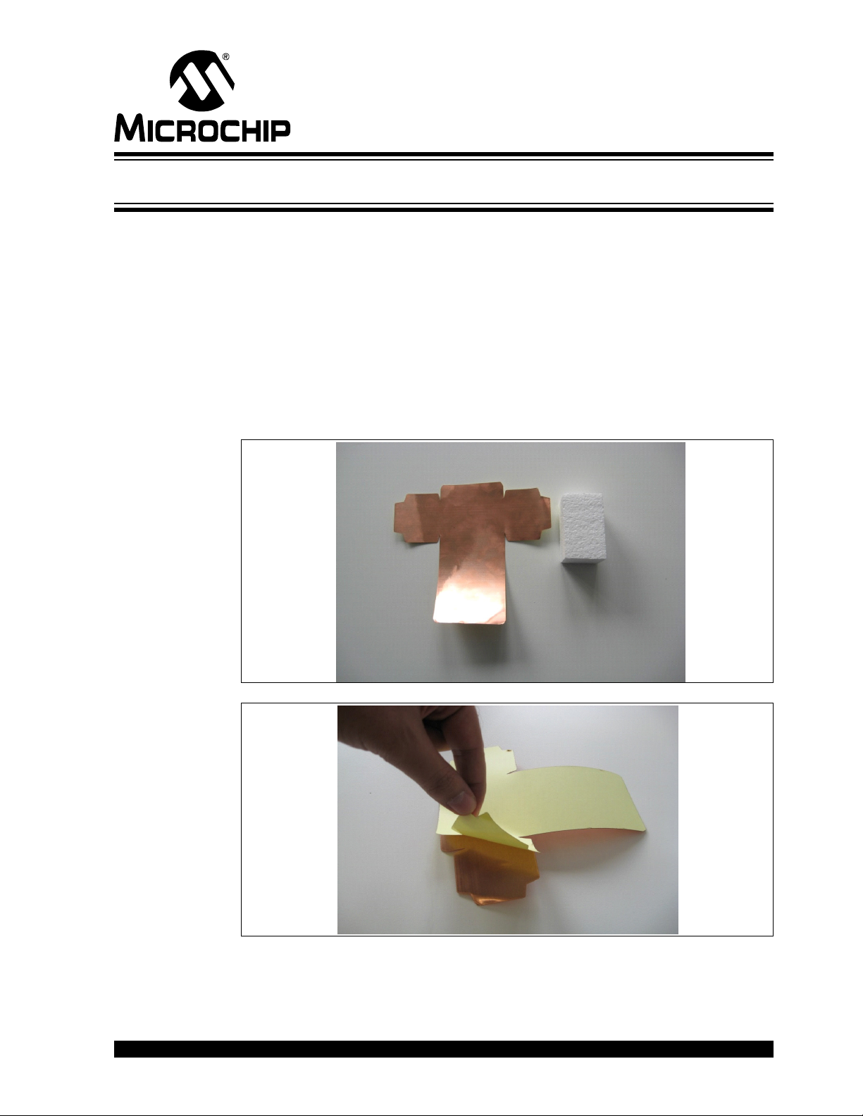
Appendix C. Parameterization Support
C.1 HOW TO BUILD A HAND BRICK
For parameterization and performance evaluation of the customer’s electrode design,
the Hillstar Development Kit contains a set of hand and spacer bricks. The hand brick
is a conductive block of 40x40x70 mm and represents a human hand. It must be
connected to ground via cable in order to simulate the grounding conditions of the
human body.
The Hillstar package contains an assembly set to build the hand brick consisting of a
Styrofoam block (40x40x70 mm) and an adhesive copper foil.
The following section explains how to assemble the hand brick.
1. Take the copper layer and the Styrofoam block with the dimensions of
(40x40x70 mm).
KIT USER’S GUIDE
2. Revert the copper layer and remove the glue foil.
2013 Microchip Technology Inc. DS40001721A-page 43
Page 44
MGC3130 Hillstar Development Kit User’s Guide
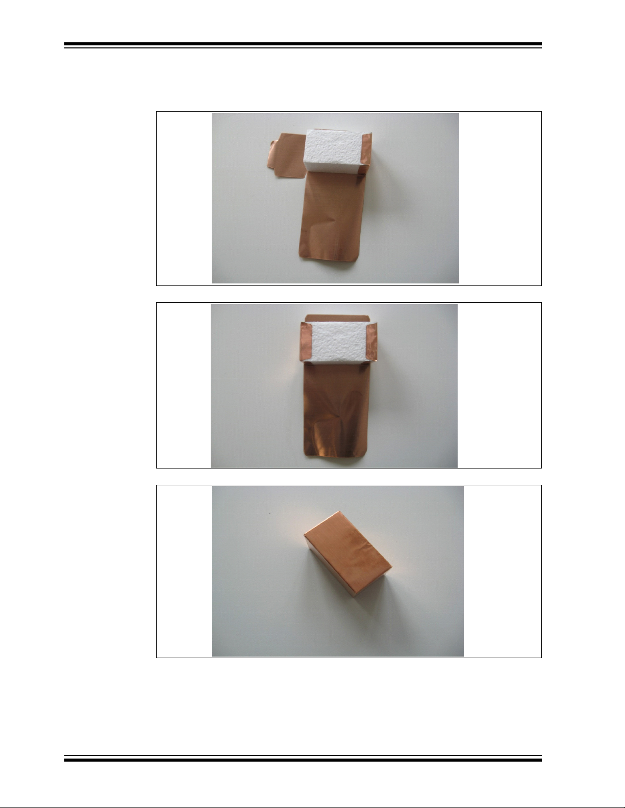
3. Place the Styrofoam block on the copper layer exactly on the middle. Be
careful to be accurate! Fold the copper. Follow along the inside lines, and
fold the copper inward. Start with right, left sides and then with middle part.
Align the folds.
4. Finish up your box. Tape all of the sides together, and you’re done.
DS40001721A-page 44 2013 Microchip Technology Inc.
Page 45

Parameterization Support
Thin wire for grounding (e.g.
0,15mm diameter, 50cm length)
5. Solder a thin wire (approx. 50 cm) on the top of the brick which will be con-
nected later to ground.
6. Finished.
C.2 USAGE OF THE HAND BRICK AS ARTIFICIAL HAND
For parameterization and performance evaluation purposes of the customer’s
electrode design, the kit contains a set of hand and spacer bricks. This artificial hand
brick simulates Human Hand effect and is made of a Styrofoam block covered with light
copper and has a fixed size. Spacer bricks (Styrofoam block without copper layer) are
used to position the hand brick in different heights to the electrode. Because of a εr≈1of
Styrofoam, the spacer brick does not influence the measurement results.
For quick parameterization, the ground wire connected to the hand brick should be
maintained using your hand which emulates the ground connection. The wire should
be hold at 50 cm minimum and the line should also be straight to avoid any influence
to the system sensitivity as shown in Figure C-1.
For parameterization process, please refer to “MGC3130 GestIC
the appropriate wizards in Aurea PC software.
®
Design Guide” and
2013 Microchip Technology Inc. DS40001721A-page 45
Page 46

MGC3130 Hillstar Development Kit User’s Guide
FIGURE C-1: USAGE OF ARTIFICIAL HAND
DS40001721A-page 46 2013 Microchip Technology Inc.
Page 47

MGC3130 HILLSTAR DEVELOPMENT
Appendix D. Driver Installation Manual
Go through the following steps to manually install the Windows CDC Driver on your PC.
D.1 OPEN DEVICE MANAGER
While the Hillstar Development Board is connected to your PC press Start, right-click
on Computers and select Manage. This will bring up the Computer Management
window shown in Figure D-1. On the left sidebar select Device Manager.
FIGURE D-1: COMPUTER MANAGEMENT
KIT USER’S GUIDE
D.2 SELECT DEVICE
1. Right Click on GestIC Bridge and select Update Driver Software.
2. Select Search Method
3. The window shown in Figure D-2 will open. Choose Browse my Computer for
driver software.
2013 Microchip Technology Inc. DS40001721A-page 47
Page 48

MGC3130 Hillstar Development Kit User’s Guide
FIGURE D-2: Update Driver Software
D.3 LOCATE DRIVER
1. Click Browse and navigate to the driver files on your local drive (refer to
Figure D-3).
2. Press Next and the driver will be installed.
FIGURE D-3: Browse for Driver Software
D.4 VERIFY COMMUNICATION
The driver is properly installed and the communication between the PC and the Hillstar
Development Board is successfully established when LED 1 and LED 2 blink
alternatively.
DS40001721A-page 48 2013 Microchip Technology Inc.
Page 49

MGC3130 HILLSTAR DEVELOPMENT
KIT USER’S GUIDE
Appendix E. Glossary
TABLE E-1: GestIC® GLOSSARY
Term Definition
AFE Analog front end
Application Host PC or embedded controller which controls the MGC3130
Aurea MGC3130 PC control software with graphical user interface
®
Colibri Suite Embedded DSP suite within the GestIC
Deep Sleep MGC3130 Power-Saving mode
E-field Electrical field
Frame Electrodes Rectangular set of four electrodes for E-field sensing
®
GestIC
GestIC
Gesture Recognition Microchip’s stochastic HMM classifier to automatically detect and
Gesture Set A set of provided hand movement patterns
Hand Brick Copper coated test block (40x40x70 mm)
HMM Hidden Markov Model
MGC3130 Single-Zone 3D Gesture Sensing Controller
Position Tracking GestIC
Sabrewing MGC3130 evaluation board
Self Wake-up MGC3130 Power-Saving mode
Sensing Area Area enclosed by the four frame electrodes
Sensing Space Space above sensing area
Signal Deviation Term for the delta of the sensor signal on approach of the hand
Spacer Brick Spacer between the sensor layer and hand brick
SPU Signal Processing Unit
Approach Detection GestIC
Technology Microchip’s patented technology providing 3D free-space gesture
recognition utilizing the principles of electrical near-field sensing
®
Library Includes the implementation of MGC3130 features and is delivered
as a binary file preprogrammed on the MGC3130
classify hand movement patterns
®
technology feature
versus non-approach
(Styrofoam block 40x40xh mm) with h= 1 / 2 / 3 / 5 / 8 / 12 cm
®
technology feature: Power-Saving mode of the MGC3130
with approach detection
Library
2013 Microchip Technology Inc. DS40001721A-page 49
Page 50

Worldwide Sales and Service
AMERICAS
Corporate Office
2355 West Chandler Blvd.
Chandler, AZ 85224-6199
Tel: 480-792-7200
Fax: 480-792-7277
Technical Support:
http://www.microchip.com/
support
Web Address:
www.microchip.com
Atlanta
Duluth, GA
Tel: 678-957-9614
Fax: 678-957-1455
Boston
Westborough, MA
Tel: 774-760-0087
Fax: 774-760-0088
Chicago
Itasca, IL
Tel: 630-285-0071
Fax: 630-285-0075
Cleveland
Independence, OH
Tel: 216-447-0464
Fax: 216-447-0643
Dallas
Addison, TX
Tel: 972-818-7423
Fax: 972-818-2924
Detroit
Farmington Hills, MI
Tel: 248-538-2250
Fax: 248-538-2260
Indianapolis
Noblesville, IN
Tel: 317-773-8323
Fax: 317-773-5453
Los Angeles
Mission Viejo, CA
Tel: 949-462-9523
Fax: 949-462-9608
Santa Clara
Santa Clara, CA
Tel: 408-961-6444
Fax: 408-961-6445
Toronto
Mississauga, Ontario,
Canada
Tel: 905-673-0699
Fax: 905-673-6509
ASIA/PACIFIC
Asia Pacific Office
Suites 3707-14, 37th Floor
Tower 6, The Gateway
Harbour City, Kowloon
Hong Kong
Tel: 852-2401-1200
Fax: 852-2401-3431
Australia - Sydney
Tel: 61-2-9868-6733
Fax: 61-2-9868-6755
China - Beijing
Tel: 86-10-8569-7000
Fax: 86-10-8528-2104
China - Chengdu
Tel: 86-28-8665-5511
Fax: 86-28-8665-7889
China - Chongqing
Tel: 86-23-8980-9588
Fax: 86-23-8980-9500
China - Hangzhou
Tel: 86-571-2819-3187
Fax: 86-571-2819-3189
China - Hong Kong SAR
Tel: 852-2943-5100
Fax: 852-2401-3431
China - Nanjing
Tel: 86-25-8473-2460
Fax: 86-25-8473-2470
China - Qingdao
Tel: 86-532-8502-7355
Fax: 86-532-8502-7205
China - Shanghai
Tel: 86-21-5407-5533
Fax: 86-21-5407-5066
China - Shenyang
Tel: 86-24-2334-2829
Fax: 86-24-2334-2393
China - Shenzhen
Tel: 86-755-8864-2200
Fax: 86-755-8203-1760
China - Wuhan
Tel: 86-27-5980-5300
Fax: 86-27-5980-5118
China - Xian
Tel: 86-29-8833-7252
Fax: 86-29-8833-7256
China - Xiamen
Tel: 86-592-2388138
Fax: 86-592-2388130
China - Zhuhai
Tel: 86-756-3210040
Fax: 86-756-3210049
ASIA/PACIFIC
India - Bangalore
Tel: 91-80-3090-4444
Fax: 91-80-3090-4123
India - New Delhi
Tel: 91-11-4160-8631
Fax: 91-11-4160-8632
India - Pune
Tel: 91-20-3019-1500
Japan - Osaka
Tel: 81-6-6152-7160
Fax: 81-6-6152-9310
Japan - Tokyo
Tel: 81-3-6880- 3770
Fax: 81-3-6880-3771
Korea - Daegu
Tel: 82-53-744-4301
Fax: 82-53-744-4302
Korea - Seoul
Tel: 82-2-554-7200
Fax: 82-2-558-5932 or
82-2-558-5934
Malaysia - Kuala Lumpur
Tel: 60-3-6201-9857
Fax: 60-3-6201-9859
Malaysia - Penang
Tel: 60-4-227-8870
Fax: 60-4-227-4068
Philippines - Manila
Tel: 63-2-634-9065
Fax: 63-2-634-9069
Singapore
Tel: 65-6334-8870
Fax: 65-6334-8850
Taiwan - Hsin Chu
Tel: 886-3-5778-366
Fax: 886-3-5770-955
Taiwan - Kaohsiung
Tel: 886-7-213-7828
Fax: 886-7-330-9305
Taiwan - Taipei
Tel: 886-2-2508-8600
Fax: 886-2-2508-0102
Thailand - Bangkok
Tel: 66-2-694-1351
Fax: 66-2-694-1350
EUROPE
Austria - Wels
Tel: 43-7242-2244-39
Fax: 43-7242-2244-393
Denmark - Copenhagen
Tel: 45-4450-2828
Fax: 45-4485-2829
France - Paris
Tel: 33-1-69-53-63-20
Fax: 33-1-69-30-90-79
Germany - Munich
Tel: 49-89-627-144-0
Fax: 49-89-627-144-44
Italy - Milan
Tel: 39-0331-742611
Fax: 39-0331-466781
Netherlands - Drunen
Tel: 31-416-690399
Fax: 31-416-690340
Spain - Madrid
Tel: 34-91-708-08-90
Fax: 34-91-708-08-91
UK - Wokingham
Tel: 44-118-921-5869
Fax: 44-118-921-5820
08/20/13
DS40001721A-page 50 2013 Microchip Technology Inc.
 Loading...