

Page 1
MCP7386X
Battery Charger
Evaluation Board
User’s Guide
© 2006 Microchip Technology Inc. DS51475C
Page 2
Note the following details of the code protection feature on Microchip devices:
• Microchip products meet the specification contained in their particular Microchip Data Sheet.
• Microchip believes that its family of products is one of the most secure families of its kind on the market today, when used in the
intended manner and under normal conditions.
• There are dishonest and possibly illegal methods used to breach the code protection feature. All of these methods, to our
knowledge, require using the Microchip products in a manner outside the operating specifications contained in Microchip’s Data
Sheets. Most likely, the person doing so is engaged in theft of intellectual property.
• Microchip is willing to work with the customer who is concerned about the integrity of their code.
• Neither Microchip nor any other semiconductor manufacturer can guarantee the security of their code. Code protection does not
mean that we are guaranteeing the product as “unbreakable.”
Code protection is constantly evolving. We at Microchip are committed to continuously improving the code protection features of our
products. Attempts to break Microchip’s code protection feature may be a violation of the Digital Millennium Copyright Act. If such acts
allow unauthorized access to your software or other copyrighted work, you may have a right to sue for relief under that Act.
Information contained in this publication regarding device
applications and the like is provided only for your convenience
and may be superseded by updates. It is your responsibility to
ensure that your application meets with your specifications.
MICROCHIP MAKES NO REPRESENTATIONS OR
WARRANTIES OF ANY KIND WHETHER EXPRESS OR
IMPLIED, WRITTEN OR ORAL, STATUTORY OR
OTHERWISE, RELATED TO THE INFORMATION,
INCLUDING BUT NOT LIMITED TO ITS CONDITION,
QUALITY, PERFORMANCE, MERCHANTABILITY OR
FITNESS FOR PURPOSE. Microchip disclaims all liability
arising from this information and its use. Use of Microchip
devices in life support and/or safety applications is entirely at
the buyer’s risk, and the buyer agrees to defend, indemnify and
hold harmless Microchip from any and all damages, claims,
suits, or expenses resulting from such use. No licenses are
conveyed, implicitly or otherwise, under any Microchip
intellectual property rights.
Trademarks
The Microchip name and logo, the Microchip logo, Accuron,
dsPIC, K
EELOQ, microID, MPLAB, PIC, PICmicro, PICSTART,
PRO MATE, PowerSmart, rfPIC and SmartShunt are
registered trademarks of Microchip Technology Incorporated
in the U.S.A. and other countries.
AmpLab, FilterLab, Migratable Memory, MXDEV, MXLAB,
SEEVAL, SmartSensor and The Embedded Control Solutions
Company are registered trademarks of Microchip Technology
Incorporated in the U.S.A.
Analog-for-the-Digital Age, Application Maestro, CodeGuard,
dsPICDEM, dsPICDEM.net, dsPICworks, ECAN,
ECONOMONITOR, FanSense, FlexROM, fuzzyLAB,
In-Circuit Serial Programming, ICSP, ICEPIC, Linear Active
Thermistor, Mindi, MiWi, MPASM, MPLIB, MPLINK, PICkit,
PICDEM, PICDEM.net, PICLAB, PICtail, PowerCal,
PowerInfo, PowerMate, PowerTool, REAL ICE, rfLAB,
rfPICDEM, Select Mode, Smart Serial, SmartTel, Total
Endurance, UNI/O, WiperLock and ZENA are trademarks of
Microchip Technology Incorporated in the U.S.A. and other
countries.
SQTP is a service mark of Microchip Technology Incorporated
in the U.S.A.
All other trademarks mentioned herein are property of their
respective companies.
© 2006, Microchip Technology Incorporated, Printed in the
U.S.A., All Rights Reserved.
Printed on recycled paper.
Microchip received ISO/TS-16949:2002 certification for its worldwide
headquarters, design and wafer fabrication facilities in Chandler and
Tempe, Arizona, Gresham, Oregon and Mountain View, California. The
Company’s quality system processes and procedures are for its
PICmicro
EEPROMs, microperipherals, nonvolatile memory and analog
products. In addition, Microchip’s quality system for the design and
manufacture of development systems is ISO 9001:2000 certified.
®
8-bit MCUs, KEELOQ
®
code hopping devices, Serial
DS51475C-page ii © 2006 Microchip Technology Inc.
Page 3
MCP7386X EVALUATION
BOARD USER’S GUIDE
Table of Contents
Preface ........................................................................................................................... 1
Chapter 1. Product Overview
1.1 Introduction and Highlights ............................................................................. 5
1.2 What is the MCP7386X Battery Charger Evaluation Board? ......................... 5
1.3 What the MCP7386X Battery Charger Evaluation Board Includes ................ 5
Chapter 2. Installation and Operation
2.1 Features ......................................................................................................... 7
2.2 Getting Started ............................................................................................... 7
2.3 Detailed Description ....................................................................................... 8
Appendix A. Schematic and Layouts
A.1 Introduction .................................................................................................. 11
A.2 Board Schematic ........................................................................................ 12
A.3 Board – Top Layer ..................................................................................... 13
A.4 Board – Silk Screen Layer ......................................................................... 14
A.5 Board – Bottom Layer ................................................................................ 15
Appendix B. Bill Of Materials (BOM)
Worldwide Sales and Service .................................................................................... 18
© 2006 Microchip Technology Inc. DS51475C-page iii
Page 4

MCP7386X Evaluation Board User’s Guide
NOTES:
DS51475C-page iv © 2006 Microchip Technology Inc.
Page 5
MCP7386X EVALUATION
BOARD USER’S GUIDE
Preface
NOTICE TO CUSTOMERS
All documentation becomes dated, and this manual is no exception. Microchip tools and
documentation are constantly evolving to meet customer needs, so some actual dialogs
and/or tool descriptions may differ from those in this document. Please refer to our web site
(www.microchip.com) to obtain the latest documentation available.
Documents are identified with a “DS” number. This number is located on the bottom of each
page, in front of the page number. The numbering convention for the DS number is
“DSXXXXXA”, where “XXXXX” is the document number and “A” is the revision level of the
document.
INTRODUCTION
This chapter contains general information that will be useful to know before using the
MCP7386X Battery Charger Evaluation Board. Items discussed in this chapter include:
• Document Layout
• Conventions Used in this Guide
• Recommended Reading
• The Microchip Web Site
• Customer Support
• Document Revision History
DOCUMENT LAYOUT
This document describes how to use the MCP7386X Battery Charger Evaluation Board
as a development tool to emulate and debug firmware on a target board. The manual
layout is as follows:
• Chapter 1. “Product Overview” – Important information about the MCP7386X
Battery Charger Evaluation Board.
• Chapter 2. “Installation and Operation” – For users evaluating the
MCP73861/2/3/4 devices, this chapter describes how to use the various features
of the hardware.
• Appendix A. “Schematic and Layouts” – Shows the schematic and layout
diagrams for the MCP7386X Battery Charger Evaluation Board.
• Appendix B. “Bill Of Materials (BOM)” – Lists the parts used to build the
MCP7386X Battery Charger Evaluation Board.
© 2006 Microchip Technology Inc. DS51475C-page 1
Page 6
MCP7386X Evaluation Board User’s Guide
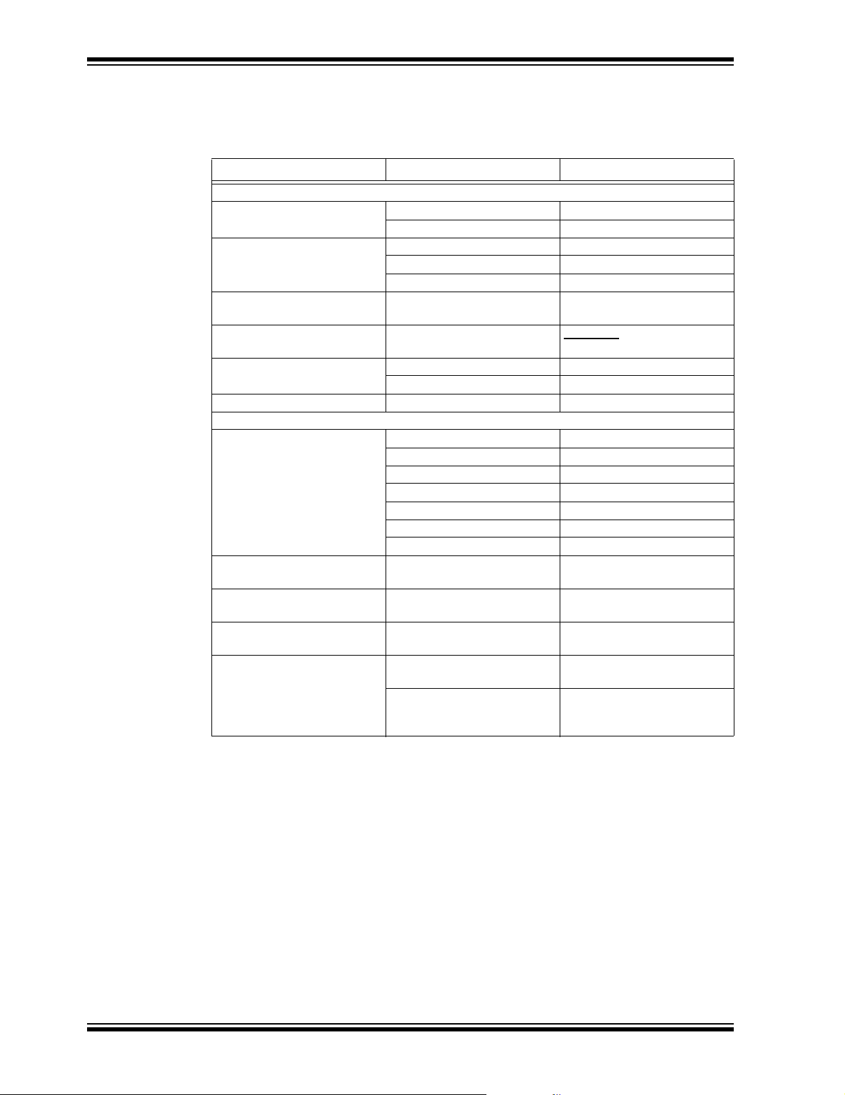
CONVENTIONS USED IN THIS GUIDE
This manual uses the following documentation conventions:
DOCUMENTATION CONVENTIONS
Description Represents Examples
Arial font:
Italic characters Referenced books MPLAB® IDE User’s Guide
Emphasized text ...is the only compiler...
Initial caps A window the Output window
A dialog the Settings dialog
A menu selection select Enable Programmer
Quotes A field name in a window or
dialog
Underlined, italic text with
right angle bracket
Bold characters A dialog button Click OK
Text in angle brackets < > A key on the keyboard Press <Enter>, <F1>
Courier New font:
Plain Courier New Sample source code #define START
Italic Courier New A variable argument file.o, where file can be
Square brackets [ ] Optional arguments mcc18 [options] file
Curly brackets and pipe
character: { | }
Ellipses... Replaces repeated text var_name [,
A menu path File>Save
A tab Click the Power tab
Filenames autoexec.bat
File paths c:\mcc18\h
Keywords _asm, _endasm, static
Command-line options -Opa+, -Opa-
Bit values 0, 1
Constants 0xFF, ‘A’
Choice of mutually exclusive
arguments; an OR selection
Represents code supplied by
user
“Save project before build”
any valid filename
[options]
errorlevel {0|1}
var_name...]
void main (void)
{ ...
}
RECOMMENDED READING
This user's guide describes how to use the MCP7386X Battery Charger Evaluation
Board. Other useful documents are listed below. The following Microchip documents
are available and recommended as supplemental reference resources.
MCP73861/2/3/4 Data Sheet, “Advanced Single or Dual-Cell, Fully-Integrated
Li-Ion/Li-Polymer Charge Management Controllers” (DS21893)
This data sheet provides detailed information regarding the MCP73861 Advanced
Single or Dual-Cell, Fully-Integrated, Lithium-Ion/Lithium-Polymer Charge
Management Controllers.
DS51475C-page 2 © 2006 Microchip Technology Inc.
Page 7

THE MICROCHIP WEB SITE
Microchip provides online support via our web site at www.microchip.com. This web
site is used as a means to make files and information easily available to customers.
Accessible by using your favorite Internet browser, the web site contains the following
information:
• Product Support – Data sheets and errata, application notes and sample
programs, design resources, user’s guides and hardware support documents,
latest software releases and archived software
• General Technical Support – Frequently Asked Questions (FAQs), technical
support requests, online discussion groups, Microchip consultant program
member listing
• Business of Microchip – Product selector and ordering guides, latest Microchip
press releases, listing of seminars and events, listings of Microchip sales offices,
distributors and factory representatives
CUSTOMER SUPPORT
Users of Microchip products can receive assistance through several channels:
• Distributor or Representative
• Local Sales Office
• Field Application Engineer (FAE)
• Technical Support
• Development Systems Information Line
Customers should contact their distributor, representative or field application engineer
(FAE) for support. Local sales offices are also available to help customers. A listing of
sales offices and locations is included in the back of this document.
Technical support is available through the web site at: http://support.microchip.com
Preface
DOCUMENT REVISION HISTORY
Revision C (July 2006)
• Add disclaimer to Bill of Materials regarding RoHS-Compliant part numbers.
Revision B (September 2005)
• Added References to MCP73861/2/3/4.
Revision A (June 2004)
• Initial Release of this Document.
© 2006 Microchip Technology Inc. DS51475C-page 3
Page 8

MCP7386X Evaluation Board User’s Guide
NOTES:
DS51475C-page 4 © 2006 Microchip Technology Inc.
Page 9

MCP7386X EVALUATION
BOARD USER’S GUIDE
Chapter 1. Product Overview
1.1 INTRODUCTION
This chapter provides an overview of the MCP7386X Battery Charger Evaluation Board
and covers the following topics:
• What is the MCP7386X Battery Charger Evaluation Board?
• What the MCP7386X Battery Charger Evaluation Board Includes
1.2 WHAT IS THE MCP7386X BATTERY CHARGER EVALUATION BOARD?
The MCP7386X Battery Charger Evaluation Board is an evaluation and demonstration
tool for Microchip Technology’s MCP7386X Advanced Single or Dual-Cell,
Fully-Integrated, Lithium-Ion/Lithium-Polymer Charge Management Controllers. The
design provides for dynamic versatility while being able to handle accurate
measurements.
When connected, this evaluation board allows for the evaluation of the MCP7386X
devices in a variety of applications.
1.3 WHAT THE MCP7386X BATTERY CHARGER EVALUATION BOARD INCLUDES
This MCP7386X Battery Charger Evaluation Board Kit includes:
• The MCP7386X Battery Charger Evaluation Board
• MCP73861 Device (Installed)
• Analog and Interface Products Demonstration Boards CD-ROM (DS21912)
- MCP7386X Battery Charger Evaluation Board User’s Guide
© 2006 Microchip Technology Inc. DS51475C-page 5
Page 10

MCP7386X Evaluation Board User’s Guide
NOTES:
DS51475C-page 6 © 2006 Microchip Technology Inc.
Page 11

Chapter 2. Installation and Operation
2.1 FEATURES
The MCP7386X Battery Charger Evaluation Board has the following features:
• Evaluation of MCP7386X devices in 4 x 4, 16-lead QFN packages
• Simple, stand-alone operation or microcontroller-compatible
• Powered from external bench supply or wall cube
• Surface-mount design
• Fully assembled and tested
2.2 GETTING STARTED
The MCP7386X Battery Charger Evaluation Board is a fully-functional, assembled and
tested surface-mount board for evaluation of Microchip’s MCP7386X Advanced Single
or Dual-Cell, Fully Integrated Lithium-Ion/Lithium-Polymer Charge Management
Controllers. The following steps provide simple, stand-alone operation. Refer to
Figure 2-1 for the setup configuration diagram. The setup configuration diagram
depicts evaluation of the installed MCP73861 for single-cell applications.
1. Connect an external bench supply or wall cube to the surface-mount test points
provided. The input voltage source should be in the range of 5V to 12V. Refer to
Section 2.3.1 “Input Source” for details on the input source requirements.
MCP7386X EVALUATION
BOARD USER’S GUIDE
Note: Observe correct polarity of connection. Positive terminal connects to J2
(V
+); negative terminal connects to J3 (VIN–).
IN
2. Connect a single-cell Lithium-Ion or Lithium-Polymer battery pack to the circuit
for evaluation.
Note: Observe correct polarity of connection. Positive terminal connects to J5
(V
+); negative terminal connects to J6 (V
BAT
3. Connect an external battery pack thermistor to the J7 (THERM) input. The
thermistor should be connected from J7 (THERM) to J6 (V
cell temperature monitoring is not desired, place a 10 kΩ resistor from THERM
to V
4. Turn on the bench supply or plug in the wall cube.
5. A green LED (D
indicates a Fault condition. Refer to the MCP73861/2/3/4 data sheet (DS21893)
for details.
–, or populate R5 with a 10 kΩ resistor.
BAT
) provides status during the charge cycle. A red LED (D2)
1
BAT
–).
–). If continuous
BAT
© 2006 Microchip Technology Inc. DS51475C-page 7
Page 12

MCP7386X Evaluation Board User’s Guide
Unregulated
Wall Cube
FIGURE 2-1: Setup Configuration Diagram.
2.3 DETAILED DESCRIPTION
The MCP7386X Battery Charger Evaluation Board is set up to evaluate simple,
stand-alone, linear charging of single/dual-cell Lithium-Ion/Lithium-Polymer battery
packs. The reference design provides constant current charging, followed by constant
voltage charging with automatic charge termination. As provided, the MCP7386X
Battery Charger Evaluation Board is set for a fast charge, constant current level of
1.2A, typical for single-cell applications. The MCP73861 is provided in a 4 x 4, 16-lead
QFN package and is equipped with shutdown control, status indicator, fault indicator,
safety timer and a continuous cell temperature monitor. For dual-cell applications, the
MCP73862 or MCP73864 can be substituted for the MCP73861. Refer to the
MCP73861/2/3/4 data sheet (DS21893) for details on the individual device features.
+
Single
Lithium-Ion
-
Cell
2.3.1 Input Source
The MCP7386X Battery Charger Evaluation Board is designed to provide a fast charge
current of 1.2A, typical. The input source should provide a voltage in the range of 5V to
12V. The input source should be capable of providing a minimum of 7.5W.
Lower peak currents can be obtained by adjusting the value of the charge programming
resistors (R
). A corresponding lower-power input source may then be utilized. Refer
2
to the MCP73861/2/3/4 data sheet (DS21893) for details on determining the
appropriate programming resistor.
2.3.2 Safety Timer Periods
The MCP7386X Battery Charger Evaluation Board can be used with a variety of battery
packs. As provided, the MCP7386X Battery Charger Evaluation Board is set up to
perform well with single-cell, 1000 mAh battery packs. Battery packs with alternative
capacities and various charge currents can be implemented. The safety timer periods
may need to be adjusted in order to ensure a full charge. The safety timer periods can
be adjusted by changing the capacitance of C
. Refer to the MCP73861/2/3/4 data
3
sheet (DS21893) for details on determining the appropriate timer capacitance.
2.3.3 Disable Control
The MCP7386X Battery Charger Evaluation Board is designed to provide stand-alone
operation. The installed MCP73861 device is enabled whenever the input source is
present. To disable charging, a jumper can be placed between J1, EN and J3 (V
–).
IN
DS51475C-page 8 © 2006 Microchip Technology Inc.
Page 13

Installation and Operation
2.3.4 Battery Headers
Independent battery connections are provided. The battery pack positive terminal
should be connected to J5 (V
connected to J6 (V
+25°C NTC thermistor, situated in the battery pack for temperature sensing. When the
cell temperature is between -5°C and +55°C, installed resistors provide a charging
window when a thermistor with a sensitivity index (β) of 3982 is utilized. Charging is
inhibited when the cell temperature deviates outside the preset window. The resistor
values can be adjusted to provide the desired charging window for a variety of
thermistors. Refer to the MCP73861/2/3/4 data sheet (DS21893) for details.
Note: Improper connection of the battery may result in damage to the battery
and increase the possibility of personal injury. It is also important to avoid
shorting the battery terminals together.
–). In addition, a connection is provided for a nominal 10 kΩ at
BAT
2.3.5 Device Support Options
The MCP7386X Battery Charger Evaluation Board supports the entire MCP7386X
family. The MCP7386X Battery Charger Evaluation Board is provided with one
reference design utilizing the MCP73861. Alternate devices can be substituted in
order to evaluate the different MCP7386X family options.
+). The battery pack negative terminal should be
BAT
2.3.6 Microcontroller Option
Connection points provide easily-accessible locations for interface to a host
microcontroller. The host microcontroller can be used to disable the charger, monitor
charge status or terminate a charge.
2.3.7 Output Voltage Options
The MCP7386X Battery Charger Evaluation Board is provided with a
Constant-Voltage mode output voltage of 4.2V per cell, the evaluation of which can be
achieved by moving resistor R
to R3, or by shorting the R3 pads.
4
© 2006 Microchip Technology Inc. DS51475C-page 9
Page 14

MCP7386X Evaluation Board User’s Guide
NOTES:
DS51475C-page 10 © 2006 Microchip Technology Inc.
Page 15

Appendix A. Schematic and Layouts
A.1 INTRODUCTION
This appendix contains the following schematics and layouts for the MCP7386X
Evaluation Board:
• Board Schematic
• Board – Top Layer
• Board – Silk Screen Layer
• Board – Bottom Layer
MCP7386X EVALUATION
BOARD USER’S GUIDE
© 2006 Microchip Technology Inc. DS51475C-page 11
Page 16

MCP7386X Evaluation Board User’s Guide
A.2 BOARD SCHEMATIC
J5
U1
1
11
10
VBAT1
VDD1
2
VBAT+
C2
4.7uF
4
13
12
VSS1
VBAT2
VBAT3
VDD23STAT1
STAT215VSET
1
16
17
VSS2
EXPAD
EN
14
J6
9
VSS3
TIMER
8
1
7
6
THERM
PROG
5
VBAT-
THREF
MCP73861/QFN(16)
1
J7
THERM
R5
DNP
R6
6.19k
R7
7.32k
1
J4
PROG
R2
0
D1
GREEN
D2
RED
R4
100k
R8
100k
R1
1.50k
C1
4.7uF
1
J2
VIN+
1
J3
R3
DNP
C3
0.1uF
EN
1
J8
TIMER
1
VIN-
J1
DS51475C-page 12 © 2006 Microchip Technology Inc.
Page 17

A.3 BOARD – TOP LAYER
Schematic and Layouts
© 2006 Microchip Technology Inc. DS51475C-page 13
Page 18

MCP7386X Evaluation Board User’s Guide
A.4 BOARD – SILK SCREEN LAYER
DS51475C-page 14 © 2006 Microchip Technology Inc.
Page 19

A.5 BOARD – BOTTOM LAYER
Schematic and Layouts
© 2006 Microchip Technology Inc. DS51475C-page 15
Page 20

MCP7386X Evaluation Board User’s Guide
NOTES:
DS51475C-page 16 © 2006 Microchip Technology Inc.
Page 21

MCP7386X EVALUATION
BOARD USER’S GUIDE
Appendix B. Bill Of Materials (BOM)
TABLE B-1: BILL OF MATERIALS (BOM)
Qty Designator Description Manufacturer Part Number
®
Opto/
®
®
ECJ-2FB1C475K
SML-LXT0805GW
SML-LXT0805SRW
5016
MCP73861-I/MLG
2 C1, C2 4.7 µF, X5R Ceramic, 16V, 0805 Panasonic
1 C3 0.1 µF, X7R Ceramic, 16V, 0805 Panasonic ECJ-2VB1C104K
1 D1 Green LED, 0805 Lumex
Components Inc.
1 D2 Red LED, 0805 Lumex Opto/
Components Inc.
8 J1 - J8 Surface-Mount Test Point, 5016 Keystone
Electronics
1R1 1.5kΩ, 1/8W, Chip Resistor, 0805 Panasonic ERJ-6GEYJ152V
1R2 0Ω Jumper, 0805 Panasonic ERJ-6GEY0R00V
0 R3, R5 DNP, 0805
2 R4, R8 100 kΩ, 1/10W, Chip Resistor, 0805 Panasonic ERJ-6ENF1003V
1R6 6.19kΩ, 1/10W, Chip Resistor, 0805 Panasonic ERJ-6ENF6191V
1R7 7.32kΩ, 1/10W, Chip Resistor, 0805 Panasonic ERJ-6ENF7321V
1 U1 Single-Cell Lithium-Ion Charger, 4X4QFN16 Microchip
Technology Inc.
Note 1: The components listed in this Bill of Materials are representative of the PCB assembly. The released BOM
used in manufacturing uses all RoHS-compliant components.
© 2006 Microchip Technology Inc. DS51475C-page 17
Page 22

WORLDWIDE SALES AND SERVICE
AMERICAS
Corporate Office
2355 West Chandler Blvd.
Chandler, AZ 85224-6199
Tel: 480-792-7200
Fax: 480-792-7277
Technical Support:
http://support.microchip.com
Web Address:
www.microchip.com
Atlanta
Alpharetta, GA
Tel: 770-640-0034
Fax: 770-640-0307
Boston
Westborough, MA
Tel: 774-760-0087
Fax: 774-760-0088
Chicago
Itasca, IL
Tel: 630-285-0071
Fax: 630-285-0075
Dallas
Addison, TX
Tel: 972-818-7423
Fax: 972-818-2924
Detroit
Farmington Hills, MI
Tel: 248-538-2250
Fax: 248-538-2260
Kokomo
Kokomo, IN
Tel: 765-864-8360
Fax: 765-864-8387
Los Angeles
Mission Viejo, CA
Tel: 949-462-9523
Fax: 949-462-9608
Santa Clara
Santa Clara, CA
Tel: 408-961-6444
Fax: 408-961-6445
Toronto
Mississauga, Ontario,
Canada
Tel: 905-673-0699
Fax: 905-673-6509
ASIA/PACIFIC
Asia Pacific Office
Suites 3707-14, 37th Floor
Tower 6, The Gateway
Habour City, Kowloon
Hong Kong
Tel: 852-2401-1200
Fax: 852-2401-3431
Australia - Sydney
Tel: 61-2-9868-6733
Fax: 61-2-9868-6755
China - Beijing
Tel: 86-10-8528-2100
Fax: 86-10-8528-2104
China - Chengdu
Tel: 86-28-8676-6200
Fax: 86-28-8676-6599
China - Fuzhou
Tel: 86-591-8750-3506
Fax: 86-591-8750-3521
China - Hong Kong SAR
Tel: 852-2401-1200
Fax: 852-2401-3431
China - Qingdao
Tel: 86-532-8502-7355
Fax: 86-532-8502-7205
China - Shanghai
Tel: 86-21-5407-5533
Fax: 86-21-5407-5066
China - Shenyang
Tel: 86-24-2334-2829
Fax: 86-24-2334-2393
China - Shenzhen
Tel: 86-755-8203-2660
Fax: 86-755-8203-1760
China - Shunde
Tel: 86-757-2839-5507
Fax: 86-757-2839-5571
China - Wuhan
Tel: 86-27-5980-5300
Fax: 86-27-5980-5118
China - Xian
Tel: 86-29-8833-7250
Fax: 86-29-8833-7256
ASIA/PACIFIC
India - Bangalore
Tel: 91-80-4182-8400
Fax: 91-80-4182-8422
India - New Delhi
Tel: 91-11-4160-8631
Fax: 91-11-4160-8632
India - Pune
Tel: 91-20-2566-1512
Fax: 91-20-2566-1513
Japan - Yokohama
Tel: 81-45-471- 6166
Fax: 81-45-471-6122
Korea - Gumi
Tel: 82-54-473-4301
Fax: 82-54-473-4302
Korea - Seoul
Tel: 82-2-554-7200
Fax: 82-2-558-5932 or
82-2-558-5934
Malaysia - Penang
Tel: 60-4-646-8870
Fax: 60-4-646-5086
Philippines - Manila
Tel: 63-2-634-9065
Fax: 63-2-634-9069
Singapore
Tel: 65-6334-8870
Fax: 65-6334-8850
Taiwan - Hsin Chu
Tel: 886-3-572-9526
Fax: 886-3-572-6459
Taiwan - Kaohsiung
Tel: 886-7-536-4818
Fax: 886-7-536-4803
Taiwan - Taipei
Tel: 886-2-2500-6610
Fax: 886-2-2508-0102
Thailand - Bangkok
Tel: 66-2-694-1351
Fax: 66-2-694-1350
EUROPE
Austria - Wels
Tel: 43-7242-2244-3910
Fax: 43-7242-2244-393
Denmark - Copenhagen
Tel: 45-4450-2828
Fax: 45-4485-2829
France - Paris
Tel: 33-1-69-53-63-20
Fax: 33-1-69-30-90-79
Germany - Munich
Tel: 49-89-627-144-0
Fax: 49-89-627-144-44
Italy - Milan
Tel: 39-0331-742611
Fax: 39-0331-466781
Netherlands - Drunen
Tel: 31-416-690399
Fax: 31-416-690340
Spain - Madrid
Tel: 34-91-708-08-90
Fax: 34-91-708-08-91
UK - Wokingham
Tel: 44-118-921-5869
Fax: 44-118-921-5820
07/21/06
DS51475C-page 18 © 2006 Microchip Technology Inc.
 Loading...