

Page 1

MCP3905A/06A
Energy Meter
Reference Design
© 2009 Microchip Technology Inc. DS51565B
Page 2
Note the following details of the code protection feature on Microchip devices:
• Microchip products meet the specification contained in their particular Microchip Data Sheet.
• Microchip believes that its family of products is one of the most secure families of its kind on the market today, when used in the
intended manner and under normal conditions.
• There are dishonest and possibly illegal methods used to breach the code protection feature. All of these methods, to our
knowledge, require using the Microchip products in a manner outside the operating specifications contained in Microchip’s Data
Sheets. Most likely, the person doing so is engaged in theft of intellectual property.
• Microchip is willing to work with the customer who is concerned about the integrity of their code.
• Neither Microchip nor any other semiconductor manufacturer can guarantee the security of their code. Code protection does not
mean that we are guaranteeing the product as “unbreakable.”
Code protection is constantly evolving. We at Microchip are committed to continuously improving the code protection features of our
products. Attempts to break Microchip’s code protection feature may be a violation of the Digital Millennium Copyright Act. If such acts
allow unauthorized access to your software or other copyrighted work, you may have a right to sue for relief under that Act.
Information contained in this publication regarding device
applications and the like is provided only for your convenience
and may be superseded by updates. It is your responsibility to
ensure that your application meets with your specifications.
MICROCHIP MAKES NO REPRESENTATIONS OR
WARRANTIES OF ANY KIND WHETHER EXPRESS OR
IMPLIED, WRITTEN OR ORAL, STATUTORY OR
OTHERWISE, RELATED TO THE INFORMATION,
INCLUDING BUT NOT LIMITED TO ITS CONDITION,
QUALITY, PERFORMANCE, MERCHANTABILITY OR
FITNESS FOR PURPOSE. Microchip disclaims all liability
arising from this information and its use. Use of Microchip
devices in life support and/or safety applications is entirely at
the buyer’s risk, and the buyer agrees to defend, indemnify and
hold harmless Microchip from any and all damages, claims,
suits, or expenses resulting from such use. No licenses are
conveyed, implicitly or otherwise, under any Microchip
intellectual property rights.
Trademarks
The Microchip name and logo, the Microchip logo, dsPIC,
K
EELOQ, KEELOQ logo, MPLAB, PIC, PICmicro, PICSTART,
rfPIC and UNI/O are registered trademarks of Microchip
Technology Incorporated in the U.S.A. and other countries.
FilterLab, Hampshire, HI-TECH C, Linear Active Thermistor,
MXDEV, MXLAB, SEEVAL and The Embedded Control
Solutions Company are registered trademarks of Microchip
Technology Incorporated in the U.S.A.
Analog-for-the-Digital Age, Application Maestro, CodeGuard,
dsPICDEM, dsPICDEM.net, dsPICworks, dsSPEAK, ECAN,
ECONOMONITOR, FanSense, HI-TIDE, In-Circuit Serial
Programming, ICSP, Mindi, MiWi, MPASM, MPLAB Certified
logo, MPLIB, MPLINK, mTouch, Octopus, Omniscient Code
Generation, PICC, PICC-18, PICDEM, PICDEM.net, PICkit,
PICtail, PIC
32
logo, REAL ICE, rfLAB, Select Mode, Total
Endurance, TSHARC, UniWinDriver, WiperLock and ZENA
are trademarks of Microchip Technology Incorporated in the
U.S.A. and other countries.
SQTP is a service mark of Microchip Technology Incorporated
in the U.S.A.
All other trademarks mentioned herein are property of their
respective companies.
© 2009, Microchip Technology Incorporated, Printed in the
U.S.A., All Rights Reserved.
Printed on recycled paper.
Microchip received ISO/TS-16949:2002 certification for its worldwide
headquarters, design and wafer fabrication facilities in Chandler and
T empe, Arizona; Gresham, Oregon and design centers in California
and India. The Company’s quality system processes and procedures
are for its PIC
devices, Serial EEPROMs, microperipherals, nonvolatile memo ry and
analog products. In addition, Microchip’s quality system for the desig n
and manufacture of development systems is ISO 9001:2000 certified.
®
MCUs and dsPIC® DSCs, KEELOQ
®
code hopping
DS51565B-page ii © 2009 Microchip Technology Inc.
Page 3

MCP3905A/06A ENERGY METER
REFERENCE DESIGN
Table of Contents
Preface ...........................................................................................................................1
Chapter 1. Product Overview
1.1 Introduction .....................................................................................................5
1.2 What is the MCP3905A/06A Energy Meter Reference Design? ....................5
1.3 What the MCP3905A/06A Energy Meter Reference Design Kit Includes ......5
Chapter 2. Installation and Operation
2.1 Introduction .....................................................................................................7
2.2 Features .........................................................................................................7
2.3 Getting Started ...............................................................................................8
2.4 Energy Meter Reference Design Overview ....................................................9
2.5 Front-Side Of PCB Detailed Description ...................................................... 10
2.6 Back Side Of PCB Detailed Description .......................................................11
Appendix A. Schematics and Layouts
A.1 Introduction ..................................................................................................13
A.2 Schematics and PCB Layout ....................................................................... 13
A.3 Board Schematic ........................................................................................14
A.4 Board Layout – Top Layer ..........................................................................15
A.5 Board Layout – Bottom Layer ................................................................... 15
Appendix B. Bill Of Materials (BOM)
Worldwide Sales and Service ....................................................................................20
© 2009 Microchip Technology Inc. DS51565B-page iii
Page 4

MCP3905A/06A Energy Meter Reference Design
NOTES:
DS51565B-page iv © 2009 Microchip Technology Inc.
Page 5
MCP3905A/06A ENERGY METER
REFERENCE DESIGN
Preface
NOTICE TO CUSTOMERS
All documentation becomes dated, and this manual is no exception. Microchip tools and
documentation are constantly evolving to meet customer needs, so some actual dialogs
and/or tool descriptions may differ from those in this document. Please refer to our web site
(www.microchip.com) to obtain the latest documentation available.
Documents are identified with a “DS” number. This number is located on the bottom of each
page, in front of the page number. The numbering convention for the DS number is
“DSXXXXXA”, where “XXXXX” is the document number and “A” is the revision level of the
document.
For the most up-to-date information on development tools, see the MPLAB
Select the Help menu, and then Topics to open a list of available on-line help files.
®
IDE on-line help.
INTRODUCTION
This chapter contains general information that will be useful to know before using the
MCP3905A/06A Energy Meter Reference Design. Items discussed in this chapter
include:
• Document Layout
• Conventions Used in this Guide
• Recommended Reading
• The Microchip Web Site
• Customer Support
• Document Revision History
DOCUMENT LAYOUT
This document describes how to use the MCP3905A/06A Energy Meter Reference
Design as a development tool to emulate and de b ug firm wa re on a target boar d. The
manual layout is as follows:
• Chapter 1. “Product Overview” – Important information about the
MCP3905A/06A Energy Meter Refere nc e Des i gn .
• Chapter 2. “Installation and Operation” – Provides a detailed description of
each block, as well as instructions on how to get started with this board.
• Appendix A. “Schematics and Layouts” – Shows the schematic and board
layout diagrams for the MCP3905A/06A Energy Meter Reference Design.
• Appendix B. “Bill Of Materials (BOM)” – Lists the parts used to build the
MCP3905A/06A Energy Meter Refere nc e Des i gn .
© 2009 Microchip Technology Inc. DS51565B-page 1
Page 6
MCP3905A/06A Energy Meter Reference Design
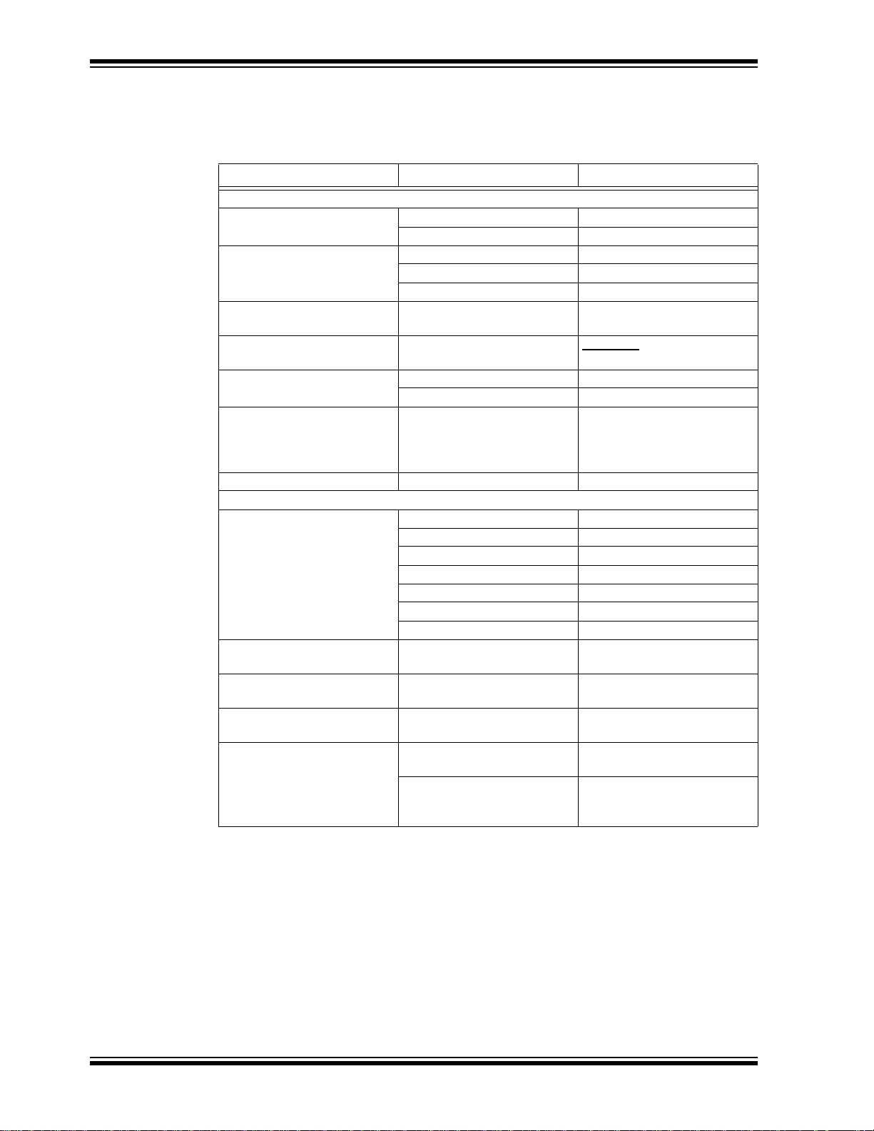
CONVENTIONS USED IN THIS GUIDE
This manual uses the following documentation conventions:
DOCUMENTATION CONVENTIONS
Description Represents Examples
Arial font:
Italic characters Referenced books MPLAB® IDE User’s Guide
Emphasized text ...is the only compiler...
Initial caps A window the Output window
A dialog the Settings dialog
A menu selection select Enable Programmer
Quotes A field name in a window or
dialog
Underlined, italic text with
right angle bracket
Bold characters A dialog button Click OK
N‘Rnnnn A number in verilog format,
Text in angle brackets < > A key on the keyboard Press <Enter>, <F1>
Courier New font:
Plain Courier New Sample source code #define START
Italic Courier New A variable argument file.o, where file can be
Square brackets [ ] Optional arguments mcc18 [options] file
Curly brackets and pipe
character: { | }
Ellipses... Replaces repeated text var_name [,
A menu path File>Save
A tab Click the Power tab
where N is the total number of
digits, R is the radix and n is a
digit.
Filenames autoexec.bat
File paths c:\mcc18\h
Keywords _asm, _endasm, static
Command-line options -Opa+, -Opa-
Bit values 0, 1
Constants 0xFF, ‘A’
Choice of mutually exclusive
arguments; an OR selection
Represents code supplied by
user
“Save project before build”
4‘b0010, 2‘hF1
any valid filename
[options]
errorlevel {0|1}
var_name...]
void main (void)
{ ...
}
DS51565B-page 2 © 2009 Microchip Technology Inc.
Page 7

RECOMMENDED READING
This user's guide describes how to use MCP3905A/06A Energy Meter Reference
Design. Other useful documents are listed below. The following Microchip documents
are available and recommended as supplemental reference resources.
• MCP3905 Data Sheet, “Energy Metering IC with Active Real Power Pulse
Output” (DS21948)
This data sheet provides detailed information regarding the MCP3905A device.
• AN994 Application Note “IEC Compliant Active Energy Meter Design Using
The MCP3905A/06A” (DS00994)
This application note documents the design decisions associated with this reference
design.
THE MICROCHIP WEB SITE
Microchip provides online support via our web site at www.microchip.com. This web
site is used as a means to make files and information easily available to customers.
Accessible by using your favorite Internet browser , the web site contains the following
information:
• Product Support – Data sheets and errata, application notes and sample
programs, design resources, user’s guides and hardware support documents,
latest software releases and archived software
• General Technical Support – Frequently Asked Questions (FAQs), technical
support requests, online discussion groups, Microchip consultant program
member listing
• Business of Microchip – Product selector and ordering guides, latest Microchip
press releases, listing of seminars and events, listings of Microchip sales offices,
distributors and factory representatives
Preface
CUSTOMER SUPPORT
Users of Microchip products can receive assistance through several channels:
• Distributor or Representative
• Local Sales Office
• Field Application Engineer (FAE)
• Technical Support
Customers should contact their distributor, representative or field application engineer
(FAE) for support. Lo cal sales offices are also available to help customers. A listing of
sales offices and locations is included in the back of this document.
Technical support is available through the web site at: http://support.microchip.com
© 2009 Microchip Technology Inc. DS51565B-page 3
Page 8

MCP3905A/06A Energy Meter Reference Design
DOCUMENT REVISION HISTORY
Revision B (August 2009)
• Update from MCP3905/06 to MCP3905A/06A devices
Revision A (July 2005)
• Initial Release of this Document
DS51565B-page 4 © 2009 Microchip Technology Inc.
Page 9

MCP3905A/06A ENERGY METER
REFERENCE DESIGN
Chapter 1. Product Overview
1.1 INTRODUCTION
This chapter provides an overview of the MCP3905A/06A Energy Meter Reference
Design and covers the following topics:
• What is the MCP3905A/06A Energy Meter Reference Design?
• What the MCP3905A/06A Energy Meter Reference Design Kit includes
1.2 WHAT IS THE MCP3905A/06A ENERGY METER REFERENCE DESIGN
The MCP3905A/06A Energy Meter Reference Design device is an energy metering IC
that supplies average active power information via a pulse output with direct drive for
mechanical counters. It also includes a higher-frequency output that supplies
instantanous power information for calibration. The device contains function blocks
specific for IEC energy meter compliance, such as a no-load threshhold and startup
current.
The MCP3905A/06A Energy Meter Reference Design Printed Circuit Board (PCB) is
used as a reference design for single-phase, residential meter s. T he M CP3905 A/0 6A
Energy Meter Reference Design kit includes all necessary PCB circuits and layout tips
for IEC62053 and prior 1036/61036/687 active-energy meter standards compliance.
For more information regarding IEC compliance, refer to AN994, “IEC Compliant Active
Energy Meter Design Using The MCP3905A/06A Energy Meter Reference Design”
(DS00994).
1.3 WHAT THE MCP3905A/06A ENERGY METER REFERENCE DESIGN KIT
INCLUDES:
This MCP3905A/06A Energy Meter Reference Design kit includes:
• MCP3905A/06A Energy Meter Reference Design, 102-00037
• Important Information Sheet
© 2009 Microchip Technology Inc. DS51565B-page 5
Page 10

MCP3905A/06A Energy Meter Reference Design
NOTES:
DS51565B-page 6 © 2009 Microchip Technology Inc.
Page 11

Chapter 2. Installation and Operation
8
9
0
1
8
9
0
1
8
9
0
1
4
5
6
7
8
9
0
1
2
3
4
5
2
3
4
5
current-sensing
element
current-sensing
element
CLASS 1 METER 5(40)a
POWER = 1432 KW
ENERGY = 43213 kWh
28/03/2004
15:23:23
Analog
Digital
PICmicro
®
REFERENCE DESIGN
MCP3905A Stand-Alone Mechanical Counter
Energy Meter
Microcontroller-based LCD Energy Meter
1000 imp/kWh
CLASS 1 METER
5(40)a
MCU
MCP3905A/06A
MCP3905A/06A
MCP3905A/06A
2.1 INTRODUCTION
The MCP3905A/06A Energy Meter Reference Design is a stand-alone, single-phase
residential meter design for active-energy meter designs. For advanced
microcontroller-based meter products, this design also serves as the de sign of the
Analog Front-End (AFE). This design includes a low-cost DC power supply circuit and
the necessary protection for IEC62053 EMC compliance.
MCP3905A/06A ENERGY METER
REFERENCE DESIGN
2.2 FEATURES
FIGURE 2-1: MCP3905A Stand-Alone Energy Meter and Microcontroller-Based Energy Meter Using MCP3905A AFE Design.
For more detailed information regarding design decisions and an approach to
IEC62053 compliance using the circuitry in this board, refer to AN994 “IEC Compliant
Active Energy Meter Design Using The MCP3905A/06A” (DS00994).
The MCP3905A/06A Energy Meter Reference Design PCB has the following features:
• Protection for IEC62053 Energy Meter EMC Immunity Tests
• On-Board DC power supply
• Resistor divider circuit for single-point meter calibration
• Connections for current-sensing shunt or other current sensing element
• Connection for voltage-sensing and power supply biasing
• Connections for mechanical counter and calibration output
• Low-noise PCB layout for small-signal conversion and IEC62053 accuracy
compliance for small shunt values
• Low-cost design
© 2009 Microchip Technology Inc. DS51565B-page 7
Page 12

MCP3905A/06A Energy Meter Reference Design
2.3 GETTING STARTED
This meter can be manufactured by performing the following two steps detailed in this
document. For the external connections, the following terms are used: “phase” refers
to the hot (or line) side of the power supply lines. “Neutral” refers to the return wire
(or low-side) of the power supply lines.
2.3.1 External Connections
Connections are made to the phase and neutral wire for voltag e-detection and AC/DC
power supply . The MCP3905A/06A Energy Me ter Reference De sign is designed to be
biased to the phase (or hot) side of a 2-wire power supply system.
1. Connect JP4 to the phase power supply line connection.
2. Connect JP3 to the neutral line.
3. Connect JP1 and JP2 across the shunt.
4. Connect JP5 and JP6 to the mechanical counter.
2.3.2 Calibration of the Frequency Output using the Voltage Divider
Calibration Circuit
Each meter must be calibrated using the voltag e divider circuit going into Channel 1 of
the MCP3905A/06A. A known power is supplied to the meter (e.g., 1000W), and an
expected output frequency is the goal (1000 imp/kWh). Start with the highest value
resistor and short the resistor using it's respective shorting jumper. If the output
frequency is too high, remove the shunt. Continue testing each resistor short until all
jumpers are tested once. For more det ailed information regarding meter calibra tion and
the PCB design approach using the circuitry in this docume nt , ref er to AN99 4,
“IEC Compliant Active Energy Meter Design Using The MCP3905A/06A” (DS00994).
FIGURE 2-2: Photograph of Complete, Stand-Alone MCP3905A Energy Meter.
DS51565B-page 8 © 2009 Microchip Technology Inc.
Page 13

Installation and Operation
2.4 ENERGY METER REFERENCE DESIGN OVERVIEW
This reference design can be used as eit her a stand-a lone mechanical cou nter energy
meter, or as the analog front-end design in advanced microcontroller-base d meter
designs.
The AFE design limits the overall meter accuracy. A low noise, proven AFE circuit and
layout is still required for a high-accuracy meter. For both meter types, the current
sense input, voltage sense input, calibration scheme, jumper selection and power
supply design blocks described here should apply.
This reference design keeps all of the major compo nents on the back-side of the PCB.
This minimizes any ill effects from the environment in the situation that a meter case
experiences failure. Only the necessary components for calibration, jumper selection
and external connections are placed on the fro nt-side of the board. Keeping the lar ger
DC power supply components on the back-side of the board is also necessary for
installation in some meter cases with PCB standoffs.
The major components on the front-side of the MCP3905A/06A Energy Meter Reference Design are listed here and described in Section 2.5 “Front-Side Of PCB
Detailed Description”.
1. Shunts for Gain, FC and HPF selection (J11-J15).
2. Calibration jumpers (J1-J10).
3. Output connections for mechanical counter and calibration (JP5-JP7).
4. Input connection from the current-sensing element (JP1,JP2).
5. Input connection from voltage or phase line and ground reference point
(JP3,JP4).
6. The analog ground plane, power supply ground plane, moat.
The major components on the back-side of the MCP3905A/06A Energy Meter
Reference Design are listed here and described in Section 2.6 “Back Side Of PCB
Detailed Description”.
1. MCP3905A (U1).
2. DC Power Supply (C17, C16, U2, C18, etc.).
3. Metal Oxide Varistor (MOV1).
4. Optical isolator for PIC
These blocks, and their functionality, will be briefly described in the following two
sections. For more detailed information re garding design decisions and appr oaches to
IEC1036 compliance, refer to AN994, “IEC Compliant Active Energy Meter Design
Using The MCP3905A/06A” (DS00994). For a more detailed circui t schematic, refer to
Appendix A. “Schematics and Layouts” and Appendix B. “Bill Of Materials
(BOM)”.
®
Microcontroller Unit (MCU) or calibration (U3).
© 2009 Microchip Technology Inc. DS51565B-page 9
Page 14

MCP3905A/06A Energy Meter Reference Design
FRONT
Power Supply
Ground Plane
Analog
Ground Plane
BACK
DC Power
Supply
(U1)
Opto.
Isolator (U3)
MOV1
Power Supply
Ground Plane
Analog
Ground Plane
Voltage Conn.
(JP3,JP4)
Current Conn.
(JP1,JP2)
Calibration
Jumpers (J1-J10)
Shunts for Gain,
FC and HPF
Selection (J11-J15)
Output Connections (JP5-JP7)
MCP3905A
FIGURE 2-3: MCP3905A/06A Energy Meter Reference Des i gn Block Dia gr am .
2.5 FRONT-SIDE OF PCB DETAILED DESCRIPTION
2.5.1 Shunts for Gain and FC Selection (J11-J15)
Positions for both logic-high and logic-low are here for all gain and frequen cy const ant
selections. The logic-high positions are labeled “J1H” and the logic-low positions are
labeled “J1L” (Jumper 1 used here as an example). Do n ot short both the high and the
low positions for any one jumper.
2.5.2 Calibration Jumpers (J1-J10)
Calibration resistors for each of these jumper locations are located directly beneath the
associated jumper. When a shorting resistor or jumper is in place, the associated
calibration resistor is shorted and bypassed.
2.5.3 Output Connections for Mechanical Counter and Calibration
JP5 and JP6 are the differential output drive for the mechan ica l c ounter.
(JP5-JP7)
JP7 is the calibration or microcontroller output that is connected to HF
MCP3905A/06A devices. A LED is supplied to assist in any optical calibration
schemes.
2.5.4 Connection to Current-Sensing Element (JP1,JP2)
These two connections lead directly through LRC filtering into Channel 0 of the
MCP3905A/06A. The schematic in Appendix A uses a low-cost shunt as the
current-sensing element. The shunt resistance should be placed in parallel with these
two connections, between JP1 and JP2.
OUT
on the
DS51565B-page 10 © 2009 Microchip Technology Inc.
Page 15

Installation and Operation
2.5.5 Connection to Voltage or Phase Line and Ground Reference
Point (JP3,JP4)
These two connections feed the DC power supply circuitry described in
Section 2.6.3 “Metal Oxide Varistor (MOV1)”. JP4 is connected to the ground of the
PCB, and JP3 to the high-side of the DC power supply circuitry. JP3 is also connected
to the resistor divider that feeds the analog input of Cha nnel 1 o f the MCP39 05A/06A.
This is the channel for measuring voltage and is conne cted to the dif ferential input in a
single-ended fashion. See Appendix A. “Schematics and Layouts” for further det ail.
2.6 BACK SIDE OF PCB DETAILED DESCRIPTION
2.6.1 MCP3905A (U1)
From the back side of the board, the MCP3905A/06A is located on the right ha nd side
where the analog ground plane exists. The MCP390 5 A/0 6A ha s ap pr o pr iate bypass
capacitors on V
its input logic pins connected to user-sel ectable jumpers, with the exception of the HPF
pin. For this system, the HPF is turned on with this pin connected to V
in AC mode only. The NEG connection is not connected in this reference design; this
pin should be left floating. The other three output pins (F
connected to nodes JP5, JP6 and JP7 described later in this section.
coming from the DC power supply circuitry . The MCP3905A/06A has
DD
OUT0
, F
OUT1
; the device is
DD
, HF
OUT
) are
2.6.2 DC Power Supply (C17, C16, U2, C18, D2)
The DC power supply is created from a half-wave zener diode limited AC sig nal feeding
a 7805 +5V regulator . C1 7 and C16 divide the AC sig nal coming directly from the line
and designed in this document for 220V. The zener diode D2 limits the peak voltage to
15V.
2.6.3 Metal Oxide Varistor (MOV1)
A MOV is included to suppress any high voltage transients co ming thro ug h the power
lines.
2.6.4 Optical Isolator (U3)
An optical isolator is included in the reference design as an additional level of protection
for other circuitry used in advanced meter designs (PICmicro
otherwise). It is connected to the HF
Depending on the meter design, it may not be required. This design is a direct-connect
meter that has the entire PCB referenced to the phase or line -side of the power supply.
Therefore, any other circuitry would either need to be biased to the same point or
isolated using this scheme. A pull-up resistor is required on the output of the optical
isolator to allow the HF logic signal to appear.
frequency output of the MCP3905A.
OUT
®
microcontroller, DSP or
2.6.5 The Analog Ground Plane, Power Supply Ground Plane, Moat.
The MCP3905A/06A Energy Meter Reference Design PCB is designed for low-noise
performance and immunity to external influences, as required by IEC61036. The DC
power supply and digital outputs are connected to the power supply ground plane
(right-side of the board when looking at it from the front). The lower noise analog
ground plane, including the MCP3905A/06A connections, is on the o pposite side of the
board, separated by a moat between the two ground planes. An inductive choke
connects the two grounds.
© 2009 Microchip Technology Inc. DS51565B-page 11
Page 16

MCP3905A/06A Energy Meter Reference Design
NOTES:
DS51565B-page 12 © 2009 Microchip Technology Inc.
Page 17

MCP3905A/06A ENERGY METER
Top Layer
Bottom Layer
Appendix A. Schematics and Layouts
A.1 INTRODUCTION
This appendix contains the following schematics and layouts for the MCP3905A/06A
Energy Meter Reference Design:
• Board Schematic
• Board – Top Layer
• Board – Bottom Layer
A.2 SCHEMATICS AND PCB LAYOUT
The layer order is shown in Figure A-1.
FIGURE A-1: LAYER ORDER
REFERENCE DESIGN
© 2009 Microchip Technology Inc. DS51565B-page 13
Page 18

MCP3905A/06A Energy Meter Reference Design
1 2 3 4 56
A
B
C
D
6
54321
D
C
B
A
Title
Number RevisionSize
B
Date: 17-Jun-2005 Sheet of
File: C:\Active Board Files\102-00031 thru 102-00040\102-00037\PCB Files\Protel Files\0003
Drawn By:
C13
10uF/6.3V
C11
220uF/6.3V
C12
0.1uF
C1
0.033uF
C2
0.033uF
C3
0.033uF
C4
0.033uF
C17
0.47uF
C16
0.01uF
C6
0.1uF
C15
0.1uF
C14
0.1uF
C9 22pF
C8 22pF
C7
0.1uF
C18
470uF/35V
C5
10uF/6.3V
D3
1N4744A
D2
1N4004
VOUT
1
VIN
8
G1
2
G4
7
G2
3
G3
6
U2
7805
Z2
110 Ohms at 100MHz
Z3
300ma/150ohmsZ4300ma/150ohms
R22 10 Ohms
R20
20 Ohms
R19
20 Ohms
R1
1K
R2
1K
R3
1K
R4
1K
R16
330K
R15
330K
C10
0.1uF
VDD
JP1
JP2
R21
470 Ohms
MOV1
140-J
JP4
JP3
VDD
CAL-LOWCAL-HIGH
R23
1K
J12L
0 Ohms
J11L
0 Ohms
J12H
0 Ohms
J11H
0 Ohms
J13L
0 Ohms
J14L
0 Ohms
J14H 0 Ohms
J13H 0 Ohms
J15L
0 Ohms
J15H 0 Ohms
R17
1K
Y1
3.579545MHZ
R18
820 Ohms
+ -
D1
RED LED
4
3
1
2
U3
PS2501
VDD
JP7
JP8
JP5
JP6
J1
0 Ohms
J2
0 Ohms
J3
0 Ohms
R5
300K
R6
150K
R7
75K
J4
0 OhmsR839K
J5
0 OhmsR918K
J6
0 Ohms
R10
9.1K
J7
0 Ohms
R11
5.1K
J8
0 Ohms
R12
2.2K
J9
0 Ohms
R13
1.2K
J10
0 Ohms
R14
560 Ohms
CAL-HIGH
CAL-LOW
CALIBRATION NETWORK
To Calibration Network
Z1
110 Ohms at 100MHz
MCP3905 Energy Meter Reference Design
2
103-00037
DVDD1HPF2AVDD3NC14CH0+5CH0-6CH1-7CH1+8MCLR9REFIN/OUT10AGND11F2
12
F113F0
14
G115G0
16
OSC217OSC1
18
NC2
19
NEG
20
DGND
21
HFOUT
22
FOUT123FOUT0
24
U1
MCP3905-SSOP24
REV
REV History Date
1
Initial Release
10/21/05
A.3 BOARD SCHEMATIC
DS51565B-page 14 © 2009 Microchip Technology Inc.
Page 19

A.4 BOARD LAYOUT – TOP LAYER
A.5 BOARD LAYOUT – BOTTOM LAYER
Schematics and Layouts
© 2009 Microchip Technology Inc. DS51565B-page 15
Page 20

MCP3905A/06A Energy Meter Reference Design
NOTES:
DS51565B-page 16 © 2009 Microchip Technology Inc.
Page 21

MCP3905A/06A ENERGY METER
REFERENCE DESIGN
Appendix B. Bill Of Materials (BOM)
TABLE B-1: BILL OF MATERIALS (BOM)
Qty Reference Description Manufacturer Part Number
4 C1, C2, C3, C4 CAP 33000PF 50V CERM X7R 0805 Panasonic® - ECG ECJ-2VB1H333K
2 C5, C13 CAPACITOR TANT 10UF 6.3V 20%
SMD
6 C6, C7, C10,
C12, C14,C15
2 C8, C9 CAP 22PF 50V CERAMIC 0402 SMD Panasonic - ECG ECJ-0EC1H220J
1 C11 CAP 220UF 10V ELECT FC RADIAL Panasonic - ECG EEU-FC1A221S
1 C16 01UF INTERFERFENCE METAL CAP Panasonic - ECG ECQ-U2A103MN
1 C17 47UF/630VDC METAL POLY CAP Panasonic - ECG ECQ-E6474KF
1 C18 CAP 470UF 35V ELECT FC RADIAL Panasonic - ECG EEU-FC1V471
1 D1 LED GREEN DIFFUSED ROUND
1 D2 RECTIFIER GPP 400V 1A DO-41 Diodes Inc. 1N4004-T
1 D3 DIODE ZENER 15V 1W 5% DO-41 Diodes Inc. 1N4744A-T
10 J1-J10 RES .1 OHM 1/4W 5% 1210 SMD Panasonic - ECG ERJ-14RSJR10U
5 J11H, J12H,
J13H, J14H,
J15H
5 J11L, J12L,
J13L, J14L,
J15L
8 JP1--JP8 PIN RECPT .032/.046 DIA 0328 SER Mill-Max
1 MOV1 Suppressors;Clamping Voltage
1 PCB RoHS Compliant Bare PCB,
5 R1-R4, R23 RES 1.00K OHM 1/8W 1% 1206 SMD Panasonic - ECG ERJ-8ENF1001V
1 R5 RES 300K OHM 1/2W 5% 2010 SMD Panasonic - ECG ERJ-12ZYJ304U
1 R6 RES 150K OHM 1/4W 5% 1210 SMD Panasonic - ECG ERJ-14YJ154U
1 R7 RES 75K OHM 1/4W 5% 1206 SMD Panasonic - ECG ERJ-8GEYJ753V
1 R8 RES 39K OHM 1/16W 5% 0402 SMD Panasonic - ECG ERJ-2GEJ393X
1 R9 RES 18K OHM 1/16W 5% 0402 SMD Panasonic - ECG ERJ-2GEJ183X
1 R10 RES 9.1K OHM 1/16W 5% 0402 SMD Panasonic - ECG ERJ-2GEJ912X
1 R11 RES 5.1K OHM 1/16W 5% 0402 SMD Panasonic - ECG ERJ-2GEJ512X
1 R12 RES 2.2K OHM 1/16W 5% 0402 SMD Panasonic - ECG ERJ-2GEJ222X
1 R13 RES 1.2K OHM 1/16W 5% 0402 SMD Panasonic - ECG ERJ-2GEJ122X
Note 1: The components listed in this Bill of Materials are rep resent ative of the PCB assembl y. The released BOM
used in manufacturing uses all RoHS-compliant components.
CAP .1UF 16V CERAMIC X7R 0805 Panasonic - ECG ECJ-2VB1C104K
LONG
RES 0.0 OHM 1/8W 5% 0805 SMD Panasonic - ECG ERJ-6GEY0R00V
Do Not Populate — —
Maximum:710V
MCP3905A/06A Energy Meter Reference Design
®
Kemet
Corp.
Panasonic - SSG LN31GPH
Manufacturing Corp.
EPCOS SIOV-S20K275
— 104-00037
Electronics
®
T491A106M006AS
0328-0-15-15-34-27-10-0
© 2009 Microchip Technology Inc. DS51565B-page 17
Page 22

MCP3905A/06A Energy Meter Reference Design
TABLE B-1: BILL OF MATERIALS (BOM) (CONTINUED)
Qty Reference Description Manufacturer Part Number
1 R14 RES 560 OHM 1/16W 5% 0402 SMD Panasonic - ECG ERJ-2GEJ561X
2 R15, R16 RES 330K OHM 1/2W 5% 2010 SMD Panasonic - ECG ERJ-12ZYJ334U
1 R18 RES 820 OHM 1/4W 5% 1206 SMD Panasonic - ECG ERJ-8GEYJ821V
2 R19, R20 RES 20 OHM 1/4W 5% 1206 SMD Panasonic - ECG ERJ-8GEYJ200V
1 R21 RES 470 OHM 1W 5% METAL OXIDE Panasonic - ECG ERG-1SJ471
1 R22 RES 10 OHM 1/4W 5% 1206 SMD Panasonic - ECG ERJ-8GEYJ100V
1 U1 Energy Metering Device Microchip Technology
Inc.
1 U2 IC VOLT REG 5V 100MA 8-SOIC National
Semiconductor
1 U3 1 CHANNEL OPTO COUPLER
TRANS DIP
1 Y1 CRYSTAL 3.579545MHZ 17PF
HC49/US
2 Z1, Z2 BEAD CORE SINGLE 3.5X9MM
AXIAL
2 Z3, Z4 FERRITE 300MA 150 OHM 1806 SMD Steward
Note 1: The components listed in this Bill of Materials are rep resent ative of the PCB assembly. The released BOM
used in manufacturing uses all RoHS-compliant components.
NEC PS2501-1
ECS Inc ECS-35-17-4
Panasonic - ECG EXC-ELSA39
®
®
Inc. LI1806C151R-10
MCP3905A-I/SS
LM78L05ACM
DS51565B-page 18 © 2009 Microchip Technology Inc.
Page 23

NOTES:
Bill Of Materials (BOM)
© 2009 Microchip Technology Inc. DS51565B-page 19
Page 24

WORLDWIDE SALES AND SERVICE
AMERICAS
Corporate Office
2355 West Chandler Blvd.
Chandler, AZ 85224-6199
Tel: 480-792-7200
Fax: 480-792-7277
Technical Support:
http://support.microchip.com
Web Address:
www.microchip.com
Atlanta
Duluth, GA
Tel: 678-957-9614
Fax: 678-957-1455
Boston
Westborough, MA
Tel: 774-760-0087
Fax: 774-760-0088
Chicago
Itasca, IL
Tel: 630-285-0071
Fax: 630-285-0075
Cleveland
Independence, OH
Tel: 216-447-0464
Fax: 216-447-0643
Dallas
Addison, TX
Tel: 972-818-7423
Fax: 972-818-2924
Detroit
Farmington Hills, MI
Tel: 248-538-2250
Fax: 248-538-2260
Kokomo
Kokomo, IN
Tel: 765-864-8360
Fax: 765-864-8387
Los Angeles
Mission Viejo, CA
Tel: 949-462-9523
Fax: 949-462-9608
Santa Clara
Santa Clara, CA
Tel: 408-961-6444
Fax: 408-961-6445
Toronto
Mississauga, Ontario,
Canada
Tel: 905-673-0699
Fax: 905-673-6509
ASIA/PACIFIC
Asia Pacific Office
Suites 3707-14, 37th Floor
Tower 6, The Gateway
Harbour City, Kowloon
Hong Kong
Tel: 852-2401-1200
Fax: 852-2401-3431
Australia - Sydney
Tel: 61-2-9868-6733
Fax: 61-2-9868-6755
China - Beijing
Tel: 86-10-8528-2100
Fax: 86-10-8528-2104
China - Chengdu
Tel: 86-28-8665-5511
Fax: 86-28-8665-7889
China - Hong Kong SAR
Tel: 852-2401-1200
Fax: 852-2401-3431
China - Nanjing
Tel: 86-25-8473-2460
Fax: 86-25-8473-2470
China - Qingdao
Tel: 86-532-8502-7355
Fax: 86-532-8502-7205
China - Shanghai
Tel: 86-21-5407-5533
Fax: 86-21-5407-5066
China - Shenyang
Tel: 86-24-2334-2829
Fax: 86-24-2334-2393
China - Shenzhen
Tel: 86-755-8203-2660
Fax: 86-755-8203-1760
China - Wuhan
Tel: 86-27-5980-5300
Fax: 86-27-5980-5118
China - Xiamen
Tel: 86-592-2388138
Fax: 86-592-2388130
China - Xian
Tel: 86-29-8833-7252
Fax: 86-29-8833-7256
China - Zhuhai
Tel: 86-756-3210040
Fax: 86-756-3210049
ASIA/PACIFIC
India - Bangalore
Tel: 91-80-3090-4444
Fax: 91-80-3090-4080
India - New Delhi
Tel: 91-11-4160-8631
Fax: 91-11-4160-8632
India - Pune
Tel: 91-20-2566-1512
Fax: 91-20-2566-1513
Japan - Yokohama
Tel: 81-45-471- 6166
Fax: 81-45-471-6122
Korea - Daegu
Tel: 82-53-744-4301
Fax: 82-53-744-4302
Korea - Seoul
Tel: 82-2-554-7200
Fax: 82-2-558-5932 or
82-2-558-5934
Malaysia - Kuala Lumpur
Tel: 60-3-6201-9857
Fax: 60-3-6201-9859
Malaysia - Penang
Tel: 60-4-227-8870
Fax: 60-4-227-4068
Philippines - Manila
Tel: 63-2-634-9065
Fax: 63-2-634-9069
Singapore
Tel: 65-6334-8870
Fax: 65-6334-8850
Taiwan - Hsin Chu
Tel: 886-3-6578-300
Fax: 886-3-6578-370
Taiwan - Kaohsiung
Tel: 886-7-536-4818
Fax: 886-7-536-4803
Taiwan - Taipei
Tel: 886-2-2500-6610
Fax: 886-2-2508-0102
Thailand - Bangkok
Tel: 66-2-694-1351
Fax: 66-2-694-1350
EUROPE
Austria - Wels
Tel: 43-7242-2244-39
Fax: 43-7242-2244-393
Denmark - Copenhagen
Tel: 45-4450-2828
Fax: 45-4485-2829
France - Paris
Tel: 33-1-69-53-63-20
Fax: 33-1-69-30-90-79
Germany - Munich
Tel: 49-89-627-144-0
Fax: 49-89-627-144-44
Italy - Milan
Tel: 39-0331-742611
Fax: 39-0331-466781
Netherlands - Drunen
Tel: 31-416-690399
Fax: 31-416-690340
Spain - Madrid
Tel: 34-91-708-08-90
Fax: 34-91-708-08-91
UK - Wokingham
Tel: 44-118-921-5869
Fax: 44-118-921-5820
03/26/09
DS51565B-page 20 © 2009 Microchip Technology Inc.
 Loading...