

Page 1

MCP2221
I2C Demonstration Board
User’s Guide
2016 Microchip Technology Inc. DS50002480A
Page 2

Note the following details of the code protection feature on Microchip devices:
YSTEM
CERTIFIED BY DNV
== ISO/TS 16949 ==
• Microchip products meet the specification contained in their particular Microchip Data Sheet.
• Microchip believes that its family of products is one of the most secure families of its kind on the market today, when used in the
intended manner and under normal conditions.
• There are dishonest and possibly illegal methods used to breach the code protection feature. All of these methods, to our
knowledge, require using the Microchip products in a manner outside the operating specifications contained in Microchip’s Data
Sheets. Most likely, the person doing so is engaged in theft of intellectual property.
• Microchip is willing to work with the customer who is concerned about the integrity of their code.
• Neither Microchip nor any other semiconductor manufacturer can guarantee the security of their code. Code protection does not
mean that we are guaranteeing the product as “unbreakable.”
Code protection is constantly evolving. We at Microchip are committed to continuously improving the code protection features of our
products. Attempts to break Microchip’s code protection feature may be a violation of the Digital Millennium Copyright Act. If such acts
allow unauthorized access to your software or other copyrighted work, you may have a right to sue for relief under that Act.
Information contained in this publication regarding device
applications and the like is provided only for your convenience
and may be superseded by updates. It is your responsibility to
ensure that your application meets with your specifications.
MICROCHIP MAKES NO REPRESENTATIONS OR
WARRANTIES OF ANY KIND WHETHER EXPRESS OR
IMPLIED, WRITTEN OR ORAL, STATUTORY OR
OTHERWISE, RELATED TO THE INFORMATION,
INCLUDING BUT NOT LIMITED TO ITS CONDITION,
QUALITY, PERFORMANCE, MERCHANTABILITY OR
FITNESS FOR PURPOSE. Microchip disclaims all liability
arising from this information and its use. Use of Microchip
devices in life support and/or safety applications is entirely at
the buyer’s risk, and the buyer agrees to defend, indemnify and
hold harmless Microchip from any and all damages, claims,
suits, or expenses resulting from such use. No licenses are
conveyed, implicitly or otherwise, under any Microchip
intellectual property rights unless otherwise stated.
Microchip received ISO/TS-16949:2009 certification for its worldwide
headquarters, design and wafer fabrication facilities in Chandler and
Tempe, Arizona; Gresham, Oregon and design centers in California
and India. The Company’s quality system processes and procedures
are for its PIC
devices, Serial EEPROMs, microperipherals, nonvolatile memory and
analog products. In addition, Microchip’s quality system for the design
and manufacture of development systems is ISO 9001:2000 certified.
®
MCUs and dsPIC® DSCs, KEEL
®
OQ
code hopping
QUALITY MANAGEMENT S
Trademarks
The Microchip name and logo, the Microchip logo, AnyRate,
dsPIC, FlashFlex, flexPWR, Heldo, JukeBlox, KeeLoq,
KeeLoq logo, Kleer, LANCheck, LINK MD, MediaLB, MOST,
MOST logo, MPLAB, OptoLyzer, PIC, PICSTART, PIC32 logo,
RightTouch, SpyNIC, SST, SST Logo, SuperFlash and UNI/O
are registered trademarks of Microchip Technology
Incorporated in the U.S.A. and other countries.
ClockWorks, The Embedded Control Solutions Company,
ETHERSYNCH, Hyper Speed Control, HyperLight Load,
IntelliMOS, mTouch, Precision Edge, and QUIET-WIRE are
registered trademarks of Microchip Technology Incorporated
in the U.S.A.
Analog-for-the-Digital Age, Any Capacitor, AnyIn, AnyOut,
BodyCom, chipKIT, chipKIT logo, CodeGuard, dsPICDEM,
dsPICDEM.net, Dynamic Average Matching, DAM, ECAN,
EtherGREEN, In-Circuit Serial Programming, ICSP, Inter-Chip
Connectivity, JitterBlocker, KleerNet, KleerNet logo, MiWi,
motorBench, MPASM, MPF, MPLAB Certified logo, MPLIB,
MPLINK, MultiTRAK, NetDetach, Omniscient Code
Generation, PICDEM, PICDEM.net, PICkit, PICtail,
PureSilicon, RightTouch logo, REAL ICE, Ripple Blocker,
Serial Quad I/O, SQI, SuperSwitcher, SuperSwitcher II, Total
Endurance, TSHARC, USBCheck, VariSense, ViewSpan,
WiperLock, Wireless DNA, and ZENA are trademarks of
Microchip Technology Incorporated in the U.S.A. and other
countries.
SQTP is a service mark of Microchip Technology Incorporated
in the U.S.A.
Silicon Storage Technology is a registered trademark of
Microchip Technology Inc. in other countries.
GestIC is a registered trademarks of Microchip Technology
Germany II GmbH & Co. KG, a subsidiary of Microchip
Technology Inc., in other countries.
All other trademarks mentioned herein are property of their
respective companies.
© 2016, Microchip Technology Incorporated, Printed in the
U.S.A., All Rights Reserved.
ISBN: 978-1-5224-0492-7
DS50002480A-page 2 2016 Microchip Technology Inc.
Page 3

Object of Declaration: MCP2221 I2C Demonstration Board User’s Guide
2016 Microchip Technology Inc. DS50002480A-page 3
Page 4

MCP2221 I2C Demonstration Board User’s Guide
NOTES:
DS50002480A-page 4 2016 Microchip Technology Inc.
Page 5

MCP2221 I2C DEMONSTRATION
BOARD USER’S GUIDE
Table of Contents
Preface ...........................................................................................................................7
Introduction............................................................................................................ 7
Document Layout .................................................................................................. 7
Conventions Used in this Guide ............................................................................ 8
Recommended Reading........................................................................................ 9
The Microchip Web Site ........................................................................................ 9
Customer Support ................................................................................................. 9
Document Revision History ................................................................................... 9
Chapter 1. Product Overview
1.1 Introduction ................................................................................................... 11
1.2 MCP2221 I
1.3 What the MCP2221 I
2
C Demonstration Board Description ......................................... 11
2
C Demonstration Board Kit Includes ......................... 13
Chapter 2. Installation and Operation
2.1 Minimum System Requirements .................................................................. 15
2.2 Board Setup ................................................................................................. 15
2.3 Jumpers and Connectors Description .......................................................... 16
2.4 Test Points Description ................................................................................ 18
Chapter 3. Testing Board Features
3.1 About the MPC2221 I2C Demo Board Application ....................................... 19
3.2 General Information Panel Description ........................................................ 20
3.3 Feature Tabs ................................................................................................ 21
Chapter 4. Creating Custom I2C Software Applications
4.1 USB to I2C .................................................................................................... 39
4.2 PIC16F1509 as I
2
4.3 I
C Slave Addresses .................................................................................... 41
2
C Master .......................................................................... 40
Chapter 5. Troubleshooting
5.1 Board Not Detected by PC ........................................................................... 43
5.2 USB Driver Installation Issues ...................................................................... 43
5.3 PC Application Reports “MCP2221 Not Connected” .................................... 43
5.4 PC Application Reports I
5.5 Issues Programming the PIC
2
C Errors ............................................................... 44
®
Microcontroller ............................................. 44
2016 Microchip Technology Inc. DS50002480A-page 5
Page 6

MCP2221 I2C Demonstration Board User’s Guide
Appendix A. Schematics and Layouts
A.1 Introduction .................................................................................................. 45
A.2 Board – Interface Schematic ........................................................................ 46
A.3 Board – Slaves Schematic ........................................................................... 47
A.4 Board – Top Silk .......................................................................................... 48
A.5 Board – Top Copper and Silk ....................................................................... 48
A.6 Board – Top Copper .................................................................................... 49
A.7 Board – Bottom Copper ............................................................................... 49
A.8 Board – Bottom Copper and Silk ................................................................. 50
A.9 Board – Bottom Silk ..................................................................................... 50
Appendix B. Bill of Materials (BOM)...........................................................................51
Worldwide Sales and Service .....................................................................................54
DS50002480A-page 6 2016 Microchip Technology Inc.
Page 7

MCP2221 I2C DEMONSTRATION
BOARD USER’S GUIDE
Preface
NOTICE TO CUSTOMERS
All documentation becomes dated, and this manual is no exception. Microchip tools and
documentation are constantly evolving to meet customer needs, so some actual dialogs
and/or tool descriptions may differ from those in this document. Please refer to our web site
(www.microchip.com) to obtain the latest documentation available.
Documents are identified with a “DS” number. This number is located on the bottom of each
page, in front of the page number. The numbering convention for the DS number is
“DSXXXXXXXXA”, where “XXXXXXXX” is the document number and “A” is the revision level
of the document.
For the most up-to-date information on development tools, see the MPLAB
Select the Help menu, and then Topics to open a list of available online help files.
®
IDE online help.
INTRODUCTION
This chapter contains general information that will be useful to know before using the
MCP2221 I
• Document Layout
• Conventions Used in this Guide
• Recommended Reading
• The Microchip Web Site
• Customer Support
• Document Revision History
DOCUMENT LAYOUT
This document describes how to use the MCP2221 I2C Demonstration Board as an
evaluation tool to debug a target motor system. The manual layout is as follows:
• Chapter 1. “Product Overview” – Important information on the board.
• Chapter 2. “Installation and Operation” – Covers the initial setup of this board
and the Graphical User Interface (GUI).
• Chapter 3. “Testing Board Features” – Describes how to use the board’s
capabilities.
• Chapter 4. “Creating Custom I
information for the custom usage of the board.
• Chapter 5. “Troubleshooting”– Provides procedures for troubleshooting the
most common problems encountered when installing and operating the board.
• Appendix A. “Schematics and Layouts” – Shows the schematic and layout
diagrams for the board.
• Appendix B. “Bill of Materials (BOM)” – Lists the parts used to build the board.
2
C Demonstration Board. Items discussed in this chapter include:
2
C Software Applications”– Provides
2016 Microchip Technology Inc. DS50002480A-page 7
Page 8

MCP2221 I2C Demonstration Board User’s Guide
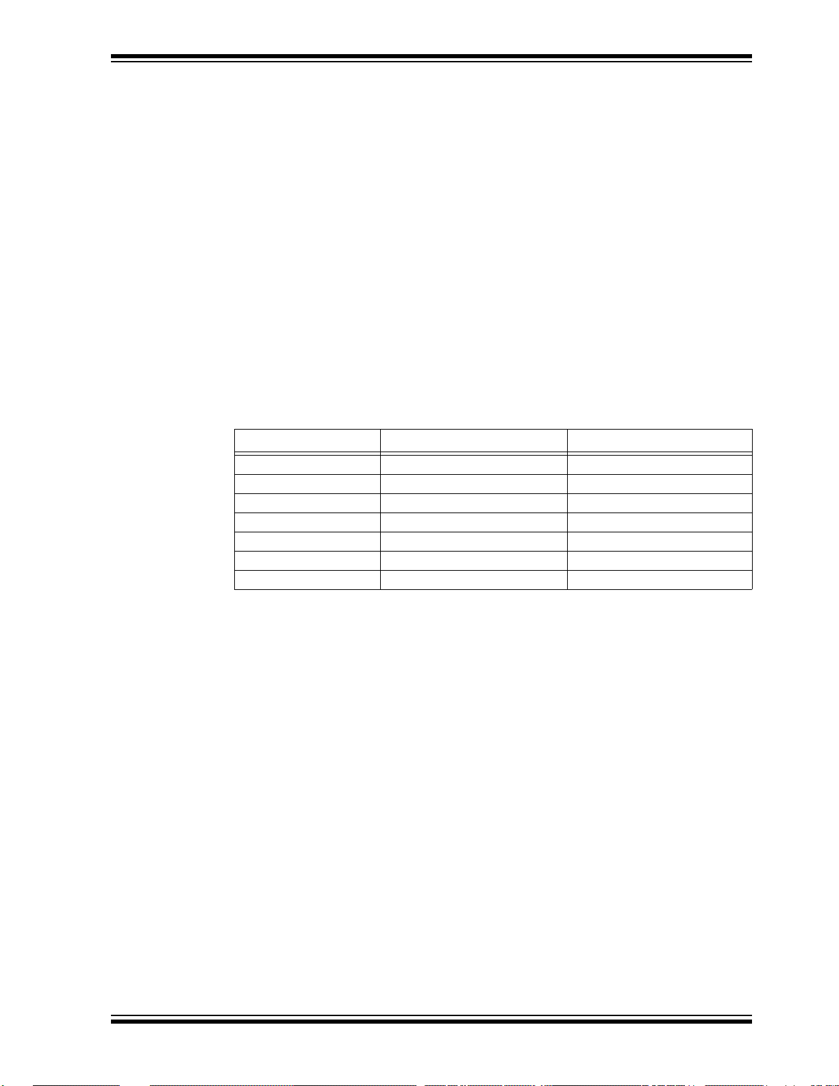
CONVENTIONS USED IN THIS GUIDE
This manual uses the following documentation conventions:
DOCUMENTATION CONVENTIONS
Description Represents Examples
Arial font:
Italic characters Referenced books MPLAB
Emphasized text ...is the only compiler...
Initial caps A window the Output window
A dialog the Settings dialog
A menu selection select Enable Programmer
Quotes A field name in a window or
dialog
Underlined, italic text with
right angle bracket
Bold characters A dialog button Click OK
N‘Rnnnn A number in verilog format,
Text in angle brackets < > A key on the keyboard Press <Enter>, <F1>
Courier New font:
Plain Courier New Sample source code #define START
Italic Courier New A variable argument file.o, where file can be
Square brackets [ ] Optional arguments mcc18 [options] file
Curly brackets and pipe
character: { | }
Ellipses... Replaces repeated text var_name [,
A menu path File>Save
A tab Click the Power tab
where N is the total number of
digits, R is the radix and n is a
digit.
Filenames autoexec.bat
File paths c:\mcc18\h
Keywords _asm, _endasm, static
Command-line options -Opa+, -Opa-
Bit values 0, 1
Constants 0xFF, ‘A’
Choice of mutually exclusive
arguments; an OR selection
Represents code supplied by
user
“Save project before build”
4‘b0010, 2‘hF1
any valid filename
[options]
errorlevel {0|1}
var_name...]
void main (void)
{ ...
}
®
IDE User’s Guide
DS50002480A-page 8 2016 Microchip Technology Inc.
Page 9

RECOMMENDED READING
This user’s guide describes how to use the MCP2221 I2C Demonstration Board. Other
useful documents are listed below. The following Microchip documents are available
and recommended as a supplemental reference resource.
• MCP2221 Data Sheet – “USB 2.0 to I
(DS20005292)
• PAC1710/20 Data Sheet – “Single and Dual Hig h-Side Curr ent-Sense Monitor
with Power Calculation” (DS20005386)
• MCP3221 Data Sheet – “Low-Power 12-Bit A/D Converter With I
(DS21732)
• MCP9808 Data Sheet – “±0.5°C Maximum Accuracy Digital Temperature Sensor”
(DS25095)
• PIC16(L)F1508/9 Data Sheet – “20-Pin Flash, 8-Bit Microcontrollers with XLP
Technology” (DS40001609)
• MCP4706/4716/4726 Data Sheet – “8-/10-/12-Bit Voltage Output
Digital-to-Analog Converter with EEPROM and I
• MCP23008/MCP23S08 Data Sheet – “8-Bit I/O Expander with Serial Interface”
(DS21919)
Preface
2
C™/UART/Protocol Converter with GPIO”
2
C™ Interface”
2
C™ Interface” (DS22272)
THE MICROCHIP WEB SITE
Microchip provides online support via our web site at www.microchip.com. This web site
is used as a means to make files and information easily available to customers. Accessible
by using your favorite Internet browser, the web site contains the following information:
• Product Support – Data sheets and errata, application notes and sample
programs, design resources, user’s guides and hardware support documents,
latest software releases and archived software
• General Technical Support – Frequently Asked Questions (FAQs), technical
support requests, online discussion groups, Microchip consultant program
member listing
• Business of Microchip – Product selector and ordering guides, latest Microchip
press releases, listing of seminars and events, listings of Microchip sales offices,
distributors and factory representatives
CUSTOMER SUPPORT
Users of Microchip products can receive assistance through several channels:
• Distributor or Representative
• Local Sales Office
• Field Application Engineer (FAE)
• Technical Support
Customers should contact their distributor, representative or field application engineer
(FAE) for support. Local sales offices are also available to help customers. A listing of
sales offices and locations is included in the back of this document.
Technical support is available through the web site at:
http://www.microchip.com/support.
DOCUMENT REVISION HISTORY
Revision A (April 2016)
• Initial release of this document.
2016 Microchip Technology Inc. DS50002480A-page 9
Page 10

MCP2221 I2C Demonstration Board User’s Guide
NOTES:
DS50002480A-page 10 2016 Microchip Technology Inc.
Page 11

MCP2221 I2C DEMONSTRATION
BOARD USER’S GUIDE
Chapter 1. Product Overview
1.1 INTRODUCTION
This chapter provides an overview of the MCP2221 I2C Demonstration Board and
covers the following topics:
• MCP2221 I
• What the MCP2221 I
1.2 MCP2221 I2C DEMONSTRATION BOARD DESCRIPTION
2
C Demonstration Board Description
2
C Demonstration Board Kit Includes
The MCP2221 I2C Demonstration Board allows the user to communicate through a PC
application to I
converter (bridge). Additionally, it can create a USB to RS-232 (UART) bridge using the
same MCP2221 board.
2
C slave devices by using the MCP2221 device as a USB to I2C master
1.2.1 Board Features Controlled through PC Application
Here are the main features of the demonstration board when used with its dedicated
PC application:
• Users can perform measurements for resistors (above 10Ω) or capacitors (above
40 nF), using the MCP2221 device’s Analog-to-Digital Converter (ADC) and
General Purpose Input/Output (GPIO) pins
• Real-time monitoring and logging of the current, and power consumptions of a
USB device using the PAC1710 current, voltage and power sensor
• Real-time monitoring and logging of the ambient temperature using the MCP9808
temperature sensor
• Real-time monitoring and logging of the voltage level recorded by the MCP3221
device’s 12-bit ADC
• Configuration and control of up to 8 GPIOs, available from the MCP23008 I/O
expander, as well as continuously monitoring the state of the pins (when used as
digital inputs)
• PIC16F1509 configuration to issue multiple warnings through an RGB LED when
any of the featured readings are outside of user settable conditions (such as
“measured USB current is above 50 mA”)
• Storing the above mentioned configuration, as well as other random data, in a
24LC128 128-Kbit Electrically Erasable Programmable Read-Only Memory
(EEPROM)
• Output voltage level control of the MCP4726 Digital-to-Analog Converter (DAC)
• Creating a USB to RS-232 bridge, based on the MCP2221 device and a Texas
Instrument’s MAX3232 transceiver; alternately creating a USB to UART bridge to
the PIC16F1509 microcontroller
2016 Microchip Technology Inc. DS50002480A-page 11
Page 12

MCP2221 I2C Demonstration Board User’s Guide
1.2.2 Other Hardware Features
The board also provides features that are independent of the software application:
• 5V or 3.3V user-selectable V
demonstration board and all on-board devices.
2
•I
C female socket (similar to the PICkit™ Serial Analyzer) for connectivity to external slaves, as well as test points for the I
disconnect the on-board, 4.7 k
• In-Circuit Serial Programming™ (ICSP™) male connector to debug or program
the PIC16F1509 using a PICkit 3 programmer or another compatible tool.
• The option to connect the PIC16F1509 device’s Universal Asynchronous
Receiver/Transmitter (UART) to the board’s RS-232 connector (through the
MAX3232 transceiver).
• A small prototyping area which includes extensions of the board’s power (V
and ground (GND) lines.
• Test points to measure the current, voltage or power of non-USB devices (as well
as receive configurable interrupts) using the PAC1710 current-sensing chip.
• Option to connect the interrupt pin of the MCP23008 I/O expander to an external
interrupt pin of the PIC16F1509 for custom applications.
1.2.3 I2C Devices Available on the Board
, up to 500 mA operating capability for the
DD
2
C lines, and the option to
pull-up resistors for the I2C data and clock lines.
DD
)
Ta bl e 1 -1 identifies the I2C devices (master and slaves) available on the MCP2221 I2C
Demonstration Board.
TABLE 1-1: I
Device
Name
MCP2221 Master USB to I
PAC1710 Slave Single High-Side Current Sense Monitor with Power Calculation
24LC128 Slave 128-Kbit EEPROM
MCP9808 Slave Temperature Sensor
MCP3221 Slave 1-Channel, 12-Bit Analog-to-Digital Converter (ADC)
MCP4726 Slave 12-Bit Digital-to-Analog Converter (DAC)
MCP23008 Slave 8-Bit I/O Expander
PIC16F1509 Slave 8-Bit Microcontroller (preprogrammed to perform as I
2
C DEVICES AVAILABLE ON THE MCP2221 BOARD
I2C
Master/Slave
2
C/UART/SMBus Protocol Converter with GPIO
(Master Mode)
Description
2
C slave)
DS50002480A-page 12 2016 Microchip Technology Inc.
Page 13

Figure 1-1 illustrates the components on the top view.
MCP2221
PIC16F1509
PAC 1710
24LC128
MCP9808
MCP3221
MCP4726
MCP23008
FIGURE 1-1: MCP2221 TOP VIEW – I
2
C DEVICES ON THE BOARD
1.3 WHAT THE MCP2221 I2C DEMONSTRATION BOARD KIT INCLUDES
The MCP2221 I2C Demonstration Board Kit (ADM00678) includes:
2
• MCP2221 I
• Preprogrammed PIC16F1509 Microcontroller
• Two Mini-USB Cables
• Important Information Sheet
C Demonstration Board
2016 Microchip Technology Inc. DS50002480A-page 13
Page 14

MCP2221 I2C Demonstration Board User’s Guide
NOTES:
DS50002480A-page 14 2016 Microchip Technology Inc.
Page 15

MCP2221 I2C DEMONSTRATION
Chapter 2. Installation and Operation
2.1 MINIMUM SYSTEM REQUIREMENTS
BOARD USER’S GUIDE
The MCP2221 I2C Demonstration Board is designed to be used in a Microsoft®
Windows
(client profile). Users can utilize the Microsoft.NET Framework 4 web installer package
to download and install the Microsoft.NET Framework 4 components.
For USB connectivity, the minimal physical requirement for the PC is a standard
USB 2.0 port. The board connects to the PC via the mini-USB connector (J4). In case
the board connects to the PC through a USB hub, use a self-powered hub.
2.2 BOARD SETUP
Before the MCP2221 I2C Demonstration Board can be used, a few steps must be
performed to install the PC software and configure the board’s hardware.
2.2.1 Software Installation
Follow these steps to install the required software:
1. Download the support material (PC application) that can be found on the board’s
page at www.microchip.com.
2. Unzip the archive and install the .exe file. The setup process should also
perform the USB driver installation, if needed. If there are driver-related issues,
refer to Section 5.2 “USB Driver Installation Issues”.
2.2.2 Hardware Setup
Follow these steps to set up the hardware:
1. Check if the board is properly powered from USB by setting jumper J19 to either
5V or 3.3V; by default, it is set to 5V.
2. Connect the MCP2221 I
port (J4).
®
XP (SP3 or later) environment, based on the Microsoft.NET Framework 4
2
C Demonstration Board to a PC through the mini-USB
2016 Microchip Technology Inc. DS50002480A-page 15
Page 16

DS50002480A-page 16 2016 Microchip Technology Inc.
Legend:
1 = Enable potentiometer R13 for MCP3221 ADC 6 = Enable LEDs, LD2-LD9, for MCP23008 GPIO expander
2 = Enable board’s I
2
C pull-up resistors, R10 and R11 7 = Enable SDA (data) line of PIC16F1509 for I2C connectivity
3 = Connect UART RX of PIC16F1509 to UART TX of MCP2221 8 = Enable SCL (clock) line of PIC16F1509 for I
2
C connectivity
4 = Connect UART RX of MCP2221 to UART TX of PIC16F1509 9 = Enable RGB LED (connect to PIC16F1509)
5 = Set board voltage (V
DD
) to 5V
1
2
3
4
5
6
7
8
9
MCP2221 I
2.3 JUMPERS AND CONNECTORS DESCRIPTION
Refer to Figure 2-1 to view the default settings for the jumpers and connectors.
FIGURE 2-1: DEFAULT JUMPERS AND CONNECTORS CONFIGURATIONS
2
C Demonstration Board User’s Guid e
Page 17

Installation and Operation
Ta bl e 2 -1 describes the functions of all the board’s jumpers and connectors.
TABLE 2-1: MCP2221 BOARD JUMPERS CONFIGURATION
Jumper
Designator
J1 PDIP socket for PIC16F1509 microcontroller.
J2 Female connector to the MCP4726 Digital-to-Analog Converter; one pin is the DAC output and the
other connects to the ground.
J3 Male connector to the MCP4726 Digital-to-Analog Converter; one pin is the DAC output and the other
connects to the ground.
J4 Mini-B type USB female connector for power and connectivity for MCP2221 from the PC.
J5 RS-232 female connector.
2
J6 Jumper connecting the I
connected by default.
J7 Female connector to the MCP3221 Analog-to-Digital Converter; one pin is the ADC custom input and
the other connects to the ground; for custom input, disconnect jumper J18.
J8 Male connector to the MCP3221 Analog-to-Digital Converter; one pin is the ADC custom input and the
other connects to the ground; for custom input, disconnect jumper J18.
J9 Jumper connecting the I
connected by default.
J10 Female connector for the MCP9808 temperature sensor. One pin connects to the sensor’s ALERT
and the other to the ground.
J11 Male connector for the MCP9808 temperature sensor. One pin connects to the sensor’s ALERT pin and
the other to the ground.
J12 Jumper for configuring the UART/RS-232 traffic directions:
• MCP2221 to PIC16F1509: Short-circuit (RX MCU) with (TX USB), then (TX MCU) with (RX USB).
This is the default setting.
• MCP2221 to RS232
• PIC16F1509 to RS232:
J13 Female connector for measuring resistances and capacitances. The ‘–’ (minus) sign indicates the
ground pin in case of measuring polarized capacitors.
J14 Jumper enabling the RGB LED LD1 that connects to the PIC16F1509. The jumper is connected by
default.
J15 Jumper allowing the possibility to connect the interrupt pin of the MCP23008 I/O expander to pin RA2 of
the PIC16F1509. The jumper is not connected by default (not populated).
J16 Female connector to the eight I/O pins of the MCP23008 I/O expander. When using the connector,
consider disabling the LEDs connected to the I/O pins by removing jumper J20.
J17 Male connector to the eight I/O pins of the MCP23008 I/O expander. When using the connector,
consider disabling the LEDs connected to the I/O pins by removing jumper J20.
J18 Jumper connecting the potentiometer R13 to the ADC input pin of the MCP3221 DAC. Disconnect
jumper to allow custom voltage measurements via connectors J7/J8. The jumper is connected by
default.
J19 Jumper for selecting the voltage level (V
3.3V or middle and right hand side pins for 5V. The default setting is for 5V.
J20 Jumper enabling LEDs LD2-LD9 that are connected to the I/O pins of the MCP23008 I/O expander;
consider removing it if using connectors J16 and J17. The jumper is connected by default.
J21 Mini-B type USB female connector used for measuring current, voltage and power with the PAC1710.
This side goes towards the USB voltage source, such as a PC.
J22 A type USB female connector used for measuring current/voltage/power with the PAC1710. Connect
the USB device (load) through this jumper.
J23 In-Circuit Serial Programming™ (ICSP™) connector for the PIC16F1509, compatible with the
PICkit™ 3 debugger/programmer; the white triangle indicates the first pin (MCLR
C SDA (data) pin of the PIC16F1509 to the board’s SDA line. This jumper is
2
C SCL (clock) pin of the PIC16F1509 to the board’s SCL line. This jumper is
: Short-circuit (RX RS-232) with (RX USB), then (TX RS-232) with (TX USB).
Short-circuit (RX RS-232) with (RX MCU), then (TX RS-232) with (TX MCU).
Function Description
) of the board: connect left hand side and middle pins for
DD
/VPP).
pin
2016 Microchip Technology Inc. DS50002480A-page 17
Page 18

MCP2221 I2C Demonstration Board User’s Guide
TABLE 2-1: MCP2221 BOARD JUMPERS CONFIGURATION (CONTINUED)
Jumper
Designator
Function Description
J24 Jumper enabling the 4.7 pull-up resistors for the I2C data (SDA) and clock (SCL) lines on the board.
Consider removing it if the demonstration board connects to an external I
2
has I
C pull-up resistors. The jumper is connected by default.
J25 I2C female connector; similar to the PICkit™ Serial Analyzer connector; however, this one only has the
power and I
not connected.
2
C lines (VDD, GND, SDA, SCL). The white triangle indicates the first pin. Pins 1 and 6 are
2
C slave circuit which already
2.4 TEST POINTS DESCRIPTION
Ta bl e 2 -2 describes the board’s test points.
TABLE 2-2: MCP2221 BOARD TEST POINTS CONFIGURATION
T est Point
Designator
TP1 Test point for measuring resistance or capacitance. If required, connect the positive pin of the polarized
capacitor to this test point.
TP2 Test point (connected to ground) for measuring resistance or capacitance. If required, connect the
negative pin of the polarized capacitor to this test point.
TP3 Test point for the ALERT
application.
TP4 Test point for the load side (target USB device) of the PAC1710 measuring circuit.
TP5 Test point for the source side (USB Host/PC) of the PAC1710 measuring circuit.
TP6 Test point for the I2C SDA line of the board.
TP7 Test point for the I2C SCL line of the board.
TP8 Test point connected to ground.
pin of the PAC1710. This test point is not used by the demonstration board’s
Description
DS50002480A-page 18 2016 Microchip Technology Inc.
Page 19

MCP2221 I2C DEMONSTRATION
Setup Area
General Information Panel
Feature Tabs
BOARD USER’S GUIDE
Chapter 3. Testing Board Features
This section describes the working principles and limitations that should be taken into
account when using the board with the dedicated PC application, as well as the actual
steps to use all of the demonstration kit’s features.
It is assumed that the user has already successfully run the installation process
described in Section 2.2 “Board Setup”.
3.1 ABOUT THE MPC2221 I2C DEMO BOARD APPLICATION
The PC application for the device is named the MCP2221 I2C Demo Board Application.
The three main sections that can be observed in Figure 3-1 are the Feature tabs,
General Information panel and Setup area.
FIGURE 3-1: THE MCP2221 I
2
C DEMO BOARD APPLICATION – INITIAL VIEW
2016 Microchip Technology Inc. DS50002480A-page 19
Page 20

MCP2221 I2C Demonstration Board User’s Guide
For more information on the General Information panel, see Section 3.2 “General
Information Panel Description”.
The Feature tabs determine the content of the Setup area. For more information, see
Section 3.3 “Feature Tabs”.
3.2 GENERAL INFORMATION PANEL DESCRIP T ION
3.2.1 The Device Status Label
The Device status label displays whether the board is connected to the PC. One of the
following messages is generated by the system:
• MCP2221 Connected
• MCP2221 not Connected
3.2.2 The Using Custom VID/PID... Button
When clicking the Using Custom VID/PID... button, the Select VID & PID window is
displayed. The window contains information on the VID/PID combination to find the
drivers that are to be used for the USB device.
FIGURE 3-2: THE SELECT VID & PID WINDOW
By default, the values are 0x4D8 for the VID and 0xDD for the PID. New values can be
inserted in the “Look for VID (Hexadecimal Form)” and the “Look for PID (Hexadecimal
Form)” fields. After inserting the new values, click the Update Settings button. Users
can return to the default values by clicking the Use Default Values button.
3.2.3 The I2C Communication Status Box
By default, the “I2C Communication Status” text box is blank. It is populated when
actions are performed in the Feature tabs. The information is system-generated and
read-only.
Message examples include: “EEPROM write successful”, “Pins states updated”,
“Settings saved” and others. If errors are displayed, see Section 5.4 “PC Application
Reports I
2C Errors”
.
3.2.4 The Clear I2C Status Box Button
Click the Clear I2C Status Box button to clear the I2C Communication Status box.
Note that clearing the text in the box does not cancel or revert any previously performed
action.
DS50002480A-page 20 2016 Microchip Technology Inc.
Page 21
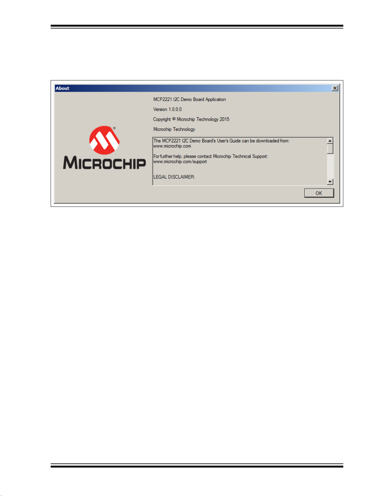
3.2.5 The About Button
Click the About button to open a window that contains information on the application’s
version and legal disclaimers. Click the OK button to close the window.
FIGURE 3-3: THE ABOUT WINDOW
Testing Board Features
3.3 FEATURE TABS
The left panel of the application contains nine tabs that allow the user to explore all the
board’s features:
• Measure R, C
• Measure USB Power
• Measure Temperature
• Read/Write EEPROM
• Read ADC
• Configure DAC
• GPIO Expander
• RGB LED Notifications
• UART Communication
Each tab displays a dedicated setting area when selected.
3.3.1 Measure R, C Tab
Capacitance is determined by measuring the capacitor’s charging time. In case of large
capacitors, the charging time is software limited to 10 seconds, after which, a
mathematical formula is applied to determine the approximate capacitance. The
charging current is provided by a digital output pin of the MCP2221 board and limited
by a 470 kΩ resistor. The Measure R, C tab also generates a charging graph for the
capacitor, as well as an indicator of its voltage.
Resistance is determined by placing the unknown resistor in series with another known
one, thus creating a voltage divider where relative voltage values are sufficient to
calculate the resistance.
Prior to performing measurements, the pins must be correctly placed in the connector
marked with J13 or use the test points, TP1 and TP2.
2016 Microchip Technology Inc. DS50002480A-page 21
Page 22

MCP2221 I2C Demonstration Board User’s Guide
3.3.1.1 TAB OPERATION
To measure a resistor or capacitor, select the Measure R, C tab.
• Click the Measure Resistance button to measure the resistance. The system
displays the approximate resistance and a capacitor charging graph.
• Click the Measure Capacitance button to measure capacitance. The system
displays the approximate capacitance and a capacitor charging graph.
Note: In case of a polarized capacitor, make sure the pins are correctly placed –
the ‘+’ (plus) and ‘–’ (minus) signs on the board must be next to connectors,
J13 and TP2.
Figure 3-4 shows an example of measuring resistance.
FIGURE 3-4: MEASURING RESISTANCE
3.3.1.2 CONSIDERATIONS AND WARNINGS
• The minimum supported values are around 10Ω for resistors and 40 nF for capacitors.
• To maintain a certain level of accuracy, the maximum recommended values to
measure are ~1 MΩ for resistors and 470
µ
F for capacitors.
• The measurement accuracy may be, in some cases, of about ±10%, therefore the
MCP2221 I
2
C Demonstration Board Kit is not recommended for precision
measurements.
• For both capacitor and resistance measurements, voltages are generated by
digital output pins and measured using the analog input pins of the MCP2221 I
2
C
Demonstration Board.
DS50002480A-page 22 2016 Microchip Technology Inc.
Page 23

Testing Board Features
3.3.2 Measure USB Power Tab
The Measure USB Power tab allows users to perform current, voltage or power
measurements of a USB device.
Prior to measuring the current/power of the USB device, make sure that:
• The load to be measured (for example a USB mouse) is connected to the
MCP2221 board’s USB socket marked with J22
• The power source (such as the PC) is connected to the mini-USB socket marked
with J21
3.3.2.1 TAB OPERATION
Users can determine what measurements the system should perform by selecting at
least one of the following check boxes: “Chart Voltage”, “Chart Current” or “Chart
Power”.
The “Show Numbers” check box determines whether numerical values for voltage,
current and power will also be indicated in real time inside its corresponding text box.
If the check box is selected, current and power will be indicated in real time.
Generated data can be saved using the “Log into .CSV File …” check box. When the
check box is selected, the Open window opens to allow users to select the .csv file or
create a new document, where the measured data can be logged. Figure 3-5 depicts
this action.
FIGURE 3-5: SELECTING A .csv FILE
It is advisable to use comma separated values for the.csv file type to be Microsoft
®
Excel
compatible.The .csv file is generated by the application, with four columns,
and each set of readings is placed on a row. The columns are: Data entry index,
Voltage (in Volts), Current (in Amps), Power (in Watts). Logging can be turned off by
clearing the check box.
®
2016 Microchip Technology Inc. DS50002480A-page 23
Page 24

MCP2221 I2C Demonstration Board User’s Guide
Click the Start Measurement button for the system to start performing measurements.
Pressing the Stop Measurement button interrupts the measurements.The Reset
Measurement button clears all the previously generated data and prepares the system
for new measurements.
The Measure All One Time button is for the application to retrieve, in real time, just
one set of numeric values (for voltage, current and power) and to write them in the corresponding text box below it. This can be used as an alternate solution to
Start Measurement in order to save system resources.
Figure 3-6 shows an example for measuring the current, voltage and power of a USB
Flash drive when connected to the PC via the measuring circuit.
FIGURE 3-6: MEASURING CURRENT, VOLTAGE AND POWER OF A USB DEVICE
DS50002480A-page 24 2016 Microchip Technology Inc.
Page 25

Testing Board Features
3.3.2.2 WARNINGS AND CONSIDERATIONS
• When measuring the current/power consumption, it is recommended to connect
the loads (devices) that do not draw a current above ~2.5A.
• A shunt resistor of 0.025Ω is used, which sets the PAC1710 chip’s full-scale cur-
rent value to 3.2A. However, current limitations are also imposed by the MCP2221
board’s design.
• In case of continuous measurement, samples are taken once every 100 milliseconds,
so higher frequency variations may not be noticed by the application.
• The software provides the option not to display specific variations (such as populating the voltage graph, for example) to reduce the amount of tasks that the PC
must perform. This is especially useful when the PC is running low on system
resources (like processor usage or memory filling).
• Even when switching to a different tab (such as measuring resistors), if the
monitoring is enabled, then it will not be automatically halted unless the board is
physically disconnected from the PC. Therefore, it is recommended to stop
performing the measurements when they are no longer required.
3.3.2.3 NOTIFICATIONS FUNCTIONALITY
The MCP2221 board also provides three access points (TP3, TP4 and TP5), described
in Section 2.3 “Jumpers and Connectors Description”.
The PAC1710 chip can be configured to signal notifications via the ALERT
connected to the TP3 test point of the MCP2221 I
For custom measurements, it’s highly recommended to read the data sheet for the
PAC1710 chip, as well as view the schematic and layouts of the board, available in
Appendix A. “Schematics and Layouts” of this document.
2
C Demonstration Board.
pin that’s
3.3.3 Measure Temperature Tab
The temperature sensor is built into the MCP9808 chip. The sensor’s accuracy
depends on the temperature value intervals, as seen in the following table:
Temperature Value Intervals Accuracy
-40°C to +125°C ±0.25° (typical)
-20°C to +100°C ±0.5°C (maximum)
-40°C to +125°C ±1°C (maximum)
In the case of continuous monitoring, samples are taken once every 100 milliseconds,
so higher frequency variations may not be noticed by the software.
The software provides the option not to display specific variations (for example, populating the temperature graph) to reduce the amount of tasks that the PC must perform.
This is especially useful when the PC is running low on system resources (such as
processor usage or memory filling).
Even when switching to a different application tab, if the monitoring is enabled, then it
will not be automatically halted unless the board is physically disconnected from the
PC. Therefore, it is recommended to stop performing the measurements when they are
no longer required.
2016 Microchip Technology Inc. DS50002480A-page 25
Page 26

MCP2221 I2C Demonstration Board User’s Guide
3.3.3.1 TAB OPERATION
The Measure Temperature tab allows users to perform temperature measurements.
The “Show in Chart” check box determines if a graph is displayed during the real-time
measurements. Users can choose the measuring unit (Fahrenheit or Celsius) inside
the “Unit” radio button group.
The functionalities of the “Show Numbers” and the “Log into .CSV File...” check boxes
are similar to the ones described in Sec tion 3.3.2 “Measure USB Power Tab”.
However, the .csv file contains two columns and each set of readings is placed on a
row. The columns are: Data entry index and Temperature.
The functionalities of the Start Measurement, Stop Measurement and Reset
Measurement buttons are similar to the ones described in Section 3.3.2 “Measure
USB Power Tab”.
Click the Measure Temperature Once button for the application to retrieve, in real
time, just one set of numeric values (for temperature) and to write them in the
corresponding text box below it. This can be used as an alternate solution to Measure
Temperature, in order to save system resources.
For example, the application can be set so that temperatures exceeding 26°C will result
in an orange LED blinking on the board. Custom LED notifications are described in
Section 3.3.8 “RGB LED Notifications Tab”.
Figure 3-7 shows an example for measuring the temperature in °C.
FIGURE 3-7: TEMPERATURE MEASUREMENT
DS50002480A-page 26 2016 Microchip Technology Inc.
Page 27

Testing Board Features
3.3.3.2 NOTIFICATIONS FUNCTIONALITY
The MCP9808 temperature sensor can be configured to output an alert signal when the
temperature changes beyond the specified boundary limits. The signal can be read on
the MCP2221 board through the pin extensions marked with J10 and J11. More
information is available in Section 2.3 “Jumpers and Connectors Description”.
3.3.4 Read/Write EEPROM Tab
The 24LC128 EEPROM is organized into 256 pages of memory (numbered from 0 to
255), each containing 64 bytes of data. The MCP2221 I
plays the memory content per page, organized in a matrix of 16 rows and 4 columns.
Data and addresses are displayed in hexadecimal form.
The last page of the EEPROM, page 255, is also used to store the LED notifications
configuration that is described in S ection 3.3.8 “RGB LED Notifications Tab”.
By default, all the memory bytes are set as 0xFF.
Writing to a data cell will cause the EEPROM to rewrite the cell’s entire page.
3.3.4.1 TAB OPERATION
Follow these steps to write to a specific cell or page of the EEPROM:
1. Select the Read/Write EEPROM tab.
2. From the “Select Page” drop-down, choose the EEPROM memory page you
want to read or write.
3. The address of the cell can be determined by adding the column and row indexes
in the matrix table below. Edit a cell by double-clicking on it and entering the 8-bit
value in hexadecimal form (example: for 0x1C, write 1C). Users must enter a
valid number in hexadecimal form, between 0x00 and 0xFF.
4. To update the EEPROM content, click the Write Page button. Figure 3-8 shows
an example of writing the 0x1A value to address 0x1D0
Number 7).
2
C Demo Board Application dis-
(Memory Page
2016 Microchip Technology Inc. DS50002480A-page 27
Page 28

MCP2221 I2C Demonstration Board User’s Guide
FIGURE 3-8: WRITING INTO THE EEPROM
To read an EEPROM page:
1. Select the desired page number from the “Select Page” drop-down.
2. Click the Read Page button.
The Erase All EEPROM Data button resets the entire content of the EEPROM to 0xFF.
The Reset Entire T able to 0xFF button only affects the displayed matrix, not the actual
EEPROM memory.
DS50002480A-page 28 2016 Microchip Technology Inc.
Page 29

Testing Board Features
3.3.5 Read ADC Tab
The MCP3221 Analog-to-Digital Converter uses both a fixed 2.5V voltage reference
and the power supply from an MCP1525 voltage reference chip, which allows the
conversion to be independent of the demo board’s power line: 3.3V/5V.
Therefore, the analog voltage to be measured must be between 0 and 2.5V. The board
can be used to measure the voltage from:
• Potentiometer R13, from the 2.5V supply that’s also powering the MCP3221 if
jumper J18 is connected (the default setting);
or
• An external source (via J7 and J8) if jumper J18 is disconnected.
In case of continuous monitoring, samples are taken once per 100 milliseconds, so
higher frequency variations may not be noticed by the PC application.
The software provides the option not to display specific variations (such as populating
the ADC graph) to reduce the amount of tasks that the PC must perform. This is
especially useful when the PC is running low on system resources (such as processor
usage or memory filling). Even when switching to a different application tab, if the
monitoring is enabled, then it will not be automatically halted unless the board is
physically disconnected from the PC. Therefore, it is recommended to stop performing
the measurements when they are no longer required. Prior to performing measurements, make sure to select the analog voltage source by connecting or removing
jumper J18. See Tab le 2 -1 for more information.
3.3.5.1 TAB OPERATION
Select the Read ADC tab to perform ADC measurements.
The “Show in Chart” check box determines whether a chart is generated by the system
to illustrate the measured values.
The functionalities of the “Show numbers” and the “Log into .CSV File...” check boxes
are similar to the ones described in Sec tion 3.3.2 “Measure USB Power Tab”.
However, the .csv file contains two columns and each set of readings is placed on a
row. The columns are: Data entry index, Voltage (in Volts).
The functionalities of the Start Measurement, Stop Measurement and Reset
Measurement buttons are similar to the ones described in Section 3.3.2 “Measure
USB Power Tab”.
The Measure ADC Voltage Once button is for the application to retrieve, in real time,
just one set of numeric values (for voltage) and to write them inside the text box below
it. This can be used as an alternate solution to Start Measurement in order to save
system resources.
Custom LED notifications (for example: voltage readings above 2.31V results in a green
LED blinking on the board) are described in Section 3.3.8 “RGB LED Notifications Tab”.
2016 Microchip Technology Inc. DS50002480A-page 29
Page 30

MCP2221 I2C Demonstration Board User’s Guide
Figure 3-9 shows an example for measuring the voltage:
FIGURE 3-9: VOLTAGE MEASUREMENT
DS50002480A-page 30 2016 Microchip Technology Inc.
Page 31

Testing Board Features
3.3.6 Configure DAC Tab
The MCP4726 DAC (Digital-to-Analog Converter) uses an MCP1525 as a 2.5V voltage
reference, thus allowing it to generate a fixed voltage no matter if the board’s power
(V
) is set to 3.3V or 5V.
DD
The MCP4726 also has the option to set a 2x reference gain, which means that only if
the MCP2221 I
analog voltage output can be as high as 5V. This option can be enabled from the PC
application.
3.3.6.1 TAB OPERATION
Follow these steps to set the voltage value for the DAC:
1. Select the Configure DAC tab.
2. From the Select Reference Voltage radio button group, choose the preferred
voltage. The default value is 2.5V. Note that users should only select 5V if the
V
DD
3. To set the output voltage, use one of the following formats:
- Inside the text box corresponding to the “Write Value in Volts” text box, type
in the numeric value;
or
- Select the “Set Voltage in Real Time” check box, then adjust the slider. The
resulting values will be shown in the text box corresponding to “Write Value
in Volts (Example: 2.35)” label. Use a period (.) and not a comma (,) to write
the value.
4. Regardless of the method used to set the output voltage, the voltages are only
submitted to the board after the user clicks the Set Voltage button. The value is
also displayed below the “Current Voltage” label, inside the corresponding
read-only text box.
5. To read the output voltage value back from the chip’s register, click the Read
V oltage Dat a button. The value is displayed in the read-only text box, below the
“Current Voltage” label.
2
C Demonstration Board works at 5V (jumper J19 is set to 5V), then the
value is 5V.
2016 Microchip Technology Inc. DS50002480A-page 31
Page 32

MCP2221 I2C Demonstration Board User’s Guide
Figure 3-10 shows how to configure the DAC to output 1.45V.
FIGURE 3-10: CONFIGURING THE DIGITAL-TO-ANALOG CONVERTER
3.3.7 Digital I/O Pins Tab
The MCP23008 pin expander provides access to eight configurable digital input/output
pins. Short-circuiting jumper J20 connects LEDs, LD2, LD3,…,LD9, to the eight pins.
The eight general purpose pins are also accessible via connectors J16 and J17. For
example, if a pin is configured as an output and intended to be connected to an external
circuit or component via J16 or J17, it may help to remove jumper J20 in order to
preserve the pin’s current driving strength.
In case a pin is used as a digital input, a logical high input signal should match the
demonstration board’s power level (3.3V or 5V, determined via jumper J19). For more
information on voltage tolerances, see the “MCP23008/MCP 23S 08 Data Sheet”
(DS21919).
Even when switching to a different application tab (such as for measuring resistors), if
the pin state monitoring (auto-read) is enabled, then it will not be automatically halted
unless the board is physically disconnected from the PC. Therefore, it is recommended
to stop performing the readings when they are no longer required.
Custom LED notifications for pin GP0 (for example: the pin having a logical high state
results in a yellow LED blinking on the board) are described in Section 3.3.8 “RGB
LED Notifications Tab”.
DS50002480A-page 32 2016 Microchip Technology Inc.
Page 33

Testing Board Features
3.3.7.1 TAB OPERATION
To control the digital I/O pins, follow these steps:
1. Select the GPIO Expander tab.
2. Configure the pin directions (input or output) under the “Set GPIO Direction”
section. The configuration only becomes active after the user clicks the Submit
Pin Directions button.
3. For the pins that are set as outputs, the “Configure Pin State (if Output)” section
allows the user to change their state in one of the following ways:
- All at once, if the “Instant Command” check box is cleared and when
clicking the Submit Pin States button;
or
- Individually (real-time state toggling), the “Instant Command” check box is
selected.
In case a pin is configured as an input, these pin state control commands are ignored.
Reading the states for all eight general purpose pins can be done by either:
• Automatically (continuously, every 100 milliseconds), in case the “Auto Read
Every 100ms” check box is selected;
or
• Manually, by clicking on the Read Pin States button.
Figure 3-11 shows an example of using the GPIO Expander tab.
FIGURE 3-11: INTERFACING THE GPIO EXPANDER
2016 Microchip Technology Inc. DS50002480A-page 33
Page 34

MCP2221 I2C Demonstration Board User’s Guide
3.3.7.2 UNIMPLEMENTED FEATURES
The MCP23008 also has a separate interrupt output pin which can be used to signal to
2
the I
C master, a logical state change of one of its input pins.
By default, the interrupt pin is not connected to the MCP3221. It can be connected to
the RA2 pin of the PIC16F1509 by short-circuiting jumper J15, in case of a custom
application, where, for example, the PIC16F1509 is programmed to perform as an I
master.
3.3.8 RGB LED Notifications Tab
LED notifications can be configured to indicate certain events related to the readings
described in the previous sections.
The LED can indicate events every 500 milliseconds (including 100 milliseconds of
specific color) allocated per I
• PAC1710 USB voltage, current or power consumption
• MCP9808 temperature sensor
• MCP3221 analog voltage value
• MCP23008 GP0 pin state change
In the remaining 100 milliseconds from one time period, the LED will be powered off.
In case a device does not have notifications enabled for its corresponding time interval,
the LED will also be powered off.
As a general observation, higher frequency events may not be noticed in time to be
signaled by the LED.
Notifications are done using the RGB LED LD1, that is fully controlled by three
Pulse-Width Modulation (PWM) pins of the PIC16F1509, which receives commands
2
(as I
C slave) from the MCP2221 DLL through the MCP2221 board. The LED color and
brightness are configured from the PC application. It is recommended to avoid light
color tones, because they can translate into very intense LED brightness.
Prior to attempting to configure the LED notifications, make sure that:
• The PIC16F1509 microcontroller is present in socket J1 and that it can
communicate via I
2
C (jumpers J6 and J9 must be connected)
• Jumper 14 is connected to enable the RGB LED LD1
2
C device:
2
C
DS50002480A-page 34 2016 Microchip Technology Inc.
Page 35

Testing Board Features
3.3.8.1 TAB OPERATION
Follow these steps to enable a notification:
1. Open the RGB LED Notifications tab.
2. The Preview Color… button brings up the Color window, allowing users to
choose colors.
FIGURE 3-12: COLOR WINDOW
3. After selecting the desired colors, click the OK button and the system changes
the LED color accordingly.
4. To enable a specific notification, select the color you want in the “Blink” radio
button group corresponding to the notification. You can either:
- Select the default color (blue, red, green or white) available for each of the
four notifications;
or
- Set any color by selecting the “custom color...” radio button. In the Color
window (Figure 3-12), choose one of the basic colors or define a new color
and click OK.
5. Set the notification conditions, including the numeric value for comparison, if
applicable.
6. Click the corresponding “Enable” check box.
7. Optional. Users can also click the Save Preferences into EERPROM button to
save the current created configuration inside the 24LC128 EEPROM that’s on
the MCP2221 board (data is stored inside its last memory page, 255). Also, the
Load Preferences from EEPROM button can be used to restore configurations
from the EEPROM.
Note: Changing a numeric value used for the comparison will clear the “Enable”
check box.
2016 Microchip Technology Inc. DS50002480A-page 35
Page 36

MCP2221 I2C Demonstration Board User’s Guide
Figure 3-13 shows how the LED is configured to blink (blue color) in case the measured
USB current exceeds 85 mA.
FIGURE 3-13: CONFIGURING LED NOTIFICATIONS
DS50002480A-page 36 2016 Microchip Technology Inc.
Page 37

Testing Board Features
3.3.9 UART Communication Tab
There are several combinations of connectivity, which are determined through
jumper J12:
• (Default Setting): MCP2221 (from PC) to PIC16F1509. Every time the
®
PIC
microcontroller receives a character from the MCP2221, it increments its
value and sends it back.
• MCP2221 (from PC) to RS-232 connector.
• PIC16F1509 to RS-232. Unless the PIC microcontroller is reprogrammed, it will
behave the same as in Case 1 described above.
For the first two cases, data loss (sent or received) may be noticed inside the PC
application’s text box due to the nature of the .NET Framework that is used by the
application. A work around is to use a third-party PC application for COM port bridging.
3.3.9.1 TAB OPERATION
To receive information on the COM ports present in the system, follow these steps:
1. Open the UART Communication tab.
2. Click the Get COM Ports Info button for the system to display information (in the
text box below it) about the COM ports present in the system; this can be used
to determine the COM port number of the MCP2221 USB to I
from the demonstration board.
3. Select the COM port number from the drop-down box. The system will populate
the “Baud:”, “Data Bits:” and “Stop Bits:” fields. For example, the settings in the
case of communication between MCP2221 and PIC16F1509 (determined
through jumper J12) are: Baud: 9600, Data Bits: 8, Stop Bits: 1.
4. Open the COM port by clicking the Open Port button.
5. Received data is automatically added inside the read-only text box on the
right-hand side as red colored text.
To send data, follow these steps:
1. Open the UART Communication tab.
2. Enter the information you want to communicate in the text boxes corresponding
to the Text 1, Text Line 2 and Text Line 3 buttons, under the “Send data:”
section.
3. “Sent data:” can be seen inside the read-only text box on the right-hand side
(combined with the received data) if the “Show Sent Data” check box is selected.
4. The buttons, Text Line 2 and Text Line 3, place the sent/received data on a new
line inside the text box.
5. To clear the text box, click the Clear Serial Data Box button.
2
C/UART converter
2016 Microchip Technology Inc. DS50002480A-page 37
Page 38

MCP2221 I2C Demonstration Board User’s Guide
Figure 3-14 shows an example of sending the text ‘12’ to the PIC microcontroller and
receiving ‘23’ back.
FIGURE 3-14: UART COMMUNICATION WITH THE PIC16F1509
DS50002480A-page 38 2016 Microchip Technology Inc.
Page 39

MCP2221 I2C DEMONSTRATION
BOARD USER’S GUIDE
Chapter 4. Creating Custom I2C Software Applications
This chapter provides a few suggestions on how to get started in developing custom
applications that involve I
Board.
Section 4.1 “USB to I
Interface (GUI) lies on a USB Host (such as a PC or Android device).
Section 4.2 “PIC16F1509 as I
board (or a pin-compatible PIC
while also using (or not) the MCP2221.
Section 4.3 “I
found on the demonstration board.
4.1 USB TO I2C
This section discusses two aspects of a USB to I2C custom application:
• Interfacing the MCP2221 I
• Connecting external I
4.1.1 Using a Different Operating System or Application
The MCP2221 can be accessed via USB from several types of operating systems:
Windows
are available on the MCP2221 official web site.
Also available for download are several applications that can be used for I
and for GPIO pin configuration, such as the MCP2221 I
Windows or the MCP2221 Terminal Android Application for Android.
In order to create a custom application (GUI), the user can call the MCP2221 associated functions (for its configuration or actual data transfer) through the DLL files that
can be downloaded from the same location.
For Android, the source code for the application and the available libraries can be used
as a basis for developing a new application.
See the “Recommended Reading” section for more information on the I
devices.
2
C communication, using the MCP2221 I2C Demonstration
2
C”: The MCP2221 is the I
2
C Master”: The PIC16F1509 which is available on the
®
microcontroller) is presumed to be the I2C master,
2
C Slave Addresses”: Lists the I
2
C Demonstration Board from a different PC
application, or even, an operating system.
2
C slaves to the MCP2221 I2C Demonstration Board.
®
, Linux®, Mac® or Android. The required USB drivers and related information
2
C master and the Graphical User
2
C slave addresses of the devices
2
2
C/SMBus Terminal for
C transfer
2
C slave
4.1.2 Connecting External I2C Slaves to the Board
The MCP2221 I2C Demonstration Board also provides the possibility to connect
external I
from the PICkit™ Serial Analyzer in terms of I
indicates the first pin of the socket.
2016 Microchip Technology Inc. DS50002480A-page 39
2
C slave devices using the female connector J25. This is same as the one
2
C connectivity. The white colored triangle
Page 40

MCP2221 I2C Demonstration Board User’s Guide
These are the pin designations:
- Pin 1: Not connected
-Pin 2: V
user-selectable (3.3V or 5V via jumper J19)
- Pin 3: GND (ground connection)
- Pin 4: SDA (I
-Pin 5: SCL (I
- Pin 6: Not connected
Additional test points are available in the case, for example, of connecting a logical
analyzer to the demo board’s I
- TP6: Test point connected to the I
- TP7: Test point connected to the I
- TP8: Test point connected to ground
(power) must be provided by the I2C demonstration board and it is
DD
2
C data line)
2
C clock line)
2
C bus:
2
C data line
2
C clock line
Note: If the externally connected I
connected to the I
board can be disconnected by removing jumper J24.
4.2 PIC16F1509 AS I2C MASTER
There may be the case where it is desirable to have the PIC16F1509 microcontroller
as the I
information related to the hardware connectivity (power supply and I
communication), as well as programming the PIC16F1509.
4.2.1 Hardware Connectivity
For powering the board, there are two possibilities:
1. From the PC, via the mini-USB connector J4 (USB Host) or a from a USB charger
2. By connecting an external power supply (between 3.3V and 5V) to the board’s
2
C master with no required USB communication. This section contains
adapter that provides a constant 5V (DC) and at a recommended minimum of
200 mA. In this case, the board’s voltage level can be set to either 3.3V or 5V,
depending on how jumper J19 is connected.
V
power line, ideally through:
DD
• The V
pin that is available on the ICSP™ (In-Circuit Serial Programming™)
DD
connector marked with J23;
or
• The V
pin that is available on the female connector J25.
DD
2
2
C data and clock lines, the ones available on the demo
C slave already has its own pull-up resistors
2
C
Note: In case a power supply is connected directly to the V
line, jumper J19
DD
should be completely disconnected to avoid unwanted current flow. This
flow could affect the board’s MCP1825 voltage regulator or the USB
connector marked with J4.
To enable I
• The PIC16F1509 connects to the I
• The I
2
C communication, make sure that:
2
2
C data and clock lines’ pull-up resistors are connected; if no pull-up
C bus by short-circuiting jumpers J6 and J9.
resistors are externally connected to the board, then jumper J24 must be
connected.
DS50000000A-page 40 2016 Microchip Technology Inc.
Page 41
Creating Custom I2C Software Applications
4.2.2 Programming the PIC16F1509
The PIC16F1509 can be programmed via the ICSP (In-Circuit Serial Programming)
connector marked with J23, with tools such as the PICkit™ 3 or compatible
debuggers/programmers. In case there are programming issues, consult
Chapter 5. “Troubleshooting” in this document.
The source code for the PIC microcontroller can be written using MPLAB
the XC8 C compiler that are available for download at http://www.microchip.com.
Part of the code, including for the I
MPLAB Code Configurator plug-in.
4.3 I2C SLAVE ADDRESSES
This section lists the addresses of the I2C slave devices that are available on the
demonstration board. The values displayed in Ta ble 4 -1 are in the 8-bit form and can
be used directly as parameters during application development when calling the
MCP2221.DLL functions.
The 8-bit equivalent (write address) of a 7-bit I
left-shift-once (or multiplication by 2) of the 7-bit address.
®
X IDE and
2
C master, can be generated automatically using the
2
C address is the result of a
TABLE 4-1: LIST OF I
Device I2C Write 8-Bit Address I2C Read 8-Bit Address
24LC128 0xA0 0xA1
MCP23008 0x40 0x41
MCP3221 0x9A 0x9B
MCP4726 0xC0 0xC1
MCP9808 0x32 0x33
PAC1710 0x5C 0x5D
PIC16F1509 0x10 0x11
2
C SLAVE ADDRESSES
2016 Microchip Technology Inc. DS50000000A-page 41
Page 42

MCP2221 I2C Demonstration Board User’s Guide
NOTES:
DS50000000A-page 42 2016 Microchip Technology Inc.
Page 43

MCP2221 I2C DEMONSTRATION
BOARD USER’S GUIDE
Chapter 5. Troubleshooting
This chapter handles a number of possible scenarios that may occur when the
MCP2221 I
2
C Demonstration Board does not function as expected.
5.1 BOARD NOT DETECTED BY PC
In case the PC does not signal, either visually or acoustically, that the MCP2221 board
has been connected, perform the following actions:
• Check the board’s power selection jumper. Make sure jumper J19 is connected
and that its default position is for 5V operation.
• Connect the PC to the correct on-board mini-USB socket. The board communi-
cates with the PC and it is also powered using the mini-USB connector marked
with J4, not J21.
• Verify that enough power is provided to the board. If the board connects through a
USB hub, then the hub should be self-powered.
5.2 USB DRIVER INSTALLATION ISSUES
When connecting the MCP2221 board to a PC running a Windows® operating system,
the USB driver should install automatically. In case the process is not successful, the
driver can be downloaded from http://www.microchip.com/mcp2221, extracted to a
folder on the local drive and then installed manually, as described below.
1. From the Start menu, select Control Panel>Device Manager
to the PC and see what device is added to the list under Ports.
2. Right-click on the device and click the Update Driver Software… button.
3. Manually select the folder where the driver has been extracted.
4. Click OK.
After the driver installs, a system restart may be required.
. Connect the board
5.3 PC APPLICATION REPORTS “MCP2221 NOT CONNECTED”
When a USB device (such as the MCP2221) connects to the USB Host (such as the
PC), the host will ask for the device’s Product and Vendor IDs (VID & PID).
The default values for the MCP2221 are 0x4D8 and 0xDD. In case any of these values
has been changed by the user, and the USB.inf driver file has been customized
accordingly and has been installed properly, then the PC application will report the
“MCP2221 not connected” error message. In such a case, the application can be
configured to look for a device with custom values by clicking the Using Custom
VID/PID… button.
Note: The MCP2221 I
inside the MCP2221 board. This can be done using the MCP2221 Utility
which can be downloaded from http://www.microchip.com. However, extra
knowledge in terms of legal and technical implications is required.
2016 Microchip Technology Inc. DS50002480A-page 43
2
C Demo Board Application does not rewrite the VID & PID
Page 44

MCP2221 I2C Demonstration Board User’s Guide
5.4 PC APPLICATION REPORTS I2C ERRORS
If the text box corresponding to the I2C Communication Status label indicates an error
followed by a number, then the physical and logical setup of the I
checked. Perform the following verifications:
• Check the pull-up resistors. External I
2
C circuits connected to the MCP2221 I2C
Demonstration Board may have their own pull-up resistors for the I
clock lines, in which case, jumper J24 should be removed depending on the
resulting resistances; otherwise, J24 must be connected.
• Check for slave address conflicts. In case there are external I
to the board, make sure there are no overlapping addresses. The list of addresses
of the devices available on the board is detailed in Section 4.3 “I
Addresses of this document.
• Check the I
2
C error codes. The codes are available inside the “MCP2221
Breakout Module User’s Guide” (DS50002282, package version 06/17/2015)
available at www.microchip.com.
5.5 ISSUES PROGRAMMING THE PIC® MICROCONTROLLER
In case the PICkit™ 3 (or another Microchip debugger/programmer compatible to the
PIC microcontroller) is configured to provide power to the target device, but reports that
PIC16F1509 cannot be programmed, the cause may be that the PICkit 3 cannot
provide enough power to the PIC device.
In such a case, it is recommended to power the MCP2221 board externally through:
• The mini-USB connector marked as J19 (as opposed to powering from the
PICkit 3) from the PC;
or
• A USB charger that provides a constant 5V (DC) at a recommended minimum of
200 mA if the microcontroller supports this voltage level.
2
C bus should be
2
C data and
2
C slaves connected
2
C Slave
DS50002480A-page 44 2016 Microchip Technology Inc.
Page 45

Appendix A. Schematics and Layouts
A.1 INTRODUCTION
MCP2221 I2C DEMONSTRATION
BOARD USER’S GUIDE
This appendix contains the schematics and layouts for the following devices which are
included in the MCP2221 I
• Board – Interface Schematic
• Board – Slaves Schematic
• Board – Top Silk
• Board – Top Copper and Silk
• Board – Top Copper
• Board – Bottom Copper
• Board – Bottom Copper and Silk
• Board – Bottom Silk
2
C Demonstration Board Kit (ADM00678):
2016 Microchip Technology Inc. DS50002480A-page 45
Page 46

DS50002480A-page 46 2016 Microchip Technology Inc.
VDD
1
GP0
2
GP1
3
RST
4
UART RX
5
UART TX
6
GP2
7
GP3
8
SDA
9
SCL
10
VUSB
11
D-
12
D+
13
VSS
14
VDD
GP0GP1RS
UA
U
GP2GP3
SDA
SCL
VUS
D-
D
VSS
U3
MCP2221
ID
4
VBUS
1
GND
5
D-
2
D+
3
0
USB Mini-B
J4
GND
D_N
D_ND_P
D_P
VDD
5V
VUSB
SCL
SDA
GP3
GP0
GP1
RESET
RX_MCP
TX_MCP
GP2
GND
VIN
1
GND
2
VOUT
3
U2
MCP18255V
4.7uF
10V
0603
C15
GNDGND
0.1uF
16V
0603
C16
GND
123
HDR-2.54 Male 1x3
J19
4.7uF
10V
0603
C17
GND
VDD
5V
10k
0603
5%
R2
VDD
SCL SDA
10k
0603
1%
R3
10k
0603
1%
R5
GND
TP LOOP Black
TP1
12
HDR-2.54 Female 1x2
J13
GND
TP LOOP Black
TP2
10k
0603
1%
R4
0.1uF
16V
0603
C14
0.47uF
6.3V
0603
C2
VDD
GND GND
USB connector for MCP2221 Power module I2C Pull-Up R esistors
470k
0603
1%
R6
4.7k
0603
5%
R10
4.7k
0603
5%
R11
12
HDR-2.54 Male 1x2
J24
GND
VDD
1
2
3
4
5
6
HDR-2.54 Female 1x6
J25
SDA
SCL
TP LOOP Black
TP7
TP LOOP Black
TP6
SCL
SDA
TP LOOP Black
TP8
GND
MCP2221 and R/C measurement circuit I2C bus pinouts
1
2
3
4
5
6
7
8
9
DE-9 Female
J5
112
34
56
78
HDR-2.54 Male 2x4
J12
TX_MAX
RX_MAX
RX_MAX TX_MAX
TX_PIC/RB7
TX_MCP
GND
0.1uF
16V
0603
C6
GND
VDD
0.1uF
16V
0603
C4
0.1uF
16V
0603
C5
GND
0.1uF
16V
0603
C1
0.1uF
16V
0603
C3
MAX3232 UART adapter and RS-232 connector
RX_MCP
RX_PIC/RB5
UART connectivity selection jumpers
4
5
6
7
8
9
10
16
15
14
13
12
11
17
1
2
3
19
18
20
J1
VDD
RA5
RA4
MCLR/RA3
RC5
RC4
RC3
RC6
RC7
TX_PIC/RB7
VSS
RA0/ICSPDAT
RA1/ICSPCLK
RA2
RC0
RC1
RC2
RB4
RX_PIC/RB5
RB6
GND
10k
0603
5%
R1
2
1
43
GREEN
RED
BLUE
5
6
CLX6A-FKB-CK1P1G1BB7R3R3
LD1
LED_RGB
GND
12
HDR-2.54 Male 1x2
J14
12
HDR-2.54 Male 1x2
J9
12
HDR-2.54 Male 1x2
J6
SCL
SDA
IO_INT
PIC16F1509 microcontroller
1
2
3
4
5
6
HDR-2.54 Male 1x6
J23
MCLR/RA3
VDD VDD
VSS
RA0/ICSPDAT
RA1/ICSPCLK
RA2
1.5k
0603
5%
R7
3.3k
0603
5%
R8
2.7k
0603
5%
R9
12
HDR-2.54 Male 1x2
J15
ICSP connector
MCP23008 interrupt pin to PIC
VDD
C1+
1
V+
2
C1-
3
C2+
4
C2-
5
V-
6
DOUT2
7
RIN28ROUT2
9
DIN2
10
DIN1
11
ROUT1
12
RIN1
13
DOUT1
14
GND
15
VCC
16
C1+
V+
C1-
C2+
C2-
V-
2
N2
ROUT2
DIN
DIN1
ROU
RIN1
DOU
GND
VCC
MAX3232
U1
VUSB
0.1uF
16V
0603
C21
GND
MCP2221 I
A.2 BOARD – INTERFACE SCHEMATIC
+
T
B
RT RX
ART TX
C Demonstration Board User’s Guid e
2
DOUT
RI
T1
T1
2
Page 47

2016 Microchip Technology Inc. DS50002480A-page 47
SENSE+
1
SENSE-
2
NC1
3
NC2
4
GND
5
ADDR_SEL
6
ALERT#
7
SMDATA
8
SMCLK
9
VDD
10
GND1
11
SENSE+
SENS
C1
G
A
L
A
SMDATA
SMC
V
PAC1710
U6
GND
20k
0603
5%
R21
TP LOOP Black
TP3
0.1uF
16V
0603
C18
GND
VDD
GND
1uF
10V
0603
C19
SCL
SDA
GND
GND
ID
4
VBUS
1
GND
5
D-
2
D+
3
0
USB Mini-B
J21
VBUS
1
GND
4
D-
2
D+
3
VBUS
G
D+
0
USB-A Female
J22
TP LOOP Black
TP5
TP LOOP Black
TP4
GND GND
SENSE_P SENSE_N SENSE_P SENSE_N
PAC1710 USB current and power measurer
0.025R
2512
1%
R17
A0
1
SDA
5
A2
3
A1
2
WP
7
VSS
4
SCL
6
VCC
8
U4
24LC128
0.1uF
16V
0603
C8
GND
SCL
SDA
GND
VDD
24LC128 EEPROM
SDA
1
SCL
2
Alert
3
GND4A2
5
A1
6
A0
7
VDD
8
U5
MCP9808
VDD
GNDGND
SCL
SDA
TMP_ALERT
GND
0.1uF
16V
0603
C7
MCP9808 Temperature sensor
12
HDR-2.54 Male 1x2
J11
12
HDR-2.54 Female 1x2
J10
GND
TMP_ALERT
SCL
SDAANALOG_IN
2
1 3
10k
3386F
10%
R13
GND GND
VIN1VOUT
2
VSS
3
U7
MCP1525VDD
0.1uF
16V
0603
C9
GND
1uF
10V
0603
C10
GND
12
HDR-2.54 Male 1x2
J18
MCP3221 ADC
VDD
1
VSS
2
AIN3SDA
4
SCL
5
VDD
VSS
AIN
SDA
SCL
U9
MCP3221
12
HDR-2.54 Male 1x2
J8
12
HDR-2.54 Female 1x2
J7
GND
ANALOG_IN
VIN1VOUT
2
VSS
3
U10
MCP1525VDD
0.1uF
16V
0603
C12
1uF
10V
0603
C13
SCL
SDA
DAC_OUT
GND
0.1uF
16V
0603
C11
VDD
GND
MCP4726 DAC
VOUT
1
VSS
2
VDD3SDA
4
SCL
5
VREF
6
VOUTVSS
VDD
SDA
SCL
V
U8
MCP4726
12
HDR-2.54 Male 1x2
J3
12
HDR-2.54 Female 1x2
J2
GND
DAC_OUT
GND GND
SCL
1
SDA
2
A2
3
A1
4
GP3
15
GP4
16
GP5
17
GP6
18
SCL
SDA
GP3
G
G
G
A0
5
RESET
6
NC
7
INT
8
VSS
9
GP2
14
GP1
13
GP0
12
NC
11
NC
10
GP7
19
VDD
20
U11
MCP23008
SCL
SDA
0.1uF
16V
0603
C20
VDD
IO_INT
VDD
GREEN
LD4
GREEN
LD5
12
HDR-2.54 Male 1x2
J20
GND
GND
1k
0603
5%
R14
1k
0603
5%
R16
1k
0603
5%
R19
1k
0603
5%
R22
IO_GP0
IO_GP1
IO_GP2
IO_GP3
IO_GP4
IO_GP5
IO_GP6
IO_GP7
1234567 8
HDR-2.54 Male 1x8
J17
1234567 8
HDR-2.54 Female 1x8
J16
IO_GP0
IO_GP1
IO_GP2
IO_GP3
IO_GP4
IO_GP5
IO_GP6
IO_GP7
GND
MCP23008 GPIO Expander
GREEN
LD2
GREEN
LD3
GREEN
LD6
GREEN
LD7
GREEN
LD8
GREEN
LD9
1k
0603
5%
R12
1k
0603
5%
R15
1k
0603
5%
R18
1k
0603
5%
R20
A.3 BOARD – SLAVES SCHEMATIC
DD
LK
LERT#
DDR_SE
ND1
NC2
E-
N
ND
ND
REF
P4
P5
P6
Schematics and Layouts
Page 48

MCP2221 I2C Demonstration Board User’s Guide
A.4 BOARD – TOP SILK
A.5 BOARD – TOP COPPER AND SILK
DS50002480A-page 48 2016 Microchip Technology Inc.
Page 49

A.6 BOARD – TOP COPPER
Schematics and Layouts
A.7 BOARD – BOTTOM COPPER
2016 Microchip Technology Inc. DS50002480A-page 49
Page 50

MCP2221 I2C Demonstration Board User’s Guide
A.8 BOARD – BOTTOM COPPER AND SILK
A.9 BOARD – BOTTOM SILK
DS50002480A-page 50 2016 Microchip Technology Inc.
Page 51

MCP2221 I2C DEMONSTRATION
BOARD USER’S GUIDE
Appendix B. Bill of Materials (BOM)
TABLE B-1: BILL OF MATERIALS (BOM)
Qty Reference Description Manufacturer Part Numbe r
15 C1, C3, C4, C5,
C6, C7, C8, C9,
C11, C12, C14,
C16, C18, C20,
C21
1 C2 Cap. Ceramic, 0.47 µF, 6.3V, 10%, X5R SMD,
3 C10, C13, C19 Cap. Ceramic, 1 µF, 10V, 20%, Y5V SMD, 0603 Murata Electronics GRM188F51A105ZA01D
2 C15, C17 Cap. Ceramic, 4.7 µF, 10V, 10%, X5R SMD,
1 J1 Socket IC, Push, DIP 20, TH Mill-Max Mfg.
4 J2, J7, J10, J13 Conn. Header-2.54, Female, 1x2, Gold, TH,
10 J3, J6, J8, J9,
J11, J14, J15,
J18, J20, J24
2 J4, J21 Conn. USB Mini-B, Female, SMD, R/A Molex
1 J5 Conn. DSUB DE-9, Female, TH, R/A Fuk Hing
1 J12 Conn. Header-2.54, Male, 2x4, Tin,
1 J16 Conn. Header-2.54, Female, 1x8, Tin, TH,
1 J17 Conn. Header-2.54, Male, 1x8, Gold,
1 J19 Conn. Header-2.54, Male, 1x3, Gold,
1 J22 Conn. USB, USB-A, Female, SMD, R/A Assmann
1 J23 Conn. Header-2.54, Male, 1x6, Gold,
1 J25 Conn. Header-2.54, Female, 1x6, Gold, TH, R/A Sullins Connector
1 LD1 LED, RGB, 3.5x3.4 MM, 6PLCC Cree, Inc.
8 LD2, LD3, LD4,
LD5, LD6, LD7,
LD8, LD9
Note 1: The components listed in this Bill of Materials are representative of the PCB assembly. The released BOM used
in manufacturing uses all RoHS-compliant components.
Cap. Ceramic, 0.1 µF, 16V, 10%, X7R SMD,
0603
0603
0603
Ver tic al
Conn. Header-2.54, Male, 1x2, Gold,
5.84 MH TH, Vertical
5.84 MH TH, Vertical
Ver tic al
5.84 MH TH
5.84 MH TH, Vertical
5.84 MH TH, R/A
Diode LED, Green, 2.2V, 25 mA, 15 mcd,
Clear, SMD, 0603
(1)
AVX Corporation 0603YC104KAT2A
®
Murata Electronics
Taiyo Yuden Co., Ltd. LMK107BJ475KA-T
Corporation
Samtec, Inc. SSW-102-01-T-S
FCI 77311-118-02LF
®
Industries Co., Ltd
FCI 67996-408HLF
Sullins Connector
Solutions
FCI 68001-108HLF
FCI 68000-103HLF
Electronics Inc.
FCI 68016-106HLF
Solutions
Kingbright Corp. APT1608SGC
GRM188R60J474KA01D
110-99-320-41-001
0548190572
DR-9S
PPTC081LFBN-RC
AU-Y1006-R
PPPC061LGBN-RC
CLX6A-FKB-CJNNRFJBB7A363
2016 Microchip Technology Inc. DS50002480A-page 51
Page 52

MCP2221 I2C Demonstration Board User’s Guide
TABLE B-1: BILL OF MATERIALS (BOM)
(1)
(CONTINUED)
Qty Reference Description Manufacturer Part N um be r
4PAD1, PAD2,
PAD3, PA D 4
Mechanical HW, Rubber Pad,
Cylindrical, D12.7, H3.5, Gray
3M SJ-5012
1 PCB MCP2221 Printed Circuit Board — 04-10437-R2
2 R1, R2 Resistor TKF, 10k, 5%, 1/10W, SMD, 0603 Panasonic
3 R3, R4, R5 Resistor TF, 10k, 1%, 1/8W, SMD, 0603 Vishay
®
ERJ-3GEYJ103V
MCT06030C1002FP500
Intertechnology, Inc.
1 R6 Resistor TKF, 470k, 1%, 1/10W, SMD, 0603 Vishay
CRCW0603470KFKEA
Intertechnology, Inc.
1 R7 Resistor TKF, 1.5k, 5%, 1/10W, SMD, 0603 Panasonic ERJ-3GEYJ152V
1 R8 Resistor TKF, 3.3k, 5%, 1/10W, SMD, 0603 Panasonic ERJ-3GSYJ332V
1 R9 Resistor TKF, 3.3k, 5%, 1/10W, SMD, 0603 Panasonic ERJ-3GSYJ272V
2 R10, R11 Resistor TKF, 4.7k, 5%, 1/10W, SMD, 0603 Yageo Corporation RC0603JR-074K7L
8 R12, R14, R15,
Resistor TKF, 1k, 5%, 1/10W, SMD, 0603 Panasonic ERJ-3GEYJ102V
R16, R18, R19,
R20, R22
®
1 R13 Resistor Trimmer Cermet, 10k, 10%, 500 m,
Bourns
, Inc. 3386F-1-103TLF
TH, 3386F
1 R17 Resistor Ceramic, 0.025R, 1%, 2W, SMD, 2512 TT Electronics Plc. LRF2512-R025FW
1 R21 Resistor TKF, 20k, 5%, 1/10W, SMD, 0603 Yageo Corporation RC0603JR-0720KL
8 TP1, TP2, TP3,
TP4, TP5, TP6,
Misc, Test Point, Multi-Purpose, Mini, Black Keystone
Electronics Corp.
5001
TP7, TP8
1 U1 In-Circuit Transceiver, MAX3232, SSOP-16 Texas Instruments MAX3232CDBR
1 U2 Microchip Analog LDO, 3.3V,
MCP1825ST-3302E/DB, SOT-223-3
2
1 U3 Microchip Interface, USB, I
C, UART,
MCP2221-I/ST, TSSOP-14
1 U4 Microchip Memory Serial EEPROM, 128k, I
24LC128-I/SN, SOIC-8
1 U5 Microchip Analog Temperature Sensor,
-40°C to +125°C, MCP9808-E/MS, MSOP-8
1 U6 Microchip Analog Current Sense Monitor,
PAC1710-1-AIA-TR, DFN-10
2 U7, U10 Microchip Analog V
, 2.5V, MCP1525-I/TTG,
REF
SOT-23-3
1 U8 Microchip Analog DAC, 1-Ch, 12-Bit,
MCP4726A0T-E/CH, SOT-23-6
1 U9 Microchip Analog ADC-SAR, 12-Bit,
MCP3221A5T-E/OT, SOT-23-5
1 U11 Microchip Interface GPIO-Port, Expand, I
8-Port, MCP23008T-E/SS, SSOP-20
2
C,
2
C,
Microchip
Technology Inc
Microchip
Technology Inc
Microchip
Technology Inc
Microchip
Technology Inc
Microchip
Technology Inc
Microchip
Technology Inc
Microchip
Technology Inc
Microchip
Technology Inc
Microchip
Technology Inc
MCP1825S-3302E /D B
MCP2221-I/ST
24LC128T-I/SN
MCP9808-E/MS
P AC1710-1-AIA-TR
MCP1525T-I/TT
MCP4726A0T-E/CH
MCP3221A5T-E/OT
MCP23008T-E/SS
Note 1: The components listed in this Bill of Materials are representative of the PCB assembly. The released BOM used
in manufacturing uses all RoHS-compliant components.
DS50002480A-page 52 2016 Microchip Technology Inc.
Page 53

Bill of Materials (BOM)
TABLE B-2: BILL OF MATERIALS (BOM) - MECHANICAL PARTS
Qty Reference Description Manufacturer Part Number
1 CBL1, CBL2 Mech. HW Cable, USB-A Male to USB
Mini-B Male, 3 ft, Black
2 JP6, JP9, JP12a,
JP12b, JP14, JP18,
JP19, JP20, JP24
Note 1: The components listed in this Bill of Materials are representative of the PCB assembly. The released BOM
used in manufacturing uses all RoHS-compliant components.
Mech. HW Jumper, 2.54 mm, 1x2,
Handle, Gold
(1)
Katerno 10UM-02103BK
TE Connectivity,
Ltd.
881545-2
2016 Microchip Technology Inc. DS50002480A-page 53
Page 54

Worldwide Sales and Service
AMERICAS
Corporate Office
2355 West Chandler Blvd.
Chandler, AZ 85224-6199
Tel: 480-792-7200
Fax: 480-792-7277
Technical Support:
http://www.microchip.com/
support
Web Address:
www.microchip.com
Atlanta
Duluth, GA
Tel: 678-957-9614
Fax: 678-957-1455
Austin, TX
Tel: 512-257-3370
Boston
Westborough, MA
Tel: 774-760-0087
Fax: 774-760-0088
Chicago
Itasca, IL
Tel: 630-285-0071
Fax: 630-285-0075
Cleveland
Independence, OH
Tel: 216-447-0464
Fax: 216-447-0643
Dallas
Addison, TX
Tel: 972-818-7423
Fax: 972-818-2924
Detroit
Novi, MI
Tel: 248-848-4000
Houston, TX
Tel: 281-894-5983
Indianapolis
Noblesville, IN
Tel: 317-773-8323
Fax: 317-773-5453
Los Angeles
Mission Viejo, CA
Tel: 949-462-9523
Fax: 949-462-9608
New York, NY
Tel: 631-435-6000
San Jose, CA
Tel: 408-735-9110
Canada - Toronto
Tel: 905-673-0699
Fax: 905-673-6509
ASIA/PACIFIC
Asia Pacific Office
Suites 3707-14, 37th Floor
Tower 6, The Gateway
Harbour City, Kowloon
Hong Kong
Tel: 852-2943-5100
Fax: 852-2401-3431
Australia - Sydney
Tel: 61-2-9868-6733
Fax: 61-2-9868-6755
China - Beijing
Tel: 86-10-8569-7000
Fax: 86-10-8528-2104
China - Chengdu
Tel: 86-28-8665-5511
Fax: 86-28-8665-7889
China - Chongqing
Tel: 86-23-8980-9588
Fax: 86-23-8980-9500
China - Dongguan
Tel: 86-769-8702-9880
China - Hangzhou
Tel: 86-571-8792-8115
Fax: 86-571-8792-8116
China - Hong Kong SAR
Tel: 852-2943-5100
Fax: 852-2401-3431
China - Nanjing
Tel: 86-25-8473-2460
Fax: 86-25-8473-2470
China - Qingdao
Tel: 86-532-8502-7355
Fax: 86-532-8502-7205
China - Shanghai
Tel: 86-21-5407-5533
Fax: 86-21-5407-5066
China - Shenyang
Tel: 86-24-2334-2829
Fax: 86-24-2334-2393
China - Shenzhen
Tel: 86-755-8864-2200
Fax: 86-755-8203-1760
China - Wuhan
Tel: 86-27-5980-5300
Fax: 86-27-5980-5118
China - Xian
Tel: 86-29-8833-7252
Fax: 86-29-8833-7256
ASIA/PACIFIC
China - Xiamen
Tel: 86-592-2388138
Fax: 86-592-2388130
China - Zhuhai
Tel: 86-756-3210040
Fax: 86-756-3210049
India - Bangalore
Tel: 91-80-3090-4444
Fax: 91-80-3090-4123
India - New Delhi
Tel: 91-11-4160-8631
Fax: 91-11-4160-8632
India - Pune
Tel: 91-20-3019-1500
Japan - Osaka
Tel: 81-6-6152-7160
Fax: 81-6-6152-9310
Japan - Tokyo
Tel: 81-3-6880- 3770
Fax: 81-3-6880-3771
Korea - Daegu
Tel: 82-53-744-4301
Fax: 82-53-744-4302
Korea - Seoul
Tel: 82-2-554-7200
Fax: 82-2-558-5932 or
82-2-558-5934
Malaysia - Kuala Lumpur
Tel: 60-3-6201-9857
Fax: 60-3-6201-9859
Malaysia - Penang
Tel: 60-4-227-8870
Fax: 60-4-227-4068
Philippines - Manila
Tel: 63-2-634-9065
Fax: 63-2-634-9069
Singapore
Tel: 65-6334-8870
Fax: 65-6334-8850
Taiwan - Hsin Chu
Tel: 886-3-5778-366
Fax: 886-3-5770-955
Taiwan - Kaohsiung
Tel: 886-7-213-7828
Taiwan - Taipei
Tel: 886-2-2508-8600
Fax: 886-2-2508-0102
Thailand - Bangkok
Tel: 66-2-694-1351
Fax: 66-2-694-1350
EUROPE
Austria - Wels
Tel: 43-7242-2244-39
Fax: 43-7242-2244-393
Denmark - Copenhagen
Tel: 45-4450-2828
Fax: 45-4485-2829
France - Paris
Tel: 33-1-69-53-63-20
Fax: 33-1-69-30-90-79
Germany - Dusseldorf
Tel: 49-2129-3766400
Germany - Karlsruhe
Tel: 49-721-625370
Germany - Munich
Tel: 49-89-627-144-0
Fax: 49-89-627-144-44
Italy - Milan
Tel: 39-0331-742611
Fax: 39-0331-466781
Italy - Venice
Tel: 39-049-7625286
Netherlands - Drunen
Tel: 31-416-690399
Fax: 31-416-690340
Poland - Warsaw
Tel: 48-22-3325737
Spain - Madrid
Tel: 34-91-708-08-90
Fax: 34-91-708-08-91
Sweden - Stockholm
Tel: 46-8-5090-4654
UK - Wokingham
Tel: 44-118-921-5800
Fax: 44-118-921-5820
07/14/15
DS50002480A-page 54 2016 Microchip Technology Inc.
 Loading...