

Page 1
MCP2030
Bidirectional Communication
Demo Kit
User’s Guide
© 2006 Microchip Technology Inc. DS51637A
Page 2

Note the following details of the code protection feature on Microchip devices:
• Microchip products meet the specification contained in their particular Microchip Data Sheet.
• Microchip believes that its family of products is one of the most secure families of its kind on the market today, when used in the
intended manner and under normal conditions.
• There are dishonest and possibly illegal methods used to breach the code protection feature. All of these methods, to our
knowledge, require using the Microchip products in a manner outside the operating specifications contained in Microchip’s Data
Sheets. Most likely, the person doing so is engaged in theft of intellectual property.
• Microchip is willing to work with the customer who is concerned about the integrity of their code.
• Neither Microchip nor any other semiconductor manufacturer can guarantee the security of their code. Code protection does not
mean that we are guaranteeing the product as “unbreakable.”
Code protection is constantly evolving. We at Microchip are committed to continuously improving the code protection features of our
products. Attempts to break Microchip’s code protection feature may be a violation of the Digital Millennium Copyright Act. If such acts
allow unauthorized access to your software or other copyrighted work, you may have a right to sue for relief under that Act.
Information contained in this publication regarding device
applications and the like is provided only for your convenience
and may be superseded by updates. It is your responsibility to
ensure that your application meets with your specifications.
MICROCHIP MAKES NO REPRESENTATIONS OR
WARRANTIES OF ANY KIND WHETHER EXPRESS OR
IMPLIED, WRITTEN OR ORAL, STATUTORY OR
OTHERWISE, RELATED TO THE INFORMATION,
INCLUDING BUT NOT LIMITED TO ITS CONDITION,
QUALITY, PERFORMANCE, MERCHANTABILITY OR
FITNESS FOR PURPOSE. Microchip disclaims all liability
arising from this information and its use. Use of Microchip
devices in life support and/or safety applications is entirely at
the buyer’s risk, and the buyer agrees to defend, indemnify and
hold harmless Microchip from any and all damages, claims,
suits, or expenses resulting from such use. No licenses are
conveyed, implicitly or otherwise, under any Microchip
intellectual property rights.
Trademarks
The Microchip name and logo, the Microchip logo, Accuron,
dsPIC, K
EELOQ, microID, MPLAB, PIC, PICmicro, PICSTART,
PRO MATE, PowerSmart, rfPIC and SmartShunt are
registered trademarks of Microchip Technology Incorporated
in the U.S.A. and other countries.
AmpLab, FilterLab, Migratable Memory, MXDEV, MXLAB,
SEEVAL, SmartSensor and The Embedded Control Solutions
Company are registered trademarks of Microchip Technology
Incorporated in the U.S.A.
Analog-for-the-Digital Age, Application Maestro, CodeGuard,
dsPICDEM, dsPICDEM.net, dsPICworks, ECAN,
ECONOMONITOR, FanSense, FlexROM, fuzzyLAB,
In-Circuit Serial Programming, ICSP, ICEPIC, Linear Active
Thermistor, Mindi, MiWi, MPASM, MPLIB, MPLINK, PICkit,
PICDEM, PICDEM.net, PICLAB, PICtail, PowerCal,
PowerInfo, PowerMate, PowerTool, REAL ICE, rfLAB,
rfPICDEM, Select Mode, Smart Serial, SmartTel, Total
Endurance, UNI/O, WiperLock and ZENA are trademarks of
Microchip Technology Incorporated in the U.S.A. and other
countries.
SQTP is a service mark of Microchip Technology Incorporated
in the U.S.A.
All other trademarks mentioned herein are property of their
respective companies.
© 2006, Microchip Technology Incorporated, Printed in the
U.S.A., All Rights Reserved.
Printed on recycled paper.
Microchip received ISO/TS-16949:2002 certification for its worldwide
headquarters, design and wafer fabrication facilities in Chandler and
Tempe, Arizona, Gresham, Oregon and Mountain View, California. The
Company’s quality system processes and procedures are for its PIC
8-bit MCUs, KEELOQ
microperipherals, nonvolatile memory and analog products. In addition,
Microchip’s quality system for the design and manufacture of
development systems is ISO 9001:2000 certified.
®
code hopping devices, Serial EEPROMs,
DS51637A-page ii © 2006 Microchip Technology Inc.
®
Page 3

MCP2030 BIDIRECTIONAL
COMMUNICATION DEMO KIT
USER’S GUIDE
Table of Contents
Preface ........................................................................................................................... 1
Introduction............................................................................................................ 1
Document Layout .................................................................................................. 1
Conventions Used in this Guide ............................................................................ 2
Recommended Reading........................................................................................ 2
The Microchip Web Site ........................................................................................ 3
Customer Support ................................................................................................. 3
Document Revision History ................................................................................... 4
Chapter 1. Quick Start .................................................................................................. 5
1.1 Introduction ..................................................................................................... 5
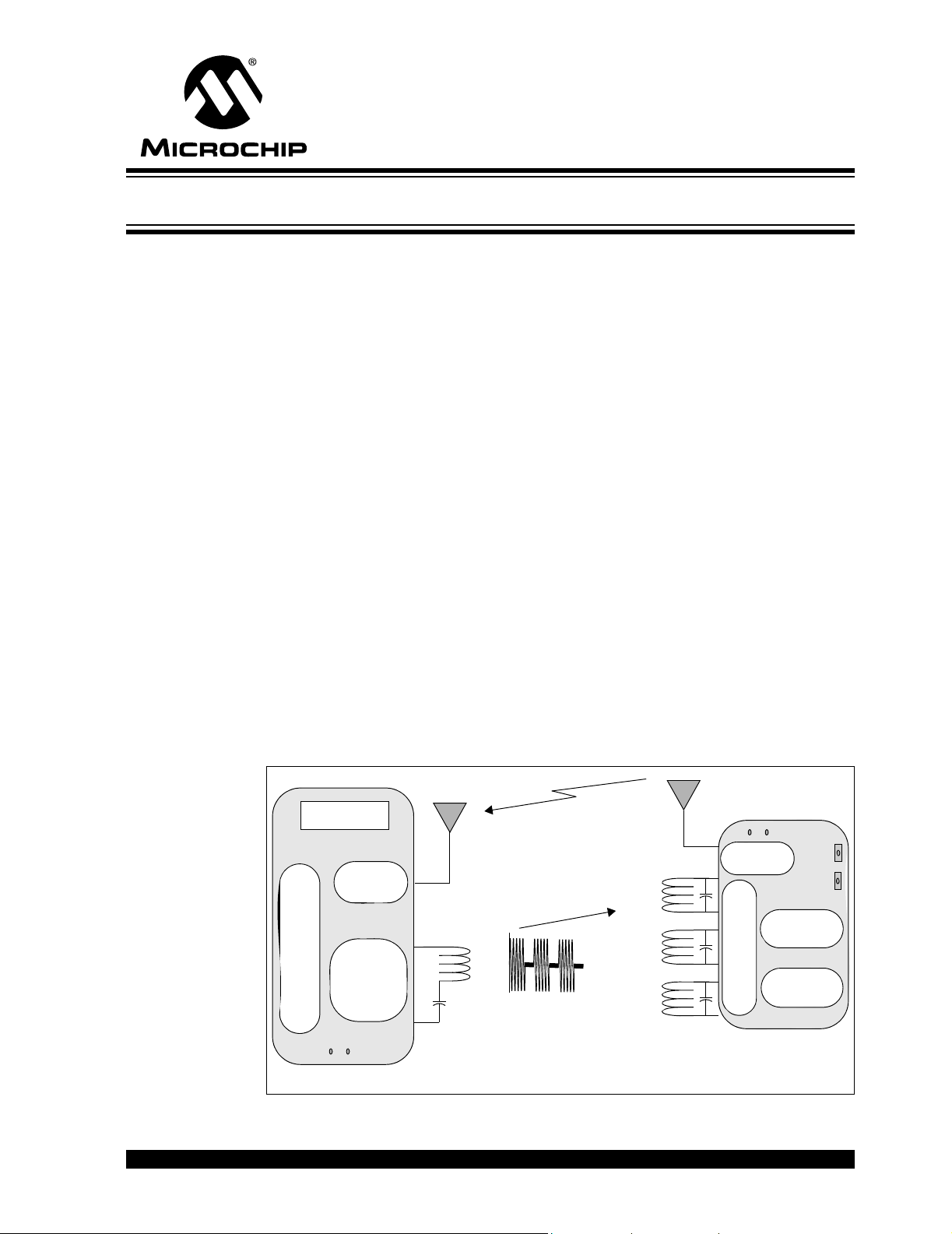
Chapter 2. System Overview ........................................................................................ 7
2.1 Overview ........................................................................................................ 7
2.2 Operational Overview ..................................................................................... 8
2.3 Features ....................................................................................................... 10
Chapter 3. Hardware and Firmware Overview .......................................................... 11
3.1 Introduction ................................................................................................... 11
3.2 MCP2030 Base Station Demo Board ........................................................... 11
3.3 MCP2030 Transponder Demo Board ........................................................... 14
Appendix A. Schematic and Layouts ........................................................................ 19
A.1 Introduction .................................................................................................. 19
A.2 Transponder Demo Board - Schematic ...................................................... 20
A.3 Transponder Demo Board - Top Layer and Silk Screen ............................ 21
A.4 Transponder Demo Board - Bottom Layer ................................................. 21
A.5 Base Station Demo Board - Schematic (Page 1) ..................................... 22
A.6 Base Station Demo Board - Schematic (Page 2) ..................................... 23
A.7 Base Station Demo Board - Top Layer and Silk Screen .......................... 24
A.8 Base Station Demo Board - Bottom Layer ............................................... 24
Appendix B. Bill of Materials (BOM) .......................................................................... 25
B.1 Introduction .................................................................................................. 25
Worldwide Sales and Service .................................................................................... 30
© 2006 Microchip Technology Inc. DS51637A-page iii
Page 4

MCP2030 Bidirectional Communication Demo Kit User’s Guide
NOTES:
DS51637A-page iv © 2006 Microchip Technology Inc.
Page 5

MCP2030 BIDIRECTIONAL
COMMUNICATION DEMO KIT
USER’S GUIDE
Preface
NOTICE TO CUSTOMERS
All documentation becomes dated, and this manual is no exception. Microchip tools and
documentation are constantly evolving to meet customer needs, so some actual dialogs
and/or tool descriptions may differ from those in this document. Please refer to our web site
(www.microchip.com) to obtain the latest documentation available.
Documents are identified with a “DS” number. This number is located on the bottom of each
page, in front of the page number. The numbering convention for the DS number is
“DSXXXXXA”, where “XXXXX” is the document number and “A” is the revision level of the
document.
For the most up-to-date information on development tools, see the MPLAB
Select the Help menu, and then Topics to open a list of available on-line help files.
®
IDE on-line help.
INTRODUCTION
This chapter contains general information that will be useful to know before using the
MCP2030 Bidirectional Communication Demo Kit. Items discussed in this chapter
include:
• Document Layout
• Conventions Used in this Guide
• Recommended Reading
• The Microchip Web Site
• Customer Support
DOCUMENT LAYOUT
This document describes the MCP2030 Bidirectional Communication Demo Kit. The
manual layout is as follows:
• Chapter 1. “Quick Start” – Describes the MCP2030 Bidirectional
Communication Demo Kit set-up instructions.
• Chapter 2. “System Overview” – A system overview of the MCP2030
Bidirectional Communication Demo Kit is discussed.
• Chapter 3. “Hardware and Firmware Overview” – Describes the MCP2030
Bidirectional Communication Demo Kit hardware and firmware.
• Appendix A. “Schematic and Layouts” – Shows the schematic and board
layouts for the MCP2030 Bidirectional Communication Demo Kit.
• Appendix B. “Bill of Materials (BOM)” - Lists the parts used to build the demo
boards that make up MCP2030 Bidirectional Communication Demo Kit.
© 2006 Microchip Technology Inc. DS51637A-page 1
Page 6
MCP2030 Bidirectional Communication Demo Kit User’s Guide
CONVENTIONS USED IN THIS GUIDE
This manual uses the following documentation conventions:
DOCUMENTATION CONVENTIONS
Description Represents Examples
Code (Courier font):
Plain characters Sample code
Filenames and paths
Angle brackets: < > Variables <label>, <exp>
Square brackets [ ] Optional arguments MPASMWIN [main.asm]
Curly brackets and pipe
character: { | }
Lowercase characters in
quotes
Ellipses... Used to imply (but not show) addi-
0xnnn A hexadecimal number where n is a
Italic characters A variable argument; it can be either a
Interface (Arial font):
Underlined, italic text
with right arrow
Bold characters A window or dialog button to click OK, Cancel
Characters in angle
brackets < >
Documents (Arial font):
Italic characters Referenced books MPLAB
Choice of mutually exclusive arguments; An OR selection
Type of data
tional text that is not relevant to the
example
hexadecimal digit
type of data (in lowercase characters)
or a specific example (in uppercase
characters).
A menu selection from the menu bar File > Save
A key on the keyboard <Tab>, <Ctrl-C>
#define START
c:\autoexec.bat
errorlevel {0|1}
“filename”
list
[“list_option...,
“list_option”]
0xFFFF, 0x007A
char isascii (char,
ch);
®
IDE User’s Guide
RECOMMENDED READING
It is recommended that you become familiar with the documents listed below, prior to
using the MCP2030 Bidirectional Communication Demo Kit.
Telecontrolli Data Sheet, “AMHRRQ3-433” , www.telecontrolli.com,
(DS.0015-1.pdf)
Telecontrolli Data Sheet, “AMHRR3-433”, www.telecontrolli.com,
(DS.0016-9.pdf)
Application Note AN710, “Antenna Circuit Design”, (DS00710)
Application note describing LF antenna circuit design for RFID applications.
Application Note AN959, “Using the PIC16F639 MCU for Smart Wireless
Communications” (DS00959)
Application note describing the PIC16F639 as a suitable microcontroller for
bidirectional communications and low-frequency sensing applications.
Application Note AN1024, “PKE System Design Using the PIC16F639” (DS01024)
Application note describing the PIC16F639 for bidirectional communication
applications.
DS51637A-page 2 © 2006 Microchip Technology Inc.
Page 7

MCP2030 Bidirectional Communication Demo Kit User’s Guide
PICkit™ 2 Microcontroller Programmer User’s Guide (DS51553)
Consult this document for instructions on how to use the PICkit 2 Microcontroller
Programmer hardware and software.
PIC12F635/PIC16F636/639 Data Sheet (DS41232)
Data sheet for the PIC12F635/PIC16F636/639 8/14-pin Flash-based, 8-bit CMOS
microcontrollers with nanoWatt technology.
PIC18F2585/2680/4585/4680 Data Sheet (DS39625)
Data sheet for the PIC18F2585/2680/4585/4680 28/40/44-pin enhanced Flash
microcontrollers with ECAN
MCP2030 Data Sheet, “Three-Channel Analog Front-End Device“ (DS21981)
Data sheet for the MCP2030 device.
TC4421/TC4422 Data Sheet, “High-Speed MOSFET Drivers” (DS21420)
Data sheet for the TC4421/TC4422 9A High-Speed MOSFET Driver. Gives an
overview of the device including electrical characteristics.
MCP3421 Data Sheet, “18-Bit Delta-Sigma Analog-to-Digital Converter with I
Interface and On-Board Referece” (DS22003)
Data sheet for the MCP3421 18-Bit Delta-Sigma Analog-to-Digital Converter.
™
technology, 10-bit A/D and nanoWatt technology.
2
C
THE MICROCHIP WEB SITE
Microchip provides online support via our web site at www.microchip.com. This web
site is used as a means to make files and information easily available to customers.
Accessible by using your favorite Internet browser, the web site contains the following
information:
• Product Support – Data sheets and errata, application notes and sample
programs, design resources, user’s guides and hardware support documents,
latest software releases and archived software
• General Technical Support – Frequently Asked Questions (FAQs), technical
support requests, online discussion groups, Microchip consultant program
member listing
• Business of Microchip – Product Selector Guide, latest Microchip press
releases, listing of seminars and events, listings of Microchip sales offices,
distributors and factory representatives
CUSTOMER SUPPORT
Users of Microchip products can receive assistance through several channels:
• Distributor or Representative
• Local Sales Office
• Field Application Engineer (FAE)
• Technical Support
• Development Systems Information Line
Customers should contact their distributor, representative or field application engineer
for support. Local sales offices are also available to help customers. A listing of sales
offices and locations is included in the back of this document.
Technical support is available through the web site at: http://support.microchip.com
© 2006 Microchip Technology Inc. DS51637A-page 3
Page 8

MCP2030 Bidirectional Communication Demo Kit User’s Guide
DOCUMENT REVISION HISTORY
Revision A (December 2006)
• Initial Release of this Document.
DS51637A-page 4 © 2006 Microchip Technology Inc.
Page 9
1.1 INTRODUCTION
This section provides the user a quick step-by-step instruction guide on how to set-up
the MCP2030 Bidirectional Communication Demo Kit.
1.1.1 Transponder Unit
Connect power to the Transponder unit by inserting a 3V NiHM (CR2032) battery to the
battery holder in the bottom side of the Transponder. When the Transponder is
powered on, it is waiting for a 125 kHz low frequency (LF) command from the Base
Station unit. On the PCB, there are three LF antenna coils: One large air-core coil on
the bottom side and two ferrite-core coils on the top side. These three coils detect
125 kHz low frequency (LF) signals from x, y, and z directions. The Transponder also
has a SAW (Surface Acoustic Wave) based UHF transmitter. A rectangular loop trace
on the PCB is the UHF antenna. The Transponder has two LED diodes. A green LED
(D6) will blink when the Transponder receives a valid LF command, and a red LED (D7)
will blink when it transmitting an UHF response.
MCP2030 BIDIRECTIONAL
COMMUNICATION DEMO KIT
USER’S GUIDE
Chapter 1. Quick Start
Top Sid e
UHF
Antenna
125 kHz
Air Core
Antenna Coil
PICkit™ 2
Debug Express
Bottom Side
3V Lithium
Battery
© 2006 Microchip Technology Inc. DS51637A-page 5
Page 10
MCP2030 Bidirectional Communication Demo Kit User’s Guide
1.1.2 Base Station Unit:
Supply power to the Base Station unit with a 9V - 18V power supply. As soon as the
power is supplied, the LED D2 will light on, and the unit starts transmitting an LF
command.The unit also waits for the responses from the Transponder at any time,
except during the transmission of the LF command. When the unit receives a valid
response from the Transponder, the LED D3 will blink and the received Transponder
ID and RSSI (Received Signal Strength Indicator) value will be displayed on the LCD.
MPLAB® ICD 2
Programming Jack
9V
Power
Supply
UHF
Antenna
UHF Receiver
Module
125 kHz LF
Antenna
1.1.3 When both the Base Station and Transponder units are
powered-on:
When the two units are powered-on, they will communicate by themselves. The Base
Station sends a 125 kHz LF command and the Transponder responds to the command.
When the Transponder is placed within about 2 meters to the Base Station unit, the two
units may have a successful communication with each other and the Base Station unit
will display the received Transponder ID and RSSI value on the LCD. This is called a
bidirectional communication. User can test the RSSI by moving the Transponder within
the Base Station’s LF field. The RSSI value will increase as the Transponder comes
closer to the Base Station antenna and decrease as moves away from it. The two units
are communicating with each other as long as the boards are powered. You can also
test one directional communication from the Transponder to the Base Station unit by
pressing button switch (SW3 or SW4) on the Transponder. The range of the one
directional communication is about 20 meters.
This MCP2030 Bidirectional Communication Demo Kit shows you how to create a
smart hands-free bidirectional communication system using the stand-alone MCP2030
and microcontroller. All MCU firmware used for both the Transponder and Base Station
units are included in the CD ROM provided with the MCP2030 Bidirectional Communication Demo Kit. The user can easily modify the firmware for their own applications.
DS51637A-page 6 © 2006 Microchip Technology Inc.
Page 11
2.1 OVERVIEW
This section describes how to use the MCP2030 Bidirectional Communication Demo
Kit.
The MCP2030 Bidirectional Communication Demo Kit consists of two Transponders
and a Base Station unit. The Transponder consists of an MCP2030 (stand-alone
three-axis analog front-end device), a PIC16F636, and an MCP3421(18-bit
delta-sigma analog-to-digital converter). Unlike the existing PKE Reference Design
System (P/N: APGRD001) from Microchip Technology Inc., this Transponder uses
stand-alone devices for the bidirectional passive keyless entry (PKE) operation. This
system also demonstrates the received signal strength indicator (RSSI) function using
the MCP3421 delta-sigma ADC. When the Transponder receives a Base Station command, it transmits its ID and sampled RSSI value. By monitoring or mapping the RSSI
values, the user can estimate location or motion of the transponder with respect to the
Base Station unit. For example, for the automotive passive keyless entry (PKE) applications, the Base Station mounted inside the vehicle can determine whether the transponder is located inside or outside of the vehicle, or in the front or back seat in the
vehicle.
The Base Station unit consists of a PIC18F4680, a low frequency (LF) power amplifier,
an LF receiver section, a 434 MHz UHF receiver module, an LCD display, and
CAN/LIN transceiver sections. The components in the LF receiver section and the
CAN/LIN transceiver sections are populated on the PCB for future use, but their
functions are not utilized for this demo version. Any user who needs these features can
contact Microchip Technology Inc. for further information.
The MCP2030 Bidirectional Communication Demo Kit has been designed for easy
modification by customers. The firmware of both the Transponder and Base Station
units can be easily modified using the MPLAB
MCP2030 BIDIRECTIONAL
COMMUNICATION DEMO KIT
Chapter 2. System Overview
®
in-circuit serial programmers.
USER’S GUIDE
Response
LCD
434 MHz AM
Receiver
(PIC18F4680)
Microcontroller
Base Station Transponder
LF
Transmitter/
Receiver
LED
125 kHz
LC Series
Resonant Circuit
LF Command
(125 kHz)
(UHF)
Ant. X
Ant. Y
Ant. Z
125 kHz
LC Parallel
Resonant Circuit
434 MHz
Transmitter
(PIC16F636)
(MCP2030)
Analog Front-End
LED
Button
SW
MCU
ADC
(MCP3421)
FIGURE 2-1: MCP2030 Bidirectional Communication System Block Diagram.
© 2006 Microchip Technology Inc. DS51637A-page 7
Page 12

MCP2030 Bidirectional Communication Demo Kit User’s Guide
2.2 OPERATIONAL OVERVIEW
When the MCP2030 Base Station unit is powered on using a 9 V power supply and the
MCP2030 transponder demo board is powered-on using a 3V lithium battery, the
system works as follows:
(a) The Base Station unit transmits an LF command. Requesting the Transponder’s ID
and RSSI data.
(b) When the Transponder receives the LF command, it transmits its 32-bit ID and RSSI
data via the UHF (434 MHz) link.
(c) When the Base Station unit receives the response from the Transponder, it displays
the Transponder ID and RSSI value on the LCD.
(d) The system repeats steps (a) through (c) as long as the power is supplied.
(e) If the button switch SW3 or SW4 on the Transponder is pressed, the Transponder
transmits the button data (SW3: Unlock door, SW4: Lock door). The Base Station unit
displays the button message on the LCD.
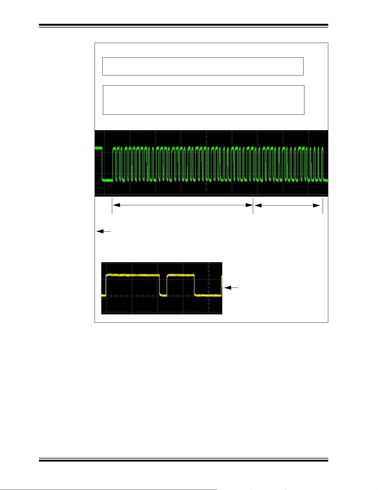
Figure 2-2 shows the communication sequence between the Base Station and the
Transponder units. Figure 2-3 shows the Base Station’s LF command and the
demodulated data by the MCP2030.
10 bit LF Command
from Base Station
Change back
Demodulated data output
from MCP2030
MCP3421
converts
RSSI to digital
values
Transponder Data Stream:
Header + 32 ID bits + 16 RSSI bits + 6 Parity bits + Stop bit
= Header + 54 Data bits + 1 Stop bit
MCP2030 configuration
register for
demodulated output
Continuous LF for
RSSI Sample
MCU Sends
a Soft Reset
Command to
MCP2030
ADC conversion
Completed here
FIGURE 2-2: Base Station Command and Transponder Response.
at pin 9
of U1
at pin 3
of U3
at pin 8
of U3
at pin 5
of U3
DS51637A-page 8 © 2006 Microchip Technology Inc.
Page 13

System Overview
10 bit LF Command
from Base Station
Demodulated data output
from MCP2030
AGC Stabilization time
(4 ms)
Gap for 500 μ s
MCP3421
converts
RSSI to digital
values
Transponder Data Stream:
Header + 32 ID bits + 16 RSSI bits + 6 Parity bits + Stop bit
= Header + 54 Data bits + 1 Stop bit
LF Command from Base Station
Change back
MCP2030
Wake-Up Filter
Demodulated Data:
1100-0011-Parity-Stop = C3 (hex)
when the Base Station transmits
LSB first.
Configuration
Register
Continuous LF for
RSSI Sample
MCU Sends
a Soft Reset
Command to
MCP2030
ADC conversion
Completed here
Reading
ADC Conversion Data for RSSI
SPI Command
for RSSI Output
I2C Command
for ADC
FIGURE 2-3: Received Base Station Command and Demodulated Data.
Input Coil Voltage
at pin 9 of U1
at pin 3 of U3
at pin 8 of U3
for RSSI data
© 2006 Microchip Technology Inc. DS51637A-page 9
Page 14

MCP2030 Bidirectional Communication Demo Kit User’s Guide
2.3 FEATURES
2.3.1 MCP2030 Base Station Unit
Features of the Base station Unit are as follows:
• Send an LF command continuously requesting the Transponder ID and RSSI data
• Display the received Transponder responses
• MPLAB
Note: LF talkback, CAN and LIN feature support: Components are populated, but
2.3.2 MCP2030 Transponder Unit
Features of the Transponder are as follows:
• Detect the LF command
• Sample the RSSI values
• Transmit 32 bit Transponder ID and 16 bit RSSI data
• Two push button switches (SW3 and SW4) for Unlock and Lock door commands
• Two LED outputs:
- Green LED that blinks when the Transponder receives a valid LF command.
- Red LED that blinks when the Transponder is transmitting RF data or
®
ICD 2 In Circuit Serial Programming™ (ICSP™)
not used for this demo version.
receiving invalid LF command.
DS51637A-page 10 © 2006 Microchip Technology Inc.
Page 15

MCP2030 BIDIRECTIONAL
COMMUNICATION DEMO KIT
Chapter 3. Hardware and Firmware Overview
3.1 INTRODUCTION
The following section provides an overview of the hardware and MCU firmware
algorithm used in the MCP2030 Bidirectional Communication Demo Kit.
3.2 MCP2030 BASE STATION DEMO BOARD
3.2.1 Technical Specifications
Normal Operating Voltage: 9 - 18V, Current Rating > 500 mA
LF Frequency
(LF Command Frequency)
UHF AM Receiving Frequency: 433.92 MHz
Liquid Crystal Display (LCD): 2x16 characters
Communication Protocols: See
USER’S GUIDE
125 kHz
Figure 2-2, Figure 3-1, Figure 3-2
3.2.2 Microcontroller (PIC18F4680)
The PIC18F4680 is used in this unit. The MCU provides an 125 kHz PWM for LF
command and decodes incoming Transponder responses. If the response is valid, it
displays the received data on the LCD and also blinks the LED D3. The PIC18F4680
has both a CAN controller and a LIN compatible EUSART features. The CAN and LIN
transceiver components are populated on the Base Station Demo Board, but their functions are not implemented for this demo version.
3.2.3 433.92 MHz UHF Receiver Module
The Base Station Demo Board uses a 433.92 MHz AM super-regenerative compact
hybrid receiver module. The AM UHF receiver receives the responses from the
Transponder. The receiver has very high frequency stability over a wide operating
temperature and tolerance of mechanical vibrations or manual handling. The AM
receiver module has about -90 dBm of input sensitivity. The user can use their own
receiver module of any frequency of interest as long as the frequency and
modulation/demodulation method matches with those of the transmitter on the
Transponder.
3.2.4 LCD
A standard 16 pin 2x16 monochromes LCD is used to display the response from the
Transponder.
© 2006 Microchip Technology Inc. DS51637A-page 11
Page 16

MCP2030 Bidirectional Communication Demo Kit User’s Guide
3.2.5 125 kHz Low Frequency Command Initiator
The 125 kHz PWM from the PIC18F4680 is power boosted by the MOS FET driver
(TC4422). The PWM square pulse becomes a sine wave as the current passes through
the LC series resonant circuit formed by L1 and C2, C3, and C4 on the Base Station
Demo Board. The current that is passing through the L1 generates a magnetic field.
When this magnetic field transmitted from the Base Station Demo Board is passing
through the Transponder Demo Board’s antenna coil, it produces a voltage. This
voltage is detected by the MCP2030 LF front-end device and the information carried on
the voltage is processed by the PIC16F636 microcontroller on the transponder.
See Recommended Reading for more details of the near-field magnetic coupling
principles.
3.2.6 Power
Power can be supplied through J1 power jack. The voltage should be in the range of
9 - 18 VDC with a current rating greater than 500 mA.
3.2.7 MCU FIRMWARE ALGORITHM
The bidirectional communication method between the Base Station Demo Board and
Transponder Demo Board is shown in Figure 2-2. The Base Station Demo Board sends
an LF command, receives the responses from the Transponder Demo Board, and displays the received responses on the LCD. The Base Station Demo Board repeats the
transmitting and receiving functions as long as its power supply is connected.
Figure 3-1 shows the LF command data format and waveform. The receiving data for-
mat is shown in Figure 3-5. The MCU firmware for the communication algorithm is
included on the MCP2030 Bidirectional Communication Demo Kit CD ROM.
AGC Stabilization Time
4ms
High Duration
AGC Stabilization Time
Gap
500 ms
Gap
Wake-Up Filter
2ms
High Duration
Wake-Up Filter
Low Duration
Transmitting Data: LSB First
2ms
Command Type
+ Continuous LF
3C+Parity + Stop bit
+LF turns-on for 50 ms
Receiving Data: LSB First
Command Type (3C)
= 1100 0011P
= LSB first of 3C (hex)
Continuous LF Field
This allows the Transponder
to sample the RSSI data
Waiting for Response
32 bit ID+RSSI+Parity Bits
(Parity bit per byte)
Stop bit
FIGURE 3-1: Base Station Demo Board LF Command Data Format.
DS51637A-page 12 © 2006 Microchip Technology Inc.
Page 17

MCP2030 Bidirectional Communication Demo Kit User’s Guide
The LF command Base Station Demo Board consists of a 125 kHz carrier modulated
as follows:
1: 4 ms ON for AFE’s AGC stabilization.
2: 500 µs OFF.
3: 2 ms ON followed by a 2 ms OFF (AFE’s output enable filter). This pattern is
dependant on the configuration setting of the receiving AFE.
4: 10 bit of command type (3C), parity, and Stop bit. The bits are transmitted Least
Significant bits (LSb) first. The data is encoded with PWM method. (see
Figure 3-2).
5: 50 ms ON for RSSI sample.
6: Waiting for a valid response from the Transponder.
500 µs
250 µs
500 µs
Bit Period
FIGURE 3-2: PWM Data Encoding Format.
250 µs
LOGIC ‘0’
LOGIC ‘1’
© 2006 Microchip Technology Inc. DS51637A-page 13
Page 18

MCP2030 Bidirectional Communication Demo Kit User’s Guide
3.3 MCP2030 TRANSPONDER DEMO BOARD
3.3.1 Technical Specifications
LF Input Frequency: 125 kHz
LF Input Modulation Format: Amplitude Modulation
Encoding Method: Pulse Width Modulation (PWM)
Operating Voltage: 2 - 3.6V. See Note 1
LF Input Sensitivity: ~3 mVPP. See Note 2
LF Detection Range: Up to 3 meters
Transmitting Frequency: 433.92 MHz
UHF Range: Up to ~ 20 meters
Bidirectional Communication Range Up to 3 meters
Note 1: The minimum requirement for V
the V
stable.
2: Contact Microchip Technology Inc. for the device option with higher
than 3 mVpp sensitivity.
less than 2.7V, the ADC result of the RSSI value may not be
DD
3.3.2 Microcontroller (PIC16F636)
of the MCP3421ADC is 2.7V. For
DD
The Transponder Demo Board uses a PIC16F636 microcontroller. This MCU is the
same device that is used inside the PIC16F639 which is a dual die package device
(PIC16F639 = PIC16F636 die + MCP2030 die in a single 20-pin package). The MCU
interfaces with the MCP2030 stand-alone analog front-end device for LF
communications and the MCP3421 delta-sigma analog-to-digital converter for RSSI
data conversion. When the MCU is first powered-up, it writes the MCP2030
configuration registers and also writes the configuration register of the MCP3421 ADC
(for 16 bit and one-shot mode).The MCP3421 stays in a low power standby mode after
one conversion. The MCU also stays in a low power sleep mode while the MCP2030
is looking for a valid LF command.
The MCU is waken up by the demodulated output from the MCP2030 or by a button
switch event (SW3 and SW4). The MCU decodes the demodulated output data from
the MCP2030. If the data is a valid command, it blinks the green LED (D6) and reads
the RSSI value by controlling the MCP3421 ADC. Once the RSSI value is acquired, the
MCU feeds the transponder ID and the RSSI data into the 433.92 MHz UHF
transmitter. The transmitted data from the UHF transmitter is detected by the RF
receiver in the Base Station Demo Board and the data is displayed on the LCD.
When a button switch is pressed, the MCU feeds a corresponding data into the UHF
transmitter. The red LED (D7) blinks each time the transponder transmits the UHF
response. The red LED also blinks when the transponder receives invalid data.
3.3.3 Three-Input LF (125 kHz) Front-End (MCP2030)
The MCP2030 detects the Base Station Demo Board’s LF command using three LF
antenna coils that are mounted on the Transponder Demo Board PCB. The Configuration registers of the MCP2030 are configured by the MCU when the Transponder Demo
Board is powered up the first time, and are re-configured during operation. The MCU
controls the MCP2030 for two different outputs: (a) Demodulated data and (b)
Received Signal Strength Indicator output (RSSI). When it is detecting input signals,
the device is configured for the demodulated data output. Once the MCU finds a valid
LF command, then the MCU re-configures the MCP2030 for the RSSI output. In this
case, the MCP2030 outputs the RSSI current that is proportional to the LF input signal
DS51637A-page 14 © 2006 Microchip Technology Inc.
Page 19
MCP2030 Bidirectional Communication Demo Kit User’s Guide
strength. This current output is fed into a resistor and the voltage across the resistor is
fed into the MCP3421 ADC input pin. The converted16-bit ADC output is then fed into
the MCU.
The function of the MCP2030 is controlled by its configuration register settings. Highly
intelligent signal detection and response (bidirectional communications) is possible by
utilizing the MCP2030 configuration register settings. The user can easily change or
modify the included firmware for different settings of the MCP2030 configuration
registers for their own applications.
3.3.4 UHF Transmitter (433.92 MHz)
A 433.92 MHz UHF transmitter is used to transmit the Transponder Demo Board data
to the Base Station Demo Board. The UHF transmitter is based on a surface acoustic
wave (SAW) resonator. The transmitter is turned on during the high duration of the data
and off during the low duration of the bit data.
Note: The design and layout of this transmitter is not sufficient to ensure
compliance with EC or FCC regulations.
3.3.5 Analog-to-Digital Converter (MCP3421)
The Transponder Demo Board uses an MCP3421 ADC to convert the analog RSSI
output of the MCP2030 to digital data. The MCP3421 is a delta-sigma analog-to-digital
converter with 12, 14, 16, and 18 bit mode options. In this demo board, the converter
is configured for the 16 bit and one-shot mode. When the transponder is powered-up,
the MCU sends an I
conversion. After one conversion, the device stays in a low power standby mode.
During this mode, the device draws only about 1 µA. When the MCP2030 analog
front-end device receives a valid Base Station command, then the MCU sends an I
read command to the MCP3421 ADC for the analog-to-digital data conversion. At this
moment, the Base Station Demo Board transmits a continuous LF signal for about
50 ms allowing the MCP2030 to collect the RSSI values. The RSSI voltage across the
RSSI load resistor is fed into the MCP3421 input pin. After the MCU sends the I
command, it is waiting for the MCP3421 to complete the conversion by checking the
RDY
bit of the MCP3421 output. In typical operation, it takes about 50 ms to complete
a 16 bit conversion. See Figure 2-2 and Figure 2-3 for more information on the ADC
operation.
2
C write command to the MCP3421 for one-shot mode and 16 bit
2
C read
2
C
TABLE 3-1: PIC16F636 I/O CONNECTIONS
PORT Pin Function Notes
Port A
RA0 Switch 4 ICSP™ Data
RA1 ICSP Clock
RA2 Switch 3
RA3 ICSP MCLR
RA4 LFDATA Input from MCP2030, SPI SDIO for MCP2030
RA5 SPI SCLK Output for MCP2030
Port C
RC0 RF Active LED
RC1 SPI CS
RC2 I2C SDA for MCP3421
RC3 I
RC4 Valid LFDATA Input Indicator LED
RC5 RF Data Out
© 2006 Microchip Technology Inc. DS51637A-page 15
output for MCP2030
2
C SCL for MCP3421
Page 20

MCP2030 Bidirectional Communication Demo Kit User’s Guide
3.3.6 Programming of the Transponder
The Transponder Demo Board has a Programming Connector (J1) for In-Circuit Serial
Programming™ (ICSP™). See Figure 3-3 for the J1 Programming Connector. The
transmitter can therefore be re-programmed using the PICkit
removing the microcontroller from the board.
®
2 (or PICkit® 1) without
MCLR
ICSPDAT
ICSPCLK
no connection
1
V
2
CC
V
3
SS
4
5
6
FIGURE 3-3: J1 Programming Connector.
3.3.7 Power
The Transponder Demo Board is powered by a standard Lithium 3V coin cell battery.
3.3.8 Microcontroller Firmware Algorithm
When the Transponder Demo Board is powered on, the PIC16F636 (MCU) programs
the configuration registers of the MCP2030 and also the configuration register of the
MCP3421 (ADC). After these set-up procedures, the MCU enters a low-power sleep
mode while the MCP2030 is looking for a valid LF command. The MCU is waken-up by
the demodulated output from the MCP2030 or button switch event. If the MCU receives
a valid demodulated data from the MCP2030, then it transmits its 32 bit transponder ID
followed by the 16 bit received signal strength indicator (RSSI) data. If the MCU is
waken-up by a switch event (SW3 and SW4), it transmits the corresponding switch
event data. The data is always attached to the header (See Figure 3-5). The Transponder ID is set to “04234567” and programmed in the EEPROM. The RSSI data is proportional to the LF signal strength. Therefore, the RSSI data increases as the
Transponder Demo Board comes closer to the Base Station Demo Board. The Transponder Demo Board transmits each byte LSB first and also transmits a parity bit at
end of each byte. See Figure 3-5 for more details of the Transponder Demo Board data
stream. Figure 3-4 shows the firmware flow chart.
The MCU firmware is included in the MCP2030 Bidirectional Communication Demo Kit
CD ROM.
DS51637A-page 16 © 2006 Microchip Technology Inc.
Page 21

MCP2030 Bidirectional Communication Demo Kit User’s Guide
Power-up
MCU Programs the MCP2030
Configuration Registers
No
Button Pressed?
Yes
MCU wakes up
Encode the SW event data
SW3: Unlock Door
SW4: Lock Door
pin High?
ALERT
Yes
MCU Configure the MCP3421 ADC
for One-Shot and 16 bit Mode
while the MCP2030 detects input signals
MCU in Sleep Mode
No
Input Signal in?
Yes
Input Signal
Disappeared for
> 16 ms?
No
Meet wake-up
filter?
Yes
MCU wakes up
Send I2C Read Command
to the MCP3421 for RSSI
No
Yes
No
Soft Reset
Send Response via
RF Link
FIGURE 3-4: Communication Flow-Chart of the Transponder Demo Board.
© 2006 Microchip Technology Inc. DS51637A-page 17
Page 22
MCP2030 Bidirectional Communication Demo Kit User’s Guide
Ex: For the transponder ID = 04234567 and acquired RSSI value = C6CF
Transponder ID = 04-23-45-67 = 00000100-00100011-01000101-01100111
Acquired RSSI Data = C6-CF = 11000110-11001111
Ex: Transmitting data with LSB first:
0010000P-11000100P-10100010P-11100110P-01100011P-1110011P
Where P = Odd Parity bit of the byte
Transponder ID (32 bits + 4 Parity bits)
Header:
4 ms high duration + 500 µs low duration + 2 ms high duration + 2 ms low duration
Header Waveform
RSSI Data + Parity
(16 bits + 2 Parity bits)
FIGURE 3-5: EXAMPLE: Transponder Response for ID and RSSI
DS51637A-page 18 © 2006 Microchip Technology Inc.
Page 23

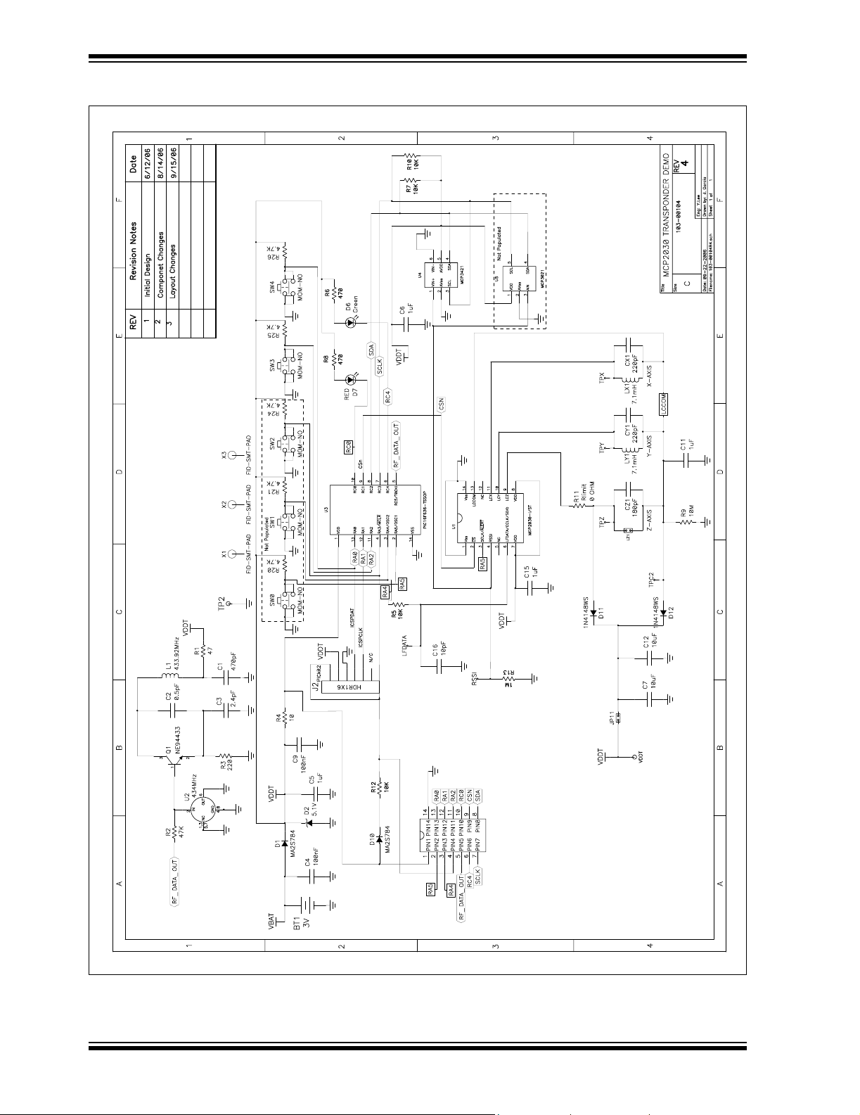
Appendix A. Schematic and Layouts
A.1 INTRODUCTION
This appendix contains the schematics and PCB layouts for the MCP2030 Bidirectional
Communication Demo Kit. This Appendix includes:
• Transponder Demo Board - Schematic (102-00104)
• Transponder Demo Board - Top Layer (with silk screen)
• Transponder Demo Board - Bottom Layer
• Base Station Demo Board - Schematic (Page 1) (102-00105)
• Base Station Demo Board - Schematic (Page 2) (102-00105)
• Base Station Demo Board - Top Layer (with silk screen)
• Base Station Demo Board - Bottom Layer
MCP2030 BIDIRECTIONAL
COMMUNICATION DEMO KIT
USER’S GUIDE
© 2006 Microchip Technology Inc. DS51637A-page 19
Page 24
MCP2030 Bidirectional Communication Demo Kit User’s Guide
A.2 TRANSPONDER DEMO BOARD - SCHEMATIC
M
DS51637A-page 20 © 2006 Microchip Technology Inc.
Page 25
MCP2030 Bidirectional Communication Demo Kit User’s Guide
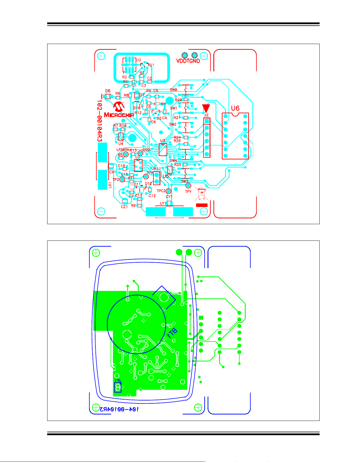
A.3 TRANSPONDER DEMO BOARD - TOP LAYER AND SILK SCREEN
A.4 TRANSPONDER DEMO BOARD - BOTTOM LAYER
© 2006 Microchip Technology Inc. DS51637A-page 21
Page 26

MCP2030 Bidirectional Communication Demo Kit User’s Guide
A.5 BASE STATION DEMO BOARD - SCHEMATIC (PAGE 1)
M
DS51637A-page 22 © 2006 Microchip Technology Inc.
Page 27

MCP2030 Bidirectional Communication Demo Kit User’s Guide
A.6 BASE STATION DEMO BOARD - SCHEMATIC (PAGE 2)
M
© 2006 Microchip Technology Inc. DS51637A-page 23
Page 28

MCP2030 Bidirectional Communication Demo Kit User’s Guide
A.7 BASE STATION DEMO BOARD - TOP LAYER AND SILK SCREEN
A.8 BASE STATION DEMO BOARD - BOTTOM LAYER
DS51637A-page 24 © 2006 Microchip Technology Inc.
Page 29

MCP2030 BIDIRECTIONAL
COMMUNICATION DEMO KIT
USER’S GUIDE
Appendix B. Bill of Materials (BOM)
B.1 INTRODUCTION
This appendix contains the bill of materials of the MCP2030 Bidirectional
Communication Demo Kit. This Appendix includes:
• Transponder Demo Board - Bill of Materials
• Base Station Demo Board - Bill of Materials
TABLE B-1: TRANSPONDER DEMO BOARD - BILL OF MATERIALS
Reference
Qty
Designator
1 BT1 HOLDER BATTERY COIN 20MM 1-CELL Keystone Electronics
1 C1 CAP CERAMIC 470PF 50V NP0 0603 Panasonic® - ECG ECJ-1VC1H471J
1 C2 CAP 0.5PF 50V CERAMIC 0603 SMD Panasonic - ECG ECJ-1VC1H0R5C
1 C3 CAP CERAMIC 2.4PF 50V C0G 0603 Rohm MCH185A2R4CK
2 C4, C9 CAP .10UF 16V CERAMIC X7R 0603 Kemet
4 C5, C6,
C11, C15
2 C7, C12 CAP CERAMIC 10UF 6.3V X5R 0603 Panasonic - ECG ECJ-1VB0J106M
1 C16 CAP CERM 10PF 10% 100V NP0 0603 AVX Corporation 06031A100KAT2A
1 Coin
Battery
2 CY1, CX1 CAP CERAMIC 220PF 50V 0603 SMD Panasonic - ECG ECJ-1VC1H221J
1 CZ1 CAP CERAMIC 180PF 50V 0603 SMD Panasonic - ECG ECJ-1VC1H181J
2 D1, D10 DIODE SCHOTTKY 30V 100MA SS-MINI Panasonic - SSG MA2S78400L
1 D2 DIODE ZENER 5.1V 0.35W SOT-23 Fairchild Semiconductor
1 D6 LED GREEN CLEAR 0805 SMD LITE-ON INC LTST-C170GKT
1 D7 LED RED CLEAR 0805 SMD LITE-ON INC LTST-C170CKT
2 D11, D12 DIODE SWITCH 75V 200MW SOD323 Diodes Inc 1N4148WS-7-F
1 J2 LOW PROFILE,SOLDERTAIL
1 JP11 HEADER,.1" ST MALE,1RW, 2PIN,
1 JP11 Shunt SHUNT,SHORTING BLOCKS,BLK,OPEN JAMECO VALUEPRO 7600-B-R
2 LY1, LX1 INDUCTOR, RFID TRANSPONDER Coilcraft 4308RV-715X_LB
1 LZ1 Precision wound Air Coils
1 Q1 TRANSISTOR NPN OSC FT=2GHZ
1 R1 RES 47.5 OHM 1/10W 1% 0603 SMD Panasonic - ECG ERJ-3EKF47R5V
1 R2 RES 47.5K OHM 1/10W 1% 0603 SMD Panasonic - ECG ERJ-3EKF4752V
Note 1: The components listed in this Bill of Materials are representative of the PCB assembly. The released BOM
used in manufacturing uses all RoHS-compliant components
CAP 1UF 16V CERAMIC F 0603 Panasonic - ECG ECJ-1VF1C105Z
BATTERY LITHIUM COIN
3 VOLT 20MM
HEADER,.1" ST MALE, 1RW, 6PIN,
(10) .025" PST,.23GOLDTAIL
Part will be Provided
SOT23
Description Manufacturer Part Number
®
103
®
Electronics Corp C0603C104K4RACTU
Energizer Battery
Company
——
——
——
NEC NE94433-T1B-A
CR2012
®
BZX84C5V1
© 2006 Microchip Technology Inc. DS51637A-page 25
Page 30

MCP2030 Bidirectional Communication Demo Kit User’s Guide
TABLE B-1: TRANSPONDER DEMO BOARD - BILL OF MATERIALS (CONTINUED)
Reference
Qty
Designator
1 R3 RES 221 OHM 1/10W 1% 0603 SMD Panasonic - ECG ERJ-3EKF2210V
1 R4 RES 10.0 OHM 1/10W 1% 0603 SMD Panasonic - ECG ERJ-3EKF10R0V
4 R5, R7,
RES 10.0K OHM 1/10W 1% 0603 SMD Panasonic - ECG ERJ-3EKF1002V
R10, R12
2 R6, R8 RES 475 OHM 1/10W 1% 0603 SMD Panasonic - ECG ERJ-3EKF4750V
1 R9 RES 10.0M OHM 1/10W 1% 0603 SMD Yageo
1 R11 RES ZERO OHM 1/10W 5% 0603 SMD Panasonic - ECG ERJ-3GEY0R00V
1 R13 RES 1.00M OHM 1/10W 1% 0603 SMD Yageo Corporation RC0603FR-071ML
3 R20, R21,
DO NOT POPULATE — —
R24
2 R25, R26 RES 4.75K OHM 1/10W 1% 0603 SMD Panasonic - ECG ERJ-3EKF4751V
3SW0, SW1,
SW2
LIGHT TOUCH SWITCH SMD 260GF
5MM - DO NOT POPULATE
2 SW3, SW4 LIGHT TOUCH SWITCH SMD 260GF
5MM
1 U1 Three-Channel Analog Front-End Device Microchip Technology Inc. MCP2030-I/ST
1 U2 RESONATOR SAW 433.92MHZ 1 PORT ECS Inc ECS-SDR1-4339-TR
1 U3 PIC16F636-TSSOP Microchip Technology Inc. PIC16F636-ST
1 U4 18-Bit Analog-to-Digital Converter with I2C
Interface and On-Board Reference
1 U5 DO NOT POPULATE — —
1 U6 SOCKET,IC,14PIN,MACHINE TOOLED
LOW PROFILE,SOLDERTAIL
Note 1: The components listed in this Bill of Materials are representative of the PCB assembly. The released BOM
used in manufacturing uses all RoHS-compliant components
Description Manufacturer Part Number
®
Corporation RC0603FR-0710ML
——
Panasonic - ECG EVQ-PLMA15
Microchip Technology Inc. PIC18F4680-I/P
JAMECO VALUEPRO 6100-14-R
TABLE B-2: BASE STATION DEMO BOARD - BILL OF MATERIALS
Reference
Qty
Designator
1ANTENNA
LEAD
5 C1, C7, C10,
WIRE 24AWG STRAND BLACK 6.8
INCHES LONG
CAP .1UF 50V CERM CHIP 1206 X7R Panasonic
C16, C24
1 C2 CAP .01UF 400V POLYPROPYLENE Panasonic - ECG ECQ-P4103JU
1 C5 CAP 2200PF 500V CERAMIC DISC
Y5P
1 C6 CAP CER 1UF 10V X5R RAD TDK
1 C8 CAP CERAMIC 100PF 50V NP0 1206 Yageo Corporation
1 C9 CAP CERAMIC 10000PF 50V NP0
1206
1 C11 CAP CERAMIC 470PF 50V NP0 1206 Kemet
1 C12 CAP 270PF 50V CERAMIC X7R 1206 Yageo Corporation CC1206KRX7R9BB271
1 C13 CAP 100UF 50V ELECT FC RADIAL Panasonic - ECG EEU-FC1H101
1 C14 CAP 47UF 10V ELECT FC RADIAL Panasonic - ECG EEU-FC1A470
1 C15 CAP 10UF 10V TANTALUM TE SMD Kemet
Note 1: The components listed in this Bill of Materials are representative of the PCB assembly. The released BOM
used in manufacturing uses all RoHS-compliant components.
Description Manufacturer Part Number
Alpha Wire Company 3050 BK005
®
- ECG ECJ-3VB1H104K
Panasonic - ECG D222K33Y5PL63L0R
®
Corporation FK28X5R1A105K
®
CC1206JRNPO9BN101
Panasonic - ECG ECJ-3FC1H103J
®
Electronics Corp C1206C471J5GACTU
®
Electronics Corp T491A106K010AT
DS51637A-page 26 © 2006 Microchip Technology Inc.
Page 31

MCP2030 Bidirectional Communication Demo Kit User’s Guide
TABLE B-2: BASE STATION DEMO BOARD - BILL OF MATERIALS (CONTINUED)
Reference
Qty
Designator
2 C17, C18, CAP 1UF 16V CERAMIC 0805 X5R Panasonic - ECG ECJ-2FB1C105K
2 C22, C23 CAP CERAMIC 20PF 50V NP0 1206 Yageo Corporation CC1206JRNPO9BN200
1 D1 DIODE ULTRA FST SW 600V 1A
DO-41
2 D2, D3 LED 2X3MM 565NM GRN WTR CLR
SMD
4 D4, D9, D10,
D11
2 D5, D8 DIODE SCHOTTKY 100V 1.5A D-64 International Rectifier 10MQ100NPBF
1 D6 DIODE ZENER 27V 1W 5% DO-41 Diodes Inc 1N4750A-T
2 D7, D13 DIODE SWITCH 75V 500MW MIN-
1 J1 CONN HEADER 6PS R/A DL .163
1 J2 CONN D-SUB PLUG R/A 9POS PCB AUTyco Electronics/Amp 5747250-4
1 J3 CONN MOD JACK 6-6 R/A PCB 50AU Tyco Electronics/Amp 5520470-3
1 J4 CONN POWER JACK 2.5MM PCB
1 L1 IND 160UH 500V AIR MC Davis Microchip-160mH
1 LCD1 LCD MODULE 16X2 CHARACTER Lumex
1 LCD
Connector
1 LCD
HEADER
1 R1 RES 392K OHM 1/4W 1% 1206 SMD Panasonic - ECG ERJ-8ENF3923V
1 R2 RES 11.0K OHM 1/4W 1% 1206 SMD Panasonic - ECG ERJ-8ENF1102V
1 R3 RES 10 OHM 1/4W 1% 1206 SMD Panasonic - ECG ERJ-8ENF10R0V
1 R4 RES 49.9 OHM 1/4W 1% 1206 SMD Panasonic - ECG ERJ-8ENF49R9V
1 R5 RES 162K OHM 1/4W 1% 1206 SMD Yageo Corporation 9C12063A1623FKHFT
1 R6 RES 3.92K OHM 1/4W 1% 1206 SMD Panasonic - ECG ERJ-8ENF3921V
1 R7 RES 16.5K OHM 1/4W 1% 1206 SMD Yageo Corporation 9C12063A1652FKHFT
1 R8 RES 64.9 OHM 1/4W 1% 1206 SMD Panasonic - ECG ERJ-8ENF64R9V
1 R9 RES 4.87K OHM 1/4W 1% 1206 SMD Yageo Corporation 9C12063A4871FKHFT
1 R10 RES 5.11K OHM 1/4W 1% 1206 SMD Panasonic - ECG ERJ-8ENF5111V
1 R12 RES 1.00K OHM 1/4W 1% 1206 SMD Panasonic - ECG ERJ-8ENF1001V
1 R13 RES 4.75K OHM 1/8W 1% 0805 SMD Yageo Corporation 9C08052A4751FKHFT
1 R14 RES 1.00K OHM 1/8W 1% 0805 SMD Panasonic - ECG ERJ-6ENF1001V
1 R15 RES 121 OHM 1/8W 1% 0805 SMD Panasonic - ECG ERJ-6ENF1210V
1 R16 RES 274 OHM 1/4W 1% 1206 SMD Panasonic - ECG ERJ-8ENF2740V
2 R18, R19 RES 15.0K OHM 1/8W 1% 0805 SMD Panasonic - ECG ERJ-6ENF1502V
1 R20 RES 24.9K OHM 1/8W 1% 0805 SMD Panasonic - ECG ERJ-6ENF2492V
1 R26 RES 30K OHM 1/8W 5% 0805 SMD Panasonic - ECG ERJ-6GEYJ303V
1 R27 RES 10.0K OHM 1/4W 1% 1206 SMD Panasonic - ECG ERJ-8ENF1002V
Note 1: The components listed in this Bill of Materials are representative of the PCB assembly. The released BOM
used in manufacturing uses all RoHS-compliant components.
1N5819 RECT SCHOTTKY 1A 40V
DO-214AA
IMELF
GOLD
CIRC
CONN SOCKET 16 PIN STRIP SAMTEC SSW-116-02-G-S
CONN HEADER 17POS .100 VERT TIN ValuePro 7000-1X17SG
Description Manufacturer Part Number
Diodes Inc UF1005-T
Lumex Opto/Components
Inc
Micro Commercial Co. SK14-TP
Diodes Inc LL4148-13
®
Tyco
Electronics/Amp 1-770969-1
CUI Inc PJ-102B
®
Opto/Components
Inc
SML-LX23GC-TR
LCM-S01602DTR/M
© 2006 Microchip Technology Inc. DS51637A-page 27
Page 32

MCP2030 Bidirectional Communication Demo Kit User’s Guide
TABLE B-2: BASE STATION DEMO BOARD - BILL OF MATERIALS (CONTINUED)
Reference
Qty
Designator
2 R28,R29 RES 4.75K OHM 1/4W 1% 1206 SMD Panasonic - ECG ERJ-8ENF4751V
2 S1, S2 SWITCH LT TOUCH 6X3.5 100GF SMD Panasonic - ECG EVQ-PJS04K
7 TP1 - TP7 TEST POINT PC MULTI PURPOSE
WHT
2 TP8 & TP9 TEST POINT PC MULTI PURPOSE
BLK
1 U1 9A High Speed MOSFET Driver Microchip Technology Inc. TC4422CAT
1 U2 Rail-to-Rail Input/Output, 10 MHz Op
Amp
1 U3 28/40-Pin High-Performance, Enhanced
Flash
1 U3 Socket IC Socket 40 PIN .600 GOLD Mill-Max Manufacturing
1 U4 Receiver AM Hybrid 433 MHz Module http://www.okwelectron-
1 U5 LIN Transceiver with Voltage Regulator Microchip Technology Inc. MCP201-I/SN
1 U6 Microcontroller with CAN High-Speed
CAN Transceiver
1 VR1 IC 5.0 100MA LDO VREG SOT23 National Semiconductor
1 Y1 CRYSTAL 20.000MHZ 20PF HC-49/US ECS Inc ECS-200-20-4X
Note 1: The components listed in this Bill of Materials are representative of the PCB assembly. The released BOM
used in manufacturing uses all RoHS-compliant components.
Description Manufacturer Part Number
Keystone Electronics
Keystone Electronics 5011
Microchip Technology Inc. MCP6022-I/SN
Microchip Technology Inc. PIC18F4680-I/P
Corp.
ics.com/index.html
Microchip Technology Inc MCP2551-I/SN
®
5012
110-43-640-41-001000
AMHRR3-433
®
LM3480IM3-5.0
DS51637A-page 28 © 2006 Microchip Technology Inc.
Page 33

MCP2030 Bidirectional Communication Demo Kit User’s Guide
NOTES:
© 2006 Microchip Technology Inc. DS51637A-page 29
Page 34

WORLDWIDE SALES AND SERVICE
AMERICAS
Corporate Office
2355 West Chandler Blvd.
Chandler, AZ 85224-6199
Tel: 480-792-7200
Fax: 480-792-7277
Technical Support:
http://support.microchip.com
Web Address:
www.microchip.com
Atlanta
Duluth, GA
Tel: 678-957-9614
Fax: 678-957-1455
Boston
Westborough, MA
Tel: 774-760-0087
Fax: 774-760-0088
Chicago
Itasca, IL
Tel: 630-285-0071
Fax: 630-285-0075
Dallas
Addison, TX
Tel: 972-818-7423
Fax: 972-818-2924
Detroit
Farmington Hills, MI
Tel: 248-538-2250
Fax: 248-538-2260
Kokomo
Kokomo, IN
Tel: 765-864-8360
Fax: 765-864-8387
Los Angeles
Mission Viejo, CA
Tel: 949-462-9523
Fax: 949-462-9608
Santa Clara
Santa Clara, CA
Tel: 408-961-6444
Fax: 408-961-6445
Toronto
Mississauga, Ontario,
Canada
Tel: 905-673-0699
Fax: 905-673-6509
ASIA/PACIFIC
Asia Pacific Office
Suites 3707-14, 37th Floor
Tower 6, The Gateway
Habour City, Kowloon
Hong Kong
Tel: 852-2401-1200
Fax: 852-2401-3431
Australia - Sydney
Tel: 61-2-9868-6733
Fax: 61-2-9868-6755
China - Beijing
Tel: 86-10-8528-2100
Fax: 86-10-8528-2104
China - Chengdu
Tel: 86-28-8665-5511
Fax: 86-28-8665-7889
China - Fuzhou
Tel: 86-591-8750-3506
Fax: 86-591-8750-3521
China - Hong Kong SAR
Tel: 852-2401-1200
Fax: 852-2401-3431
China - Qingdao
Tel: 86-532-8502-7355
Fax: 86-532-8502-7205
China - Shanghai
Tel: 86-21-5407-5533
Fax: 86-21-5407-5066
China - Shenyang
Tel: 86-24-2334-2829
Fax: 86-24-2334-2393
China - Shenzhen
Tel: 86-755-8203-2660
Fax: 86-755-8203-1760
China - Shunde
Tel: 86-757-2839-5507
Fax: 86-757-2839-5571
China - Wuhan
Tel: 86-27-5980-5300
Fax: 86-27-5980-5118
China - Xian
Tel: 86-29-8833-7250
Fax: 86-29-8833-7256
ASIA/PACIFIC
India - Bangalore
Tel: 91-80-4182-8400
Fax: 91-80-4182-8422
India - New Delhi
Tel: 91-11-4160-8631
Fax: 91-11-4160-8632
India - Pune
Tel: 91-20-2566-1512
Fax: 91-20-2566-1513
Japan - Yokohama
Tel: 81-45-471- 6166
Fax: 81-45-471-6122
Korea - Gumi
Tel: 82-54-473-4301
Fax: 82-54-473-4302
Korea - Seoul
Tel: 82-2-554-7200
Fax: 82-2-558-5932 or
82-2-558-5934
Malaysia - Penang
Tel: 60-4-646-8870
Fax: 60-4-646-5086
Philippines - Manila
Tel: 63-2-634-9065
Fax: 63-2-634-9069
Singapore
Tel: 65-6334-8870
Fax: 65-6334-8850
Taiwan - Hsin Chu
Tel: 886-3-572-9526
Fax: 886-3-572-6459
Taiwan - Kaohsiung
Tel: 886-7-536-4818
Fax: 886-7-536-4803
Taiwan - Taipei
Tel: 886-2-2500-6610
Fax: 886-2-2508-0102
Thailand - Bangkok
Tel: 66-2-694-1351
Fax: 66-2-694-1350
EUROPE
Austria - Wels
Tel: 43-7242-2244-39
Fax: 43-7242-2244-393
Denmark - Copenhagen
Tel: 45-4450-2828
Fax: 45-4485-2829
France - Paris
Tel: 33-1-69-53-63-20
Fax: 33-1-69-30-90-79
Germany - Munich
Tel: 49-89-627-144-0
Fax: 49-89-627-144-44
Italy - Milan
Tel: 39-0331-742611
Fax: 39-0331-466781
Netherlands - Drunen
Tel: 31-416-690399
Fax: 31-416-690340
Spain - Madrid
Tel: 34-91-708-08-90
Fax: 34-91-708-08-91
UK - Wokingham
Tel: 44-118-921-5869
Fax: 44-118-921-5820
12/08/06
DS51637A-page 30 © 2006 Microchip Technology Inc.
 Loading...