

Page 1
MCP1663
9V/12V/24V Output
Boost Regulator
Evaluation Board
User’s Guide
2015 Microchip Technology Inc. DS50002364A
Page 2

Note the following details of the code protection feature on Microchip devices:
YSTEM
CERTIFIED BY DNV
== ISO/TS 16949 ==
• Microchip products meet the specification contained in their particular Microchip Data Sheet.
• Microchip believes that its family of products is one of the most secure families of its kind on the market today, when used in the
intended manner and under normal conditions.
• There are dishonest and possibly illegal methods used to breach the code protection feature. All of these methods, to our
knowledge, require using the Microchip products in a manner outside the operating specifications contained in Microchip’s Data
Sheets. Most likely, the person doing so is engaged in theft of intellectual property.
• Microchip is willing to work with the customer who is concerned about the integrity of their code.
• Neither Microchip nor any other semiconductor manufacturer can guarantee the security of their code. Code protection does not
mean that we are guaranteeing the product as “unbreakable.”
Code protection is constantly evolving. We at Microchip are committed to continuously improving the code protection features of our
products. Attempts to break Microchip’s code protection feature may be a violation of the Digital Millennium Copyright Act. If such acts
allow unauthorized access to your software or other copyrighted work, you may have a right to sue for relief under that Act.
Information contained in this publication regarding device
applications and the like is provided only for your convenience
and may be superseded by updates. It is your responsibility to
ensure that your application meets with your specifications.
MICROCHIP MAKES NO REPRESENTATIONS OR
WARRANTIES OF ANY KIND WHETHER EXPRESS OR
IMPLIED, WRITTEN OR ORAL, STATUTORY OR
OTHERWISE, RELATED TO THE INFORMATION,
INCLUDING BUT NOT LIMITED TO ITS CONDITION,
QUALITY, PERFORMANCE, MERCHANTABILITY OR
FITNESS FOR PURPOSE. Microchip disclaims all liability
arising from this information and its use. Use of Microchip
devices in life support and/or safety applications is entirely at
the buyer’s risk, and the buyer agrees to defend, indemnify and
hold harmless Microchip from any and all damages, claims,
suits, or expenses resulting from such use. No licenses are
conveyed, implicitly or otherwise, under any Microchip
intellectual property rights.
Trademarks
The Microchip name and logo, the Microchip logo, dsPIC,
FlashFlex, flexPWR, JukeBlox, K
LANCheck, MediaLB, MOST, MOST logo, MPLAB,
OptoLyzer, PIC, PICSTART, PIC
SST, SST Logo, SuperFlash and UNI/O are registered
trademarks of Microchip Technology Incorporated in the
U.S.A. and other countries.
The Embedded Control Solutions Company and mTouch are
registered trademarks of Microchip Technology Incorporated
in the U.S.A.
Analog-for-the-Digital Age, BodyCom, chipKIT, chipKIT logo,
CodeGuard, dsPICDEM, dsPICDEM.net, ECAN, In-Circuit
Serial Programming, ICSP, Inter-Chip Connectivity, KleerNet,
KleerNet logo, MiWi, MPASM, MPF, MPLAB Certified logo,
MPLIB, MPLINK, MultiTRAK, NetDetach, Omniscient Code
Generation, PICDEM, PICDEM.net, PICkit, PICtail,
RightTouch logo, REAL ICE, SQI, Serial Quad I/O, Total
Endurance, TSHARC, USBCheck, VariSense, ViewSpan,
WiperLock, Wireless DNA, and ZENA are trademarks of
Microchip Technology Incorporated in the U.S.A. and other
countries.
SQTP is a service mark of Microchip Technology Incorporated
in the U.S.A.
Silicon Storage Technology is a registered trademark of
Microchip Technology Inc. in other countries.
GestIC is a registered trademarks of Microchip Technology
Germany II GmbH & Co. KG, a subsidiary of Microchip
Technology Inc., in other countries.
All other trademarks mentioned herein are property of their
respective companies.
© 2015, Microchip Technology Incorporated, Printed in the
U.S.A., All Rights Reserved.
ISBN: 978-1-63277-406-4
EELOQ, KEELOQ logo, Kleer,
32
logo, RightTouch, SpyNIC,
QUALITY MANAGEMENT S
DS50002364A-page 2 2015 Microchip Technology Inc.
Microchip received ISO/TS-16949:2009 certification for its worldwide
headquarters, design and wafer fabrication facilities in Chandler and
Tempe, Arizona; Gresham, Oregon and design centers in California
and India. The Company’s quality system processes and procedures
are for its PIC
devices, Serial EEPROMs, microperipherals, nonvolatile memory and
analog products. In addition, Microchip’s quality system for the design
and manufacture of development systems is ISO 9001:2000 certified.
®
MCUs and dsPIC® DSCs, KEELOQ
®
code hopping
Page 3
Object of Declaration: MCP1663 9V/12V/24V Output Boost Regulator Evaluation Board
2015 Microchip Technology Inc. DS50002364A-page 3
Page 4

NOTES:
DS50002364A-page 4 2015 Microchip Technology Inc.
Page 5

MCP1663 9V/12V/24V OUTPUT
BOOST REGULATOR EVALUATION
BOARD USER’S GUIDE
Table of Contents
Preface ...........................................................................................................................7
Introduction............................................................................................................ 7
Document Layout .................................................................................................. 7
Conventions Used in this Guide ............................................................................ 8
Recommended Reading........................................................................................ 9
The Microchip Web Site ........................................................................................ 9
Customer Support ................................................................................................. 9
Document Revision History ................................................................................... 9
Chapter 1. Product Overview
1.1 Introduction ................................................................................................... 11
1.2 MCP1663 Device Overview ......................................................................... 11
1.3 What is the MCP1663 9V/12V/24V Output Boost Regulator
Evaluation Board? .................................................................................. 13
1.4 What the MCP1663 9V/12V/24V Output Boost Regulator
Evaluation Board Kit Contains ................................................................ 13
Chapter 2. Installation and Operation
2.1 Introduction ................................................................................................... 15
2.2 Getting Started ............................................................................................. 17
2.3 Test Results for Typical Application using MCP1663 ................................... 19
2.4 Battery Considerations ................................................................................. 22
Appendix A. Schematic and Layouts
A.1 Introduction .................................................................................................. 23
A.2 Board – Schematic ....................................................................................... 24
A.3 Board – Top Silk And Pads .......................................................................... 25
A.4 Board – Top Silk And Copper ...................................................................... 26
A.5 Board – Top Copper .................................................................................... 27
A.6 Board – Bottom Copper ............................................................................... 28
Appendix B. Bill of Materials (BOM)...........................................................................29
Worldwide Sales and Service ....................................................................................32
2015 Microchip Technology Inc. DS50002364A-page 5
Page 6

MCP1663 9V/12V/24V Output Boost Regulator Evaluation Board User’s Guide
NOTES:
DS50002364A-page 6 2015 Microchip Technology Inc.
Page 7
MCP1663 9V/12V/24V OUTPUT
BOOST REGULATOR EVALUATION
BOARD USER’S GUIDE
Preface
NOTICE TO CUSTOMERS
All documentation becomes dated, and this manual is no exception. Microchip tools and
documentation are constantly evolving to meet customer needs, so some actual dialogs
and/or tool descriptions may differ from those in this document. Please refer to our web site
(www.microchip.com) to obtain the latest documentation available.
Documents are identified with a “DS” number. This number is located on the bottom of each
page, in front of the p age number. The numbering convention for the DS number is
“DSXXXXXXXA”, where “XXXXXXX” is the document number and “A” is the revision level of
the document.
For the most up-to-date information on development tools, see the MPLAB
Select the Help menu, and then Topics to open a list of available online help files.
®
IDE online help.
INTRODUCTION
This chapter contains general information that will be useful to know before using the
MCP1663 9V/12V/24V Output Boost Regulator Evaluation Board. Items discussed in
this chapter include:
• Document Layout
• Conventions Used in this Guide
• Recommended Reading
• The Microchip Web Site
• Customer Support
• Document Revision History
DOCUMENT LAYOUT
This document describes how to use the MCP1663 9V/12V/24V Output Boost
Regulator Evaluation Board as a development tool. The manual layout is as follows:
• Chapter 1. “Product Overview” – Important information about the MCP1663
9V/12V/24V Output Boost Regulator Evaluation Board.
• Chapter 2. “Installation and Operation” – Includes instructions on how to get
started with the MCP1663 9V/12V/24V Output Boost Regulator Evaluation Board
and a description of the user’s guide.
• Appendix A. “Schematic and Layouts” – Shows the schematic and layout
diagrams for the MCP1663 9V/12V/24V Output Boost Regulator Evaluation
Board.
• Appendix B. “Bill of Materials (BOM)” – Lists the parts used to build the
MCP1663 9V/12V/24V Output Boost Regulator Evaluation Board.
2015 Microchip Technology Inc. DS50002364A-page 7
Page 8
MCP1663 9V/12V/24V Output Boost Regulator Evaluation Board User’s Guide
CONVENTIONS USED IN THIS GUIDE
This manual uses the following documentation conventions:
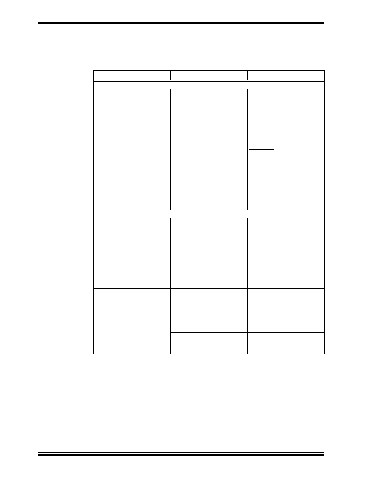
DOCUMENTATION CONVENTIONS
Description Represents Examples
Arial font:
Italic characters Referenced books MPLAB
Emphasized text ...is the only compiler...
Initial caps A window the Output window
A dialog the Settings dialog
A menu selection select Enable Programmer
Quotes A field name in a window or
dialog
Underlined, italic text with
right angle bracket
Bold characters A dialog button Click OK
N‘Rnnnn A number in verilog format,
Text in angle brackets < > A key on the keyboard Press <Enter>, <F1>
Courier New font:
Plain Courier New Sample source code #define START
Italic Courier New A variable argument file.o, where file can be
Square brackets [ ] Optional arguments mcc18 [options] file
Curly brackets and pipe
character: { | }
Ellipses... Replaces repeated text var_name [,
A menu path File>Save
A tab Click the Power tab
where N is the total number of
digits, R is the radix and n is a
digit.
Filenames autoexec.bat
File paths c:\mcc18\h
Keywords _asm, _endasm, static
Command-line options -Opa+, -Opa-
Bit values 0, 1
Constants 0xFF, ‘A’
Choice of mutually exclusive
arguments; an OR selection
Represents code supplied by
user
“Save project before build”
4‘b0010, 2‘hF1
any valid filename
[options]
errorlevel {0|1}
var_name...]
void main (void)
{ ...
}
®
IDE User’s Guide
DS50002364A-page 8 2015 Microchip Technology Inc.
Page 9

RECOMMENDED READING
This user's guide describes how to use MCP1663 9V/12V/24V Output Boost Regulator
Evaluation Board. Another useful document is listed below. The following Microchip
document is available and recommended as a supplemental reference resource.
• MCP1663 Data Sheet - “High-Voltage Integrated Switch PWM Boost
Regulator with UVLO” (DS20005406)
THE MICROCHIP WEB SITE
Microchip provides online support via our web site at www.microchip.com. This web
site is used as a means to make files and information easily available to customers.
Accessible by using your favorite Internet browser, the web site contains the following
information:
• Product Support – Data sheets and errata, application notes and sample
programs, design resources, user’s guides and hardware support documents,
latest software releases and archived software
• General Technical Support – Frequently Asked Questions (FAQs), technical
support requests, online discussion groups, Microchip consultant program
member listing
• Business of Microchip – Product selector and ordering guides, latest Microchip
press releases, listing of seminars and events, listings of Microchip sales offices,
distributors and factory representatives
Preface
CUSTOMER SUPPORT
Users of Microchip products can receive assistance through several channels:
• Distributor or Representative
• Local Sales Office
• Field Application Engineer (FAE)
• Technical Support
Customers should contact their distributor, representative or field application engineer
(FAE) for support. Local sales offices are also available to help customers. A listing of
sales offices and locations is included in the back of this document.
Technical support is available through the web site at:
http://www.microchip.com/support.
DOCUMENT REVISION HISTORY
Revision A (May 2015)
• Initial Release of this Document.
2015 Microchip Technology Inc. DS50002364A-page 9
Page 10

MCP1663 9V/12V/24V Output Boost Regulator Evaluation Board User’s Guide
NOTES:
DS50002364A-page 10 2015 Microchip Technology Inc.
Page 11

BOOST REGULATOR EVALUATION
Chapter 1. Product Overview
1.1 INTRODUCTION
This chapter provides an overview of the MCP1663 9V/12V/24V Output Boost
Regulator Evaluation Board and covers the following topics:
• MCP1663 Short Overview
• What is the MCP1663 9V/12V/24V Output Boost Regulator Evaluation Board?
• What the MCP1663 9V/12V/24V Output Boost Regulator Evaluation Board
Contains
1.2 MCP1663 DEVICE OVERVIEW
The MCP1663 is a compact, high-efficiency, fixed-frequency, non-synchronous step-up
DC/DC converter which integrates a 36V, 400 m switch. This product provides a
space-efficient high voltage step-up, easy-to-use power supply solution. The MCP1663
was developed for applications powered by two-cell or three-cell alkaline, Energizer
Lithium Primary, Ni-Cd, Ni-MH batteries, or Li-Ion or Li-Polymer batteries.
The MCP1663 operates in Pulse-Width Modulation (PWM), at a fixed 500 kHz
switching frequency. The device features an under-voltage lockout (UVLO) which
prevents fault operation below 1.85V (UVLO
discharged batteries. The MCP1663 starts its normal operation at 2.3V input voltage
(UVLO
For standby applications, MCP1663 can be put in Shutdown by pulling the EN pin to
GND. The device will stop switching and will consume a few µA of input current
(including feedback divider current; the device consumes 300 nA typical). In the Boost
configuration, the input voltage will be bypassed to output through the inductor and
Schottky diode.
MCP1663 also provides over-voltage protection (OVP) in the event of:
• Short-circuit of the feedback pin to GND
• Disconnected feedback divider
In these conditions, the OVP function will stop the internal driver and prevent damage
to the device. This feature is disabled during the start-up sequence and Thermal
Shutdown state.
The goal of the MCP1663 9V/12V/24V Output Boost Regulator Evaluation Board is to
demonstrate the higher output voltage and output current capabilities of the MCP1663
Boost Converter.
) and the operating input voltage ranges from 2.4V to 5.5V.
START
MCP1663 9V/12V/24V OUTPUT
BOARD USER’S GUIDE
®
) corresponding to the value of two
STOP
2015 Microchip Technology Inc. DS50002364A-page 11
Page 12

MCP1663 9V/12V/24V Output Boost Regulator Evaluation Board User’s Guide
µ
V
IN
EN
GND
V
FB
SW
V
IN
2.4V - 3.2V
V
OUT
12V, >100 mA
C
OUT
10 µF
C
IN
10 µF
L
4.7
µH
+
1.05 M
120 k
2X ALKALINE BATTERIES
+
-
OFF
ON
-
D
R
T
R
B
20V, 500 mA
FIGURE 1-1: Typical MCP1663 Boost Converter Two Alkaline Cells Input.
1.2.1 HIGH INPUT VOLTAGE CONFIGURATION
The MCP1663 9V/12V/24V Output Boost Regulator Evaluation Board comes with two
additional configurations that can be used to extend and overcome the typical low V
voltage range, providing significantly more flexibility for applications powered from a
higher input. The MCP1663 high-input voltage boost converter (the bottom circuit on
the evaluation board) comes with two different solutions that can be used to extend the
application's input voltage range beyond its typical values. For this circuit, V
represents the voltage applied between the VIN and GND test points on the board and
V
represents the voltage that will be present on the MCP1663 input pin.
DD
• The first option used for driving the MCP1663’s low input (V
) voltage internal
DD
circuitry is to use a linear dropout regulator (LDO) to step-down the application
supply voltage (V
• The second solution to limit the V
) to 5V.
IN
voltage is to use a Zener diode regulator.
IN
The MCP1663 low input quiescent current keeps the LDO and the Zener diode circuitry
power losses at a low level.
IN
IN
DS50002364A-page 12 2015 Microchip Technology Inc.
Page 13

Product Overview
V
IN
EN
GND
V
FB
SW
V
OUT
24V, 350 - 500 mA
C
IN
10 µF
169 k
9.1 k
R
T
R
B
GND
+
-
V
OUT
GND
+
-
MCP1663
MBRA140T3G
V
IN
9V - 16V
V
IN
D
C
OUT
2 x10 µF
L
10
µH
ZENER
LDO
BIAS
BIAS
V
IN
9V - 16V
BIAS OPTION SELECT
FIGURE 1-2: MCP1663 24V Output Boost from HV Input (9V-16V).
1.3 WHAT IS THE MCP1663 9V/12V/24V OUTPUT BOOST REGULATOR EVALUATION BOARD?
The MCP1663 9V/12V/24V Output Boost Regulator Evaluation Board is used to
evaluate and demonstrate Microchip Technology’s MCP1663 Switching Boost
Regulator. This board demonstrates the MCP1663 capabilities in two different
applications:
• 9V or 12V selectable output Boost Converter application supplied from an
external voltage source (V
typical step-up configuration is meant to highlight the MCP1663 basic boost
operation.
• 24V Output Boost converter application supplied from high voltage input rail (e.g.
9V - 16V). This application provides solutions for the particular situation in which
the required input voltage is outside the typical operating range (e.g. V
boost to 24V
Output). J1 jumper is used to choose between stepping down the VIN
voltage using the LDO or the Zener diode circuitry.
The board can be used to evaluate the SOT-23-5 lead package. The MCP1663
1.4 WHAT THE MCP1663 9V/12V/24V OUTPUT BOOST REGULATOR EVALUATION BOARD KIT CONTAINS
9V/12V/24V Output Boost Regulator Evaluation Board was developed to help
engineers reduce product design cycle time.
The output voltage is set to the proper value using an external resistor divider, resulting
in a simple and compact solution.
This MCP1663 9V/12V/24V Output Boost Regulator Evaluation Board kit includes:
• MCP1663 9V/12V/24V Output Boost Regulator Evaluation Board (ADM00664)
• Information Sheet
< 5.5V e.g. Li-Ion cell boost to 9V or 12V). This
IN
IN
= 12V
2015 Microchip Technology Inc. DS50002364A-page 13
Page 14

MCP1663 9V/12V/24V Output Boost Regulator Evaluation Board User’s Guide
NOTES:
DS50002364A-page 14 2015 Microchip Technology Inc.
Page 15

Chapter 2. Installation and Operation
2.1 INTRODUCTION
MCP1663 is a non-synchronous, fixed-frequency step-up DC/DC converter which has
been developed for applications that require higher output voltage capabilities.
MCP1663 can regulate the output voltage up to 32V and can deliver up to 250 mA load
at 3.3V input and 12V output (see Figure 2-3). At light loads, MCP1663 skips pulses to
keep the output ripple low. The regulated output voltage (V
the input voltage (V
Another important feature is that the device integrates the compensation and protection
circuitry, such that the final solution lowers total system cost, eases implementation and
requires a minimum number of additional components and board area.
2.1.1 MCP1663 9V/12V/24V Output Boost Regulat or Evaluation Board
The MCP1663 9V/12V/24V Output Boost Regulator Evaluation Board has the
following features:
• MCP1663 device can be evaluated in two separate applications:
Typical 9V/12V Output supplied from low-input voltage source
- Input Voltage range (V
- Output Current: typical 250 mA @ 12V Output, 3.3V Input
- Enable state selectable using EN switch
24V Output supplied from high input voltage source
- Input Voltage range (V
• Undervoltage Lockout (UVLO)
- UVLO Start: 2.3V
- UVLO Stop: 1.85V
• PWM Operation
• PWM Switching Frequency: 500 kHz
• Peak Input Current Limit of 1.8A (typical)
• Internal Compensation
•Soft Start
• Protection in case of feedback pin shorted to GND
• Overtemperature Protection (if the die temperature exceeds +150°C, with 15°C
hysteresis)
MCP1663 9V/12V/24V OUTPUT
BOOST REGULATOR EVALUATION
BOARD USER’S GUIDE
) should be greater than
V
OUT
OUT
Features
IN
).
): 2.4V to 5.5V, with V
IN
): 9V to 16V
IN
IN
2015 Microchip Technology Inc. DS50002364A-page 15
Page 16

MCP1663 9V/12V/24V Output Boost Regulator Evaluation Board User’s Guide
V
IN
EN
GND
V
FB
SW
V
OUT
9V, 12V selectable
C
OUT
10 µF
C
IN
10 µF
L
1
4.7
µH
1.1 M
174 k
R
T1
R
B1
GND
+
-
V
OUT
GND
+
-
MCP1663
40V, 1A
V
IN
2.4V to 5.5V
V
IN
D5
SW3
453 k
R
B2
V
IN
EN
GND
V
FB
SW
V
OUT
24V
C
4
10 µF
169 k
9.1 k
R
T
R
B
GND
+
-
V
OUT
GND
+
-
MCP1663
40V, 1A
V
IN
9V - 16V
V
IN
D4
V
IN
SHDN
GND
V
OUT
MCP1804/5V
C
1
1µF
C
1
1µF
D1
D2
C
1
1µF
D
Z
5.1V
5.6 k
R
1
5.6 k
R
2
J1
V
IN
DZ
IN
C
8
10 µF
DZ
IN
L
2
10
µH
C
5
10 µF
C
9
0.1 µF
V
DD
V
DD
FIGURE 2-1: MCP1663 Evaluation Board Schematic.
DS50002364A-page 16 2015 Microchip Technology Inc.
Page 17

2.2 GETTING STARTED
The MCP1663 9V/12V/24V Output Boost Regulator Evaluation Board is fully
assembled and tested to evaluate and demonstrate the MCP1663 product. This board
requires the use of external laboratory supplies and load.
2.2.1 Power Input and Output Connection
2.2.1.1 POWERING THE MCP1663 9V/12V/24V OUTPUT BOOST REGULATOR
EVALUATION BOARD
The MCP1663 9V/12V/24V Output Boost Regulator Evaluation Board was designed
to be used to evaluate the MCP1663 device. The package selected is SOT-23.
Soldered test points are available for input voltage connections.
Soldered test points are available to connect a load. The switch peak current limit will
provide a safe maximum current value. The maximum output current for the converter
will vary with input and output voltages; refer to Figure 2-3 or the MCP1663 data sheet
for more information on the maximum output current.
2.2.1.2 BOARD POWER-UP PROCEDURE
TOP CIRCUIT
1. Connect the input supply as shown in Figure 2-2. The input voltage should not
be higher than 5.5V.
2. Connect system load to V
input and output voltage. Connect the (+) side of the load to V
negative (-) load to ground (GND).
3. The “VOUT SELECT” switch can be used to modify the output voltage between
two values:
- 9V, when the switch is in OFF position
- 12V, when the switch is in ON position
BOTTOM CIRCUIT
1. Connect the input supply as shown in Figure 2-2.
2. The MCP1663 can be used in the extended input voltage range 9V - 16V.
3. Connect system load to V
input and output voltage. Typically, the MCP1663 can supply a 24V output with
500 mA from a 12V input source at room temperature. Connect the (+) side of
the load to V
4. There are two distinct methods that can be used to extend the input voltage
range:
- Using an LDO to provide the necessary low voltage (V
in “LDO” position)
- Using a Zener diode (jumper on J1 in “Zener” position)
Installation and Operation
and GND terminals; maximum load varies with
OUT
and GND terminals; maximum load varies with
OUT
and the negative (-) load to ground (GND).
OUT
and the
OUT
) bias (jumper on J1
DD
2015 Microchip Technology Inc. DS50002364A-page 17
Page 18

MCP1663 9V/12V/24V Output Boost Regulator Evaluation Board User’s Guide
POWER +
SUPPLY -
POWER +
SUPPLY -
V - m e t e r
V - m e t e r
V - m e t e r
+
Electronic
Load/
Resistive
Load
-
+
Electronic
Load/
Resistive
Load
-
V - m e t e r
+
Electronic
Load/
Resistive
Load
-
BIAS Supply Option Select
V
OUT
Select Switch
RT RB
V
OUT
V
FB
------------ -
1–
=
Where: V
FB
= 1.227V
FIGURE 2-2: MCP1663 9V/12V/24V Output Boost Regulator Evaluation Board Setup.
DS50002364A-page 18 2015 Microchip Technology Inc.
2.2.1.3 ADJUSTABLE V
The top circuit comes with the output value set to 9V and 12V (V
SETTING
OUT
selective using a
OUT
switch). If a different output is desired, set the switch in the OFF state (button down)
and recalculate the resistor divider (RT1 and RB1) using Equation 2-1.
The Bottom circuit comes with V
set to 24V. As in the previous case, the same
OUT
equation can be used to calculate RT and RB and set another output voltage. Note that
V
IN
EQUATION 2-1:
must be lower than V
OUT
.
Page 19

Installation and Operation
0
100
200
300
400
500
600
700
800
2.3 2.7 3.1 3.5 3.9 4.3 4.7 5.1 5.5
I
OUT
(mA)
VIN(V)
V
OUT
= 12V
V
OUT
= 9.0V
TA= 25°C
For output voltages higher than 15V, the inductor value should be increased. See
Ta bl e 2 - 1 for more information.
TABLE 2-1: RECOMMENDED RESISTOR DIVIDER AND INDUCTOR VALUES
V
OUT
6.0V 4.7 µH 1050 kΩ 270 kΩ
9.0V 4.7 µH 1000 kΩ 160 kΩ
12V 4.7 µH 1050 kΩ 120 kΩ
24V 10 µH 1050 kΩ 56 kΩ
32V 10 µH 1100 kΩ 43 kΩ
Inductor Value RT RB
2.3 TEST RESULTS FOR TYPICAL APPLICATION USING MCP1663
2.3.1 Test Results for MCP1663 - TOP Circuit
This chapter provides specific operation waveforms and graphs. Refer to the MCP1663
Data Sheet (DS20005406) for more information.
FIGURE 2-3: MCP1663 Boost - 9V and 12.0 V
Maximum 5% Output Drop.
2015 Microchip Technology Inc. DS50002364A-page 19
Maximum I
OUT
vs. VIN with
OUT
Page 20

MCP1663 9V/12V/24V Output Boost Regulator Evaluation Board User’s Guide
20
30
40
50
60
70
80
90
100
0.1 1 10 100 1000
V
OUT
= 9.0V
VIN= 3.0V
VIN= 2.3V
VIN= 4.0V
VIN= 5.5V
20
30
40
50
60
70
80
90
100
0.1 1 10 100 1000
V
OUT
= 12.0V
VIN= 4.0V
VIN= 5.5V
VIN= 3.0V
VIN= 2.3V
Efficiency (%)
I
(mA)
OUT
FIGURE 2-4: MCP1663 9V Output Efficiency vs. I
Efficiency (%)
I
(mA)
OUT
FIGURE 2-5: MCP1663 12V Output Efficiency vs. I
OUT
OUT
.
.
DS50002364A-page 20 2015 Microchip Technology Inc.
Page 21

Installation and Operation
V
OUT
50 mV/div, AC Coupled
20 MHz BW
I
L
500 mA/div
10 V/div
I
OUT
= 500 mA
2µs/div
VIN 12V
V
SW
0
200
400
600
800
6 8 10 12 14
I
OUT
(mA)
VIN(V)
V
OUT
= 24V
TA= 25°C
Note: VDD = 4.5V
2.3.2 Test Results for MCP1663 - BOTTOM Circuit
The second circuit was developed for applications where an input voltage higher than
the typical working range is needed. Refer to Figure 2-7 for the maximum output
current that can be obtained for different input voltages.
FIGURE 2-6: MCP1663 24.0V V
FIGURE 2-7: MCP1663 Maximum I
OUT
High Load Operation Waveforms.
vs. VIN.
OUT
2015 Microchip Technology Inc. DS50002364A-page 21
Page 22

MCP1663 9V/12V/24V Output Boost Regulator Evaluation Board User’s Guide
80
82
84
86
88
90
92
94
96
0 100 200 300 400 500 600 700
Efficiency (%)
I
OUT
(mA)
VIN= 9V
VIN= 12V
VIN= 15V
V
OUT
= 24V
Note: VDD = 4.5V
FIGURE 2-8: MCP1663 Efficiency vs. I
2.4 BATTERY CONSIDERATIONS
When considering a power solution for a design, the battery needs to be carefully
selected. Alkaline batteries are a commonly available option that delivers good
performance in a variety of applications. Energizer
alternative power solution that provide superior-performance high drains and allows
designers to utilize the full power range of the MCP1663 without sacrificing size or
runtime.
Energizer Ultimate Lithium batteries utilize a primary cell chemistry that contain higher
energy than alkaline batteries, and have much better high drain performance. Ultimate
Lithium batteries produce a high, flat voltage profile that enables them to provide a high
energy capacity even at high drains. Additionally, Ultimate Lithium batteries have a very
low internal resistance, allowing them to maintain a high voltage at very high loads.
.
OUT
®
Ultimate Lithium batteries are an
DS50002364A-page 22 2015 Microchip Technology Inc.
Page 23

Appendix A. Schematic and Layouts
A.1 INTRODUCTION
This appendix contains the following schematics and layouts for the MCP1663
9V/12V/24V Output Boost Regulator Evaluation Board:
• Board – Schematic
• Board – Top Silk And Pads
• Board – Top Silk And Copper
• Board – Top Copper
• Board – Bottom Copper
MCP1663 9V/12V/24V OUTPUT
BOOST REGULATOR EVALUATION
BOARD USER’S GUIDE
2015 Microchip Technology Inc. DS50002364A-page 23
Page 24

MCP1663 9V/12V/24V Output Boost Regulator Evaluation Board User’s Guide
SW2
GND2 GND2 GND2
IN
GND2
VIN
GND2
VIN
IN
GND1
GND1
GND1
GND1
VOUT
SW
1
GND
2
FB
3
VIN
5
EN
4
D
FBVIN
EN
MCP1663
U3
TP1
TP2
TP3
TP4
TP5
TP6
TP7 TP8
TP9
1
J11
VIN
1
J13
GND
1
J12
VOUT
1
J14
GND
1
J3
VIN
1
J6
GND
1
J5
VOUT
1
J7
GND
10uF
C6
10uF
C4
10uF
C5
10uF
C8
1uF
C1
1uF
C2
VIN
1
GND
2
SHDN
4
NC
3
VOUT
5
MCP1804/5V
U1
SW
1
GND
2
FB
3
VIN
5
EN
4
D
FBVIN
EN
MCP1663
U2
4.7uH
L1
1.1M
RT1
174k
RB1
SW3
MBRA140T3G
D5
MBRA140T3G
D4
169k
RT
9.1k
RB
1N4148
D1
1N4148
D2
5.1V
D3
5.6K
R2
5.6K
R1
1
2
3
J1
453k
RB2
0.1uF
C9
GND2
10uF
C7
10uF
C3
10uH
L2
V
DD
V
DD
A.2 BOARD – SCHEMATIC
SW1
W
N
GND2
N
GND2 GND2GND2
DS50002364A-page 24 2015 Microchip Technology Inc.
Page 25

A.3 BOARD – TOP SILK AND PADS
Schematic and Layouts
2015 Microchip Technology Inc. DS50002364A-page 25
Page 26

MCP1663 9V/12V/24V Output Boost Regulator Evaluation Board User’s Guide
A.4 BOARD – TOP SILK AND COPPER
DS50002364A-page 26 2015 Microchip Technology Inc.
Page 27

A.5 BOARD – TOP COPPER
Schematic and Layouts
2015 Microchip Technology Inc. DS50002364A-page 27
Page 28

MCP1663 9V/12V/24V Output Boost Regulator Evaluation Board User’s Guide
A.6 BOARD – BOTTOM COPPER
DS50002364A-page 28 2015 Microchip Technology Inc.
Page 29

MCP1663 9V/12V/24V OUTPUT
BOOST REGULATOR EVALUATION
BOARD USER’S GUIDE
Appendix B. Bill of Materials (BOM)
TABLE B-1: BILL OF MATERIALS (BOM)
Qty. Reference Description Manufacturer Part Number
1 C1 Cap. ceramic 1 µF 35V 10% X7R SMD
0805
1 C2 Cap. ceramic 1 µF 10V 20% X7R SMD
0603
2 C3, C7 Cap. ceramic 10 µF 16V 20% X5R SMD
0805
4 C4, C5, C6, C8Cap. ceramic 10 µF 50V 20% X7S SMD
1210
1 C9 Cap. ceramic 0.1 µF 50V 20% X7R SMD
0603
2 D1, D2 Diode rectifier 1N4148 855 mV 150 mA
75V SOD-323
1 D3 Diode Zener 1SMA5918BT3G 5.1V 1.5W
DO-214AC_SMA
2 D4, D5 Diode Schottky MBRA140T3G 550 mV
1A 40V DO-214AC_SMA
1 J1 Conn. header-2.54 Male 1x3 tin 5.84 MH
th. vert.
8 J3, J5, J6,
J7, J11, J12,
J13, J14
1 JP1 Mech. hardware jumper 2.54 mm
1 L1 Inductor 4.7 µH 2A 20% SMD XFL4020 Coilcraft XFL4020-472MEB
1 L2 Inductor 10 µH 2.2A 20% SMD
4PAD1,
PAD 2,
PAD 3, PAD 4
2 R1, R2 Resistor 5.6K Ohm 1/4W 1% 1206 SMD Panasonic
1 RB Resistor TKF 9.1k 1% 1/8W SMD 0805 Panasonic Electronic
1 RB1 Resistor TKF 174k 1% 1/8W SMD 0805 Panasonic Electronic
1 RB2 Resistor TKF 453k 1% 1/8W SMD 0805 Panasonic Electronic
1 RT Resistor TKF 169k 1% 1/8W SMD 0805 Panasonic Electronic
Note 1: The components listed in this Bill of Materials are representative of the PCB assembly. The released
Conn. TP loop tin SMD Harwin Plc S1751-46R
1x2 handle gold
L4.3W4.3H4.1
Mech. hardware rubber pad Bumpon
Hemisphere 0.630" x 0.312" black
BOM used in manufacturing uses all RoHS-compliant components.
TDK Corporation CGA4J3X7R1V105K125AB
TDK Corporation C1608X7R1A105M
TDK Corporation C2012X5R1C106M/0.85
TDK Corporation C3225X7S1H106M
TDK Corporation C1608X7R1H104M
®
Diodes
ON Semiconductor
ON Semiconductor MBRA140T3G
Samtec, Inc. TSW-103-07-T-S
TE Connectivity 881545-2
Coilcraft XAL4040-103MEB
3M SJ-5027 (BLACK)
Components Group
Components Group
Components Group
Components Group
Components Group
Incorporated 1N4148WS-7
®
1SMA5918BT3G
®
Electronic
ERJ-8ENF5601V
ERJ-6ENF9101V
ERJ-6ENF1743V
ERJ-6ENF4533V
ERJ-6ENF1693V
2015 Microchip Technology Inc. DS50002364A-page 29
Page 30

Bill of Materials (BOM)
TABLE B-1: BILL OF MATERIALS (BOM) (CONTINUED)
Qty. Reference Description Manufacturer Part Number
1 RT1 Resistor TKF 1.1M 1% 1/8W SMD 0805 Panasonic Electronic
Components Group
1 SW3 Switch dip. spst. 24V 25 mA
418121270801 SMD
9TP1, TP2,
TP3, TP4,
TP5, TP6,
TP7, TP8,
TP9
1 U1 Microchip analog LDO 5V
2 U2, U3 Microchip analog switcher boost 24V
Note 1: The components listed in this Bill of Materials are representative of the PCB assembly. The released
Conn. TP loop red th. Keystone Electronics
MCP1804T-5002I/OT SOT-23-5
MCP1663T-E/OT SOT-23-5
BOM used in manufacturing uses all RoHS-compliant components.
Wurth Electronik Group 418121270801
Corp.
Microchip Technology
Inc.
Microchip Technology
Inc.
ERJ-6ENF1104V
5010
MCP1804T-5002I/OT
MCP1663T-E/OT
2015 Microchip Technology Inc. DS50002364A-page 30
Page 31

NOTES:
Bill of Materials (BOM)
2015 Microchip Technology Inc. DS50002364A-page 31
Page 32

Worldwide Sales and Service
AMERICAS
Corporate Office
2355 West Chandler Blvd.
Chandler, AZ 85224-6199
Tel: 480-792-7200
Fax: 480-792-7277
Technical Support:
http://www.microchip.com/
support
Web Address:
www.microchip.com
Atlanta
Duluth, GA
Tel: 678-957-9614
Fax: 678-957-1455
Austin, TX
Tel: 512-257-3370
Boston
Westborough, MA
Tel: 774-760-0087
Fax: 774-760-0088
Chicago
Itasca, IL
Tel: 630-285-0071
Fax: 630-285-0075
Cleveland
Independence, OH
Tel: 216-447-0464
Fax: 216-447-0643
Dallas
Addison, TX
Tel: 972-818-7423
Fax: 972-818-2924
Detroit
Novi, MI
Tel: 248-848-4000
Houston, TX
Tel: 281-894-5983
Indianapolis
Noblesville, IN
Tel: 317-773-8323
Fax: 317-773-5453
Los Angeles
Mission Viejo, CA
Tel: 949-462-9523
Fax: 949-462-9608
New Yor k , NY
Tel: 631-435-6000
San Jose, CA
Tel: 408-735-9110
Canada - Toronto
Tel: 905-673-0699
Fax: 905-673-6509
ASIA/PACIFIC
Asia Pacific Office
Suites 3707-14, 37th Floor
Tower 6, The Gateway
Harbour City, Kowloon
Hong Kong
Tel: 852-2943-5100
Fax: 852-2401-3431
Australia - Sydney
Tel: 61-2-9868-6733
Fax: 61-2-9868-6755
China - Beijing
Tel: 86-10-8569-7000
Fax: 86-10-8528-2104
China - Chengdu
Tel: 86-28-8665-5511
Fax: 86-28-8665-7889
China - Chongqing
Tel: 86-23-8980-9588
Fax: 86-23-8980-9500
China - Dongguan
Tel: 86-769-8702-9880
China - Hangzhou
Tel: 86-571-8792-8115
Fax: 86-571-8792-8116
China - Hong Kong SAR
Tel: 852-2943-5100
Fax: 852-2401-3431
China - Nanjing
Tel: 86-25-8473-2460
Fax: 86-25-8473-2470
China - Qingdao
Tel: 86-532-8502-7355
Fax: 86-532-8502-7205
China - Shanghai
Tel: 86-21-5407-5533
Fax: 86-21-5407-5066
China - Shenyang
Tel: 86-24-2334-2829
Fax: 86-24-2334-2393
China - Shenzhen
Tel: 86-755-8864-2200
Fax: 86-755-8203-1760
China - Wuhan
Tel: 86-27-5980-5300
Fax: 86-27-5980-5118
China - Xian
Tel: 86-29-8833-7252
Fax: 86-29-8833-7256
ASIA/PACIFIC
China - Xiamen
Tel: 86-592-2388138
Fax: 86-592-2388130
China - Zhuhai
Tel: 86-756-3210040
Fax: 86-756-3210049
India - Bangalore
Tel: 91-80-3090-4444
Fax: 91-80-3090-4123
India - New Delhi
Tel: 91-11-4160-8631
Fax: 91-11-4160-8632
India - Pune
Tel: 91-20-3019-1500
Japan - Osaka
Tel: 81-6-6152-7160
Fax: 81-6-6152-9310
Japan - Tokyo
Tel: 81-3-6880- 3770
Fax: 81-3-6880-3771
Korea - Daegu
Tel: 82-53-744-4301
Fax: 82-53-744-4302
Korea - Seoul
Tel: 82-2-554-7200
Fax: 82-2-558-5932 or
82-2-558-5934
Malaysia - Kuala Lumpur
Tel: 60-3-6201-9857
Fax: 60-3-6201-9859
Malaysia - Penang
Tel: 60-4-227-8870
Fax: 60-4-227-4068
Philippines - Manila
Tel: 63-2-634-9065
Fax: 63-2-634-9069
Singapore
Tel: 65-6334-8870
Fax: 65-6334-8850
Tai wan - Hsin Chu
Tel: 886-3-5778-366
Fax: 886-3-5770-955
Taiwan - Kaohsiung
Tel: 886-7-213-7828
Taiwan - Taipei
Tel: 886-2-2508-8600
Fax: 886-2-2508-0102
Thailand - Bangkok
Tel: 66-2-694-1351
Fax: 66-2-694-1350
EUROPE
Austria - Wels
Tel: 43-7242-2244-39
Fax: 43-7242-2244-393
Denmark - Copenhagen
Tel: 45-4450-2828
Fax: 45-4485-2829
France - Paris
Tel: 33-1-69-53-63-20
Fax: 33-1-69-30-90-79
Germany - Dusseldorf
Tel: 49-2129-3766400
Germany - Munich
Tel: 49-89-627-144-0
Fax: 49-89-627-144-44
Germany - Pforzheim
Tel: 49-7231-424750
Italy - Milan
Tel: 39-0331-742611
Fax: 39-0331-466781
Italy - Venice
Tel: 39-049-7625286
Netherlands - Drunen
Tel: 31-416-690399
Fax: 31-416-690340
Poland - Wars a w
Tel: 48-22-3325737
Spain - Madrid
Tel: 34-91-708-08-90
Fax: 34-91-708-08-91
Sweden - Stockholm
Tel: 46-8-5090-4654
UK - Wokingham
Tel: 44-118-921-5800
Fax: 44-118-921-5820
01/27/15
DS50002364A-page 32 2015 Microchip Technology Inc.
Page 33

Mouser Electronics
Authorized Distributor
Click to View Pricing, Inventory, Delivery & Lifecycle Information:
Microchip:
ADM00664
 Loading...