

Page 1
MCP1630
Input Boost Converter
Demo Board
User’s Guide
© 2007 Microchip Technology Inc. DS51608B
Page 2
Note the following details of the code protection feature on Microchip devices:
• Microchip products meet the specification contained in their particular Microchip Data Sheet.
• Microchip believes that its family of products is one of the most secure families of its kind on the market today, when used in the
intended manner and under normal conditions.
• There are dishonest and possibly illegal methods used to breach the code protection feature. All of these methods, to our
knowledge, require using the Microchip products in a manner outside the operating specifications contained in Microchip’s Data
Sheets. Most likely, the person doing so is engaged in theft of intellectual property.
• Microchip is willing to work with the customer who is concerned about the integrity of their code.
• Neither Microchip nor any other semiconductor manufacturer can guarantee the security of their code. Code protection does not
mean that we are guaranteeing the product as “unbreakable.”
Code protection is constantly evolving. We at Microchip are committed to continuously improving the code protection features of our
products. Attempts to break Microchip’s code protection feature may be a violation of the Digital Millennium Copyright Act. If such acts
allow unauthorized access to your software or other copyrighted work, you may have a right to sue for relief under that Act.
Information contained in this publication regarding device
applications and the like is provided only for your convenience
and may be superseded by updates. It is your responsibility to
ensure that your application meets with your specifications.
MICROCHIP MAKES NO REPRESENTATIONS OR
WARRANTIES OF ANY KIND WHETHER EXPRESS OR
IMPLIED, WRITTEN OR ORAL, STATUTORY OR
OTHERWISE, RELATED TO THE INFORMATION,
INCLUDING BUT NOT LIMITED TO ITS CONDITION,
QUALITY, PERFORMANCE, MERCHANTABILITY OR
FITNESS FOR PURPOSE. Microchip disclaims all liability
arising from this information and its use. Use of Microchip
devices in life support and/or safety applications is entirely at
the buyer’s risk, and the buyer agrees to defend, indemnify and
hold harmless Microchip from any and all damages, claims,
suits, or expenses resulting from such use. No licenses are
conveyed, implicitly or otherwise, under any Microchip
intellectual property rights.
Trademarks
The Microchip name and logo, the Microchip logo, Accuron,
dsPIC, K
EELOQ, KEELOQ logo, microID, MPLAB, PIC,
PICmicro, PICSTART, PRO MATE, rfPIC and SmartShunt are
registered trademarks of Microchip Technology Incorporated
in the U.S.A. and other countries.
AmpLab, FilterLab, Linear Active Thermistor, Migratable
Memory, MXDEV, MXLAB, SEEVAL, SmartSensor and The
Embedded Control Solutions Company are registered
trademarks of Microchip Technology Incorporated in the
U.S.A.
Analog-for-the-Digital Age, Application Maestro, CodeGuard,
dsPICDEM, dsPICDEM.net, dsPICworks, ECAN,
ECONOMONITOR, FanSense, FlexROM, fuzzyLAB,
In-Circuit Serial Programming, ICSP, ICEPIC, Mindi, MiWi,
MPASM, MPLAB Certified logo, MPLIB, MPLINK, PICkit,
PICDEM, PICDEM.net, PICLAB, PICtail, PowerCal,
PowerInfo, PowerMate, PowerTool, REAL ICE, rfLAB, Select
Mode, Smart Serial, SmartTel, Total Endurance, UNI/O,
WiperLock and ZENA are trademarks of Microchip
Technology Incorporated in the U.S.A. and other countries.
SQTP is a service mark of Microchip Technology Incorporated
in the U.S.A.
All other trademarks mentioned herein are property of their
respective companies.
© 2007, Microchip Technology Incorporated, Printed in the
U.S.A., All Rights Reserved.
Printed on recycled paper.
Microchip received ISO/TS-16949:2002 certification for its worldwide
headquarters, design and wafer fabrication facilities in Chandler and
Tempe, Arizona; Gresham, Oregon and design centers in California
and India. The Company’s quality system processes and procedures
are for its PIC
devices, Serial EEPROMs, microperipherals, nonvolatile memory and
analog products. In addition, Microchip’s quality system for the design
and manufacture of development systems is ISO 9001:2000 certified.
®
MCUs and dsPIC® DSCs, KEELOQ
®
code hopping
DS51608B-page ii © 2007 Microchip Technology Inc.
Page 3

MCP1630 AUTOMOTIVE INPUT BOOST
CONVERTER DEMO BOARD USER’S GUIDE
Table of Contents
Preface ........................................................................................................................... 1
Introduction............................................................................................................ 1
Document Layout .................................................................................................. 1
Conventions Used in this Guide ............................................................................ 2
Recommended Reading........................................................................................ 2
The Microchip Web Site ........................................................................................ 3
Customer Support ................................................................................................. 3
Document Revision History................................................................................... 3
Chapter 1. Product Overview
1.1 Introduction...................................................................................................... 5
1.2 What is the MCP1630 Automotive Input Boost Converter Demo Board? ....... 6
1.3 What the MCP1630 Automotive Input Boost Converter Demo Board Kit
Includes ..................................................................................................... 6
Chapter 2. Installation and Operation
2.1 Introduction...................................................................................................... 7
2.2 Features .......................................................................................................... 7
2.3 Getting Started ................................................................................................ 8
Appendix A. Schematic and Layouts
A.1 Introduction ................................................................................................... 11
A.2 Board – Schematic........................................................................................ 12
A.3 Board – Top Silk Layer ................................................................................. 13
A.4 Board – Top Metal Layer .............................................................................. 14
A.5 Board – Bottom Metal Layer ......................................................................... 15
Appendix B. Bill Of Materials (BOM)
Appendix C. Demo Board Firmware
C.1 Device Firmware........................................................................................... 19
Worldwide Sales and Service .................................................................................... 20
© 2007 Microchip Technology Inc. DS51608B-page iii
Page 4

MCP1630 Automotive Input Boost Converter Demo Board User’s Guide
NOTES:
DS51608B-page iv © 2007 Microchip Technology Inc.
Page 5
MCP1630 AUTOMOTIVE INPUT BOOST
CONVERTER DEMO BOARD USER’S GUIDE
Preface
NOTICE TO CUSTOMERS
All documentation becomes dated, and this manual is no exception. Microchip tools and
documentation are constantly evolving to meet customer needs, so some actual dialogs
and/or tool descriptions may differ from those in this document. Please refer to our web site
(www.microchip.com) to obtain the latest documentation available.
Documents are identified with a “DS” number. This number is located on the bottom of each
page, in front of the page number. The numbering convention for the DS number is
“DSXXXXXA”, where “XXXXX” is the document number and “A” is the revision level of the
document.
For the most up-to-date information on development tools, see the MPLAB
Select the Help menu, and then Topics to open a list of available on-line help files.
INTRODUCTION
®
IDE on-line help.
This chapter contains general information that will be useful to know before using the
MCP1630 Automotive Input Boost Converter Demo Board. Items discussed in this
chapter include:
• Document Layout
• Conventions Used in this Guide
• Recommended Reading
• The Microchip Web Site
• Customer Support
• Document Revision History
DOCUMENT LAYOUT
This document describes how to use the MCP1630 Automotive Input Boost Converter
Demo Board. The manual layout is as follows:
• Chapter 1. “Product Overview” – Important information about the MCP1630
Automotive Input Boost Converter Demo Board.
• Chapter 2. “Installation and Operation” – Includes instructions on how to get
started with this user’s guide and a description of the user’s guide.
• Appendix A. “Schematic and Layouts” – Shows the schematic and layout
diagrams for the MCP1630 Automotive Input Boost Converter Demo Board.
• Appendix B. “Bill Of Materials (BOM)” – Lists the parts used to build the
MCP1630 Automotive Input Boost Converter Demo Board.
• Appendix C. “Demo Board Firmware” – Provides information about the
application firmware and where the source code can be found.
© 2007 Microchip Technology Inc. DS51608B-page 1
Page 6
MCP1630 Automotive Input Boost Converter Demo Board User’s Guide
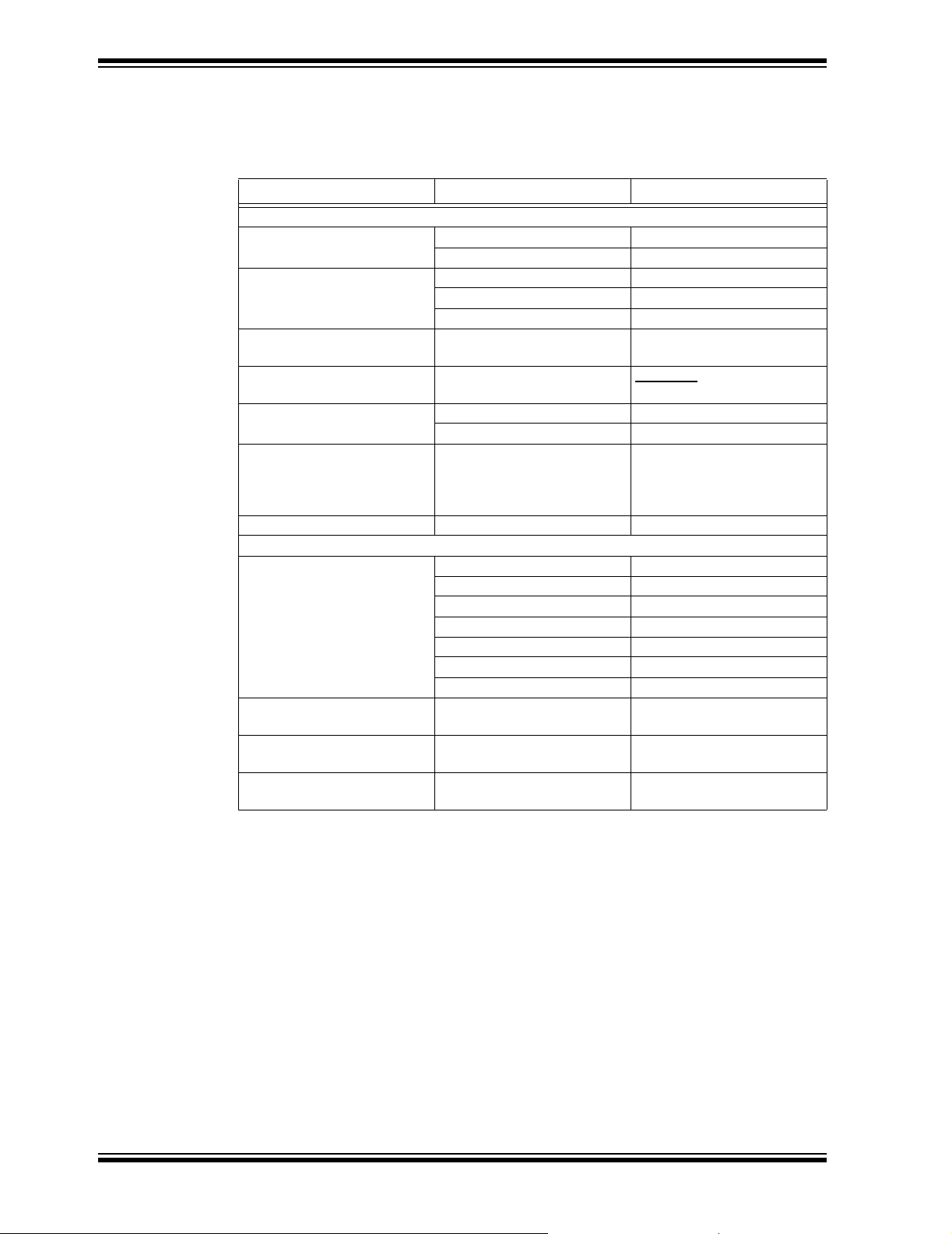
CONVENTIONS USED IN THIS GUIDE
This manual uses the following documentation conventions:
DOCUMENTATION CONVENTIONS
Description Represents Examples
Arial font:
Italic characters Referenced books MPLAB® IDE User’s Guide
Emphasized text ...is the only compiler...
Initial caps A window the Output window
A dialog the Settings dialog
A menu selection select Enable Programmer
Quotes A field name in a window or
dialog
Underlined, italic text with
right angle bracket
Bold characters A dialog button Click OK
N‘Rnnnn A number in verilog format,
Text in angle brackets < > A key on the keyboard Press <Enter>, <F1>
Courier New font:
Plain Courier New Sample source code #define START
Italic Courier New A variable argument file.o, where file can be
Square brackets [ ] Optional arguments mcc18 [options] file
Curly brackets and pipe
character: { | }
A menu path File>Save
A tab Click the Power tab
where N is the total number of
digits, R is the radix and n is a
digit.
Filenames autoexec.bat
File paths c:\mcc18\h
Keywords _asm, _endasm, static
Command-line options -Opa+, -Opa-
Bit values 0, 1
Constants 0xFF, ‘A’
Choice of mutually exclusive
arguments; an OR selection
“Save project before build”
4‘b0010, 2‘hF1
any valid filename
[options]
errorlevel {0|1}
RECOMMENDED READING
This user's guide describes how to use MCP1630 Automotive Input Boost Converter
Demo Board. The following Microchip documents are available and recommended as
supplemental reference resources.
MCP1630/MCP1630V Data Sheet, "High-Speed, Microcontroller-Adaptable, Pulse
Width Modulator" (DS21896)
This data sheet provides detailed information regarding the MCP1630/MCP1630V
product family.
PIC12F683 Data Sheet, "8-Pin Flash-Based, 8-Bit CMOS Microcontrollers with
Nano Watt Technology" (DS41211)
This data sheet provides detailed information regarding the PIC12F683 product family.
DS51608B-page 2 © 2007 Microchip Technology Inc.
Page 7

THE MICROCHIP WEB SITE
Microchip provides online support via our web site at www.microchip.com. This web
site is used as a means to make files and information easily available to customers.
Accessible by using your favorite Internet browser, the web site contains the following
information:
• Product Support – Data sheets and errata, application notes and sample
programs, design resources, user’s guides and hardware support documents,
latest software releases and archived software
• General Technical Support – Frequently Asked Questions (FAQs), technical
support requests, online discussion groups, Microchip consultant program
member listing
• Business of Microchip – Product selector and ordering guides, latest Microchip
press releases, listing of seminars and events, listings of Microchip sales offices,
distributors and factory representatives
CUSTOMER SUPPORT
Users of Microchip products can receive assistance through several channels:
• Distributor or Representative
• Local Sales Office
• Field Application Engineer (FAE)
• Technical Support
Customers should contact their distributor, representative or field application engineer
(FAE) for support. Local sales offices are also available to help customers. A listing of
sales offices and locations is included in the back of this document.
Technical support is available through the web site at: http://support.microchip.com
Preface
DOCUMENT REVISION HISTORY
Revision B (June 2007)
• Updated Bill of Materials (BOM) for C12, C13, and L1
• Add disclaimer to Bill of Materials regarding RoHS-Compliant part numbers.
Revision A (April 2006)
• Initial Release of this Document.
© 2007 Microchip Technology Inc. DS51608B-page 3
Page 8

MCP1630 Automotive Input Boost Converter Demo Board User’s Guide
NOTES:
DS51608B-page 4 © 2007 Microchip Technology Inc.
Page 9
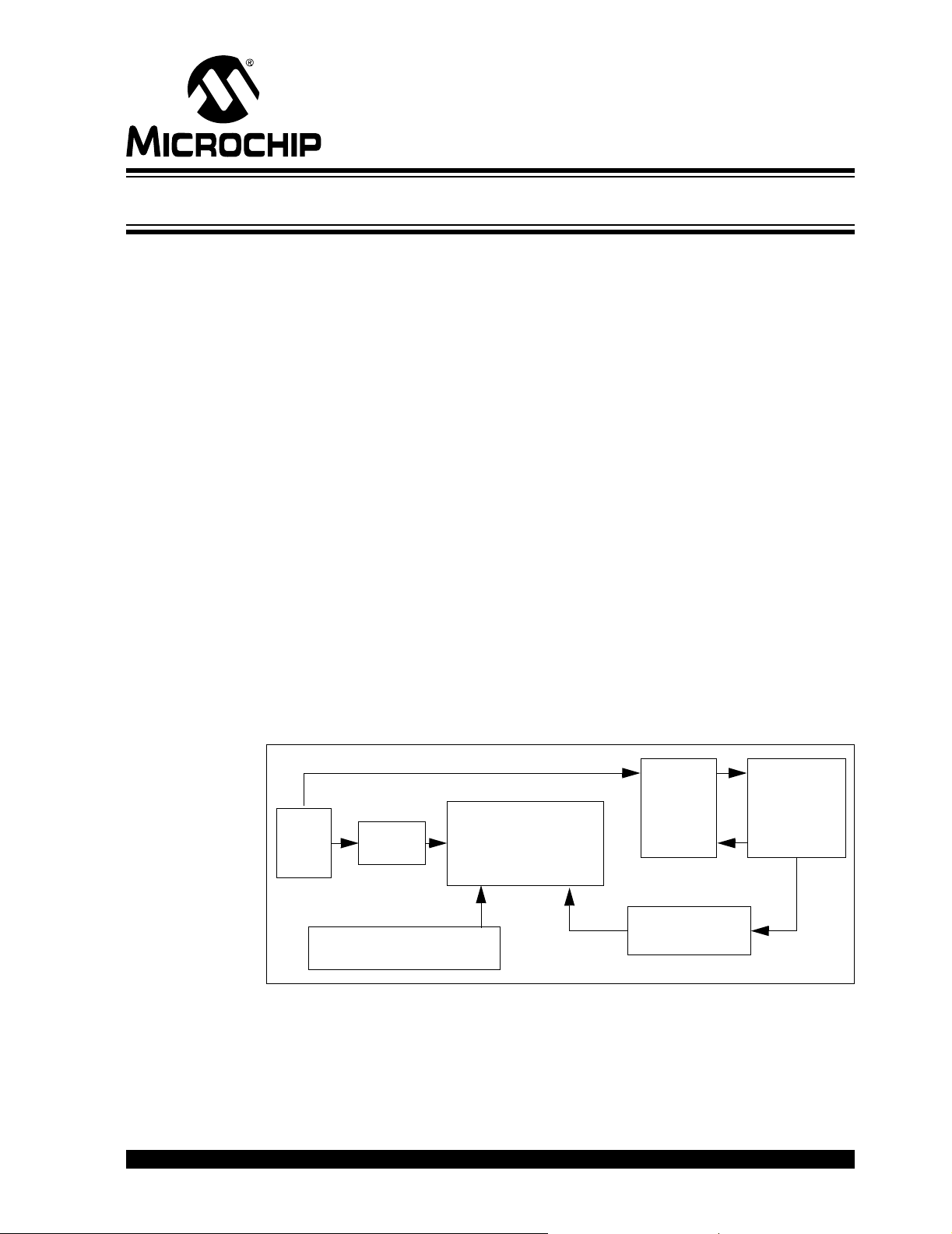
Chapter 1. Product Overview
9V-18V
Battery
Supply
MCP1630/V High-Speed,
Microcontroller-Adaptable,
Pulse Width Modulator
Boost
Converter
LOAD
36.5V / 400 mA
14.6W Max
Power
PIC12F683 for Osc Input & V
REF
Voltage
Regulator
Feedback
1.1 INTRODUCTION
The proliferation of distributed power supplies is expected to accelerate their use in
future generation cars. Distributed power supplies or "point-of-load" power supplies are
being used increasingly throughout. These Power Supply Units (PSUs) are responsible
for stepping up (or down) a 12V nominal bus, to power a multitude of subsystems.
These include telematics/navigation systems, power seats and doors, interior and
exterior lighting, electronic braking and engine management control.
Many automotive and industrial applications require higher voltages than are available
on the input power supply rail. Supply voltages required for these systems can range
from 36V (power seats and windows) to 1.8V (to drive low-voltage microprocessors).
In addition, depending on where the PSU operates on the automotive power bus, it may
be required to perform under very stringent power requirements.
Automotive subsystems with their inherent high voltage transients and high efficiency
requirements place increasing demands on power supply designs. These supplies
must provide high power, high efficiency and low noise from a very compact footprint
and must maintain a high efficiency over a wide range of operational input voltages.
The MCP1630/V high-speed, microcontroller-adaptable Pulse Width Modulator (PWM)
is capable of maintaining output regulation with no adverse effects on system
performance or reliability. The MCP1630 Automotive Input Boost Converter Demo
Board provides a better choice for automotive application design and high efficiency.
This chapter covers the following topics.
• What is the MCP1630 Automotive Input Boost Converter Demo Board?
• What the MCP1630 Automotive Input Boost Converter Demo Board Kit includes.
MCP1630 AUTOMOTIVE INPUT BOOST
CONVERTER DEMO BOARD USER’S GUIDE
© 2007 Microchip Technology Inc. DS51608B-page 5
FIGURE 1-1: MCP1630 Automotive Input Boost Converter Demo Board Block
Diagram.
Page 10

MCP1630 Automotive Input Boost Converter Demo Board User’s Guide
1.2 WHAT IS THE MCP1630 AUTOMOTIVE INPUT BOOST CONVERTER DEMO BOARD?
The MCP1630 Automotive Input Boost Converter Demo Board demonstrates the use
of a conventional boost topology with automotive input. The board also serves as a
platform to evaluate the MCP1630/V devices.
The MCP1630/V inputs were developed to be easily attached to the I/O of a
microcontroller. The Microcontroller Unit (MCU) supplies the oscillator pulses and
reference voltage (V
adaptable power system. The power system switching frequency and maximum duty
cycle are set using the I/O of the MCU. The reference input to the high-speed PWM can
be external, a D/A Converter (DAC) output or as simple as an I/O output from the MCU.
This enables the power system to adapt to many external signals and variables in order
to optimize performance and facilitate calibration.
This board utilizes Microchip's MCP1630/V (high-speed PICmicro
integrated with PIC12F683 (Flash MCU SOIC8) in automotive input application. Under
normal operation, the vehicle voltage at the supply lines ranges between 9V-18V (12V
system). The converter is capable of delivering an output voltage of 36.5V at 400 mA
load current with maximum power of 14.6W. The line and load regulation is within the
regulation band of 3%.
) to the MCP1630/V devices to provide the most flexible and
REF
®
MCU PWM)
1.3 WHAT THE MCP1630 AUTOMOTIVE INPUT BOOST CONVERTER DEMO BOARD KIT INCLUDES
This MCP1630 Automotive Input Boost Converter Demo Board kit includes:
• MCP1630 Automotive Input Boost Converter Demo Board (102-00095)
• Analog and Interface Products Demonstration Boards CD-ROM (DS21912)
- MCP1630 Automotive Input Boost Converter Demo Board User’s Guide
(DS51608)
DS51608B-page 6 © 2007 Microchip Technology Inc.
Page 11

Chapter 2. Installation and Operation
2.1 INTRODUCTION
The MCP1630 Automotive Input Boost Converter Demo Board demonstrates
Microchip's high-speed pulse width modulator used for automotive applications. When
used in conjunction with a microcontroller, the MCP1630/V devices will control the
power system duty cycle to provide regulated output voltage. The PIC12F683
microcontroller is used to provide oscillator pulses at switching frequency of 500 kHz
and set maximum duty cycle. The MCP1630/V devices generate duty cycles based on
various external inputs. External signals include the input oscillator pulses from
PIC12F683, the reference voltage and the feedback voltage. The output signal is a
square wave pulse given to drive the MOSFET.
The PIC12F683 microcontroller is programmable, allowing the user to modify or
develop their own firmware routines to further evaluate the MCP1630/V devices in this
application.
2.2 FEATURES
MCP1630 AUTOMOTIVE INPUT BOOST
CONVERTER DEMO BOARD USER’S GUIDE
The MCP1630 Automotive Input Boost Converter Demo Board has the following
features:
• Compact size for an output power of 14.6W
• Tight line and load regulation and high efficiency over entire operating input
voltage range
• PIC12F683 is used to generate reference voltage and oscillator signal at 500 kHz
frequency at maximum duty cycle
• Proprietary features can be added by modifying the firmware contained in the
PIC12F683
• Factory programmed source code is available
© 2007 Microchip Technology Inc. DS51608B-page 7
Page 12
MCP1630 Automotive Input Boost Converter Demo Board User’s Guide
Programming
Header
Output -
Output +
Input +
Input -
2.3 GETTING STARTED
The MCP1630 Automotive Input Boost Converter Demo Board is fully assembled and
tested for automotive input. The board requires the use of an external input voltage
source (+9V to 18V) and external load.
2.3.1 Power Input and Output Connection
2.3.1.1 POWERING THE MCP1630 AUTOMOTIVE INPUT BOOST CONVERTER
DEMO BOARD
1. Connect the positive side of the input source (+) to TP1.
2. Connect the negative or return side (-) of the input source to TP2. Refer to
Figure 2-1. The input voltage source should be limited to the 0V to +18V range.
For normal operation, the input voltage should be between +9V to +18V. The
input voltage must not exceed an absolute maximum of +20V.
FIGURE 2-1: Set-up Configuration Diagram.
DS51608B-page 8 © 2007 Microchip Technology Inc.
Page 13

Installation and Operation
2.3.1.2 APPLY LOAD TO MCP1630 AUTOMOTIVE INPUT BOOST CONVERTER
DEMO BOARD
A variable resistive load can be used to verify the line and load regulation. The load
resistance is connected between the points TP3 and TP4. To measure the output
voltage, connect the common point of a multimeter to TP4 and the positive terminal to
TP3. By varying the load, the load regulation can be verified by measuring the output
voltage over the entire load range of 0 mA to 400 mA. Similarly, the line regulation can
be calculated by varying the line voltage from 9V to 18V and checking the output
voltage.
Evaluating the Application
The best way to evaluate the MCP1630 is to dig into the circuit and measure voltages
and currents with a Digital Voltage Meter (DVM) and probe the board with an
oscilloscope.
The firmware program in the PIC12F683 can also be edited to modify the operation of
the application.
Firmware
The PIC12F683 comes pre-programmed with firmware to operate the system as
described above. The file listing and firmware flow diagram are shown in Appendix
C. “Demo Board Firmware”.
The program is fairly simple and straight forward. There is an initialization routine at the
beginning of the program.
The TRISIO register controls the direction of GPIO pins, and is configured to set GP2
(oscillator pulses to the MCP1630/V) and GP5 (V
output port.
The Capture/Compare/PWM (CCP) module contains a 16-bit register which can
operate in PWM mode. The PWM period can be calculated by writing to the PR2
register. The PWM duty cycle is specified by writing to the CCPR1L register and to the
CCP1CON <5:4> bits. Up to 10-bit resolution is available. The CCPR1L contains the
eight MSbs and the CCP1CON <5:4> contains the two LSbs. This 10-bit value is
represented by CCPR1L:CCP1CON<5:4>. The switching frequency is set to 500 kHz.
The user can obtain different output voltages by programming the MCU to obtain
different V
voltages.
REF
voltage to MCP1630/V) as an
REF
Programming
Header J1 is provided for in-circuit programming. This is an optional feature since the
MCP1630 Automotive Input Boost Converter Demo Board comes pre-programmed
with firmware to operate the system. The PIC12F683 can be reprogrammed with the
Baseline Flash Microcontroller Programmer (BFMP).
© 2007 Microchip Technology Inc. DS51608B-page 9
Page 14

MCP1630 Automotive Input Boost Converter Demo Board User’s Guide
NOTES:
DS51608B-page 10 © 2007 Microchip Technology Inc.
Page 15

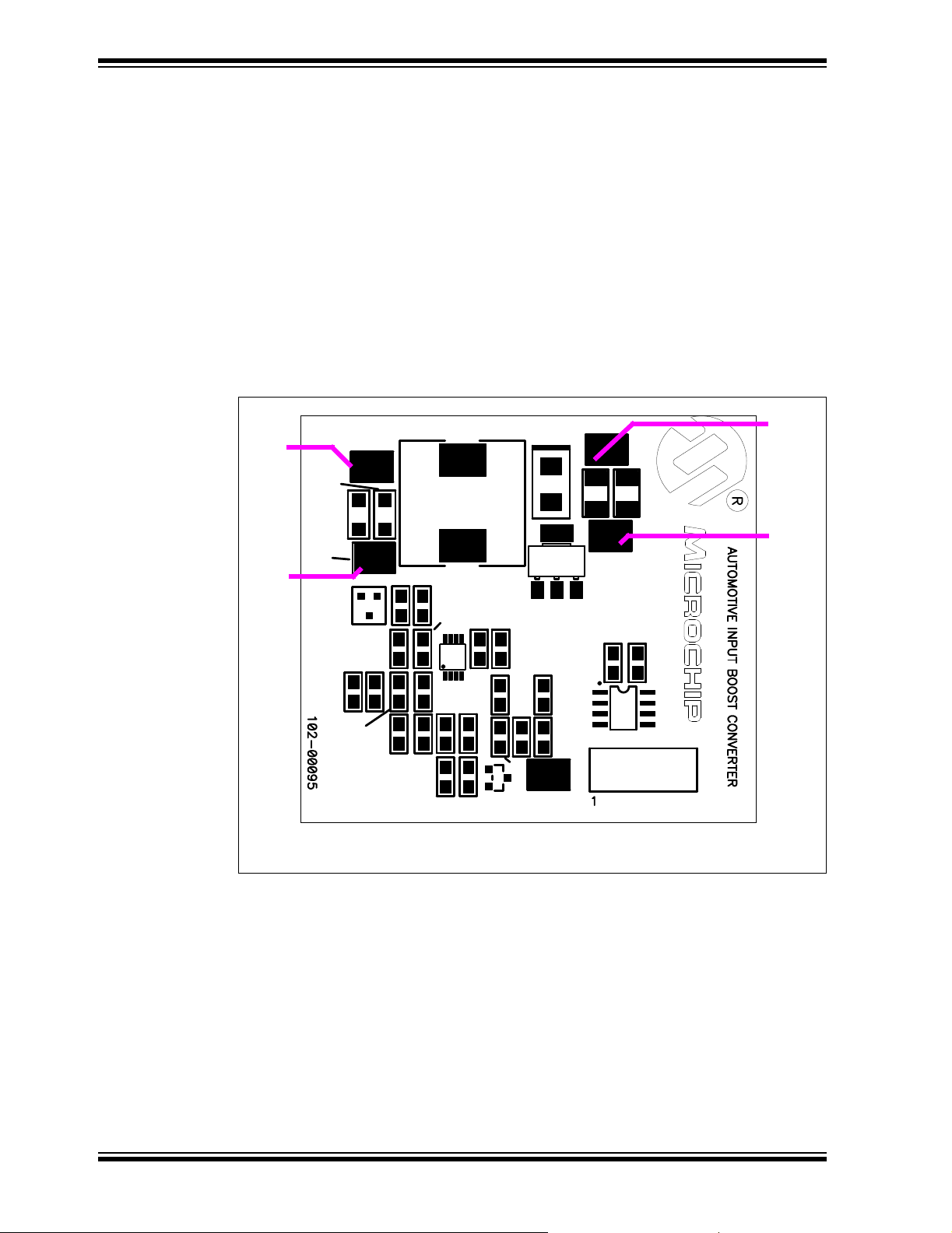
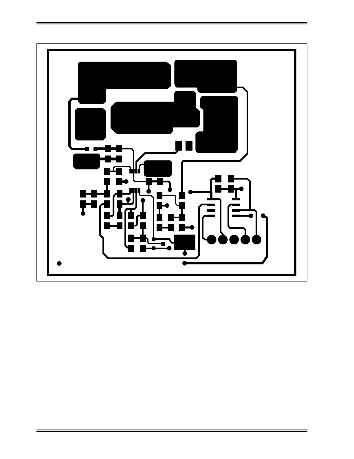
Appendix A. Schematic and Layouts
A.1 INTRODUCTION
This appendix contains the following schematics and layouts for the MCP1630 Automotive Input Boost Converter Demo Board:
• Board – Schematic
• Board – Top Silk Layer
• Board – Top Metal Layer
• Board – Bottom Metal Layer
MCP1630 AUTOMOTIVE INPUT BOOST
CONVERTER DEMO BOARD USER’S GUIDE
© 2007 Microchip Technology Inc. DS51608B-page 11
Page 16

MCP1630 Automotive Input Boost Converter Demo Board User’s Guide
M
3
1
2
A.2 BOARD – SCHEMATIC
DS51608B-page 12 © 2007 Microchip Technology Inc.
Page 17

A.3 BOARD – TOP SILK LAYER
Schematic and Layouts
© 2007 Microchip Technology Inc. DS51608B-page 13
Page 18
MCP1630 Automotive Input Boost Converter Demo Board User’s Guide
A.4 BOARD – TOP METAL LAYER
DS51608B-page 14 © 2007 Microchip Technology Inc.
Page 19

A.5 BOARD – BOTTOM METAL LAYER
Schematic and Layouts
© 2007 Microchip Technology Inc. DS51608B-page 15
Page 20

MCP1630 Automotive Input Boost Converter Demo Board User’s Guide
NOTES:
DS51608B-page 16 © 2007 Microchip Technology Inc.
Page 21

MCP1630 AUTOMOTIVE INPUT BOOST
CONVERTER DEMO BOARD USER’S GUIDE
Appendix B. Bill Of Materials (BOM)
TABLE B-1: BILL OF MATERIALS (BOM)
Qty Reference Description Manufacturer Part Number
2 C1, C2 Cap 4.7uF 25V Ceramic X5R 1206 Panasonic
5 C3, C4, C5,
C10, C11
2 C6, C7 Cap 1uF 16V Ceramic X7R 0805 Panasonic - ECG ECJ-2FB1C105K
1 C8 Cap 1500pF 100V Ceramic X7R 0805 Panasonic - ECG ECJ-2VB2A152K
1 C9 Cap 1000pF 50V Cerm Chip 0805 Panasonic - ECG ECJ-2VC1H102J
2 C12, C13 Cap Cer 4.7uF 50V 10% X7R 1210 Murata GRM32ER71H475KA88L
1 C14 Cap 470pF 50V Cerm Chip 0805 SMD Panasonic - ECG ECJ-2VC1H471J
1 C15 Cap 22pF 50V Cerm Chip 0805 SMD Panasonic - ECG ECJ-2VC1H220J
1 D1 Diode Schottky 60V 1A SMB International Rectifier 10BQ060
1 J1 Conn Header 5 Pos.100 Vert Tin Molex 22-03-2051
1 L1 Inductor Shielded Drum Power 15uH
1 Q1 MOSFET N-CH 55V 3.1A SOT-23 International Rectifier IRLL024N
1 Q2 MOSFET N-CH 60V 280mA SOT-33 Fairchild Semiconductor
1 R1 Res 2.00K Ohm 1/8W 1% 0805 SMD Panasonic - ECG ERJ-6ENF2001V
1 R2 Res 10.0K Ohm 1/8W 1% 0805 SMD Panasonic - ECG ERJ-6ENF10R0V
1 R3 Not Used — —
1 R4 Res 80.6K Ohm 1/8W 1% 0805 SMD Panasonic - ECG ERJ-6ENF8062V
2 R5, R6 Res 100K Ohm 1/8W 1% 0805 SMD Panasonic - ECG ERJ-6ENF1003V
1 R7 Res 49.9K Ohm 1/8W 1% 0805 SMD Panasonic - ECG ERJ-6ENF4992V
1 R8 Res 47.5K Ohm 1/8W 1% 0805 SMD Panasonic - ECG ERJ-6ENF4752V
1 R9 Res 34.0K Ohm 1/8W 1% 0805 SMD Panasonic - ECG ERJ-6ENF3402V
1 R10 Res 2.49K Ohm 1/8W 1% 0805 SMD Panasonic - ECG ERJ-6ENF2491V
1 R11 Res 3.40K Ohm 1/8W 1% 0805 SMD Panasonic - ECG ERJ-6ENF3401V
1 R12 Res 165K Ohm 1/8W 1% 0805 SMD Panasonic - ECG ERJ-6ENF1653V
5 TP1,TP2,
TP3,TP4,
TP5
1 U1 IC 5.0 100 mA LDO Vreg SOT23 National Semiconductor®LM3480IM3-5.0
1 U2 IC MCU Flash 2KX14 8SOIC Microchip Technology Inc PIC12F683-I/SN
1 U3 IC PWM HS MCU-Adaptable 8MSOP Microchip Technology Inc MCP1630V-E/MS
Note 1: The components listed in this Bill of Materials are representative of the PCB assembly. The released BOM
used in manufacturing uses all RoHS-compliant components.
Cap 0.1uF 16V Ceramic X7R 0805 Panasonic - ECG ECJ-2VB1C104K
Coiltronics DR125-150-R
SMD
PC Test point compact SMT Keystone Electronics
®
- ECG ECJ-3YB1E475M
®
NDS7002A
®
5016
© 2007 Microchip Technology Inc. DS51608B-page 17
Page 22

MCP1630 Automotive Input Boost Converter Demo Board User’s Guide
NOTES:
DS51608B-page 18 © 2007 Microchip Technology Inc.
Page 23

Appendix C. Demo Board Firmware
Set PR2 for 500 kHz Freq
Configure Ansel & CMCON0 as Digital I/O
Internal Osc clock to 8 MHz, TMR0 = 0
and GP5 (for Output V
REF
)
Initialize:GP2 (for Output PWM)
Output V
REF
Signal thro’ GP5
Duty Cycle Set by CCPR1L:CCP1CON<5:4>
Start
C.1 DEVICE FIRMWARE
For the latest copy of the MCP1630 Automotive Input Boost Converter Demo Board
User’s Guide firmware, visit our web site at www.microchip.com
MCP1630 AUTOMOTIVE INPUT BOOST
CONVERTER DEMO BOARD USER’S GUIDE
FIGURE C-1: Firmware Flowchart.
© 2007 Microchip Technology Inc. DS51608B-page 19
Page 24

WORLDWIDE SALES AND SERVICE
AMERICAS
Corporate Office
2355 West Chandler Blvd.
Chandler, AZ 85224-6199
Tel: 480-792-7200
Fax: 480-792-7277
Technical Support:
http://support.microchip.com
Web Address:
www.microchip.com
Atlanta
Duluth, GA
Tel: 678-957-9614
Fax: 678-957-1455
Boston
Westborough, MA
Tel: 774-760-0087
Fax: 774-760-0088
Chicago
Itasca, IL
Tel: 630-285-0071
Fax: 630-285-0075
Dallas
Addison, TX
Tel: 972-818-7423
Fax: 972-818-2924
Detroit
Farmington Hills, MI
Tel: 248-538-2250
Fax: 248-538-2260
Kokomo
Kokomo, IN
Tel: 765-864-8360
Fax: 765-864-8387
Los Angeles
Mission Viejo, CA
Tel: 949-462-9523
Fax: 949-462-9608
Santa Clara
Santa Clara, CA
Tel: 408-961-6444
Fax: 408-961-6445
Toronto
Mississauga, Ontario,
Canada
Tel: 905-673-0699
Fax: 905-673-6509
ASIA/PACIFIC
Asia Pacific Office
Suites 3707-14, 37th Floor
Tower 6, The Gateway
Habour City, Kowloon
Hong Kong
Tel: 852-2401-1200
Fax: 852-2401-3431
Australia - Sydney
Tel: 61-2-9868-6733
Fax: 61-2-9868-6755
China - Beijing
Tel: 86-10-8528-2100
Fax: 86-10-8528-2104
China - Chengdu
Tel: 86-28-8665-5511
Fax: 86-28-8665-7889
China - Fuzhou
Tel: 86-591-8750-3506
Fax: 86-591-8750-3521
China - Hong Kong SAR
Tel: 852-2401-1200
Fax: 852-2401-3431
China - Qingdao
Tel: 86-532-8502-7355
Fax: 86-532-8502-7205
China - Shanghai
Tel: 86-21-5407-5533
Fax: 86-21-5407-5066
China - Shenyang
Tel: 86-24-2334-2829
Fax: 86-24-2334-2393
China - Shenzhen
Tel: 86-755-8203-2660
Fax: 86-755-8203-1760
China - Shunde
Tel: 86-757-2839-5507
Fax: 86-757-2839-5571
China - Wuhan
Tel: 86-27-5980-5300
Fax: 86-27-5980-5118
China - Xian
Tel: 86-29-8833-7250
Fax: 86-29-8833-7256
ASIA/PACIFIC
India - Bangalore
Tel: 91-80-4182-8400
Fax: 91-80-4182-8422
India - New Delhi
Tel: 91-11-4160-8631
Fax: 91-11-4160-8632
India - Pune
Tel: 91-20-2566-1512
Fax: 91-20-2566-1513
Japan - Yokohama
Tel: 81-45-471- 6166
Fax: 81-45-471-6122
Korea - Gumi
Tel: 82-54-473-4301
Fax: 82-54-473-4302
Korea - Seoul
Tel: 82-2-554-7200
Fax: 82-2-558-5932 or
82-2-558-5934
Malaysia - Penang
Tel: 60-4-646-8870
Fax: 60-4-646-5086
Philippines - Manila
Tel: 63-2-634-9065
Fax: 63-2-634-9069
Singapore
Tel: 65-6334-8870
Fax: 65-6334-8850
Taiwan - Hsin Chu
Tel: 886-3-572-9526
Fax: 886-3-572-6459
Taiwan - Kaohsiung
Tel: 886-7-536-4818
Fax: 886-7-536-4803
Taiwan - Taipei
Tel: 886-2-2500-6610
Fax: 886-2-2508-0102
Thailand - Bangkok
Tel: 66-2-694-1351
Fax: 66-2-694-1350
EUROPE
Austria - Wels
Tel: 43-7242-2244-39
Fax: 43-7242-2244-393
Denmark - Copenhagen
Tel: 45-4450-2828
Fax: 45-4485-2829
France - Paris
Tel: 33-1-69-53-63-20
Fax: 33-1-69-30-90-79
Germany - Munich
Tel: 49-89-627-144-0
Fax: 49-89-627-144-44
Italy - Milan
Tel: 39-0331-742611
Fax: 39-0331-466781
Netherlands - Drunen
Tel: 31-416-690399
Fax: 31-416-690340
Spain - Madrid
Tel: 34-91-708-08-90
Fax: 34-91-708-08-91
UK - Wokingham
Tel: 44-118-921-5869
Fax: 44-118-921-5820
12/08/06
DS51608B-page 20 © 2007 Microchip Technology Inc.
 Loading...