

Page 1

HV7351
Ultrasound Tx Beamformer
Evaluation Board
User’s Guide
2015 Microchip Technology Inc. DS50002375A
Page 2

Note the following details of the code protection feature on Microchip devices:
YSTEM
CERTIFIE DBYDNV
== ISO/TS16949==
• Microchip products meet the specification contained in their particular Microchip Data Sheet.
• Microchip believes that its family of products is one of the most secure families of its kind on the market today, when used in the
intended manner and under normal conditions.
• There are dishonest and possibly illegal methods used to breach the code protection feature. All of these methods, to our
knowledge, require using the Microchip products in a manner outside the operating specifications contained in Microchip’s Data
Sheets. Most likely, the person doing so is engaged in theft of intellectual property.
• Microchip is willing to work with the customer who is concerned about the integrity of their code.
• Neither Microchip nor any other semiconductor manufacturer can guarantee the security of their code. Code protection does not
mean that we are guaranteeing the product as “unbreakable.”
Code protection is constantly evolving. We at Microchip are committed to continuously improving the code protection features of our
products. Attempts to break Microchip’s code protection feature may be a violation of the Digital Millennium Copyright Act. If such acts
allow unauthorized access to your software or other copyrighted work, you may have a right to sue for relief under that Act.
Information contained in this publication regarding device
applications and the like is provided only for your convenience
and may be superseded by updates. It is your responsibility to
ensure that your application meets with your specifications.
MICROCHIP MAKES NO REPRESENTATIONS OR
WARRANTIES OF ANY KIND WHETHER EXPRESS OR
IMPLIED, WRITTEN OR ORAL, STATUTORY OR
OTHERWISE, RELATED TO THE INFORMATION,
INCLUDING BUT NOT LIMITED TO ITS CONDITION,
QUALITY, PERFORMANCE, MERCHANTABILITY OR
FITNESS FOR PURPOSE. Microchip disclaims all liability
arising from this information and its use. Use of Microchip
devices in life support and/or safety applications is entirely at
the buyer’s risk, and the buyer agrees to defend, indemnify and
hold harmless Microchip from any and all damages, claims,
suits, or expenses resulting from such use. No licenses are
conveyed, implicitly or otherwise, under any Microchip
intellectual property rights.
Trademarks
The Microchip name and logo, the Microchip logo, dsPIC,
FlashFlex, flexPWR, JukeBlox, K
LANCheck, MediaLB, MOST, MOST logo, MPLAB,
OptoLyzer, PIC, PICSTART, PIC
SST, SST Logo, SuperFlash and UNI/O are registered
trademarks of Microchip Technology Incorporated in the
U.S.A. and other countries.
The Embedded Control Solutions Company and mTouch are
registered trademarks of Microchip Technology Incorporated
in the U.S.A.
Analog-for-the-Digital Age, BodyCom, chipKIT, chipKIT logo,
CodeGuard, dsPICDEM, dsPICDEM.net, ECAN, In-Circuit
Serial Programming, ICSP, Inter-Chip Connectivity, KleerNet,
KleerNet logo, MiWi, MPASM, MPF, MPLAB Certified logo,
MPLIB, MPLINK, MultiTRAK, NetDetach, Omniscient Code
Generation, PICDEM, PICDEM.net, PICkit, PICtail,
RightTouch logo, REAL ICE, SQI, Serial Quad I/O, Total
Endurance, TSHARC, USBCheck, VariSense, ViewSpan,
WiperLock, Wireless DNA, and ZENA are trademarks of
Microchip Technology Incorporated in the U.S.A. and other
countries.
SQTP is a service mark of Microchip Technology Incorporated
in the U.S.A.
Silicon Storage Technology is a registered trademark of
Microchip Technology Inc. in other countries.
GestIC is a registered trademarks of Microchip Technology
Germany II GmbH & Co. KG, a subsidiary of Microchip
Technology Inc., in other countries.
All other trademarks mentioned herein are property of their
respective companies.
© 2015, Microchip Technology Incorporated, Printed in the
U.S.A., All Rights Reserved.
ISBN: 978-1-63277-403-3
EELOQ, KEELOQ logo, Kleer,
32
logo, RightTouch, SpyNIC,
QUALITYMANAGEMENTS
DS50002375A-page 2 2015 Microchip Technology Inc.
Microchip received ISO/TS-16949:2009 certification for its worldwide
headquarters, design and wafer fabrication facilities in Chandler and
Tempe, Arizona; Gresham, Oregon and design centers in California
and India. The Company’s quality system processes and procedures
are for its PIC
devices, Serial EEPROMs, microperipherals, nonvolatile memory and
analog products. In addition, Microchip’s quality system for the design
and manufacture of development systems is ISO 9001:2000 certified.
®
MCUs and dsPIC® DSCs, KEELOQ
®
code hopping
Page 3
Object of Declaration: HV7351 Ultrasound Tx Beamformer Evaluation Board
2015 Microchip Technology Inc. DS50002375A-page 3
Page 4

NOTES:
DS50002375A-page 4 2015 Microchip Technology Inc.
Page 5

HV7351
ULTRASOUND TX BEAMFORMER
EVALUATION BOARD USER’S GUIDE
Table of Contents
Preface ........................................................................................................................... 7
Introduction............................................................................................................ 7
Document Layout .................................................................................................. 7
Conventions Used in this Guide ........................................................................... 8
Recommended Reading........................................................................................ 9
The Microchip Web Site ........................................................................................ 9
Customer Support ................................................................................................. 9
Document Revision History ................................................................................... 9
Chapter 1. Product Overview
1.1 Introduction ................................................................................................... 11
1.2 HV7351 Device Overview ............................................................................ 11
1.3 Board Overview ............................................................................................ 11
1.4 What the HV7351 Ultrasound Tx Beamformer Evaluation Board
Kit Includes ............................................................................................. 13
Chapter 2. Installation and Operation
2.1 Getting Started ............................................................................................. 15
2.2 Setup Procedure .......................................................................................... 15
2.3 Evaluating The HV7351 Ultrasound Tx Beamformer Evaluation Board ....... 18
2.4 Normal Operation ......................................................................................... 18
Chapter 3. Printed Circuit Board Layout Techniques
Appendix A. Schematic and Layouts
A.1 Introduction .................................................................................................. 21
A.2 Board – Schematic ....................................................................................... 22
A.3 Board – Top Layer ....................................................................................... 23
A.4 Board – Top Silk Layer ................................................................................ 23
A.5 Board – Middle Layer ................................................................................... 24
A.6 Board – Bottom Layer .................................................................................. 24
A.7 Board – Bottom Silk Layer ........................................................................... 25
A.8 Board – All Layers, and Dimension .............................................................. 25
Appendix B. Bill of Materials (BOM)........................................................................... 27
Appendix C. Plots and Waveforms
C.1 HV7351 Typical Waveforms ........................................................................ 29
Worldwide Sales and Service .................................................................................... 34
2015 Microchip Technology Inc. DS50002375A-page 5
Page 6

HV7351 Ultrasound Tx Beamformer Evaluation Board User’s Guide
NOTES:
DS50002375A-page 6 2015 Microchip Technology Inc.
Page 7

HV7351
ULTRASOUND TX BEAMFORMER
EVALUATION BOARD USER’S GUIDE
Preface
NOTICE TO CUSTOMERS
All documentation becomes dated, and this manual is no exception. Microchip tools and
documentation are constantly evolving to meet customer needs, so some actual dialogs
and/or tool descriptions may differ from those in this document. Please refer to our web site
(www.microchip.com) to obtain the latest documentation available.
Documents are identified with a “DS” number. This number is located on the bottom of each
page, in front of the page number. The numbering convention for the DS number is
“DSXXXXXXXXA”, where “XXXXXXXX” is the document number and “A” is the revision level
of the document.
For the most up-to-date information on development tools, see the MPLAB
Select the Help menu, and then Topics to open a list of available online help files.
®
IDE online help.
INTRODUCTION
This chapter contains general information that will be useful to know before using the
HV7351 Ultrasound Tx Beamformer Evaluation Board. Items discussed in this chapter
include:
• Document Layout
• Conventions Used in this Guide
• Recommended Reading
• The Microchip Web Site
• Customer Support
• Document Revision History
DOCUMENT LAYOUT
This document describes how to use the HV7351 Ultrasound Tx Beamformer
Evaluation Board as a development tool to emulate and debug firmware on a target
board. The manual layout is as follows:
• Chapter 1. “Product Overview” – Important information about the HV7351
Ultrasound Tx Beamformer Evaluation Board.
• Chapter 2. “Installation and Operation” – This chapter includes a detailed
description of each function of the demonstration board and instructions on how to
begin using the board.
• Chapter 3. “Printed Circuit Board Layout Techniques” – This chapter provides
in-depth information on the recommended PCB Layout Techniques to optimally
use the board.
• Appendix A. “Schematic and Layouts” – Shows the schematic and layout
diagrams for the HV7351 Ultrasound Tx Beamformer Evaluation Board.
• Appendix B. “Bill of Materials (BOM)” – Lists the parts used to build the
HV7351 Ultrasound Tx Beamformer Evaluation Board.
• Appendix C. “Plots and Waveforms” – Describes the various plots and
waveforms for the HV7351 Ultrasound Tx Beamformer Evaluation Board.
2015 Microchip Technology Inc. DS50002375A-page 7
Page 8
HV7351 Ultrasound Tx Beamformer Evaluation Board User’s Guide
CONVENTIONS USED IN THIS GUIDE
This manual uses the following documentation conventions:
DOCUMENTATION CONVENTIONS
Description Represents Examples
Arial font:
Italic characters Referenced books MPLAB® IDE User’s Guide
Emphasized text ...is the only compiler...
Initial caps A window the Output window
A dialog the Settings dialog
A menu selection select Enable Programmer
Quotes A field name in a window or
dialog
Underlined, italic text with
right angle bracket
Bold characters A dialog button Click OK
N‘Rnnnn A number in verilog format,
Text in angle brackets < > A key on the keyboard Press <Enter>, <F1>
Courier New font:
Plain Courier New Sample source code #define START
Italic Courier New A variable argument file.o, where file can be
Square brackets [ ] Optional arguments mcc18 [options] file
Curly brackets and pipe
character: { | }
Ellipses... Replaces repeated text var_name [,
A menu path File>Save
A tab Click the Power tab
where N is the total number of
digits, R is the radix and n is a
digit.
Filenames autoexec.bat
File paths c:\mcc18\h
Keywords _asm, _endasm, static
Command-line options -Opa+, -Opa-
Bit values 0, 1
Constants 0xFF, ‘A’
Choice of mutually exclusive
arguments; an OR selection
Represents code supplied by
user
“Save project before build”
4‘b0010, 2‘hF1
any valid filename
[options]
errorlevel {0|1}
var_name...]
void main (void)
{ ...
}
DS50002375A-page 8 2015 Microchip Technology Inc.
Page 9

RECOMMENDED READING
This user’s guide describes how to utilize the HV7351 Ultrasound Tx Beamformer
Evaluation Board. Another useful document is listed below. The following Microchip
document is available and recommended as a supplemental reference resource.
• HV7351 Data Sheet – “8-Channel ±70V 3A Programmable High Voltage
Ultrasound Transmit Beamformer” (DS20005412).
THE MICROCHIP WEB SITE
Microchip provides online support via our web site at www.microchip.com. This web
site is used as a means to make files and information easily available to customers.
Accessible by using your favorite Internet browser, the web site contains the following
information:
• Product Support – Data sheets and errata, application notes and sample
programs, design resources, user’s guides and hardware support documents,
latest software releases and archived software
• General Technical Support – Frequently Asked Questions (FAQs), technical
support requests, online discussion groups, Microchip consultant program
member listing
• Business of Microchip – Product selector and ordering guides, latest Microchip
press releases, listing of seminars and events, listings of Microchip sales offices,
distributors and factory representatives
Preface
CUSTOMER SUPPORT
Users of Microchip products can receive assistance through several channels:
• Distributor or Representative
• Local Sales Office
• Field Application Engineer (FAE)
• Technical Support
Customers should contact their distributor, representative or field application engineer
(FAE) for support. Local sales offices are also available to help customers. A listing of
sales offices and locations is included in the back of this document.
Technical support is available through the web site at:
http://www.microchip.com/support
DOCUMENT REVISION HISTORY
Revision A (June 2015)
• Initial Release of this Document.
2015 Microchip Technology Inc. DS50002375A-page 9
Page 10

HV7351 Ultrasound Tx Beamformer Evaluation Board User’s Guide
NOTES:
DS50002375A-page 10 2015 Microchip Technology Inc.
Page 11

Chapter 1. Product Overview
1.1 INTRODUCTION
This chapter discusses the following topics:
• HV7351 Device Overview
• Board Overview
• What the HV7351 Ultrasound Tx Beamformer Evaluation Board Kit Includes
1.2 HV7351 DEVICE OVERVIEW
The Microchip Technology Inc. HV7351 is a monolithic, eight channel, high-speed,
high-voltage ultrasound transmitter Return-To-Zero (RTZ) programmable pulser. This
integrated, high-performance circuit comes in a single 11 x 11 x 0.9 mm, 80-lead DFN
package.
Each channel is capable of swinging up to ±70V with an active discharge back to 0V.
The outputs can source and sink more than 3A to achieve fast output rise and fall times.
The active discharge is also capable of sourcing and sinking 3A for a fast return to
ground. The digital beamforming topology of the HV7351 will significantly reduce the
number of I/O logic control lines to the transmitter.
Each output is controlled by a 16 or 32-bit serial shift register. An arbitrary pattern can
be generated depending on what is loaded into the shift registers, including four
independent pattern options.
Once the patterns are loaded, the user can quickly select any of the four predefined
patterns without having to clock in new data. A programmable 10-bit delay counter is
provided for each output. This allows the user to program different delay times for each
channel for beamforming.
HV7351
ULTRASOUND TX BEAMFORMER
EVALUATION BOARD USER’S GUIDE
1.3 BOARD OVERVIEW
There are two built-in Complex Programmable Logic Devices (CPLDs) and one serial
EEPROM on the board to provide multiple demo waveform patterns. Other custom
experimental data can be easily downloaded to these CPLDs/PROMs via the 6-pin
Joint Test Action Group (JTAG) interface.
The HV7351 Board output waveforms can be directly displayed using an oscilloscope,
by connecting the scope probe to the test points TX1 - TX8 and GND. The soldering
jumper can select whether or not to connect the on-board dummy-load, a 330 pF
capacitor paralleling with a 2.5 k resistor. The test points can be used to connect the
user’s transducer to easily evaluate the pulser.
2015 Microchip Technology Inc. DS50002375A-page 11
Page 12

HV7351 Ultrasound Tx Beamformer Evaluation Board User’s Guide
VLL
DGND
V
PP
+3.3V
VPP
VDD
TX1
R8
Waveform
Generator
CPLD
+3.3V
OSC
JTAG
EXCLK
EN
CLK
IN
WAVE
FREQ
INVERT
ENA
CW
160 MHz
6
LRP
PGND
TP11
X1
330 pF
330 pF
PGND
R53
TP37
X8
TX8
HV
OUT
EXTRG
IN-System
PROM
VRP
+5.0V +5.0 to 12V
+3.0 to 70V
VPF
SPI &
Control
Logic
CW
INV
PWR
EN
V
RN
CW, SIZE, A [1:0]
SP1
TRIG
EN
TCK
AGND
Pattern
Registers
Delay
Registers
PreScale
Registers
VNN
-3.0 to -70V
VNF
LRN
V
RP
VRNVSS
-5.0V
PGND
SUB
V
PP
P
GND
P
GND
V
NN
P
GND
-5.0 to -12V
HV7351
1 of 8
Channels Shown
V
PF
V
NF
V
NN
GND
V
RN
V
RP
GND
Dummy
Load
2.5 k
Dummy
Load
2.5 k
VCC
FIGURE 1-1: Block Diagram.
1.3.1 Board Features
• Two CPLDs provided to program a wide variety of data patterns that can be
transmitted.
• Push-button selection of various Waveforms, Transmission Frequency, Waveform
Inversion, Mode (Brightness or Continuous Wave mode) and Enable (see
Ta bl e 2 - 3 in Chapter 2. “Installation and Operation”)
• LED indication of push button operations (see Tab le 2 - 4 in Chapter
2. “Installation and Operation”)
• Ability to bypass the crystal oscillator provided with an external clock source
• Numerous test points for probing of various input and output signals
1.3.2 HV7351 Ultrasound Tx Beamformer Evaluation Board Hardware
Components
The HV7351 Ultrasound Tx Beamformer Evaluation Board contains several
components:
• One HV7351 8-Channel ±70V, 3A Programmable Ultrasound Transmit
Beamformer.
• Two Xilinx Inc. XC9572XL_VQ44 CPLDs
• Two Xilinx Inc. XCF01SVO20C PROM
• One Fox
DS50002375A-page 12 2015 Microchip Technology Inc.
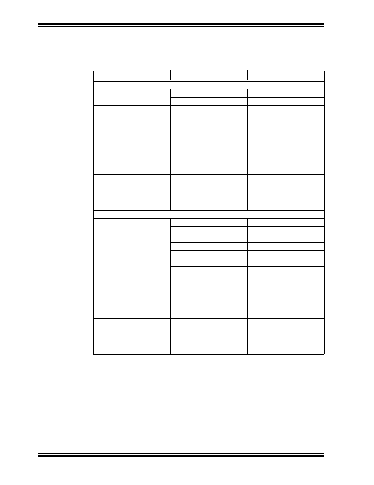
TABLE 1-1: TECHNICAL SPECIFICATIONS
Modes of Operation B-mode and CW-mode
Input Logic Level 3.3V
Transmission Frequency 1 MHz – 10 MHz
High Voltage Supply Range ±3V – ±70V
Load on Each Channel 330 pF||2.5 k
Electronics FXO-HC73-160 crystal oscillator running at 160 MHz
Parameter Value
Page 13

1.4 WHAT THE HV7351 ULTRASOUND TX BEAMFORMER EVALUATION BOARD KIT INCLUDES
The HV7351 Ultrasound Tx Beamformer Evaluation Board Kit includes:
• HV7351 Ultrasound Tx Beamformer Evaluation Board (ADM00658)
• Important Information Sheet
FIGURE 1-2: HV7351 Ultrasound Tx Beamformer Evaluation Board Front View.
FIGURE 1-3: HV7351 Ultrasound Tx Beamformer Evaluation Board Back View.
2015 Microchip Technology Inc. DS50002375A-page 13
Page 14

HV7351 Ultrasound Tx Beamformer Evaluation Board User’s Guide
NOTES:
DS50002375A-page 14 2015 Microchip Technology Inc.
Page 15

EVALUATION BOARD USER’S GUIDE
Chapter 2. Installation and Operation
2.1 GETTING STARTED
The HV7351 Ultrasound Tx Beamformer Evaluation Board is fully assembled and
tested. The board requires external voltage sources.
2.1.1 Additional Tools Required for Operation
• A DC power supply, a bench supply that can produce 3.3V, 5V, -5V, 12V, -12V,
70V and -70V
• An oscilloscope and/or a multi-meter to observe the waveforms and measure
electrical parameters
2.2 SETUP PROCEDURE
To operate the HV7351 Ultrasound Tx Beamformer Evaluation Board, the following
steps must be followed:
HV7351
ULTRASOUND TX BEAMFORMER
WARNING
Read the HV7351 Ultrasound Tx Beamformer Evaluation Board User’s Guide (this
document) fully before proceeding to board setup.
1. Connect the supplies correctly to the board as shown in Figure 2-1.
2. Set the voltages and current limits of the supply rails according to Ta bl e 2 - 1,
before connecting the power connector J4.
TABLE 2-1: POWER CONNECTOR DESCRIPTION
Pin Name Description
1 VCC +3.3V Logic voltage input for V
2 GND 0V, Ground
3 VDD +5.0V HV7351 Board positive V
4 VSS -5.0V HV7351 Board negative V
5 VRN -5.0V to -12V HV7351 Board negative regulator supply, 50 mA
6 VRP +5.0V to +12V HV7351 Board positive regulator supply, 50 mA
7 GND 0V, Ground
8 VNN -3.0V to -70V negative high-voltage supply, 10 mA to 50 mA (Note 1)
9 GND 0V, Ground
10 VPP +3.0V to +70V positive high-voltage supply, 10 mA to 50 mA (Note 1)
Note 1: The current limits given for V
program in which B/CW-mode transmission is limited to about 16 cycles.
If the user reprograms the CPLD for more CW cycles, the current limits
need to be similarly increased.
and CPLD, 200 mA
LL
supply, 50 mA
DD
supply, 50 mA
SS
and VNN are good for the supplied CPLD
PP
2015 Microchip Technology Inc. DS50002375A-page 15
Page 16

DS50002375A-page 16 2015 Microchip Technology Inc.
VLL
DGND
V
PP
+3.3V
VPP
VDD
TX1
R8
Waveform
Generator
CPLD
+3.3V
OSC
JTAG
EXCLK
EN
CLK
IN
WAVE
FREQ
INVERT
ENA
CW
160 MHz
6
LRP
PGND
TP11
X1
330 pF
330 pF
PGND
R53
TP37
X8
TX8
HV
OUT
EXTRG
IN-System
PROM
VRP
+5.0V +5.0 to 12V
+3.0 to 70V
VPF
SPI &
Control
Logic
CW
INV
PWR
EN
V
RN
CW, SIZE, A [1:0]
SP1
TRIG
EN
TCK
AGND
Pattern
Registers
Delay
Registers
PreScale
Registers
VNN
-3.0 to -70V
VNF
LRN
V
RP
VRNVSS
-5.0V
PGND
SUB
V
PP
P
GND
P
GND
V
NN
P
GND
-5.0 to -12V
HV7351
1 of 8
Channels Shown
V
PF
V
NF
V
NN
GND
V
RN
V
RP
GND
Dummy
Load
2.5 k
Dummy
Load
2.5 k
VCC
HV7351 Ultrasound Tx Beamformer Evaluation Board User’s Guide
FIGURE 2-1: Power Supply and Load Connection Diagram.
Page 17

3. Connect the high-impedance probe(s) of the oscilloscope to the Tx output(s).
4. Power up the supplies according to the power-up sequence as indicated in
Ta bl e 2 - 2.
TABLE 2-2: SUPPLY POWER-UP SEQUENCE
Step Name Description
1 +VCC +3.3V positive logic supply voltage for HV7351 Board V
CPLD V
CC
LL
and
2 +VDD +5.0V positive power supply
3 -VSS -5.0V negative power supply
4 +VRP +5V to +12.0V positive CW power supply
5 -VRN -5V to -12.0V positive CW power supply
6 +VPP +3V to +70V positive high voltage supply
7 -VNN -3V to -70V positive high voltage supply
5. After the HV7351 Board has been successfully powered up by following the
power-up sequence, enable the board by pressing the ENA button.
6. Change the output waveform and transmit frequency by pressing the WAVE and
FREQ buttons, respectively. An overview of Push Button Operations is provided
in Ta bl e 2 - 3.
TABLE 2-3: PUSH BUTTON OPERATIONS
Button Description
WAVE Toggle select pulse waveforms
FREQ Toggle select B-mode demo frequency
INVERT Toggle select non-inverting or inverting waveform
CW Toggle select CW-mode or B-mode (Note 1)
ENA Toggle ON or OFF HV7351 Board enable signal EN
Note 1: In CW-mode, V
PP/VNN
voltages must be reduced to ±8V
7. The output waveform can be inverted by pressing the INVERT button. Tab le 2 -4
lists all LED Indicators.
TABLE 2-4: LED INDICATORS
LED Description
CW CW-mode indicator
INVERT Inverting waveform output indicator
PWR V
3.3V and CPLD chip VCC power supply ON indicator
LL
ENA IC-enabled indicator. CPDL power-up default is OFF
8. The transmission mode can be toggled by pressing the CW button. In CW-mode,
the typical waveforms are 16-cycle 5 MHz. To prevent the HV7351 Board from
overheating, the following parameters are recommended when setting V
PP/VNN
voltages in CW-mode:
•+3VV
•-3V V
2015 Microchip Technology Inc. DS50002375A-page 17
PP
NN
-8V
+8V
Page 18

HV7351 Ultrasound Tx Beamformer Evaluation Board User’s Guide
WARNING
Carefully double-check the voltage of every supply rail, current-limit value and
polarity individually to avoid board damage.
Take extreme care while connecting the supplies to the board since
connecting them incorrectly to the wrong pins could result in permanent
damage to the entire board.
2.3 EVALUATING THE HV7351 ULTRASOUND TX BEAMFORMER EVALUATION BOARD
The best way to evaluate the HV7351 Ultrasound Tx Beamformer Evaluation Board is
to explore the circuit and measure the voltages and currents with a Digital Voltage
Meter (DVM) while probing the board with an oscilloscope.
2.4 NORMAL OPERATION
The HV7351 Ultrasound Tx Beamformer Evaluation Board should be powered up with
multiple lab DC power supplies that feature current-limiting functions.
To meet the typical loading condition when using the high-impedance probe of an
oscilloscope, the on-board dummy load (330 pF||2.5 k) should be connected to the
high-voltage pulser output through the solder jumper. To evaluate different loading
conditions, the values of the RC may be changed within the current and power limits of
the device.
In order to drive the user’s piezoelectric transducers with a cable, the output load
impedance should be properly matched to avoid cable and transducer reflections.
A 70 to 75 k coaxial cable is recommended. The coaxial cable end should be
soldered to the TX1 - TX8 and GND directly with very short leads. If the user’s load is
being used, the on-board dummy load should be disconnected by cutting the small
shorting copper trace in between the 0k resistors (R8, R12, R29, R30, R10, R37, R52
and R53) and the eight resistor pads. They are shorted by factory default.
All on-board test points are designed to work with the high-impedance probe of an
oscilloscope. Some probes may have limited input voltage range. When using the
probe on these high-voltage test points, make sure that the V
exceed the probe limit. When using the high-impedance oscilloscope probe on the
on-board test points, it is important to have short ground leads to the circuit board
ground plane.
PP/VNN
voltages do not
DS50002375A-page 18 2015 Microchip Technology Inc.
Page 19

HV7351
ULTRASOUND TX BEAMFORMER
EVALUATION BOARD USER’S GUIDE
Chapter 3. Printed Circuit Board Layout Techniques
The large thermal pad at the bottom of the HV7351 package is internally connected to
the IC’s substrate (V
externally on the PCB. The designer needs to pay attention to the connecting traces on
the outputs TX1 - TX8, specifically the high-voltage and high-speed traces. In
particular, controlled impedance to ground plane and more trace spacing needs to be
applied in such situations.
High-speed PCB trace design practices that are compatible with about
50 MHz to 100 MHz operating speeds are used for the HV7351 PCB layout. The
internal circuitry of the HV7351 can operate at rather high frequencies, the primary
speed limitation being the load capacitance.
Because of the high-speed and high-transient currents that result when driving
capacitive loads, the supply-voltage bypass capacitors should be as close to the pins
as possible. The GND pin should have low inductance feed-through via connections
that are soldered directly to a solid ground plane.
The device’s V
supplies and bypass capacitors pins must have a ceramic capacitor per pin and be
placed close to the pin. A ceramic capacitor of 1.0 µF may be used. Only the V
V
to GND capacitors need to be high-voltage type. The VPF to VPP and VNF to VNN
NN
capacitors can be low-voltage.
It is advisable to minimize the trace length to the ground plane and to insert a ferrite
bead in the power supply lead to the capacitor to prevent resonance within the power
supply lines. For applications that are sensitive to jitter and noise, and when using
multiple HV7351 ICs, another ferrite bead between each of the chip’s supply line should
be inserted.
To reduce inductance, special attention should be paid to minimizing trace lengths and
using sufficient trace width. Surface mount components are highly recommended.
Since the output impedance of the HV7351 high-voltage power stages is very low, in
some cases it may be desirable to add a small value resistor in series with the output
TX1 - TX8. This results in obtaining better waveform integrity at the load terminals after
long cables and will also reduce the output voltage slew rate at the terminals of a
capacitive load.
Special attention should be paid to the parasitic coupling from the outputs to the input
signal terminals of the HV7351. This feedback may cause oscillations or spurious
waveform shapes on the edges of signal transitions. Since the input operates with
signals down to 3.3V, even small coupling voltages may cause problems. The use of a
solid ground plane and good power and signal layout practices will prevent this
problem.
It should also be ensured that the circulating ground return current from the capacitive
load cannot react with common inductance to create noise voltages in the input
circuitry.
, AVDD, DVDD, PVDD, PVSS, VPP, VNN, VPF, VNF and VRN voltage
LL
). This thermal pad should be connected to 0V or GND
SUB
PP
and
2015 Microchip Technology Inc. DS50002375A-page 19
Page 20

HV7351 Ultrasound Tx Beamformer Evaluation Board User’s Guide
NOTES:
DS50002375A-page 20 2015 Microchip Technology Inc.
Page 21

Appendix A. Schematic and Layouts
A.1 INTRODUCTION
This appendix contains the following schematics and layouts for the HV7351
Ultrasound Tx Beamformer Evaluation Board:
• Board – Schematic
• Board – Top Layer
• Board – Top Silk Layer
• Board – Middle Layer
• Board – Bottom Layer
• Board – Bottom Silk Layer
• Board – All Layers, and Dimension
HV7351
ULTRASOUND TX BEAMFORMER
EVALUATION BOARD USER’S GUIDE
2015 Microchip Technology Inc. DS50002375A-page 21
Page 22

36
40
32
29
28
33
8
38
42
1
41
34
B0
B1
B2
B3
B4
B5
B6
B7
B8
B9
B10
B11
TDO
TCK
TDI
TMS
TX1
OERST
EN
SDI
SDO
SCK
CS
TRIG
LED1 LED2 PWR
LED1
LED2
PWR
EN
CLKOUT
CLKOUT
D0
FCLK
CF
CE
CEO
D0
FCLK
CF
OERST
CE
CEO
VCC
VCC
VCC
VCC
VCC
VCC
VDD
VPP
VNN
VSS
VRP
VRN
VCC
J6
JTAG
V
CC
= +3.3V
V
DD/VSS
= +/-5V
V
RP/VRN
= +/-5V to +/-10V
V
PP/VNN
= +/-5 to +/-70V
R1
1k
R41
4.99k
NC9
NC8
NC7
374439433130273526
15
CC
DD
EE
FF
GG
HH
II
JJ
KK
LL
MM
NN
36
40
32
29
28
33
8
38
42
1
41
34
U3
XC9572XL_VQ44
TP44
TP45
TP43
C12
0.1
D4
YLW
TP36
C29
0.1
TP5
R42
4.99k
TP2
TP48
R14
1k
1
2
3
J1
EXCLK
C43
1μF
TP46
18
19
AVDD
DVDD
DVDD
PVDD
PVDD
PVDD
PVDD
VRP
1501079225249
9
16
3
6
20
2
17
7
8
GND
DGND
DGND
DGND
DGND
8111514358
5
13
PGND
PGND
PGND
PGND
PGND
PGND
PGND
PGND
23
78
53
48
46
77
55
24
PVSS
PVSS
PVSS
PVSS
254754
76
SIZE
INV
CW
A0
A1
EN
DIN1
DOUT1
DIN2
DOUT2
SCK
CS1
CS2
TRIG
TCK
TCK
NC
NC
4
12
TX1
TX2
TX3
TX4
TX5
TX6
TX7
TX8
30
33
36
39
62
65
68
71
VLL
15
VNF
VNF
VNF
VNF
VNN
VNN
VNN
VNN
VNN
VNN
VNN
VNN
VNN
VNN
614035346766296041
72
VPF
VPF
VPF
VPF
VPP
VPP
VPP
VPP
VPP
VPP
VPP
VPP
VPP
VPP
14
VRN
21
80
U1
HV7351
WAV
FRE
INVERTCWENA
23567
GND
4
TDI1
9
TMS
10
TCK
11
GND
17
TDO1
24
GND
25
NC11 30
NC12
31
VCC
VCC
VCC
352615
EXTRG
39
CLKIN
43
NC10 27
CLKOUT
44
SIZE
INV
CW
A0
A1
EN
U2
XC9572XL_VQ44
12345
6
R6
1k
TP42
C40
0.1
TP27
TP25
EN
1
GND2OUT
3
VCC
4
X1
FXO-HC73-160
1
2
J2
EX = 0
TP3
TP16
TP30
D0
CLK
CF
OE_RST
CE
CEO
1
3
7
8
10
13
NC
NC
NC
NC
NC
NC
2
9
12
15
14
16
TMS
TDI3
TDO3
TCK
5417
6
GND
11
VCCJ
VCCO
VVVINT
201918
U4
XCF01SVO20C
TP41
TP47
1
2
3
MH4MH3MH2 MH1
R43
4.99k
C41
0.1
VCC VRPVSS VNNVRN VPPVDD
123456789
10
J4
HEADER 10
R36
10
R33
10
R38
1
R35
1
R39
1
R40
1
R31
1
VCC
VNNVDD VPPVRP VRN VDD
VSS
VCC
VSS
VNN
D17
6
1
D15
B1100-13
D21B
BAT54DW-7
6
1
6
1
4
3
4
3
4
3
1
2
211
2
D16
B1100-13
D17
B1100-13
D21A
BAT54DW-7
D20B
BAT54DW-7
D20A
BAT54DW-7
D19B
BAT54DW-7
D19A
BAT54DW-7
TP28
R9
2.55k
1W
R8
C4
330p
250V
TP17
TP11
R13
2.55k
1W
R12
C25
330p
250V
TP22
TP19
R27
2.55k
1W
R29
C22
330p
250V
TP31
TP23
R28
2.55k
1W
R30
C32
330p
250V
TP34
TP32
R11
2.55k
1W
R10
C13
330p
250V
TP21
TP13
R54
2.55k
1W
R37
C24
330p
250V
TP39
TP26
R32
2.55k
1W
R52
C23
330p
250V
TP33
TP24
R34
2.55k
1W
R53
C39
330p
250V
TP38
TP37
TX2
TX3
TX4
TX5
TX6
TX7
TX8
C44
1μF
C36
1μF
C42
1μF
C55
1μF
27
74
C27
1μF
100V
C46
1μF
100V
C33
1μF
100V
C47
1μF
100V
C45
1μF
C34
1μF
C28
1μF
C26
1μF
TP40
594273
28
22
16
23
14
13
Z
Y
X
V
U
C20
0.1
R15
1k
TP1
C21
0.1
C53
1μF
C14
1μF
C17
1μF
C19
1μF
C52
1μF
TP29
C54
1μF
C50
1μF
C51
1μF
C15
1μFC51μF
C9
0.1
C10
0.1
C11
0.1
C16
1μF
100V
C18
1μF
100V
C48
1μF
100V
C56
1μF
100V
C49
1μF
100V
383731706963326444
57
755626
45
TP35
R5
1kR41kR31k
D1
YLWD2RED
D3
GRN
1
2
1
2
1
2
1
2
C1
0.1
J3
EXTRG
18
20
19
21
12
22
16
23
14
13
OERST
EN
SDI
SDO
SCK
CS
TRIG
B0
B1
B2
B3
B4
B5
B6
B7
B8
B9
B10
B11
C
D
E
F
G
H
I
J
K
L
M
N
EN
SDI
SDO
SCK
CS
TRIG
TP18
TP14
TP10
TP15
TP8
TP9
TP7
TP12
TP6
TP4
4
17
25
23567109
24
11
GND
GND
GNDD0FCLKCFCE
CEO
TMS
TDI2
TDO2
TCK
C6
0.1C70.1C80.1
R2
50
R7
50
BB
AA
EXTRG
CLKIN
LED1
LED2
PWR
VCC
VCC
VCC
VCC
TP20
R26
200
C30
0.1
R25
200
R24
200
R23
200
R22
200
C31
0.1
C37
0.1
C38
0.1
C35
0.1
SW1
R17
33k
SW5
R21
33k
SW2
R18
33k
SW4
R20
33k
SW3
R19
33k
37
18
20
19
21
12
2015 Microchip Technology Inc. DS50002375A-page 22
A.2 BOARD – SCHEMATIC
Page 23

A.3 BOARD – TOP LAYER
A.4 BOARD – TOP SILK LAYER
2015 Microchip Technology Inc. DS50002375A-page 23
Page 24

HV7351 Ultrasound Tx Beamformer Evaluation Board User’s Guide
A.5 BOARD – MIDDLE LAYER
A.6 BOARD – BOTTOM LAYER
DS50002375A-page 24 2015 Microchip Technology Inc.
Page 25

A.7 BOARD – BOTTOM SILK LAYER
A.8 BOARD – ALL LAYERS, AND DIMENSION
2015 Microchip Technology Inc. DS50002375A-page 25
Page 26

HV7351 Ultrasound Tx Beamformer Evaluation Board User’s Guide
NOTES:
DS50002375A-page 26 2015 Microchip Technology Inc.
Page 27

HV7351
ULTRASOUND TX BEAMFORMER
EVALUATION BOARD USER’S GUIDE
Appendix B. Bill of Materials (BOM)
TABLE B-1: BILL OF MATERIALS (BOM)
Qty Reference Description Manufacturer Part Number
18 C1, 6-12, 20, 21,
29-31, 35, 37, 38,
40, 41
8 C4,13, 22-25, 32, 39 330 pF, 200V X7R
19 C5, 14, 15, 17, 19,
26, 28, 34, 36,
42-45, 50-55
9 C16, 18, 27, 33,
46-49, 56
2 D1, D4 LED Thin 585 nm, Yellow Diff. Lumex
1 D2 LED Thin 635 nm, Red Diff. Lumex Inc. SML-LXT0805IW-TR
1 D3 LED Thin 565 nm, Green Diff. Lumex Inc. SML-LXT0805GW-TR
3 D15, D16, D17 100V 1A Schottky Diode Diodes
3 D19, D20, D21 30V Dual Schottky Diode Diodes Incorporated BAT54DW-7
2 J1, J3 Connector Jack End Launch
1 J2 Connector Header 2 POS, 100
1 J4 Connector Header 10 POS,
1 J6 Connector Header 6 POS, 100
4 MH1, MH2, MH3,
MH4
1 PCB HV7351 Ultrasound Tx
7 R1, R3, R4, R5, R6,
R14, R15
2 R2, R7 49.9, 1/16W, 1% resistor Panasonic
8 R8, R10, R12, R29,
R30, R37, R52, R53
8 R9, R11, R13, R27,
R28, R32, R34, R54
5 R17, R18, R19, R20,
R21
5 R22, R23, R24, R25,
R26
Note 1: The components listed in this Bill of Materials are representative of the PCB assembly. The released
BOM used in manufacturing uses all RoHS-compliant components.
0.22 µF, 10% 16V X7R
ceramic capacitor
ceramic capacitor
1 µF, 16V X7R
ceramic capacitor
1 µF, 20% 100V X7R
ceramic capacitor
PCB Gold SM
Vert. Gol d
100 Vert. Gold
Vert. Gol d
Screw Machine Phillips
4-40X1/4
Beamformer Evaluation Board
– Printed Circuit Board
1k, 1/16W, 1% resistor ROHM Semiconductor MCR03EZP5J10
Solder Gap (short) NA NA
2.55 k, 1W, 1% resistor Panasonic - ECG ERJ-1TNF2551U
33.2 k, 1/16W, 1% resistor Panasonic - ECG ERJ-3EKF3322V
200, 1/16W, 1% resistor ROHM Semiconductor MCR03FZPEJ201
TDK Corporation C1608X7R1C224K
TDK Corporation CGJ3E3C0G2D331J080AA
TDK Corporation C1608X7R1C105M
Taiyo Yuden Co., Ltd. HMK325B7105KN-T
®
Inc. SML-LXT0805YW-TR
®
Incorporated B1100-13
Cinch Connectivity
Solutions
®
Molex
TE Connectivity Ltd. 1-640454-0
Molex 22-28-4063
Building Fasteners PMS 440 0025 PH
— 04-10397
®
- ECG ERJ-3EKF49R9V
142-0711-821
22-28-4023
2015 Microchip Technology Inc. DS50002375A-page 27
Page 28

HV7351 Ultrasound Tx Beamformer Evaluation Board User’s Guide
TABLE B-1: BILL OF MATERIALS (BOM) (CONTINUED)
Qty Reference Description Manufacturer Part Number
5 R31, R35, R38, R39,
R40
2 R33,3R6 10, 1/10W, 1% resistor Stackpole Electronics,
3 R41, R42, R43 4.99 k, 1/16W, 1% resistor Panasonic - ECG ERJ-3EKF4991V
1, 1/10W, 1% resistor Stackpole Electronics,
Inc.
Inc.
RNCP0603FTD1R00
RMCF0603JT10R0
5 SW1-SW5 Switch LT 4.7mmX3.5mm
100 GF SMD
2 TP20, TP28 Test Point PC Multi-Purpose
Block
1 U1 IC HV7351K6-G 8-Ch ±70V,
3A Beamformer
2 U2, U3 IC CPLD 72 MC cell C-Temp
44-VQFP
1 U4 IC Prom IN Syst. Prg. 3.3V
20TSSOP
1 X1 160 MHz Clock Oscillator, 3.3V
SMD
4 for MH1-4 Standoff Hex 4-40THR 0.25”L
Alum.
1 for J2 Shunt, ECON, PHBR 5 AU,
Black
Note 1: The components listed in this Bill of Materials are representative of the PCB assembly. The released
BOM used in manufacturing uses all RoHS-compliant components.
Panasonic - ECG EVQ-P2002M
Keystone Electronics
Corp.
Microchip Technology
Inc.
Xilinx Inc. XC9572XL-5VQ44C
Xilinx Inc. XCF01SVOG20C
Fox Electronics FXO-HV73x-160
Keystone Electronics
Corp.
TE Connectivity Ltd 382811-8
5011
HV7351K6-G
1891
DS50002375A-page 28 2015 Microchip Technology Inc.
Page 29

ULTRASOUND TX BEAMFORMER
EVALUATION BOARD USER’S GUIDE
Appendix C. Plots and Waveforms
C.1 HV7351 TYPICAL WAVEFORMS
C.1.1 Four Outputs of Eight Channels, 5 MHz ±70V with Different
Beamforming Delays, with 330 pF||2.5 k Load
HV7351
C.1.2 Tx Output at 10 MHz ±70V with 330 pF||2.5 k Load
2015 Microchip Technology Inc. DS50002375A-page 29
Page 30

HV7351 Ultrasound Tx Beamformer Evaluation Board User’s Guide
C.1.3 Tx RTZ Output at ±70V with 330 pF|| 2.5k Load
C.1.4 RTZ Output t
Time at 0 to +70V with 330 pF|| 2.5k Load
r/tf
DS50002375A-page 30 2015 Microchip Technology Inc.
Page 31

Plots and Waveforms
C.1.5 RTZ Output tr/tf Time at 0 to -70V with 330 pF||2.5 k Load
C.1.6 5 MHz t
Time at ±50V Output with 330 pF||2.5 k Load
r/tf
2015 Microchip Technology Inc. DS50002375A-page 31
Page 32

HV7351 Ultrasound Tx Beamformer Evaluation Board User’s Guide
C.1.7 ±50V 5 MHz 8-Cycle Output & HD2 with 330 pF||2.5 k Load
C.1.8 5 MHz ±75V B-Mode Waveform and Flip Waveform
DS50002375A-page 32 2015 Microchip Technology Inc.
Page 33

Plots and Waveforms
C.1.9 Four Outputs of Eight Channels, 5 MHz ±5.0V CW-Mode Output
Waveform
2015 Microchip Technology Inc. DS50002375A-page 33
Page 34

Worldwide Sales and Service
AMERICAS
Corporate Office
2355 West Chandler Blvd.
Chandler, AZ 85224-6199
Tel: 480-792-7200
Fax: 480-792-7277
Technical Support:
http://www.microchip.com/
support
Web Address:
www.microchip.com
Atlanta
Duluth, GA
Tel: 678-957-9614
Fax: 678-957-1455
Austin, TX
Tel: 512-257-3370
Boston
Westborough, MA
Tel: 774-760-0087
Fax: 774-760-0088
Chicago
Itasca, IL
Tel: 630-285-0071
Fax: 630-285-0075
Cleveland
Independence, OH
Tel: 216-447-0464
Fax: 216-447-0643
Dallas
Addison, TX
Tel: 972-818-7423
Fax: 972-818-2924
Detroit
Novi, MI
Tel: 248-848-4000
Houston, TX
Tel: 281-894-5983
Indianapolis
Noblesville, IN
Tel: 317-773-8323
Fax: 317-773-5453
Los Angeles
Mission Viejo, CA
Tel: 949-462-9523
Fax: 949-462-9608
New York, NY
Tel: 631-435-6000
San Jose, CA
Tel: 408-735-9110
Canada - Toronto
Tel: 905-673-0699
Fax: 905-673-6509
ASIA/PACIFIC
Asia Pacific Office
Suites 3707-14, 37th Floor
Tower 6, The Gateway
Harbour City, Kowloon
Hong Kong
Tel: 852-2943-5100
Fax: 852-2401-3431
Australia - Sydney
Tel: 61-2-9868-6733
Fax: 61-2-9868-6755
China - Beijing
Tel: 86-10-8569-7000
Fax: 86-10-8528-2104
China - Chengdu
Tel: 86-28-8665-5511
Fax: 86-28-8665-7889
China - Chongqing
Tel: 86-23-8980-9588
Fax: 86-23-8980-9500
China - Dongguan
Tel: 86-769-8702-9880
China - Hangzhou
Tel: 86-571-8792-8115
Fax: 86-571-8792-8116
China - Hong Kong SAR
Tel: 852-2943-5100
Fax: 852-2401-3431
China - Nanjing
Tel: 86-25-8473-2460
Fax: 86-25-8473-2470
China - Qingdao
Tel: 86-532-8502-7355
Fax: 86-532-8502-7205
China - Shanghai
Tel: 86-21-5407-5533
Fax: 86-21-5407-5066
China - Shenyang
Tel: 86-24-2334-2829
Fax: 86-24-2334-2393
China - Shenzhen
Tel: 86-755-8864-2200
Fax: 86-755-8203-1760
China - Wuhan
Tel: 86-27-5980-5300
Fax: 86-27-5980-5118
China - Xian
Tel: 86-29-8833-7252
Fax: 86-29-8833-7256
ASIA/PACIFIC
China - Xiamen
Tel: 86-592-2388138
Fax: 86-592-2388130
China - Zhuhai
Tel: 86-756-3210040
Fax: 86-756-3210049
India - Bangalore
Tel: 91-80-3090-4444
Fax: 91-80-3090-4123
India - New Delhi
Tel: 91-11-4160-8631
Fax: 91-11-4160-8632
India - Pune
Tel: 91-20-3019-1500
Japan - Osaka
Tel: 81-6-6152-7160
Fax: 81-6-6152-9310
Japan - Tokyo
Tel: 81-3-6880- 3770
Fax: 81-3-6880-3771
Korea - Daegu
Tel: 82-53-744-4301
Fax: 82-53-744-4302
Korea - Seoul
Tel: 82-2-554-7200
Fax: 82-2-558-5932 or
82-2-558-5934
Malaysia - Kuala Lumpur
Tel: 60-3-6201-9857
Fax: 60-3-6201-9859
Malaysia - Penang
Tel: 60-4-227-8870
Fax: 60-4-227-4068
Philippines - Manila
Tel: 63-2-634-9065
Fax: 63-2-634-9069
Singapore
Tel: 65-6334-8870
Fax: 65-6334-8850
Taiwan - Hsin Chu
Tel: 886-3-5778-366
Fax: 886-3-5770-955
Taiwan - Kaohsiung
Tel: 886-7-213-7828
Taiwan - Taipei
Tel: 886-2-2508-8600
Fax: 886-2-2508-0102
Thailand - Bangkok
Tel: 66-2-694-1351
Fax: 66-2-694-1350
EUROPE
Austria - Wels
Tel: 43-7242-2244-39
Fax: 43-7242-2244-393
Denmark - Copenhagen
Tel: 45-4450-2828
Fax: 45-4485-2829
France - Paris
Tel: 33-1-69-53-63-20
Fax: 33-1-69-30-90-79
Germany - Dusseldorf
Tel: 49-2129-3766400
Germany - Munich
Tel: 49-89-627-144-0
Fax: 49-89-627-144-44
Germany - Pforzheim
Tel: 49-7231-424750
Italy - Milan
Tel: 39-0331-742611
Fax: 39-0331-466781
Italy - Venice
Tel: 39-049-7625286
Netherlands - Drunen
Tel: 31-416-690399
Fax: 31-416-690340
Poland - Warsaw
Tel: 48-22-3325737
Spain - Madrid
Tel: 34-91-708-08-90
Fax: 34-91-708-08-91
Sweden - Stockholm
Tel: 46-8-5090-4654
UK - Wokingham
Tel: 44-118-921-5800
Fax: 44-118-921-5820
01/27/15
DS50002375A-page 34 2015 Microchip Technology Inc.
Page 35

Mouser Electronics
Authorized Distributor
Click to View Pricing, Inventory, Delivery & Lifecycle Information:
Microchip:
ADM00658
 Loading...