

Page 1
HV583
128-Channel High-Voltage Driver IC
Evaluation Board
User’s Guide
2015 Microchip Technology Inc. DS50002447A
Page 2

Note the following details of the code protection feature on Microchip devices:
YSTEM
CERTIFIED BY DNV
== ISO/TS 16949 ==
• Microchip products meet the specification contained in their particular Microchip Data Sheet.
• Microchip believes that its family of products is one of the most secure families of its kind on the market today, when used in the
intended manner and under normal conditions.
• There are dishonest and possibly illegal methods used to breach the code protection feature. All of these methods, to our
knowledge, require using the Microchip products in a manner outside the operating specifications contained in Microchip’s Data
Sheets. Most likely, the person doing so is engaged in theft of intellectual property.
• Microchip is willing to work with the customer who is concerned about the integrity of their code.
• Neither Microchip nor any other semiconductor manufacturer can guarantee the security of their code. Code protection does not
mean that we are guaranteeing the product as “unbreakable.”
Code protection is constantly evolving. We at Microchip are committed to continuously improving the code protection features of our
products. Attempts to break Microchip’s code protection feature may be a violation of the Digital Millennium Copyright Act. If such acts
allow unauthorized access to your software or other copyrighted work, you may have a right to sue for relief under that Act.
Information contained in this publication regarding device
applications and t he lik e is provided only for your convenience
and may be su perseded by upda t es . It is y our responsibility to
ensure that your application meets with your specifications.
MICROCHIP MAKES NO REPRESENTATIONS OR
WARRANTIES OF ANY KIND WHETHER EXPRESS OR
IMPLIED, WRITTEN OR ORAL, STATUTORY OR
OTHERWISE, RELATED TO THE INFORMATION,
INCLUDING BUT NOT LIMITED TO ITS CONDITION,
QUALITY, PERFORMANCE, MERCHANTABILITY OR
FITNESS FOR PURPOSE. Microchip disclaims all liability
arising from this information and its use. Use of Microchip
devices in life supp ort and/or safety ap plications is entir ely at
the buyer’s risk, and the buyer agrees to defend, indemnify and
hold harmless M icrochip from any and all dama ges, claims,
suits, or expenses re sulting from such use. No licens es are
conveyed, implicitly or otherwise, under any Microchip
intellectual property rights unless otherwise stated.
Trademarks
The Microchip name and logo, the Microchip logo, dsPIC,
FlashFlex, flexPWR, JukeBlox, K
LANCheck, MediaLB, MOST, MOST logo, MPLAB,
OptoLyzer , PIC, PICSTART, PIC
SST, SST Logo, SuperFlash and UNI/O are registered
trademarks of Microchip Technology Incorporated in the
U.S.A. and other countries.
The Embedded Control Solutions Company and mTouch are
registered trademarks of Microchip Technology Incorporated
in the U.S.A.
Analog-for-the-Digital Age, BodyCom, chipKIT, chipKIT logo,
CodeGuard, dsPICDEM, dsPICDEM.net, ECAN, In-Circuit
Serial Programming, ICSP , I nter-Chip Connectivity, KleerNet,
KleerNet logo, MiWi, motorBench, MPASM, MPF, MPLAB
Certified logo, MPLIB, MPLINK, MultiTRAK, NetDetach,
Omniscient Code Generation, PICDEM, PICDEM.net, PICkit,
PICtail, RightTouch logo, REAL ICE, SQI, Serial Quad I/O,
Total Enduranc e, TSHARC , USBC heck, VariSense,
ViewSpan, WiperLock, Wireless DNA, and ZENA are
trademarks of Microchip Technology Incorporated in the
U.S.A. and other countries.
SQTP is a service mark of Microchip T echnology Incorporated
in the U.S.A.
Silicon Storage Technology is a registered trademark of
Microchip Technology Inc. in other countries.
GestIC is a registered trademark of Microchip Technology
Germany II GmbH & Co. KG, a subsidiary of Microchip
Technology Inc., in other countries.
All other trademarks mentioned herein are property of their
respective companies.
© 2015, Microchip Technology Incorporated, Printed in the
U.S.A., All Rights Reserved.
ISBN: 978-1-5224-0112-4
EELOQ, KEELOQ logo, Kleer,
32
logo, RightT ouch, S pyNIC,
QUALITY MANAGEMENT S
DS50002447A-page 2 2015 Microchip Technology Inc.
Microchip received ISO/TS-16949:2009 certification for its worldwide
headquarters, design and wafer fabrication facilities in Chandler and
Tempe, Arizona; Gresham, Oregon and design centers in California
and India. The Company’s quality system processes and procedures
are for its PIC
devices, Serial EEPROMs, microperipherals, nonvolatile memory and
analog products. In addition, Microchip’s quality system for the design
and manufacture of development systems is ISO 9001:2000 certified.
®
MCUs and dsPIC® DSCs, KEELOQ
®
code hopping
Page 3
Object of Declaration: HV583 128-Channel High-Voltage Driver IC Evaluation Board
2015 Microchip Technology Inc. DS50002447A-page 3
Page 4

NOTES:
DS50002447A-page 4 2015 Microchip Technology Inc.
Page 5

HV583
128-CHANNEL HIGH-VOLTAGE DRIVER IC
EVALUATION BOARD USER’S GUIDE
Table of Contents
Preface ...........................................................................................................................7
Introduction............................................................................................................7
Document Layout .................................................................................................. 7
Conventions Used in this Guide............................................................................ 8
Warranty Reg is tr at io n...... .. ............... .......................................... ........................... 8
Recommended Reading.............................................................. .. ........................9
The Microchip Web Site........................................................................................ 9
Development Systems Customer Change Notification Servi ce.................. ..........9
Customer Support....................... ....................................................... .................10
Document Revision History................................................................................. 10
Chapter 1. Product Overview
1.1 Introduction ...................................................................................................11
1.2 HV583 Dev ic e Ove rview .......................................... .. ... ............................... 11
1.3 HV583 Eva lu a ti on Bo a rd O v er view ................................... .. .. ....................... 11
1.4 HV583 Eval u ation Board Kit Con te n ts ............ ................ ............................. 13
Chapter 2. Installation and Operation
2.1 Getting Sta rted ............................................................................................. 15
2.2 Setup Procedure ..........................................................................................15
2.3 Using the Evaluation Board with a Generic Logic Signal
Pattern Generator ................................................................................... 17
2.4 Using the Evaluation Board with the PIC32 Starter Kit (DM320001) ........... 19
Appendix A. Schematic and Layouts
A.1 Introduction ..................................................................................................25
A.2 Evaluatio n B o ar d – S c he matic .... ........................... .. .. .............. .. .. ............. .. . 26
A.3 Evaluatio n B o ar d – T o p S il k .............................................. .. ......................... 27
A.4 Evaluation Board – Top Copper and Silk .....................................................27
A.5 Evaluation Board – Top Copper ...................................................................28
A.6 Evaluation Board – Ground Plane ...............................................................28
A.7 Evaluatio n B o ar d – Mid L ay e r 1 ............. ........................... .. .. ....................... 29
A.8 Evaluatio n B o ar d – Mid L ay e r 2 ............. ........................... .. .. ....................... 29
A.9 Evaluation Board – Power Plane .................................................................30
A.10 Evaluation Board – Bottom Copper ...........................................................30
A.11 Evaluation Board – Bottom Copper and Silk ..............................................31
A.12 Evaluatio n B oa r d – Bo tto m Silk ..... .......................................... .................. 31
Appendix B. Bill of Materials (BOM)...........................................................................33
Appendix C. HV583 Typical Waveforms
C.1 Introduction ..................................................................................................35
Worldwide Sales and Service ....................................................................................40
2015 Microchip Technology Inc. DS50002447A-page 5
Page 6

HV583 128-Channel High-Voltage Driver IC Evaluation Board User’s Guide
NOTES:
DS50002447A-page 6 2015 Microchip Technology Inc.
Page 7
HV583
128-CHANNEL HIGH-VOLTAGE DRIVER IC
EVALUATION BOARD USER’S GUIDE
Preface
NOTICE TO CUSTOMERS
All documentation becomes dated, and this manual is no exception. Microchip tools and
documentation are constantly evolving to meet customer needs, so some actual dialogs
and/or tool descriptions may differ from those in this document. Please refer to our web site
(www.microchip.com) to obtain the latest documentation available.
Documents are identified with a “DS” number. This number is located on the bottom of each
page, in front of the p age number. The numbering convention for the DS number is
“DS50000000A”, where “50000000” is the document number and “A” is the revision level of
the document.
For the most up-to-date information on development tools, see the MPLAB
Select the Help menu, and then Topics to open a list of available online help files.
®
IDE online help.
INTRODUCTION
This chapter contains general information that will be useful to know before using the
HV583 128-Channel High-Voltage Driver IC Evaluation Board. Items discussed in this
chapter include:
• Document Layout
• Conventions Used in this Guide
• Warranty Registration
• Recommended Reading
• The Microchip Web Site
• Development Systems Customer Change Notification Service
• Customer Support
• Document Revision History
DOCUMENT LAYOUT
This document describes how to use the HV583 128-Channel High-Voltage Driver IC
Evaluation Board as a development tool. The manual layout is as follows:
• Chapter 1. “Product Overview” – Important information about the HV583
128-Channel High-Voltage Driver IC Evaluation Board.
• Chapter 2. “Installation and Operation” – This chapter includes a detailed
description of each function of the HV583 128-Channel High-Voltage Driver IC
Evaluation Board and instructions on how to use it.
• Appendix A. “Schematic and Layouts” – Shows the schematic and layout
diagrams for the HV583 128-Channel High-Voltage Driver IC Evaluation Board.
• Appendix B. “Bill of Materials (BOM)” – Lists the parts used to build the HV583
128-Channel High-Voltage Driver IC Evaluation Board.
• Appendix C. “HV583 Typical Waveforms” – Describes the various plots and
waveforms for the HV583 128-Channel High-Voltage Driver IC Evaluation Board.
2015 Microchip Technology Inc. DS50002447A-page 7
Page 8
HV583 128-Channel High-Voltage Driver IC Evaluation Board User’s Guide
CONVENTIONS USED IN THIS GUIDE
This manual uses the following docum entat io n conven tion s:
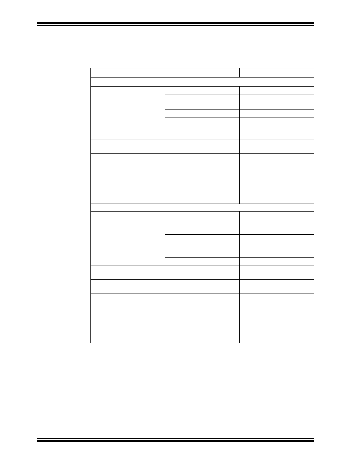
DOCUMENTATION CONVENTIONS
Description Represents Examples
Arial font:
Italic chara c ters Referenced books MPLAB
Emphasized text ...is the only compiler...
Initial caps A window the Output window
A dialog the Settings dialog
A menu selection select Enable Programmer
Quotes A field name in a window or
dialog
Underlined, italic text with
right angle bracket
Bold characters A dialog button Click OK
N‘Rnnnn A number in verilog format,
Te xt in angle brackets < > A key on the keyboard Press <Enter>, <F1>
Courier New font:
Plain Courier New Sample source code #define START
Italic Courier New A variable argument file.o, where file can be
Square brackets [ ] Optional arguments mcc18 [options] file
Curly brackets and pipe
character: { | }
Ellipses... Replaces r epeated text var_name [,
A menu path File>Save
A tab Click the Power tab
where N is the tota l number of
digits, R is th e radi x and n is a
digit.
Filenames autoexec.bat
File paths c:\mcc18\h
Keywords _asm, _endasm, static
Command-line options -Opa+, -Opa-
Bit values 0, 1
Constants 0xFF, ‘A’
Choice of mut ually exclus ive
arguments; an OR selection
Represents code supplied by
user
“Save project before build”
4‘b0010, 2‘hF1
any valid filename
[options]
errorlevel {0|1}
var_name...]
void main (void)
{ ...
}
®
IDE User’s Guide
WARRANTY REGISTRATION
Please complete the enclosed Warranty Registration Card and mail it promptly. Sending in the Warranty Registration Card entitles users to receive new product updates.
Interim software releases are available at the Microchip web site.
DS50002447A-page 8 2015 Microchip Technology Inc.
Page 9

RECOMMENDED READING
This user’s guide describes how to use the HV583 128-Channel High-Voltage Driver
IC Evaluation Board. Other useful documents are listed below. The following Microchip
documents are available and recommended as supplemental reference resources.
• HV583 Data Sheet – “128-Channel Serial to Parallel Converter with Push-Pull
Outputs” (DS20005461).
Additional documentation (including schematic and code samples) is available under
the PIC32 Starter Kit (DM320001) section on the web site.
THE MICROCHIP WEB SITE
Microchip provides online support via our web site at www.microchip.com. This
web site is used as a means to make files and information easily available to
customers. Accessible by using your favorite Internet browser, the web site contains
the following information:
• Product Support – Data sheets and errata, application notes and sample
programs, design resources, user’s guides and hardware support documents,
latest software releases and archived software
• General Technical Support – Frequently Asked Questions (FAQs), technical
support requests, online discussion groups, Microchip consultant program
member listing
• Business of Microchip – Product selector and ordering guides, latest Microchip
press releases, listing of seminars and events, listings of Microchip sales offices,
distributors and factory representatives
Preface
DEVELOPMENT SYSTEMS CUSTOMER CHANGE NOTIFICATION SERVICE
Microchip’s custom er not ifi cati on service h elp s kee p cust omer s current on M icrochi p
products. Subscribers will rece ive e-mail notification whenever there are chang es, updates,
revisions or errata rela ted to a spec ified prod uct famil y or developme nt tool of interest.
To register, access the Microchip web site at www.microchip.com, click on Customer
Change Notification and follow the registration instructions.
The Development Systems product group categories are:
• Compilers – The latest info rmatio n on Microc hip C comp ilers, as semblers , linker s
and other language tools. These include all MPLAB
assemblers (including MPASM™ assembler); all MPLAB linkers (including
MPLINK™ object linker); and all MPLAB librarians (including MPLIB™
object librarian).
• Emulators – The latest information on Microchip in-circuit emulators.This
includes the MPLAB REAL ICE™ and MPLAB ICE 2000 in-circuit emulators.
• In-Circuit Debuggers – The latest information on the Microchip in-circuit
debuggers. This includes MPLAB ICD 3 in-circuit debuggers and PICkit™ 3
debug express.
• MPLAB IDE – The latest information on Microchip MPLAB IDE, the Windows
Integrated Development Environment for development systems tools. This list is
focused on the MPLAB IDE, MPLAB IDE Project Manager, MPLAB Editor and
MPLAB SIM simulator, as well as general editing and debugging features.
• Programmers – The latest information on Microchip programmers. These include
production programmers such as MPLAB REAL ICE in-circuit emulator, MPLAB
ICD 3 in-circuit debugger and MPLAB PM3 device programmers. Also included
are nonproduction development programmers, such as PICkit 2 and 3.
®
C compilers; all MPLAB
®
2015 Microchip Technology Inc. DS50002447 A-page 9
Page 10

HV583 128-Channel High-Voltage Driver IC Evaluation Board User’s Guide
CUSTOMER SUPPORT
Users of Microchip products can receive assistance through several channels:
• Distributor or Representative
• Local Sales Office
• Field Application Engineer (FAE)
• Technical Support
Customers should contact their distributor, representative or field application engineer
(FAE) for support. Local sales offices are also available to help customers. A listing of
sales offices and locations is included in the back of this document.
Technical support is available through the web site at:
http://www.microchip.com/support
DOCUMENT REVISION HISTORY
Revision A (December 2015)
• Initial release of this documen t.
DS50002447A-page 10 2015 Microchip Technology Inc.
Page 11

Chapter 1. Product Overview
1.1 INTRODUCTION
This chapter covers the following topics:
• HV583 Device Overview
• HV583 Evaluation Board Overview
• HV583 Evaluation Board Kit Contents
1.2 HV583 DEVICE OVERVIEW
The HV583 is a unipolar 128-channel, low-voltage serial to high-voltage parallel
converter with push-pull outputs, dedicated to printer driver and plasma display
applications. The device has been designed for applications that require high channel
count and high output voltage swing (0-80V) with current sinking and sourcing
capabilities of 30 mA.
The device consists of four parallel 32-bit Shift registers, a 128-bit latch and
128 high-voltage outputs. The 32-bit Shift registers can operate up to a 40 MHz speed
rate, allowing for fast data update. The parallel arrangement of the registers permits
four times the speed of a single register, providing a fast update rate for the 128 output
channels. Data flow can be shifted from a clockwise to a counterclockwise direction via
the DIR pin. All high-voltage outputs can be forced to a low-level, high-level or
high-impedance state (high Z) through the OL
HV583
128-CHANNEL HIGH-VOLTAGE DRIVER IC
EVALUATION BOARD USER’S GUIDE
, OH and OE pins, respectively.
1.3 HV583 EVALUATION BOARD OVERVIEW
The HV583 128-Channel High-Voltage Driver IC Evaluation Board facilitates the quick
implementation for display and printer driver applications with its flexible input/output
connection interface.
The evaluation board is designed to be operated together with the Microchip
T echnology PIC32 Starter Kit (DM320001) or with a generic signal pattern generator via
the dedicated J5 pin header connector (see Figure 1-1).
There are 32 test point pads corresponding to the first 32-bit register (D1A/D1B) that
control the high-voltage outputs: HV
with the test point pads to facilitate the analysis of the high-voltage output channels.
Refer to Figure 1-1 and to the HV583 Data Sheet.
All output channels are available via a 160-position, high-density array female
connector, where only 128 positions are used (refer to the Evaluation Board –
Schematic in Appendix A. “Schematic and Layouts” for more details).
OUT
0, 4, 8...124. Ground pads are provided along
2015 Microchip Technology Inc. DS50002447A-page 11
Page 12

HV583 128-Channel High-Voltage Driver IC Evaluation Board User’s Guide
POWER CONNECT
128-it
>atch
VDD
VPP
HV
OUT
0
HV
OUT
127
D
0
D
1
D
2
D
3
D
4
D
5
D
6
D
7
Q
0
Q
1
Q
2
Q
3
Q
4
Q
5
Q
6
Q
7
D
124
D
125
D
126
D
127
Q
124
Q
125
Q
126
Q
127
PGND
DGND
D1B
D1A
D2B
D2A
D3B
D3A
D4B
D4A
CLK
RST
LE
OH
OL
OE
DIR
32-it
^hift
Zegister
32-it
^hift
Zegister
32-it
^hift
Zegister
32-it
^hift
Zegister
1
2
3
4
5
6
Legend:
1
=
FX10A-120S/12-SV(71) connector (J2) for PIC32 Starter Kit (DM320001), not inclu ded
2
=
Header connector for (generic) signal pattern generator (J5), not installed
3
=
HV583 169-Ball TFBGA package
4=Power connection pin header
5
=
32 HV
OUT
n test points and ground pads
6
=
160-posit ion, high-density array female connector
The HV583 contains four parallel 32-bit Shift registers. Each 32-bit Shift register features two po rts that ca n be set as ei ther i nput s or out put s by co ntrol ling t he DIR pin, a s
shown in the following list:
• setting the DIR pin high enables the DnA pins as inputs and the DnB pins as
outputs (counterclockwise input data)
• setting the DIR pin low configures DnB pins as inputs and DnA pins as outputs
(clockwise input data)
Shunt (zero Ohm) resistors are placed right after the pin header connectors (D1B to
D4B) to facilitate the adjustment of the Input registers in any desired manner.
Note: The HV583 128-Channel High-Voltage Driver IC Evaluation Board comes
equipped with shunt resistors only on the DnB pins. Shunt resistors are not
installed on the DnA pins.
1.3.1 HV583 Evaluation Board Block Diagram
Figure 1-1 presents the HV583 128-Channel High-Voltage Driver IC Evaluation Board
block diagram with the main sections labeled and explained.
FIGURE 1-1: HV583 128-Channel High-Voltage Driver IC Evaluation Boa rd Bloc k Diagr am.
DS50002447A-page 12 2015 Microchip Technology Inc.
Page 13

1.4 HV583 EV ALUATION BOARD KIT CONTE NTS
The HV583 128-Channel High-Voltage Driver IC Evaluation Board Kit includes:
• HV583 128-Channel High-Voltage Driver IC Evaluation Board (ADM00677)
• Important Information Sheet
Product Overview
FIGURE 1-2: HV583 128-Channel High-Voltage Driver IC Evaluation Boar d – Top View.
2015 Microchip Technology Inc. DS50002447A-page 13
Page 14

HV583 128-Channel High-Voltage Driver IC Evaluation Board User’s Guide
NOTES:
DS50002447A-page 14 2015 Microchip Technology Inc.
Page 15

Chapter 2. Installation and Operation
2.1 GETTING STARTED
The HV583 128-Channel High-Voltage Driver IC Evaluation Board is fully assembled
and tested.
2.1.1 Tools Required for Operation
• A low DC power supply for VDD (and VDD_PIC) that can produce 5V
• A high DC power supply for V
• A logic signal driver: PIC32 Starter Kit (DM320001) or a generic signal pattern
generator
• An oscilloscope and/or a multimeter to observe waveforms and measure electrical
parameters.
2.2 SETUP PROCEDURE
HV583
128-CHANNEL HIGH-VOLTAGE DRIVER IC
EVALUATION BOARD USER’S GUIDE
with a voltage range up to +80V
PP
To prepare the HV583 128-Channel High-Voltage Driver IC Evaluation Board for
operation, the following steps must be followed:
WARNING
Read the HV583 128-Channel High-Voltage Driver IC Evaluation Board User’s
Guide (this document) fully before proceeding to board setup.
1. Connect the power supplies by following the steps indicated by this power-up
sequence:
a) Connect GND
b) Apply V
c) Connect VDD_PIC (if PIC32 Starter Kit is mounted and used)
d) Set logic input signals to a known state
e) Apply V
Note 1: If the PIC32 Starter Kit is used and connected to the USB debug cable,
Note: To power down the board, follow the reverse order of the power-up
DD
PP
there is no need to power the VDD_PIC pin.
sequence.
(1)
2015 Microchip Technology Inc. DS50002447A-page 15
Page 16

HV583 128-Channel High-Voltage Driver IC Evaluation Board User’s Guide
Board Power-up
Sequence:
1. GND
2. V
DD
3. VDD_PIC
4. Logic signals
to known state
5. V
PP
FIGURE 2-1: Board Power-up Sequence.
2. Apply the voltage settings by following the steps indicated in Table 2-1.
TABLE 2-1: VOLTAGE SETTINGS
Step Terminal Name Description
1 GND Ground
2V
3 VDD_PIC 5.0V, power supply for PIC32 Starter Kit
4VPP+15V to +80V, high-voltage power supply for all HV
Note 1: If the PIC32 Starter Kit is used and not connected to the USB debug cable.
DD
5.0V, logic power supply for HV583
After following the power-up sequence and applying the voltage settings correctly, the
evaluation board is ready to operate.
The HV583 128-Channel High-Voltage Driver IC Evaluation Board can be driven by a
generic signal pattern generator or by the suggested PIC32 Starter Kit (DM320001).
Section 2.3 “Using the Evaluation Board with a Generic Logic Signal Pattern
Generator” and Section 2.4 “Using the Evaluation Board with the PIC32 Starter
Kit (DM320001)” elaborate on the operation and evaluation process in detail.
(1)
OUT
n
DS50002447A-page 16 2015 Microchip Technology Inc.
Page 17

Installation and Operation
J5 Pin
Header Connector
2.3 USING THE EVALUATION BOARD WITH A GENERIC LOGIC SIGNAL PATTERN GENERATOR
2.3.1 Introduction
The HV583 128-Channel High-Voltage Driver IC Evaluation Board can be operated by
a generic logic signal pattern generator, or by any signal driver, via the J5 pin header
connector (pin header not installed).
FIGURE 2-2: J5 Pin Header Connector.
The user must ensure the minimum DC and AC electrical parameters are achieved by
the signal pattern generator. For more information, refer to the HV583 data sheet
(DS20005461).
2.3.2 Operating the Evaluation Board
When operating the evaluation board with a generic logic signal pattern generator, the
VDD_PIC pin should not be powered on. The VDD_PIC pin is an optional power pin
used only for the PIC32 Starter Kit (DM320001).
In case a read operation is required for the signal driver, it is recommended to operate
the pattern generator at the same voltage potential as the evaluation board (V
for instance, the signal pattern generator is operating at a lower voltage (e.g., 3.3V)
than that of the evaluation board (5.0V), this will cause the ESD protection diodes of
the signal generator to forward bias and possibly damage the board.
If a read-back operation is required by the generic signal pattern generato r (or
by any signal driver), the operational voltage level of the logic signals must be
equal to the voltage potential of the evaluation board (V
WARNING
DD
). If,
DD
).
2015 Microchip Technology Inc. DS50002447A-page 17
Page 18

HV583 128-Channel High-Voltage Driver IC Evaluation Board User’s Guide
CLK
D1B
LE
t
SU1
= 5 ns (MIN)
OE
DIR
D2B, D3B, D4B
RST
th1= 5 ns (MIN)
HV
OUT
124, HV
OUT
116
HV
OUT
108
Rest of channels OFF
32123456 3031
Data Transmission
V
OH
V
OL
t
pHZ
V
IH
V
IL
V
IH
V
IL
V
IH
V
IL
V
IH
V
IL
V
IH
V
IL
V
IH
V
IL
V
IH
V
IL
V
IH
V
IL
t
pLH
t
r
Time: 0
OH,OL
Figure 2-3 presents the logic diagram of a sample data transmission for testing and
understanding the functionality of the HV583.
FIGURE 2-3: Sample Data Transmission Timing Diagram.
DS50002447A-page 18 2015 Microchip Technology Inc.
Page 19

Installation and Operation
FX10A-120S/12-SV(71)
J2 Connector
2.4 USING THE EVALUATION BOARD WITH THE PIC32 STARTER KIT (DM320001)
2.4.1 Introduction
The HV583 128-Channel High-Voltage Driver IC Evaluation Board can be operated by
the Microchip PIC32 Starter Kit (DM320001) via the FX10A-120S/12-SV(71)
connector, J2 (see Figure 2-4).
Note: Several PIC32 Starter Kits might be compatible with the HV583 Evaluation
Board, but only the DM320001 is supported with code.
2.4.2 Software Requirements
In order to operate the PIC32 Starter Kit, the MPLAB® X IDE software and MPLAB®
XC32 compiler must be installed in the user’s system. Software and compilers are
available for download on the Microchip web site at: www.microchip.com.
For detailed information regarding the installation and usage of MPLAB
refer to the “MPLAB
®
X IDE User’s Guide” (DS50002027).
2.4.3 Connecting the PIC32 Starter Kit to the HV583 Evaluation Board
Mount the PIC32 Starter Kit (DM320001) onto the J2 connector before powering up the
board. Follow the power-up sequence and apply the voltage settings indicated in
Section 2.2 “Setup Procedure”.
X IDE software,
FIGURE 2-4: FX10A-120S/12-SV(71 ) Conn ector, J2.
2015 Microchip Technology Inc. DS50002447A-page 19
Page 20

HV583 128-Channel High-Voltage Driver IC Evaluation Board User’s Guide
TRASMIT DATA
TO
H
VOUT
n
MAKE ALL H
VOUT
n
LOW
START
INITIALIZE PORTS
NO
YES
SW1?
YES
NO
SW2?
SW3?
YES
NO
YES
MAKE ALL H
VOUT
n
HIGH
NO
ANY BUTTON
PRESS
2.4.4 PIC32 Starter Kit Software Code
The source code for driving the HV583 128-Channel High-Voltage Driver IC Evaluation
Board, PIC32_HV583.x, is available for download on the Microchip web site. The
objective of the code is to provide a starting platform for utilizing the HV583 evaluation
board.
The code flowchart is presented in Figure 2-5.
FIGURE 2-5: Program Code Flowchart.
DS50002447A-page 20 2015 Microchip Technology Inc.
Page 21

Installation and Operation
Table 2-2 provides a summary of the software code operation.
TABLE 2-2: SOFTWARE CODE OPERATION
Switch Description
SW1 LED 1 turns on, data is sent to Input registers, D1B, D2B, D3B and D4B
SW2 LED 2 turns on, makes all (HV
SW3 LED 3 turns on, makes all (HV
Note 1: Push button switches are located on the PIC32 Starter Kit; see Figure 2-6 and
Section 2.4.6 “Modifying the Control Signals and Data in the Code”.
n) High-Voltage channels low (GND)
OUT
n) High-Voltage channels high (VPP)
OUT
(1)
FIGURE 2-6: HV583 128-Channel High-Voltage Driver IC Evaluation Board with PIC32 Starter Kit (DM320001) Connected on J2 – Top View.
2.4.5 Programming the PIC32 Starter Kit
This section assumes that the MPLAB X IDE software and the MPLAB XC32 compiler
are installed on the user’s system, and the PIC32 Starter Kit is connected to the PC via
the USB debug cable.
To load the PIC32_HV583.x code, follow these steps:
1. Open the MPLAB X IDE and then the PIC32_HV583.x program code.
2. Select the Clean and Build Project icon ( ). Ignore warning messages.
3. Select the Make and Program Device icon ( ).
2015 Microchip Technology Inc. DS50002447A-page 21
Page 22

HV583 128-Channel High-Voltage Driver IC Evaluation Board User’s Guide
FIGURE 2-7: MPLAB® X IDE Workspace.
2.4.6 Modifying the Control Signals and Data i n the Code
To modify the control signals and the data to be sent to the HV583, open the
HV583_defines.h file located under the Header Files folder.
To change the control signals, LE, OE, DIR, RST, OH
file labeled, INPUT CONTROL SIGNALS (see Figure 2-8), and modify accordingly.
Data transmission is controlled by pressing the push button switches on the PIC32
Starter Kit (see Figure 2-6). The user can select one of three available cases:
• HV583_CASE_1_ENABLE and HV583_CASE_1_DISABLE control the data
transmission; selectable by pr es si ng SW 1.
• HV583_CASE_2_ENABLE makes all HV
n channels low; selectable by
OUT
pressing SW2.
• HV583_CASE_3_ENABLE makes all HV
n channels high; selectable by
OUT
pressing SW3.
and OL, locate the section in the
FIGURE 2-8: Input Control Signals: LE, OE, DIR, RST, OH
and OL.
To change the data to be sent to the Input registers of the HV583, scroll to the bottom
of the file, locate the section, DATA TO SEND TO REGISTERS, and change the values
as desired (see Figure 2-9).
The HV583 consists of four 32-bit Shift registers.
The first 32-bit register uses D1A/D1B as input/output pins. The second register uses
D2A/D2B, the third register uses D3A/D3B and the fourth register uses D4A/D4B.
In the code, DATA_1, corresponds to the first bit of data to be sent to all of the four
registers. The Least Significant Bit (LSB) corresponds first to D1A/D1B, second to
D2A/D2B, third to D3A/D3B, and fourth to D4A/D4B.
DS50002447A-page 22 2015 Microchip Technology Inc.
Page 23

Installation and Operation
FIGURE 2-9: Data to Send to the HV583 Input Registers.
The code flow is specified in the main.c file (see Figure 2-7) located under the Source
Files folder.
NOTICE
By default, the code provided sends data into the DnB Input registers of the HV583.
WARNING
The PIC32 Starter Kit (DM320001) cannot be used to read data back from the
HV583 Evaluation Board because of the difference in the logic voltage level:
3.3V (PIC32) vs. 5.0V (V
in the PIC32 board to forward bias and possibly damage the board.
2015 Microchip Technology Inc. DS50002447A-page 23
). If used, this will cause the ESD protection diodes
DD
Page 24

HV583 128-Channel High-Voltage Driver IC Evaluation Board User’s Guide
NOTES:
DS50002447A-page 24 2015 Microchip Technology Inc.
Page 25

Appendix A. Schematic and Layouts
A.1 INTRODUCTION
This appendix contains the following layouts and schematic for the HV583
128-Channel High-Voltage Driver IC Evaluation Board (ADM00677):
• Evaluation Board – Schematic
• Evaluation Board – Top Silk
• Evaluation Board – Top Copper and Silk
• Evaluation Board – Top Copper
• Evaluation Board – Ground Plane
• Evaluation Board – Mid Layer 1
• Evaluation Board – Mid Layer 2
• Evaluation Board – Power Plane
• Evaluation Board – Bottom Copper
• Evaluation Board – Bottom Copper and Silk
• Evaluation Board – Bottom Silk
HV583
128-CHANNEL HIGH-VOLTAGE DRIVER IC
EVALUATION BOARD USER’S GUIDE
2015 Microchip Technology Inc. DS50002447A-page 25
Page 26

DS50002447A-page 26 2015 Microchip Technology Inc.
HV583
HV583 128-Channel High-Voltage Driver IC Evaluation Board User’s Guide
A.2 EVALUATION BOARD – SCHEMATIC
Page 27

A.3 EVALUATION BOARD – TOP SILK
Schematic and Layouts
A.4 EVALUATION BOARD – TOP COPPER AND SILK
2015 Microchip Technology Inc. DS50002447A-page 27
Page 28

HV583 128-Channel High-Voltage Driver IC Evaluation Board User’s Guide
A.5 EVALUATION BOARD – TOP COPPER
A.6 EVALUATION BOARD – GROUND PLANE
DS50002447A-page 28 2015 Microchip Technology Inc.
Page 29

A.7 EVALUATION BOARD – MID LAYER 1
Schematic and Layouts
A.8 EVALUATION BOARD – MID LAYER 2
2015 Microchip Technology Inc. DS50002447A-page 29
Page 30

HV583 128-Channel High-Voltage Driver IC Evaluation Board User’s Guide
A.9 EVALUATION BOARD – POWER PLANE
A.10 EVALUATION BOARD – BOTTOM COPPE R
DS50002447A-page 30 2015 Microchip Technology Inc.
Page 31

Schematic and Layouts
A.11 EVALUATION BOARD – BOTTOM COPPER AND SILK
A.12 EVALUATION BOARD – BOTTOM SILK
2015 Microchip Technology Inc. DS50002447A-page 31
Page 32

HV583 128-Channel High-Voltage Driver IC Evaluation Board User’s Guide
NOTES:
DS50002447A-page 32 2015 Microchip Technology Inc.
Page 33

HV583
128-CHANNEL HIGH-VOLTAGE DRIVER IC
EVALUATION BOARD USER’S GUIDE
Appendix B. Bill of Materials (BOM)
TABLE B-1: BILL OF MATERIALS (BOM)
Qty. Designator Description Manufacturer Part Number
1 C1 Ceramic Capacitor, 1 µF, 100V AVX Corporation 12061C105KAT2A
1 C2 Ceramic Capacitor, 0.1 µF, 25V AVX Corporation 06033C104JAT2A
1 J1 160 Position High-Density Array
Connector, Female
1 J2 Board-to-Board High-S peed Connector ,
120 Positions, w/Post, SMD
1 J3 Connector Header, 4 Positions,
100", SGL, Gold
4 GND Connector PC Pin, Circular,
0.030 Diameter, Gold
6 N/A Rubber Bumper Square, 0.5"L x 0.5"W,
Black
1 PCB HV583 128-Channel High-Voltage
Driver IC Evaluation Board – Printed
Circuit Board
4 R1, R3, R5,
R7
4 R2, R4, R6, R8Resistor, SMD, 0.0Ohm, Jump er,
1 U1 HV583, Unipolar 128-Channel
Note: The component s listed in this Bill of Materia ls are repre senta tive of the PCB assemb ly. The released BOM
used in manufacturing uses all RoHS-compliant components.
DO NOT POPULATE ——
1/10W
Low-voltage Serial to
High-Voltage Parallel Converter with
Push-Pull Outputs
Molex®, LLC 0465574145
Hirose Electric Co. Ltd. FX10A-120S/12-SV(71)
Samtec Inc. TSW-104-07-G-S
Mill-Max Manufacturing
Corp.
3M SJ-5518 (BLACK)
— 04-10436
Stackpole Electronics,
Inc.
Microchip Technology
Inc.
3132-0-00-15-00-00-08-0
RMCF0603ZT0R00
HV583GA-G
2015 Microchip Technology Inc. DS50002447A-page 33
Page 34

HV583 128-Channel High-Voltage Driver IC Evaluation Board User’s Guide
NOTES:
DS50002447A-page 34 2015 Microchip Technology Inc.
Page 35

Appendix C. HV583 Typical Waveforms
5V/Div
5V/Div
5V/Div
5V/Div
Time = 800 ns/Div
C.1 INTRODUCTION
Waveforms presented in this section correspond to two consecutive data
transmissions: Transmission 1 and Transmission 2. No load is connected to the output
channels.
C.1.1 Transmission 1
HV583
128-CHANNEL HIGH-VOLTAGE DRIVER IC
EVALUATION BOARD USER’S GUIDE
Turns on HV
124, 116, 108 and 0. Turns off the rest of the HV
OUT
channels.
OUT
The control signals not shown in the waveforms have the states listed in Table C-1:
TABLE C-1: TRANSMISSION 1: CONTROL SIGNAL STATES
Signal State
DIR Low
RST Low
OH
OL
D2B Low
D3B Low
D4B Low
High
High
FIGURE C-1: Transmission 1.
2015 Microchip Technology Inc. DS50002447A-page 35
Page 36

HV583 128-Channel High-Voltage Driver IC Evaluation Board User’s Guide
5V/Div
5V/Div
5V/Div
40V/Div
Time = 800 ns/Div
20V/Div
5V/Div
Time = 100 ns/Div
FIGURE C-2: Transmission 1: HV
124 Displayed Instead of OE.
OUT
FIGURE C-3: Transmission 1: Zoom Version, LE and HV
OUT
124.
DS50002447A-page 36 2015 Microchip Technology Inc.
Page 37

C.1.2 Transmission 2
5V/Div
5V/Div
5V/Div
5V/Div
Time = 800 ns/Div
HV583 Typical Waveforms
Turns on HV
channels. This transmission illustrates the turn-off transition for HV
a high level (V
116, 108 and 0. Turns off HV
OUT
) due to Transmission 1.
PP
124 and the rest of the HV
OUT
OUT
OUT
124, which i s at
The control signals not shown in the waveforms have the states listed in Table C-2:
TABLE C-2: TRANSMISSION 2: CONTROL SIGNAL STATES
Signal State
DIR Low
RST Low
OH
OL
D2B Low
D3B Low
D4B Low
High
High
FIGURE C-4: Transmission 2.
2015 Microchip Technology Inc. DS50002447A-page 37
Page 38

HV583 128-Channel High-Voltage Driver IC Evaluation Board User’s Guide
5V/Div
5V/Div
5V/Div
40V/Div
Time = 800 ns/Div
20V/Div
5V/Div
Time = 100 ns/Div
FIGURE C-5: Transmission 2: HV
124 Displayed Instead of OE.
OUT
FIGURE C-6: Transmission 2: Zoom Version, LE and HV
OUT
124.
DS50002447A-page 38 2015 Microchip Technology Inc.
Page 39

NOTES:
HV583 Typical Waveforms
2015 Microchip Technology Inc. DS50002447A-page 39
Page 40

Worldwide Sales and Service
AMERICAS
Corporate Office
2355 West Chandler Blvd.
Chandler, AZ 85224-6199
Tel: 480-792-7200
Fax: 480-792-7277
Te chn ica l Support:
http://www.microchip.com/
support
Web Address:
www.microchip.com
Atlanta
Duluth, GA
Tel: 678-957-9614
Fax: 678-957-1455
Austin, TX
Tel: 512-257-3370
Boston
Westborough, MA
Tel: 774-760-0087
Fax: 774-760-0088
Chicago
Itasca, IL
Tel: 630-285-0071
Fax: 630-285-0075
Cleveland
Independence, OH
Tel: 216-447-0464
Fax: 216-447-0643
Dallas
Addison, TX
Tel: 972-818-7423
Fax: 972-818-2924
Detroit
Novi, MI
Tel: 248-848-4000
Houston, TX
Tel: 281-894-5983
Indianapolis
Noblesville, IN
Tel: 317-773-8323
Fax: 317-773-5453
Los Angeles
Mission Viejo, CA
Tel: 949-462-9523
Fax: 949-462-9608
New Yor k , NY
Tel: 631-435-6000
San Jose, CA
Tel: 408-735-9110
Canada - Toronto
Tel: 905-673-0699
Fax: 905-673-6509
ASIA/PACIFIC
Asia Pacific Office
Suites 3707-14, 37th Floor
Tower 6, The Gateway
Harbour City, Kowloon
Hong Kong
Tel: 852-2943-5100
Fax: 852-2401-3431
Australia - Sydney
Tel: 61-2-9868-6733
Fax: 61-2-9868-6755
China - Beijing
Tel: 86-10-8569-7000
Fax: 86-10-8528-2104
China - Chengdu
Tel: 86-28-8665-5511
Fax: 86-28-8665-7889
China - Chongqing
Tel: 86-23-8980-9588
Fax: 86-23-8980-9500
China - Dongguan
Tel: 86-769-8702-9880
China - Hangzhou
Tel: 86-571-8792-8115
Fax: 86-571-8792-8116
China - Hong Kong SAR
Tel: 852-2943-5100
Fax: 852-2401-3431
China - Nanjing
Tel: 86-25-8473-2460
Fax: 86-25-8473-2470
China - Qingdao
Tel: 86-532-8502-7355
Fax: 86-532-8502-7205
China - Shanghai
Tel: 86-21-5407-5533
Fax: 86-21-5407-5066
China - Shenyang
Tel: 86-24-2334-2829
Fax: 86-24-2334-2393
China - Shenzhen
Tel: 86-755-8864-2200
Fax: 86-755-8203-1760
China - Wuhan
Tel: 86-27-5980-5300
Fax: 86-27-5980-5118
China - Xian
Tel: 86-29-8833-7252
Fax: 86-29-8833-7256
ASIA/PACIFIC
China - Xiamen
Tel: 86-592-2388138
Fax: 86-592-2388130
China - Zhuhai
Tel: 86-756-3210040
Fax: 86-756-3210049
India - Bangalore
Tel: 91-80-3090-4444
Fax: 91-80-3090-4123
India - New Delhi
Tel: 91-11-4160-8631
Fax: 91-11-4160-8632
India - Pune
Tel: 91-20-3019-1500
Japan - Osaka
Tel: 81-6-6152-7160
Fax: 81-6-6152-9310
Japan - Tokyo
Tel: 81-3-6880- 3770
Fax: 81-3-6880-3771
Korea - Daegu
Tel: 82-53-744-4301
Fax: 82-53-744-4302
Korea - Seoul
Tel: 82-2-554-7200
Fax: 82-2-558-5932 or
82-2-558-5934
Malaysia - Kuala Lumpur
Tel: 60-3-6201-9857
Fax: 60-3-6201-9859
Malaysia - Penang
Tel: 60-4-227-8870
Fax: 60-4-227-4068
Philippines - Manila
Tel: 63-2-634-9065
Fax: 63-2-634-9069
Singapore
Tel: 65-6334-8870
Fax: 65-6334-8850
Tai wan - Hsin Chu
Tel: 886-3-5778-366
Fax: 886-3-5770-955
Taiwan - Kaohsiung
Tel: 886-7-213-7828
Taiwan - Taipei
Tel: 886-2-2508-8600
Fax: 886-2-2508-0102
Thailand - Bangkok
Tel: 66-2-694-1351
Fax: 66-2-694-1350
EUROPE
Austria - Wels
Tel: 43-7242-2244-39
Fax: 43-7242-2244-393
Denmark - Copenhagen
Tel: 45-4450-2828
Fax: 45-4485-2829
France - Paris
Tel: 33-1-69-53-63-20
Fax: 33-1-69-30-90-79
Germany - Dusseldorf
Tel: 49-2129-3766400
Germany - Karlsruhe
Tel: 49-721-625370
Germany - Munich
Tel: 49-89-627-144-0
Fax: 49-89-627-144-44
Italy - Milan
Tel: 39-0331-742611
Fax: 39-0331-466781
Italy - Venice
Tel: 39-049-7625286
Netherlands - Drunen
Tel: 31-416-690399
Fax: 31-416-690340
Poland - Wars a w
Tel: 48-22-3325737
Spain - Madrid
Tel: 34-91-708-08-90
Fax: 34-91-708-08-91
Sweden - Stockholm
Tel: 46-8-5090-4654
UK - Wokingham
Tel: 44-118-921-5800
Fax: 44-118-921-5820
07/14/15
DS50002447A-page 40 2015 Microchip Technology Inc.
 Loading...