

Page 1
Humidity Sensor
PICtail™ Demo Board
User’s Guide
© 2005 Microchip Technology Inc. DS51594A
Page 2

Note the following details of the code protection feature on Microchip devices:
• Microchip products meet the specification contained in their particular Microchip Data Sheet.
• Microchip believes that its family of products is one of the most secure families of its kind on the market today, when used in the
intended manner and under normal conditions.
• There are dishonest and possibly illegal methods used to breach the code protection feature. All of these methods, to our
knowledge, require using the Microchip products in a manner outside the operating specifications contained in Microchip’s Data
Sheets. Most likely, the person doing so is engaged in theft of intellectual property.
• Microchip is willing to work with the customer who is concerned about the integrity of their code.
• Neither Microchip nor any other semiconductor manufacturer can guarantee the security of their code. Code protection does not
mean that we are guaranteeing the product as “unbreakable.”
Code protection is constantly evolving. We at Microchip are committed to continuously improving the code protection features of our
products. Attempts to break Microchip’s code protection feature may be a violation of the Digital Millennium Copyright Act. If such acts
allow unauthorized access to your software or other copyrighted work, you may have a right to sue for relief under that Act.
Information contained in this publication regarding device
applications and the like is provided only for your convenience
and may be superseded by updates. It is your responsibility to
ensure that your application meets with your specifications.
MICROCHIP MAKES NO REPRESENTATIONS OR WARRANTIES OF ANY KIND WHETHER EXPRESS OR IMPLIED,
WRITTEN OR ORAL, STATUTORY OR OTHERWISE,
RELATED TO THE INFORMATION, INCLUDING BUT NOT
LIMITED TO ITS CONDITION, QUALITY, PERFORMANCE,
MERCHANTABILITY OR FITNESS FOR PURPOSE.
Microchip disclaims all liability arising from this information and
its use. Use of Microchip’s products as critical components in
life support systems is not authorized except with express
written approval by Microchip. No licenses are conveyed,
implicitly or otherwise, under any Microchip intellectual property
rights.
Trademarks
The Microchip name and logo, the Microchip logo, Accuron,
dsPIC, K
EELOQ, microID, MPLAB, PIC, PICmicro, PICSTART,
PRO MATE, PowerSmart, rfPIC, and SmartShunt are
registered trademarks of Microchip Technology Incorporated
in the U.S.A. and other countries.
AmpLab, FilterLab, Migratable Memory, MXDEV, MXLAB,
PICMASTER, SEEVAL, SmartSensor and The Embedded
Control Solutions Company are registered trademarks of
Microchip Technology Incorporated in the U.S.A.
Analog-for-the-Digital Age, Application Maestro, dsPICDEM,
dsPICDEM.net, dsPICworks, ECAN, ECONOMONITOR,
FanSense, FlexROM, fuzzyLAB, In-Circuit Serial
Programming, ICSP, ICEPIC, Linear Active Thermistor,
MPASM, MPLIB, MPLINK, MPSIM, PICkit, PICDEM,
PICDEM.net, PICLAB, PICtail, PowerCal, PowerInfo,
PowerMate, PowerTool, Real ICE, rfLAB, rfPICDEM, Select
Mode, Smart Serial, SmartTel, Total Endurance, UNI/O,
WiperLock and Zena are trademarks of Microchip Technology
Incorporated in the U.S.A. and other countries.
SQTP is a service mark of Microchip Technology Incorporated
in the U.S.A.
All other trademarks mentioned herein are property of their
respective companies.
© 2005, Microchip Technology Incorporated, Printed in the
U.S.A., All Rights Reserved.
Printed on recycled paper.
Microchip received ISO/TS-16949:2002 quality system certification for
its worldwide headquarters, design and wafer fabrication facilities in
Chandler and Tempe, Arizona and Mountain View, California in
October 2003. The Company’s quality system processes and
procedures are for its PICmicro
devices, Serial EEPROMs, microperipherals, nonvolatile memory and
analog products. In addition, Microchip’s quality system for the design
and manufacture of development systems is ISO 9001:2000 certified.
®
8-bit MCUs, KEELOQ
®
code hopping
DS51594A-page ii © 2005 Microchip Technology Inc.
Page 3

HUMIDITY SENSOR PICTAIL™
DEMO BOARD USER’S GUIDE
Table of Contents
Preface ........................................................................................................................... 1
Introduction............................................................................................................ 1
Document Layout .................................................................................................. 1
Conventions Used in this Guide ............................................................................ 2
Recommended Reading........................................................................................ 3
The Microchip Web Site ........................................................................................ 4
Customer Support ................................................................................................. 4
Document Revision History ................................................................................... 4
Chapter 1. Product Overview
1.1 Introduction ..................................................................................................... 5
1.2 Kit Contents .................................................................................................... 5
1.3 Humidity Sensor PICtail™ Demo Board ......................................................... 5
1.4 Associated Tools ............................................................................................ 7
1.5 Assembly Code Modules ................................................................................ 8
Chapter 2. Setup and Installation
2.1 Introduction ..................................................................................................... 9
2.2 Required Tools ............................................................................................... 9
2.3 Setting up the Humidity Sensor PICtail™ Demo Board ................................. 9
2.4 Connecting to Alternate Tools ...................................................................... 11
Chapter 3. Operation
3.1 Introduction ................................................................................................... 13
3.2 Configuring the Humidity Sensor PICtail™ Demo Board ............................. 13
3.3 Using the Humidity Sensor PC Program ...................................................... 13
3.4 Humidity Sensor Calibration ......................................................................... 15
Chapter 4. Modified Circuit
4.1 Introduction ................................................................................................... 17
4.2 The “Reduced Current” Circuit ..................................................................... 17
© 2005 Microchip Technology Inc. DS51594A-page iii
Page 4

Humidity Sensor PICtail™ Demo Board User’s Guide
Appendix A. Schematic and Layouts
A.1 Introduction .................................................................................................. 19
A.2 Highlights ..................................................................................................... 19
A.3 Demonstration Board Description ................................................................ 19
A.4 The “Reduced Current” Modification ............................................................ 20
A.5 Additional Comments ................................................................................... 20
Appendix B. Bill Of Materials (BOM)
B.1 Humidity Sensor PICtail™ Demo Board BOM ............................................. 25
B.2 BOM for Humidity Sensor and Other Capacitors in Box .............................. 26
B.3 BOM for “Reduced Current” Modifications ................................................... 26
Worldwide Sales and Service .....................................................................................28
DS51594A-page iv © 2005 Microchip Technology Inc.
Page 5

HUMIDITY SENSOR PICTAIL™
DEMO BOARD USER’S GUIDE
Preface
NOTICE TO CUSTOMERS
All documentation becomes dated, and this manual is no exception. Microchip tools and
documentation are constantly evolving to meet customer needs, so some actual dialogs
and/or tool descriptions may differ from those in this document. Please refer to our web site
(www.microchip.com) to obtain the latest documentation available.
Documents are identified with a “DS” number. This number is located on the bottom of each
page, in front of the page number. The numbering convention for the DS number is
“DSXXXXXA”, where “XXXXX” is the document number and “A” is the revision level of the
document.
INTRODUCTION
This chapter contains general information that will be useful to know before using the
Humidity Sensor PICtail™ Demo Board. Items discussed in this chapter include:
• Document Layout
• Conventions Used in this Guide
• Recommended Reading
• The Microchip Web Site
• Customer Support
• Document Revision History
DOCUMENT LAYOUT
This document describes how to use the Humidity Sensor PICtail™ Demo Board as a
development tool to emulate and debug firmware on a target board. The manual layout
is as follows:
• Chapter 1. “Product Overview” – This is an introduction to the Humidity Sensor
PICtail™ Demo Board. It covers the kit contents, associated tools and how they
work together.
• Chapter 2. “Setup and Installation” – Covers the initial set-up of the Humidity
Sensor PICtail™ Demo Board. It lists the required tools, shows how to connect
this board and demonstates how to verify the set-up.
• Chapter 3. “Operation” – This chapter discusses using the humidity sensor on
the PCB and using the software PC Application.
• Chapter 4. “Modified Circuit” – Gives the modifications necessary to increase
measurement resolution by a factor of 100 (see AN1016 for details)
• Appendix A. “Schematic and Layouts” – Gives detailed information on the
Humidity Sensor PICtail™ Demo Board. Includes detailed circuit explanation,
schematic and board layouts.
• Appendix B. “Bill Of Materials (BOM)” – Gives detailed information on the
Humidity Sensor PICtail™ Demo Board’s firmware.
© 2005 Microchip Technology Inc. DS51594A-page 1
Page 6

Humidity Sensor PICtail™ Demo Board User’s Guide
CONVENTIONS USED IN THIS GUIDE
This manual uses the following documentation conventions:
DOCUMENTATION CONVENTIONS
Description Represents Examples
Arial font:
Italic characters Referenced books MPLAB
Emphasized text ...is the only compiler...
Initial caps A window the Output window
A dialog the Settings dialog
A menu selection select Enable Programmer
Quotes A field name in a window or
dialog
Underlined, italic text with
right angle bracket
Bold characters A dialog button Click OK
N‘Rnnnn A number in verilog format,
Text in angle brackets < > A key on the keyboard Press <Enter>, <F1>
Courier New font:
Plain Courier New Sample source code #define START
Italic Courier New A variable argument file.o, where file can be
Square brackets [ ] Optional arguments mcc18 [options] file
Curly brackets and pipe
character: { | }
Ellipses... Replaces repeated text var_name [,
A menu path File>Save
A tab Click the Power tab
where N is the total number of
digits, R is the radix and n is a
digit.
Filenames autoexec.bat
File paths c:\mcc18\h
Keywords _asm, _endasm, static
Command-line options -Opa+, -Opa-
Bit values 0, 1
Constants 0xFF, ‘A’
Choice of mutually exclusive
arguments; an OR selection
Represents code supplied by
user
“Save project before build”
4‘b0010, 2‘hF1
any valid filename
[options]
errorlevel {0|1}
var_name...]
void main (void)
{ ...
}
®
IDE User’s Guide
DS51594A-page 2 © 2005 Microchip Technology Inc.
Page 7

RECOMMENDED READING
This user's guide describes how to use Humidity Sensor PICtail™ Demo Board. Other
useful documents are listed below and are recommended as supplemental reference
resources.
PICkit™ 2 Microcontroller Programmer User’s Guide (DS51553)
Contains instructions on how to use the PICkit 2 Microcontroller Programmer hardware
and software.
PICkit™ 1 Flash Starter Kit User’s Guide (DS40051)
Contains instructions on how to use the PICkit 1 Flash Starter Kit hardware and
software.
MPLAB
This user’s guide covers Microchip’s low cost, real-time debugger and programmer for
selected PICmicro
(DSCs).
AN1016, “Detecting Small Capacitive Sensors Using the MCP6291 and
PIC16F690 Devices” (DS01016)
Explains the functionality and design of this board’s circuit. Contains measurement
results.
MCP6291/2/3/4/5 Data Sheet (DS21812)
Gives detailed information on the MCP6291/2/3/4/5 Op Amps.
PIC16F685/687/689/690 Data Sheet (DS41262)
Gives detailed information on the microcontroller used on the Humidity Sensor PICtail™
Demo Board.
PIC16C745/765 Data Sheet (DS41124)
Gives detailed information on the PICmicro microcontroller used on the PICkit 1 Flash
Starter Kit.
®
ICD 2 In-Circuit Debugger User’s Guide (DS51331)
Preface
®
Microcontrollers (MCUs) and dsPIC® Digital Signal Controllers
The following document is available on the internet from the company listed, and is
recommended as a supplemental reference resource.
Humirel, “Relative Humidity Sensor HS1100LF / HS1101LF,” Data Sheet, Rev. C,
Sept. 2004.
Gives detailed information on Humirel’s (www.humirel.com) HS1101LF capacitive
relative humidity sensor.
© 2005 Microchip Technology Inc. DS51594A-page 3
Page 8

Humidity Sensor PICtail™ Demo Board User’s Guide
THE MICROCHIP WEB SITE
Microchip provides online support via our web site at www.microchip.com. This web
site is used as a means to make files and information easily available to customers.
Accessible by using your favorite Internet browser, the web site contains the following
information:
• Product Support – Data sheets and errata, application notes and sample
programs, design resources, user’s guides and hardware support documents,
latest software releases and archived software
• General Technical Support – Frequently Asked Questions (FAQs), technical
support requests, online discussion groups, Microchip consultant program
member listing
• Business of Microchip – Product selector and ordering guides, latest Microchip
press releases, listing of seminars and events, listings of Microchip sales offices,
distributors and factory representatives
CUSTOMER SUPPORT
Users of Microchip products can receive assistance through several channels:
• Distributor or Representative
• Local Sales Office
• Field Application Engineer (FAE)
• Technical Support
• Development Systems Information Line
Customers should contact their distributor, representative or field application engineer
(FAE) for support. Local sales offices are also available to help customers. A listing of
sales offices and locations is included in the back of this document.
Technical support is available through the web site at: http://support.microchip.com
DOCUMENT REVISION HISTORY
Revision A (December 2005)
• Initial Release of this Document.
DS51594A-page 4 © 2005 Microchip Technology Inc.
Page 9

Chapter 1. Product Overview
1.1 INTRODUCTION
The Printed Circuit Board (PCB) discussed in this user’s guide is described as follows:
HUMIDITY SENSOR PICTAIL™
DEMO BOARD USER’S GUIDE
• Order Number:
• Assembly Number:
•Board Name:
This board supports the capacitive humidity sensor application note AN1016. It
measures the capacitance of a relative humidity sensor (or capacitor) plugged into the
board. The on-board microcontroller sends the measured and calculated data to a PC
(Personal Computer) for display.
Items discussed in this chapter include:
• Kit Contents
• Humidity Sensor PICtail™ Demo Board
• Associated Tools
• Initial Set-up
1.2 KIT CONTENTS
• Humidity Sensor PICtail™ Demo Board – This is an assembled and tested
Printed Circuit Board (PCB).
• CD-ROM – Provided separately in the shipping box; it contains the files and
literature mentioned in this user’s guide.
• Humidity Sensor (HS1101LF) – Provided separately in the shipping box.
• Bag of Capacitors – Provided separately in the shipping box. These capacitors
are provided for the user’s convenience; they make it easy to try out this board’s
functionality, and to verify its accuracy.
PIC16F690DM-PCTLHS
102-00084R1
Humidity Sensor PICtail™ Demo Board
1.3 HUMIDITY SENSOR PICTAIL™ DEMO BOARD
The circuit operation is detailed in AN1016, “Detecting Small Capacitive Sensors Using
the MCP6291 and PIC16F690 Devices” (DS01016)
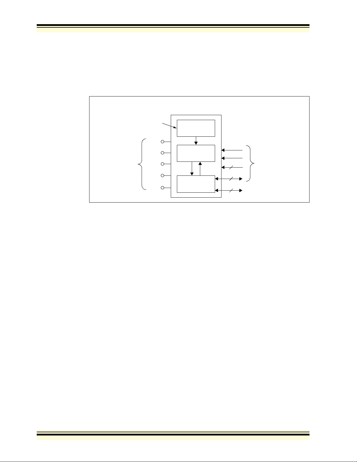
The Humidity Sensor PICtail™ Demo Board contains the circuitry represented in
Figure 1-1. The ambient relative humidity changes the capacitance of the humidity
sensor (HS1101LF from Humirel). This sensor is connected to a MCP6291 op amp and
a resistor to form an inverting (Miller) integrator. The PIC16F690 microcontroller sends
a square wave to the input of the integrator, which the integrator converts to a triangle
wave at its output. The firmware controls the magnitude of the triangle wave and
measures the integration time. The microcontroller measures the time it takes for the
triangle wave to rise and fall. These times are converted to a capacitance value.
A 14-pin header is provided for connecting to the PICkit™ 1 Flash Starter Kit, which
acts like a docking station. It includes a two-wire serial bus that transfers the data, and
two more wires for board power (+5V and GND inputs). This interface also supports
programming of the on-board PIC16F690.
© 2005 Microchip Technology Inc. DS51594A-page 5
Page 10
Humidity Sensor PICtail™ Demo Board User’s Guide
The +5V single supply voltage from the PICkit™ 1 Flash Starter Kit board is bypassed
with two bulk 1 μF capacitors near the header, and two local 0.1 μF capacitors (one for
each Integrated Circuit (IC)).
A 6-pin header for ICSP™ (In-Circuit Serial Programming™) is available as an alternate
interface for programming the on-board PIC16F690. This allows the user to modify the
program that comes with the Humidity Sensor PICtail™ Demo Board (with the MPLAB
ICD 2 or PICkit™ 2 microcontroller programmer).
Humidity Sensor
PICtail™ Demo Board
Ambient
Humidity
Humidity
Sensor
®
Tes t P oin ts
+5V
GND
Vsen
Vcm
Vint
Op Amp
MCP6291
N.C.
Microcontroller
PIC16F690
+5V
GND
10
2
6
to
PICkit™ 1 Flash
Starter Kit
ICSP™
FIGURE 1-1: Humidity Sensor PICtail™ Demo Board Block Diagram.
The test points make it easier to test key points in the circuit using common lab
equipment. The test points are:
• GND – Is connected to ground plane, and is for any lab equipment
• +5V – Positive supply voltage (at board edge); it provides a means to power this
board with a laboratory power supply (when not connected to the PICkit™ 1 Flash
Starter Kit)
•V
INT – Integrator’s input (a square wave during measurements)
CM – Op amp’s common mode voltage (at its inverting input)
•V
•V
SEN – Integrator’s output of the integrator (a triangle wave during
measurements)
More details on the circuit and on its design can be found in Appendix A. “Schematic
and Layouts” and AN1016, “Detecting Small Capacitive Sensors Using the MCP6291
and PIC16F690 Devices” (DS01016).
DS51594A-page 6 © 2005 Microchip Technology Inc.
Page 11

1.4 ASSOCIATED TOOLS
Figure 1-2 shows the block diagram of the hardware and software tools that the
Humidity Sensor PICtail™ Demo Board is designed to work with. More information on
these tools can be found in the “Recommended Reading” section.
Product Overview
Hardware Software
PC
USB
PICkit™ 1
Flash Starter Kit
14
Humidity Sensor
PICtail™ Demo Board
6
ICSP™
Capacitance.exe
PC Program
PICkit™ 1
Firmware
00084R1.hex
Firmware
FIGURE 1-2: Measurement Set-up Block Diagram.
1.4.1 Humidity Sensor PICtail™ Demo Board
This board is described in Section 1.3 “Humidity Sensor PICtail™ Demo Board”.
1.4.2 Firmware for the Humidity Sensor PICtail™ Demo Board
00084R1.hex is the firmware file that supports the Humidity Sensor PICtail™ Demo
Board application. It implements the measurement routines and the data
communications with the PICkit™ 1 Flash Starter Kit.
1.4.3 ICSP™ Header
The ICSP header provides a means to program the PIC16F690. It is intended for
connection to devices that program the on board PIC16F690, such as the MPLAB
®
ICD 2 (DV164005) and the PICkit™ 2 Microcontroller Programmer (DV164120).
1.4.4 PICkit™ 1 Flash Starter Kit
The PICkit 1 Flash Starter Kit (DV164101) programs PICmicro® microcontrollers. It is
used to program the PIC16F690, and provides a communications link with the PC. The
PICkit™ 1 Flash Starter Kit’s PIC16C745 has a USB port that communicates with the
Humidity Sensor PC Program. It also connects to the Humidity Sensor PICtail™ Demo
Board (the on-board PIC16F690) via a header (see Figure 2-1).
This board provides a single +5V supply voltage for the daughter board. It can drive up
to 5 μF on the supply; a larger capacitance may interfere with program timing.
1.4.5 PICkit™ 1 Firmware
This software resides on the PICkit™ 1 Flash Starter Kit’s PIC16C745 microcontroller.
Use version 2.0.2 or later.
© 2005 Microchip Technology Inc. DS51594A-page 7
Page 12

Humidity Sensor PICtail™ Demo Board User’s Guide
1.4.6 PC Platform
The Personal Computer (PC) shown in Figure 1-2 needs to run on Windows®98 SE or
later. It provides a convenient interface for the user, communicates with the other
boards and provides power through the USB connection.
1.4.7 Humidity Sensor PC Program
The capacitance.exe PC Program communicates with the PIC16F690 MCU on the
Humidity Sensor PICtail™ Demo Board through the USB port on the PICkit™ 1 Flash
Starter Kit. It also imports data through the same connections and displays them.
The user inputs the board configuration, and can select to view either capacitance or
relative humidity (assuming the HS1101LF sensor is plugged in).
1.5 ASSEMBLY CODE MODULES
The following assembly code modules (for the PIC16F690) make up the Humidity
Sensor project:
• main.inc - contains I/O port and global defines used throughout the project
• main.asm - contains the main executive routine including configuration bit
assignments
• initialize_f690.asm - initializes the PIC16F690 to known initial values
• capacitance.asm - reads capacitance using a dual slope integration technique
• humidity.inc - contains PwLI table segment values
• humidity.asm - contains PwLI routine to convert capacitance to %RH humidity
• ssc.asm - contains Synchronous Serial Communications (SSC), which is a
synchronous serial communications protocol between a target PICmicro
controller (MCU) and the PICkit™ 1 Flash Starter Kit or PICkit™ 2 Starter Kit
• 16f690.lkr - linker script for Humidity Sensor project
These files can be downloaded from the Microchip web site (www.microchip.com) and
are contained in the “00084R1.zip” file.
®
micro-
DS51594A-page 8 © 2005 Microchip Technology Inc.
Page 13

Chapter 2. Setup and Installation
2.1 INTRODUCTION
This chapter shows how to set up the Humidity Sensor PICtail™ Demo Board. Items
discussed in this chapter include:
• Required Tools
• Connecting the Humidity Sensor PICtail™ Demo Board
• Set-up Verification
2.2 REQUIRED TOOLS
The PICkit™ 1 Flash Starter Kit User’s Guide explains how to set up the PC and the
PICkit™ 1 Flash Starter Kit. Use firmware version 2.0.2 or later.
The PICkit™ 1 Flash Starter Kit CD-ROM (DS40049) contains many of the necessary
files.
The capacitance.exe PC program comes with the Humidity Sensor PICtail™ Demo
Board CD-ROM (Version v1.07.01 or later).
HUMIDITY SENSOR PICTAIL™
DEMO BOARD USER’S GUIDE
2.3 SETTING UP THE HUMIDITY SENSOR PICTAIL™ DEMO BOARD
This section discusses the primary method for setting up the Humidity Sensor PICtail™
Demo Board. An exploded view of how the different boards connect is shown in
Figure 2-1.
ICSP™ Header
USB Cable
Expansion
Header (J3)
To PC
PIC16C745 Firmware
Version 2.0.2 or later
FIGURE 2-1: Board Connections for PICkit™ 1 Flash Starter Kit.
Humidity Sensor
PICtail™ Demo Board
Remove PICmicro® MCU
Evaluation Socket
PICkit™ 1 Flash Starter Kit
© 2005 Microchip Technology Inc. DS51594A-page 9
Page 14

Humidity Sensor PICtail™ Demo Board User’s Guide
2.3.1 PICkit™ 1 Flash Starter Kit
1. Remove any PICmicro microcontroller that may be in the Evaluation Socket.
2. Connect the USB cable to the PC and to the PICkit™ 1 Flash Starter Kit board.
The status LEDs (green POWER and yellow BUSY in the LED array) should light
up.
It is easiest to use this board when it lays directly on a bench top.
2.3.2 Humidity Sensor PICtail™ Demo Board
1. Setup Board (first time only); connect shunt to jumper JP1 at the 0.1 pF / position
(0.1 pF / count).
2. Plug this board into the PICkit 1 Flash Starter Kit’s expansion header J3 (as
shown in Figure 2-1) without covering the LED array. There should be no change
in the status LEDs on the PICkit™ 1 Flash Starter Kit board after it is plugged in.
The PIC16F690 comes with the 00084R1.hex file already programmed.
2.3.3 Humidity Sensor PC Program
1. Run the installer program, AN1016 install.exe (which places the executable
file capacitance.exe in the desired directory).
2. Run the capacitance.exe PC Program to start the Graphical User Interface
(GUI).
2.3.4 Set-up Verification
1. Check Basic Functionality.
a) Place one of the capacitors that came in the shipping box (nominal values of
10 pF, 180 pF, 1.0 nF and 100 nF) into the Csen socket.
b) Follow the steps 1.a. through 1.g. in Section 3.3 “Using the Humidity
Sensor PC Program”.
c) The reading should be within ±5% (for 10 pF, 180 pF, and 1.0 nF capacitors),
or ±10% (for the 100 nF capacitor only), of the nominal value.
2. Check HS1101LF Sensor.
a) Place the HS1101LF sensor into the Csen socket.
b) Follow the steps 2.a. through 2.f. in Section 3.3 “Using the Humidity
Sensor PC Program”.
c) The reading should be similar to that of a calibrated relative humidity sensor
placed nearby.
DS51594A-page 10 © 2005 Microchip Technology Inc.
Page 15

2.4 CONNECTING TO ALTERNATE TOOLS
2.4.1 PICkit™ 2 Microcontroller Programmer
An exploded view of how the PICkit™ 2 microcontroller programmer connects to the
Humidity Sensor PICtail™ Demo Board is shown in Figure 2-2. This setup is an
alternative way to reprogram the PIC16F690 on the Humidity Sensor PICtail™ Demo
Board.
USB Cable
Setup and Installation
To PC
ICSP™ Header (P2)
PICkit™ 2 Microcontroller Programmer
Humidity Sensor
PICtail™ Demo Board
FIGURE 2-2: Board Connections for PICkit™ 2 Microcontroller Programmer.
2.4.2 MPLAB® ICD 2
An exploded view of how the MPLAB® ICD 2 connects to the Humidity Sensor
PICtail™ Demo Board is shown in Figure 2-3. This setup is an alternative way to
reprogram the PIC16F690 on the Humidity Sensor PICtail™ Demo Board.
USB Cable
To PC
MPLAB
®
ICD 2
Modular Connector Cable
Modular-to-6-Pin Header Adaptor
ICSP™ Header (P2)
Humidity Sensor
PICtail™ Demo Board
®
FIGURE 2-3: Board Connections for MPLAB
© 2005 Microchip Technology Inc. DS51594A-page 11
ICD 2.
Page 16

Humidity Sensor PICtail™ Demo Board User’s Guide
NOTES:
DS51594A-page 12 © 2005 Microchip Technology Inc.
Page 17

HUMIDITY SENSOR PICTAIL™
DEMO BOARD USER’S GUIDE
Chapter 3. Operation
3.1 INTRODUCTION
This demonstration board makes it easy to explore the operation of a humidity sensor
application. Items discussed in this chapter include:
• Configuring the Humidity Sensor PICtail™ Demo Board
• Using the Humidity Sensor PC Program
• Programming the PIC16F690
• Humidity Sensor Calibration
3.2 CONFIGURING THE HUMIDITY SENSOR PICTAIL™ DEMO BOARD
1. Setup the board as explained in Chapter 2. “Setup and Installation”.
2. Place a humidity sensor or capacitor in the C
a) Humirel’s HS1101LF capacitive humidity sensor.
b) A capacitor of known value.
3. Connect the shunt to jumpers JP1 – JP3 according to the measurement
resolution and capacitance values desired; see Table 3-1.
4. Allow sufficient time for the humidity sensor to respond to changes in the
environment (about 30 seconds for the HS1101LF).
SEN
socket.
TABLE 3-1: JUMPER SELECTION – MODIFIED CIRCUIT
Jumper
Selected
JP1 0.1 0.6 pF to 6.5 nF 6.65 M Use for HS1101LF sensor
JP2 1 6 pF to 65 nF 665 k
JP3 10 60pF to 650nF 66.5k
Measurement
Resolution
(pF / count)
C
SEN
Range
3.3 USING THE HUMIDITY SENSOR PC PROGRAM
The capacitance.exe PC Program Graphical User Interface (GUI) is displayed in
Figure 3-1. It is a simple program that helps the user to control the functionality of the
Humidity Sensor PICtail™ Demo Board and to view the results sent back from that
board.
Note: This program is intended as an evaluation tool; it does not check for all
possible errors. It is the user’s responsibility to make sure the GUI and
demo board are used under reasonable conditions.
R
(Ω)
INT
Comments
© 2005 Microchip Technology Inc. DS51594A-page 13
Page 18

Humidity Sensor PICtail™ Demo Board User’s Guide
1.c. 2.d.2.e.
1.e.1.f.
2.d.2.e.
4.a.
4.b.
1.d.
1.g.
3.b.
1.e.
2.d.
3.a.
2.c.
2.f.
3.c.
FIGURE 3-1: “Humidity Sensor PC Program” GUI.
The following steps will help familiarize the user with this GUI. The step numbers are
displayed in Figure 3-1.
1. Measure Capacitance (C
a) Put capacitor in C
SEN
).
SEN
’s socket on the board.
b) Select desired resolution on the board (set by shunt and JP1 – JP3).
c) Input the resolution.
d) Click on the READ CAPACITANCE button.
e) The green light turns on and the status window is updated.
f) Read the current capacitance value (which is updated about once a second).
g) Click on the STOP READING button.
2. Measure Humidity (RH).
a) Put the HS1101LF sensor in C
’s socket on the board.
SEN
b) Select the 0.1 pF / count resolution on the board (put shunt across JP1).
c) Click on the READ HUMIDITY button (a resolution of 0.1 pF / count is assumed
by the GUI).
d) The green lights turn on and the status window is updated.
e) Read the current capacitance value and relative humidity (which are updated
about once a second).
f) Click on the STOP READING button.
3. Check Program Status.
a) Read the status history in the status window.
b) Click the CLEAR STATUS WINDOW button to clear the status history.
c) Click the FIRMWARE VERSION button to see the version displayed in the status
window.
4. Quit the Program.
a) Click the FILE button, then the EXIT button that pops up. Or click on the
WINDOWS’ EXIT button.
DS51594A-page 14 © 2005 Microchip Technology Inc.
Page 19

3.4 HUMIDITY SENSOR CALIBRATION
If desired, the capacitive humidity sensor used on this board can be calibrated. Manufacturing tolerances, aging and changes in circuit operating conditions (i.e., supply
voltage and temperature) may cause errors larger than desired. Many reputable
companies provide humidity calibration equipment and/or services.
There are two common approaches to calibrating these sensors:
1. Put sensor in an atmosphere with well controlled RH.
2. Use another, more accurate sensor to measure the RH.
In both cases, there are two areas of concern. First, the RH can change rapidly across
time and position, making an accurate calibration difficult to do. Second, it takes time
for humidity sensors to settle to an accurate value. Some can take many minutes to
settle properly.
Operation
© 2005 Microchip Technology Inc. DS51594A-page 15
Page 20

Humidity Sensor PICtail™ Demo Board User’s Guide
NOTES:
DS51594A-page 16 © 2005 Microchip Technology Inc.
Page 21

4.1 INTRODUCTION
HUMIDITY SENSOR PICTAIL™
DEMO BOARD USER’S GUIDE
Chapter 4. Modified Circuit
The modifications described here will reduce the current going into the integrator (I
by a factor of 100 ×, so the measurement resolution increases by the same factor.
These modifications are intended for measuring small capacitances. See AN1016 for
more details on this modified circuit’s performance.
4.2 THE “REDUCED CURRENT” CIRCUIT
4.2.1 Modifications
Figure 4-1 shows the Humidity Sensor PICtail™ Demo Board top silk-screen.
Figure 4-1 also shows the locations of the resistors that need to be modified to
implement the “Reduced Current” circuit discussed in application note AN1016:
1. Remove (de-solder) the 1Ω resistor, RA1, already on the board.
2. Refer to Appendix B. “Bill Of Materials (BOM)”, Section B.3 for the BOM for
the three resistors (provided by the user) that need to be soldered onto the board.
-RA1=1MΩ
- RA2=RA3=20kΩ
3. Solder RA1, RA2 and RA3 onto the board.
INT
)
resistors to
to modify
FIGURE 4-1: Resistor Modifications.
© 2005 Microchip Technology Inc. DS51594A-page 17
Page 22

Humidity Sensor PICtail™ Demo Board User’s Guide
4.2.2 Modified Configuration
Configure the Humidity Sensor PICtail™ Demo Board as follows:
1. Start with the configuration in Section 3.2.
2. Connect the shunt to jumpers JP1 – JP3 according to the modified measurement
resolutions and capacitance values desired; see Table 4-1.
TABLE 4-1: JUMPER SELECTION – MODIFIED CIRCUIT
Jumper
Selected
JP1 0.001 0.6 pF to 65 pF 6.65 M
JP2 0.01 6 pF to 650 pF 665 k
JP3 0.1 60 pF to 6.5 nF 66.5 k
4.2.3 Interpreting the Output from the Humidity Sensor PC Program
The capacitance.exe PC program displays measured capacitance values assuming
the Humidity Sensor PICtail™ Demo Board has not been modified. To correct the displayed values, move the displayed decimal point to the left two places (e.g., 321.0 pF is
actually 3.210 pF).
Measurement Resolution
(pF / count)
C
SEN
Range
R
INT
(Ω)
Note: The decimal point must be moved two places to the left by the user for the
modified circuit.
The RH numbers make no sense for measurements produced by the modified board;
they are based on another circuit configuration (see Section 3.2).
DS51594A-page 18 © 2005 Microchip Technology Inc.
Page 23

Appendix A. Schematic and Layouts
A.1 INTRODUCTION
This appendix contains the schematics and layouts for the Humidity Sensor PICtail™
Demo Board.
A.2 HIGHLIGHTS
The Humidity Sensor PICtail™ Demo Board is constructed using a two-layer Printed
Circuit Board (PCB). The top layer is for components and traces. The bottom layer is
the ground plane.
Information on this board includes:
• Board Schematic
• Board – Top Silk-screen
• Board – Top Metal Layer
• Board – Bottom Metal Layer
HUMIDITY SENSOR PICTAIL™
DEMO BOARD USER’S GUIDE
A.3 DEMONSTRATION BOARD DESCRIPTION
A schematic is shown in Figure A-1 and Figure A-2. Csen is the humidity sensor or
capacitor. Op amp, U2, and the components, Csen and R
form an inverting (Miller) integrator. The jumpers, JP1 – JP3, select the R
choice (6.65 MΩ, 665 kΩ or 66.5 kΩ), which sets the measurement resolution
(0.1 pF / count, 1 pF / count or 10 pF / count). The microcontroller, U1, sends a square
wave at its pin 14 to the input of the integrator. The integrator converts it to a triangle
wave, which is seen at the microcontroller’s pin 15. There is a comparator internal to
U1 which compares the voltage at pin 15 to one of two reference levels; V
V
or VRH= 0.500 VDD. The microcontroller changes the logic value output at pin 14
DD
each time the triangle wave exceeds one of these two limits.
The microcontroller (U1) measures the time between changes in logic values at pin 14
(“integration times”), and calculates a capacitance value for Csen. This capacitance
value (C
sensor. C
them to the capacitance.exe PC program on the PC via the USB cable.
Note: Converting Csen to RH for other humidity sensors must be done either
RA1 – RA3 are used for the “Op Amp Integrator with Reduced Current” described in
AN1016 and Chapter 4. “Modified Circuit”. Rcm1, Rcm2 and Ccm provide a
mid-supply reference voltage for the op amp, U2.
) is converted to Relative Humidity (RH) for Humirel’s HS1101LF humidity
SEN
and RH are then sent to the PICkit™ 1 Flash Starter Kit, which sends
SEN
manually or by modifying the PIC16F690 firmware (i.e., the linear
interpolation table).
(Rint1, Rint2 or Rint3),
INT
value of
INT
RL
= 0.125
© 2005 Microchip Technology Inc. DS51594A-page 19
Page 24

Humidity Sensor PICtail™ Demo Board User’s Guide
The test points, TP3 – TP5, have 10 kΩ placed in series to isolate the circuit from
external measurement equipment. This will help prevent over-voltage events, and will
help the op amp, U2, operate in a stable condition.
a) This is a two-layer board. It has a solid ground plane on the bottom layer to
minimize EMC issues, and routes the traces in the top layer. The complete
schematic is in Figure A-1 and Figure A-2, the board layer plots in Figure A-3,
Figure A-4 and Figure A-5. The Bill of Materials (BOM) is in Appendix
B. “Bill Of Materials (BOM)”. The Gerber files for this board are available on
the Microchip web site (www.microchip.com) and are contained in the zip file
00084R1.zip.
A.4 THE “REDUCED CURRENT” MODIFICATION
Figure A-1 shows the Humidity Sensor PICtail™ Demo Board as it comes from
Microchip. This board can be modified by the user to implement the “Reduced Current”
circuit discussed in application note AN1016 and Chapter 4. “Modified Circuit”.
A.5 ADDITIONAL COMMENTS
The demonstration board includes test points for convenience on the bench. The “+5V”
and “GND” test points (TP1 and TP2) connect to the board’s supply voltages.
Note: Do NOT connect a power supply to the “+5V” and “GND” test points, unless
the board is NOT connected to the PICkit™ 1 Flash Starter Kit (i.e., it
stands alone).
The “V
square wave into the integrator. The “V
the op amp’s common mode input voltage. The “V
tion to the op amps output to allow the user to monitor the triangle wave at the integrator’s output.
The PICkit™ 1 Flash Starter Kit provides a +5V single supply voltage. It can drive up to
5 μF on the supply; a larger capacitive load causes current loading and timing issues.
This demonstration board also uses the +5V single supply voltage. It has two 1 μF bulk
bypass capacitors and two 0.1 μF local bypass capacitors.
High frequency design practices are used to minimize digital interference:
• Solid ground plane
• Surface mount devices for the analog circuitry
• Separate digital and analog lines and sections
INT” test point (TP3) connects to U1’s pin 14 to allow the user to monitor the
CM” test point (TP4) allows the user to measure
SEN” test point (TP5) allows connec-
DS51594A-page 20 © 2005 Microchip Technology Inc.
Page 25

C
0.1 μF
Schematic and Layouts
+5V
1
U1
PIC16F690/P
20
SS
V
19
18
17
RA0
RA1
16
15
14
13
RC1
RC2
12
11
RA3
1
VDD
2
RA5/T1CKI/OSC1/CLKIN
3
RA4/AN3/T1G/OSC2/CLKOUT
4
RA3/MCLR/V
5
RC5/CCP1/P1A
6
RC4/C2OUT/P1B
7
RC3/AN7/P1C
8
RC6/AN8/SS
9
RC7/AN9/SDO
10
RB7/TX/CK
PP
RA0/AN0/C1IN+/ICSPDAT/ULPWU
RA1/AN1/C12IN-/V
REF/ICSPCLK
RA2/AN2/T0CLKI/INT/C1OUT
RC0/AN4/C2IN+
RC1/AN5/C12IN-
RC2/AN6/P1D
RB4/AN10/SDI/SDA
RB5/AN11/RX/DT
RB6/SCK/SCL
RC1
TP5
V
SEN
R
10 kΩ
2
HS1101LF
C
2
0.1 μF
MCP6291
1
Csen
Humidity
+5VA
U
2
TP4
CM
V
R
INT1
R
3
10kΩ
21
6.65 MΩ
R
INT2
66.5 kΩ
R
INT3
66.5 kΩ
JP1
0.1pF/
JP2
1.0pF/
JP3
10pF/
+5VA
R
A2
OPEN
R
A3
OPEN
R
0Ω
TP3
V
INT
R
4
10 kΩ
A1
RC2
+5VA
5
4
3
+
2
R
CM1
20 kΩ
R
CM2
20 kΩ
C
CM
0.1μF
NOTE: All Resistors are 1%
FIGURE A-1: Board – Schematic.
© 2005 Microchip Technology Inc. DS51594A-page 21
Page 26

Humidity Sensor PICtail™ Demo Board User’s Guide
TP2
TP1
+5V
RA3
RA0
RA1
RA3
RA0
RA1
P1
RA5
1
RA4
2
3
RA3
4
RC5
5
RC4
6
RC3
7
RA0
8
RA1
9
RA2
10
RC0
11
RC1
12
RC2
13
+5V
14
GND
P2
ICSP
1
PP
V
2
VDD
3
GND
4
ICSPDAT
5
ICSPCLK
6
AUX
Expansion Header J3
PICkit™ 1 Flash Starter Kit
+5VA
C
1 μF
GND
R
100Ω
3
+5V
5
C
4
1 μF
FIGURE A-2: Board – Schematic. (Continued)
NOTE: All Resistors are 1%
DS51594A-page 22 © 2005 Microchip Technology Inc.
Page 27

Schematic and Layouts
FIGURE A-3: Board – Top Silk-Screen.
FIGURE A-4: Board – Top Metal Layer.
© 2005 Microchip Technology Inc. DS51594A-page 23
Page 28

Humidity Sensor PICtail™ Demo Board User’s Guide
FIGURE A-5: Board – Bottom Metal Layer.
DS51594A-page 24 © 2005 Microchip Technology Inc.
Page 29

HUMIDITY SENSOR PICTAIL™
DEMO BOARD USER’S GUIDE
Appendix B. Bill Of Materials (BOM)
B.1 HUMIDITY SENSOR PICTAIL™ DEMO BOARD BOM
Table B-1 shows the BOM for the Humidity Sensor PICtail™ Demo Board as it comes
from Microchip.
TABLE B-1: BILL OF MATERIALS
Qty Reference Description Manufacturer Part Number
1C
SEN Ceramic Capacitor, Monolithic, 180 pF, 50V, 5%, C0G,
Radial 0.2"
3C1, C2, C
2 C3, C4 Ceramic Capacitor, 1.0 μF, 16V, 10%, X7R, 0805 SMD Kemet C0805C105K4RACTU
1 P1 Header, 1 × 14, 0.100" Pitch, Vertical, Gold Molex/Waldom
1 P2 Header, 1 × 6, 0.100” Pitch, Right Angle, Gold Molex/Waldom
1 JP1 – JP3 Header, 2 × 3, 0.100” Pitch, Vertical, Gold Molex/Waldom
1 (for JP1 – JP3) Shunt, 1 × 2, With Handle, Gold AMP/Tyco
1 RA1 Chip Resistor, 1.00 Ω, 1/8W, 5%, 0805 SMD (Note 1) Yageo America RC0805FR-071RL
0 RA2, RA3 (not used; left open) (Note 1) ——
1 R5 Chip Resistor, 100 Ω, 1/8W, 1%, 0805 SMD Yageo America RC0805FR-07100RL
3 R2 – R4 Chip Resistor, 10.0 kΩ, 1/8W, 1%, 0805 SMD Yageo America RC0805FR-0710KL
2R
1R
1R
1R
5 TP1 – TP5 PCB Test Point, Compact, SMT Keystone
1 U1 PIC16F690, PICmicro
1 U2 MCP6291, Single Op Amp, 10 MHz, V
2(for C
1 (for U1) IC Socket, 20-pin DIP, Gold Plated, 0.400" Mill-Max
1 (for PCB mounting) Stand-off, Hex, 1.000”, 4 × 40 Thread, Nylon,
1 (for PCB mounting) Machine Screw, Phillips, 4 × 40 Thread, 1/4 in long, Nylon Digi-Key H542-ND
1 PCB Bare Printed Circuit Board — —
Note 1: These resistors are intended for the “Reduced Current” circuit modifications detailed in Table B-3.
CM Ceramic Capacitor, 100 nF, 50V, 10%, X7R, 0805 SMD Kemet C0805C104K5RACTU
CM1, RCM2 Chip Resistor, 20.0 kΩ, 1/8W, 1%, 0805 SMD Yageo America RC0805FR-0720KL
INT3 Chip Resistor, 66.5 kΩ, 1/8W, 1%, 0805 SMD Yageo America RC0805FR-0766K5L
INT2 Chip Resistor, 665 kΩ, 1/8W, 1%, 0805 SMD Yageo America RC0805FR-07665KL
INT1 Chip Resistor, 6.65 MΩ, 1/8W, 1%, 0805 SMD Yageo America RC0805FR-076M65L
®
PDIP-20
SOT-23-5
SEN) Pin Recepticle, 0.015” to 0.025” dia., 0.060” hole dia. Mill-Max
0.285” max. O.D
Microcontroller, 20-pin, 20 MHz,
≤ ±3 mV,
OS
EPCOS Inc. B37979N5181J051
Electronics
Electronics
Electronics
Electronics
Electronics
Microchip PIC16F690-I/P
Microchip MCP6291-E/OT
®
®
Keystone
Electronics
22-28-4143
22-28-8062
10-89-1061
881545-2
5016
0669-0-15-15-30-27-10-0
110-13-420-41-001000
1902C
© 2005 Microchip Technology Inc. DS51594A-page 25
Page 30

Humidity Sensor PICtail™ Demo Board User’s Guide
B.2 BOM FOR HUMIDITY SENSOR AND OTHER CAPACITORS IN BOX
Table B-2 lists capacitors included separately in the Humidity Sensor PICtail™ Demo
Board’s shipping box. These capacitors or the HS1101LF sensor will fit in the Csen pin
recepticles. The capacitors provide a means for quickly evaluating circuit operation.
TABLE B-2: BILL OF MATERIALS FOR HUMIDITY SENSOR AND OTHER CAPACITORS
Qty Reference Description Manufacturer Part Number
1CSEN Relative Humidity Sensor, Capacitive Cell, 180 pF, 5V,
1C
SEN Ceramic Capacitor, Monolithic, 100 pF, 50V, 5%, C0G, Radial 0.2" EPCOS Inc. B37979N5101J000
1C
SEN Ceramic Capacitor, Monolithic, 1.0 nF, 50V, 5%, C0G, Radial 0.2" EPCOS Inc. B37979G5102J000
SEN Ceramic Capacitor, Monolithic, 100 nF, 50V, 10%, X7R, Radial 0.2" EPCOS Inc. B37987F5104K000
1C
1% to 99% RH, -40°C to +140°C
B.3 BOM FOR “REDUCED CURRENT” MODIFICATIONS
Table B-3 shows the components for the “Reduced Current” circuit modifications
discussed in application note AN1016 and Chapter 4. “Modified Circuit”.
TABLE B-3: BILL OF MATERIALS FOR “REDUCED CURRENT” MODIFICATIONS
Humirel HS1101LF
Qty Reference Description Manufacturer Part Number
2 RA2, RA3 Chip Resistor, 20.0 kΩ, 1/8W, 1%, 0805 SMD Yageo America RC0805FR-0720KL
1 RA1 Chip Resistor, 1.00 MΩ, 1/8W, 1%, 0805 SMD Yageo America RC0805FR-071ML
DS51594A-page 26 © 2005 Microchip Technology Inc.
Page 31

NOTES:
Bill Of Materials (BOM)
© 2005 Microchip Technology Inc. DS51594A-page 27
Page 32

WORLDWIDE SALES AND SERVICE
AMERICAS
Corporate Office
2355 West Chandler Blvd.
Chandler, AZ 85224-6199
Tel: 480-792-7200
Fax: 480-792-7277
Technical Support:
http://support.microchip.com
Web Address:
www.microchip.com
Atlanta
Alpharetta, GA
Tel: 770-640-0034
Fax: 770-640-0307
Boston
Westborough, MA
Tel: 774-760-0087
Fax: 774-760-0088
Chicago
Itasca, IL
Tel: 630-285-0071
Fax: 630-285-0075
Dallas
Addison, TX
Tel: 972-818-7423
Fax: 972-818-2924
Detroit
Farmington Hills, MI
Tel: 248-538-2250
Fax: 248-538-2260
Kokomo
Kokomo, IN
Tel: 765-864-8360
Fax: 765-864-8387
Los Angeles
Mission Viejo, CA
Tel: 949-462-9523
Fax: 949-462-9608
San Jose
Mountain View, CA
Tel: 650-215-1444
Fax: 650-961-0286
Toronto
Mississauga, Ontario,
Canada
Tel: 905-673-0699
Fax: 905-673-6509
ASIA/PACIFIC
Australia - Sydney
Tel: 61-2-9868-6733
Fax: 61-2-9868-6755
China - Beijing
Tel: 86-10-8528-2100
Fax: 86-10-8528-2104
China - Chengdu
Tel: 86-28-8676-6200
Fax: 86-28-8676-6599
China - Fuzhou
Tel: 86-591-8750-3506
Fax: 86-591-8750-3521
China - Hong Kong SAR
Tel: 852-2401-1200
Fax: 852-2401-3431
China - Qingdao
Tel: 86-532-8502-7355
Fax: 86-532-8502-7205
China - Shanghai
Tel: 86-21-5407-5533
Fax: 86-21-5407-5066
China - Shenyang
Tel: 86-24-2334-2829
Fax: 86-24-2334-2393
China - Shenzhen
Tel: 86-755-8203-2660
Fax: 86-755-8203-1760
China - Shunde
Tel: 86-757-2839-5507
Fax: 86-757-2839-5571
China - Wuhan
Tel: 86-27-5980-5300
Fax: 86-27-5980-5118
China - Xian
Tel: 86-29-8833-7250
Fax: 86-29-8833-7256
ASIA/PACIFIC
India - Bangalore
Tel: 91-80-2229-0061
Fax: 91-80-2229-0062
India - New Delhi
Tel: 91-11-5160-8631
Fax: 91-11-5160-8632
India - Pune
Tel: 91-20-2566-1512
Fax: 91-20-2566-1513
Japan - Yokohama
Tel: 81-45-471- 6166
Fax: 81-45-471-6122
Korea - Gumi
Tel: 82-54-473-4301
Fax: 82-54-473-4302
Korea - Seoul
Tel: 82-2-554-7200
Fax: 82-2-558-5932 or
82-2-558-5934
Malaysia - Penang
Tel: 60-4-646-8870
Fax: 60-4-646-5086
Philippines - Manila
Tel: 63-2-634-9065
Fax: 63-2-634-9069
Singapore
Tel: 65-6334-8870
Fax: 65-6334-8850
Taiwan - Hsin Chu
Tel: 886-3-572-9526
Fax: 886-3-572-6459
Taiwan - Kaohsiung
Tel: 886-7-536-4818
Fax: 886-7-536-4803
Taiwan - Taipei
Tel: 886-2-2500-6610
Fax: 886-2-2508-0102
Thailand - Bangkok
Tel: 66-2-694-1351
Fax: 66-2-694-1350
EUROPE
Austria - Wels
Tel: 43-7242-2244-399
Fax: 43-7242-2244-393
Denmark - Copenhagen
Tel: 45-4450-2828
Fax: 45-4485-2829
France - Paris
Tel: 33-1-69-53-63-20
Fax: 33-1-69-30-90-79
Germany - Munich
Tel: 49-89-627-144-0
Fax: 49-89-627-144-44
Italy - Milan
Tel: 39-0331-742611
Fax: 39-0331-466781
Netherlands - Drunen
Tel: 31-416-690399
Fax: 31-416-690340
Spain - Madrid
Tel: 34-91-708-08-90
Fax: 34-91-708-08-91
UK - Wokingham
Tel: 44-118-921-5869
Fax: 44-118-921-5820
10/31/05
DS51594A-page 28 © 2005 Microchip Technology Inc.
 Loading...