

Page 1

F1 LV Evaluation Platform
Motor Control Add-Ons
User’s Guide
2012 Microchip Technology Inc. DS41629A
Page 2

Note the following details of the code protection feature on Microchip devices:
YSTEM
CERTIFIED BY DNV
== ISO/TS 16949 ==
• Microchip products meet the specification contained in their particular Microchip Data Sheet.
• Microchip believes that its family of products is one of the most secure families of its kind on the market today, when used in the
intended manner and under normal conditions.
• There are dishonest and possibly illegal methods used to breach the code protection feature. All of these methods, to our
knowledge, require using the Microchip products in a manner outside the operating specifications contained in Microchip’s Data
Sheets. Most likely, the person doing so is engaged in theft of intellectual property.
• Microchip is willing to work with the customer who is concerned about the integrity of their code.
• Neither Microchip nor any other semiconductor manufacturer can guarantee the security of their code. Code protection does not
mean that we are guaranteeing the product as “unbreakable.”
Code protection is constantly evolving. We at Microchip are committed to continuously improving the code protection features of our
products. Attempts to break Microchip’s code protection feature may be a violation of the Digital Millennium Copyright Act. If such acts
allow unauthorized access to your software or other copyrighted work, you may have a right to sue for relief under that Act.
Information contained in this publication regarding device
applications and the like is provided only for your convenience
and may be superseded by updates. It is your responsibility to
ensure that your application meets with your specifications.
MICROCHIP MAKES NO REPRESENTATIONS OR
WARRANTIES OF ANY KIND WHETHER EXPRESS OR
IMPLIED, WRITTEN OR ORAL, STATUTORY OR
OTHERWISE, RELATED TO THE INFORMATION,
INCLUDING BUT NOT LIMITED TO ITS CONDITION,
QUALITY, PERFORMANCE, MERCHANTABILITY OR
FITNESS FOR PURPOSE. Microchip disclaims all liability
arising from this information and its use. Use of Microchip
devices in life support and/or safety applications is entirely at
the buyer’s risk, and the buyer agrees to defend, indemnify and
hold harmless Microchip from any and all damages, claims,
suits, or expenses resulting from such use. No licenses are
conveyed, implicitly or otherwise, under any Microchip
intellectual property rights.
Trademarks
The Microchip name and logo, the Microchip logo, dsPIC,
K
EELOQ, KEELOQ logo, MPLAB, PIC, PICmicro, PICSTART,
32
PIC
logo, rfPIC and UNI/O are registered trademarks of
Microchip Technology Incorporated in the U.S.A. and other
countries.
FilterLab, Hampshire, HI-TECH C, Linear Active Thermistor,
MXDEV, MXLAB, SEEVAL and The Embedded Control
Solutions Company are registered trademarks of Microchip
Technology Incorporated in the U.S.A.
Analog-for-the-Digital Age, Application Maestro, chipKIT,
chipKIT logo, CodeGuard, dsPICDEM, dsPICDEM.net,
dsPICworks, dsSPEAK, ECAN, ECONOMONITOR,
FanSense, HI-TIDE, In-Circuit Serial Programming, ICSP,
Mindi, MiWi, MPASM, MPLAB Certified logo, MPLIB,
MPLINK, mTouch, Omniscient Code Generation, PICC,
PICC-18, PICDEM, PICDEM.net, PICkit, PICtail, REAL ICE,
rfLAB, Select Mode, Total Endurance, TSHARC,
UniWinDriver, WiperLock and ZENA are trademarks of
Microchip Technology Incorporated in the U.S.A. and other
countries.
SQTP is a service mark of Microchip Technology Incorporated
in the U.S.A.
All other trademarks mentioned herein are property of their
respective companies.
© 2012, Microchip Technology Incorporated, Printed in the
U.S.A., All Rights Reserved.
Printed on recycled paper.
QUALITY MANAGEMENT S
DS41629A-page 2 2012 Microchip Technology Inc.
ISBN: 9781620761236
Microchip received ISO/TS-16949:2009 certification for its worldwide
headquarters, design and wafer fabrication facilities in Chandler and
Tempe, Arizona; Gresham, Oregon and design centers in California
and India. The Company’s quality system processes and procedures
are for its PIC
devices, Serial EEPROMs, microperipherals, nonvolatile memory and
analog products. In addition, Microchip’s quality system for the design
and manufacture of development systems is ISO 9001:2000 certified.
®
MCUs and dsPIC® DSCs, KEELOQ
®
code hopping
Page 3

F1 LV EVALUATION PLATFORM
MOTOR CONTROL ADD-ONS
Table of Contents
Chapter 1. F1 LV Evaluation Platform Overview
1.1 Introduction ............................................................................................. 13
1.2 Hardware Overview ................................................................................ 13
1.2.1 Evaluation Platforms .............................................................................. 13
1.2.2 Add-on Boards ....................................................................................... 13
1.2.3 USB Interface ........................................................................................ 14
1.2.4 Add-on Board Power ............................................................................. 14
1.2.5 Add-on Board Memory .......................................................................... 14
1.3 PC Software Overview ........................................................................... 14
1.4 Using the F1LVDemo Control Software ................................................. 17
1.4.1 Software Updates .................................................................................. 17
1.4.2 Serial Link .............................................................................................. 17
1.4.3 Connecting the F1 LV Evaluation Platform to the Add-on Board .......... 17
1.4.4 Connecting the F1 LV Evaluation Platform to the PC ............................ 17
1.4.5 Open Versus Closed Loop .................................................................... 18
1.4.6 Changing Motor Parameters ................................................................. 18
1.4.7 Saving and Restoring Motor Parameters .............................................. 18
1.4.8 Hints for Optimum Performance ............................................................ 19
1.4.9 Header File Versus GUI Motor Parameters ........................................... 19
Chapter 2. The BLDC Add-on Board
2.1 Overview ................................................................................................. 21
2.1.1 Features ................................................................................................ 21
2.1.2 What’s Included ..................................................................................... 21
2.1.3 Reference Documents ........................................................................... 22
2.2 Board Setup ............................................................................................ 22
2.3 Hardware ................................................................................................ 22
2.3.1 General Architecture .............................................................................. 22
2.3.2 Attaching the Motor ............................................................................... 23
2.3.3 Power-Up ............................................................................................... 23
2.3.4 Power Stage .......................................................................................... 23
2.3.5 Protection .............................................................................................. 24
2.3.6 Speed Control ........................................................................................ 24
2.4 Demo Software ....................................................................................... 24
2.4.1 Introduction ............................................................................................ 24
2.4.2 The Motor Control GUI Application ........................................................ 24
2.4.3 BLDC Parameter Optimization .............................................................. 25
Chapter 3. The Brushed DC Add-on Board
3.1 Getting Started ....................................................................................... 29
3.1.1 Overview ................................................................................................ 29
3.1.2 Features ................................................................................................ 29
3.1.3 What’s Included ..................................................................................... 29
2012 Microchip Technology Inc. DS41629A-page 3
Page 4

F1 LV Evaluation Platform Motor Control Add-Ons
3.1.4 Reference Documents ...........................................................................30
3.2 Board Setup ............................................................................................ 30
3.3 Hardware ................................................................................................ 30
3.3.1 General Architecture ..............................................................................30
3.3.2 Attaching the Motor ................................................................................31
3.3.3 Power-Up ...............................................................................................31
3.3.4 Power Stage ..........................................................................................31
3.3.5 Protection ...............................................................................................32
3.3.6 UNI/O
3.3.7 Speed Control ........................................................................................32
3.4 Demo Software ....................................................................................... 32
3.4.1 Introduction ............................................................................................32
3.4.2 The Motor Control GUI Application ........................................................32
Chapter 4. The Bipolar Stepper Add-on Board
4.1 Getting Started ....................................................................................... 33
4.1.1 Overview ................................................................................................33
4.2 Features ................................................................................................. 33
4.2.1 What’s Included .....................................................................................33
4.2.2 Reference Documents ...........................................................................33
4.3 Getting Started ....................................................................................... 34
4.4 Hardware ................................................................................................ 34
4.4.1 General Architecture ..............................................................................34
4.4.2 Attaching the Motor ................................................................................35
4.4.3 Power-Up ...............................................................................................35
4.4.4 Power Stage ..........................................................................................35
4.4.5 Protection ...............................................................................................36
4.4.6 UNI/O
4.4.7 Speed Control ........................................................................................36
4.4.8 Current Control ......................................................................................36
4.5 Demo Software ....................................................................................... 37
4.5.1 Introduction ............................................................................................37
4.5.2 The Motor Control GUI Application ........................................................37
4.6 Optimizing Stepper Motor Parameters ................................................... 38
4.6.1 Stepper Motor Closed-Loop Drive Overview .........................................38
4.6.2 Optimizing DUTY_SCALE and SPEED_SCALING_CONST .................39
®
Memory Chip .............................................................................32
®
Memory Chip .............................................................................36
Chapter 5. The Unipolar Stepper Add-on Board
5.1 Getting Started ....................................................................................... 41
5.1.1 Overview ................................................................................................41
5.1.2 Features .................................................................................................41
5.1.3 What’s Included .....................................................................................41
5.1.4 Reference Documents ...........................................................................42
5.2 Getting Started ....................................................................................... 42
5.3 Hardware ................................................................................................ 42
5.3.1 General Architecture ..............................................................................42
5.3.2 Attaching the Motor ................................................................................43
5.3.3 Power-Up ...............................................................................................43
5.3.4 Power Stage ..........................................................................................43
5.3.5 Protection ...............................................................................................44
DS41629A-page 4 2012 Microchip Technology Inc.
Page 5

5.3.6 UNI/O® Memory Chip ............................................................................ 44
5.3.7 Speed Control ........................................................................................ 44
5.3.8 Current Control ...................................................................................... 44
5.4 Demo Software ....................................................................................... 45
5.4.1 Introduction ............................................................................................ 45
5.4.2 The Motor Control GUI Application ........................................................ 45
5.5 Optimizing Stepper Motor Parameters ................................................... 46
5.5.1 Stepper Motor Closed-Loop Drive Overview ......................................... 46
5.5.2 Optimizing DUTY_SCALE and SPEED_SCALING_CONST ................ 47
Appendix A. Board Layout and Schematics
A.1 Introduction ............................................................................................. 49
Appendix B. Conversion Factors
B.1 Conversion Factor Derivations ............................................................... 55
B.2 Start-up: Speed ...................................................................................... 55
B.3 Slow Step ............................................................................................... 55
B.4 Stepper Run and Stop Percentages ....................................................... 56
B.5 Degrees Per Step ................................................................................... 56
B.6 Stepper: Min and Max Duty Percent ....................................................... 56
B.7 Constants Derived From Stepper Parameters ....................................... 56
B.7.1 DUTY_SCALE Constant ........................................................................ 56
B.7.2 SPEED_SCALING_CONST Constant ................................................... 57
B.8 uStep Table ............................................................................................ 57
2012 Microchip Technology Inc. DS41629A-page 5
Page 6

F1 LV Evaluation Platform Motor Control Add-Ons
NOTES:
DS41629A-page 6 2012 Microchip Technology Inc.
Page 7

F1 LV EVALUATION PLATFORM
MOTOR CONTROL ADD-ONS
Preface
NOTICE TO CUSTOMERS
All documentation becomes dated, and this manual is no exception. Microchip tools and
documentation are constantly evolving to meet customer needs, so some actual dialogs
and/or tool descriptions may differ from those in this document. Please refer to our web site
(www.microchip.com) to obtain the latest documentation available.
Documents are identified with a “DS” number. This number is located on the bottom of each
page, in front of the page number. The numbering convention for the DS number is
“DSXXXXXA”, where “XXXXX” is the document number and “A” is the revision level of the
document.
For the most up-to-date information on development tools, see the MPLAB
Select the Help menu, and then Topics to open a list of available online help files.
INTRODUCTION
®
IDE online help.
This chapter contains general information that will be useful to know before using the
F1 LV Evaluation Platform Motor Control Add-ons User’s Guide. Items discussed in this
chapter include:
• Document Layout
• Conventions Used in this Guide
• Warranty Registration
• Recommended Reading
• The Microchip Web Site
• Development Systems Customer Change Notification Service
• Customer Support
• Document Revision History
DOCUMENT LAYOUT
This document describes how to use the F1 LV Evaluation Platform Motor Control
Add-ons User’s Guide as a development tool to emulate and debug firmware on a
target board. The manual layout is as follows:
• Chapter 1. “F1 LV Evaluation Platform Overview”
• Chapter 2. “The BLDC Add-on Board”
• Chapter 3. “The Brushed DC Add-on Board”
• Chapter 4. “The Bipolar Stepper Add-on Board”
• Chapter 5. “The Unipolar Stepper Add-on Board”
• Appendix A. “Board Layout and Schematics”
• Appendix B. “Conversion Factors”
2012 Microchip Technology Inc. DS41629A-page 7
Page 8
F1 LV Evaluation Platform Motor Control Add-Ons
CONVENTIONS USED IN THIS GUIDE
This manual uses the following documentation conventions:
DOCUMENTATION CONVENTIONS
Description Represents Examples
Arial font:
Italic characters Referenced books MPLAB
Emphasized text ...is the only compiler...
Initial caps A window the Output window
A dialog the Settings dialog
A menu selection select Enable Programmer
Quotes A field name in a window or
dialog
Underlined, italic text with
right angle bracket
Bold characters A dialog button Click OK
N‘Rnnnn A number in verilog format,
Text in angle brackets < > A key on the keyboard Press <Enter>, <F1>
Courier New font:
Plain Courier New Sample source code #define START
Italic Courier New A variable argument file.o, where file can be
Square brackets [ ] Optional arguments mcc18 [options] file
Curly brackets and pipe
character: { | }
Ellipses... Replaces repeated text var_name [,
A menu path File>Save
A tab Click the Power tab
where N is the total number of
digits, R is the radix and n is a
digit.
Filenames autoexec.bat
File paths c:\mcc18\h
Keywords _asm, _endasm, static
Command-line options -Opa+, -Opa-
Bit values 0, 1
Constants 0xFF, ‘A’
Choice of mutually exclusive
arguments; an OR selection
Represents code supplied by
user
“Save project before build”
4‘b0010, 2‘hF1
any valid filename
[options]
errorlevel {0|1}
var_name...]
void main (void)
{ ...
}
®
IDE User’s Guide
DS41629A-page 8 2012 Microchip Technology Inc.
Page 9

WARRANTY REGISTRATION
Please complete the enclosed Warranty Registration Card and mail it promptly.
Sending in the Warranty Registration Card entitles users to receive new product
updates. Interim software releases are available at the Microchip web site.
RECOMMENDED READING
This user’s guide describes how to use the F1 LV Evaluation Platform Motor Control
Add-ons User’s Guide. Other useful documents are listed below. The following Microchip documents are available and recommended as supplemental reference
resources.
Readme for F1 LV Evaluation Platform Motor Control Add-ons User’s Guide
For the latest information on using F1 LV Evaluation Platform Motor Control Add-ons
User’s Guide, read the “Readme for F1 LV Evaluation Platform Motor Con-
trol Add-ons User’s Guide.txt” file (an ASCII text file) in the Readmes subdirectory of the MPLAB IDE installation directory. The Readme file contains update
information and known issues that may not be included in this user’s guide.
Readme Files
For the latest information on using other tools, read the tool-specific Readme files in
the Readmes subdirectory of the MPLAB IDE installation directory. The Readme files
contain update information and known issues that may not be included in this user’s
guide.
Preface
2012 Microchip Technology Inc. DS41629A-page 9
Page 10

F1 LV Evaluation Platform Motor Control Add-Ons
THE MICROCHIP WEB SITE
Microchip provides online support via our web site at www.microchip.com. This web
site is used as a means to make files and information easily available to customers.
Accessible by using your favorite Internet browser, the web site contains the following
information:
• Product Support – Data sheets and errata, application notes and sample
programs, design resources, user’s guides and hardware support documents,
latest software releases and archived software
• General Technical Support – Frequently Asked Questions (FAQs), technical
support requests, online discussion groups, Microchip consultant program
member listing
• Business of Microchip – Product selector and ordering guides, latest Microchip
press releases, listing of seminars and events, listings of Microchip sales offices,
distributors and factory representatives
DEVELOPMENT SYSTEMS CUSTOMER CHANGE NOTIFICATION SERVICE
Microchip’s customer notification service helps keep customers current on Microchip
products. Subscribers will receive e-mail notification whenever there are changes,
updates, revisions or errata related to a specified product family or development tool of
interest.
To register, access the Microchip web site at www.microchip.com, click on Customer
Change Notification and follow the registration instructions.
The Development Systems product group categories are:
• Compilers – The latest information on Microchip C compilers and other language
tools. These include the HI-TECH C
pilers; MPASM™ and MPLAB ASM30 assemblers; MPLINK™ and MPLAB
LINK30 object linkers; and MPLIB™ and MPLAB LIB30 object librarians.
• In-Circuit Debuggers – The latest information on the Microchip in-circuit
debugger, MPLAB ICD 2, MPLAB ICD 3, PICkit™ 3.
• MPLAB
Integrated Development Environment for development systems tools. This list is
focused on the MPLAB IDE, MPLAB SIM simulator, MPLAB IDE Project Manager
and general editing and debugging features.
• Programmers – The latest information on Microchip programmers. These include
the MPLAB PM3 device programmers and PICkit™ 3 development programmers.
®
IDE – The latest information on Microchip MPLAB IDE, the Windows®
®
C16, MPLAB C18 and MPLAB C30 C com-
DS41629A-page 10 2012 Microchip Technology Inc.
Page 11

CUSTOMER SUPPORT
Users of Microchip products can receive assistance through several channels:
• Distributor or Representative
• Local Sales Office
• Field Application Engineer (FAE)
• Technical Support
Customers should contact their distributor, representative or field application engineer
(FAE) for support. Local sales offices are also available to help customers. A listing of
sales offices and locations is included in the back of this document.
Technical support is available through the web site at: http://support.microchip.com
DOCUMENT REVISION HISTORY
Revision A (March 2012)
• Initial Release of this Document.
Preface
2012 Microchip Technology Inc. DS41629A-page 11
Page 12

F1 LV Evaluation Platform Motor Control Add-Ons
NOTES:
DS41629A-page 12 2012 Microchip Technology Inc.
Page 13
Chapter 1. F1 LV Evaluation Platform Overview
1.1 INTRODUCTION
This user’s guide offers a quick start-up and eventual troubleshooting for the motor
control add-ons used together with the F1 LV Evaluation Platform. For more details
regarding the supported applications, control algorithms, hardware and software support, please visit the reference sections inside this user’s guide.
1.2 HARDWARE OVERVIEW
1.2.1 Evaluation Platforms
The F1 Evaluation and F1 LV Evaluation Boards are stand-alone evaluation platforms
for investigating the capabilities of the PIC16(L)F1XXX family of devices. F1 is an
abbreviation for all PIC
number. All F1 devices are enhanced mid-range devices. Only enhanced mid-range
devices have the F1 notation.
There are two development boards for evaluating the F1 devices:
• F1 Evaluation Platform with 44-pin PIC16LF1937 microcontroller
• F1 LV Evaluation Platform with 64-pin PIC16LF1947 microcontroller
This document refers primarily to the F1 LV Evaluation Platform.
The F1 LV Evaluation Platform is the second generation evaluation platform for the
enhanced mid-range devices with more I/O pins and expanded capability. For more
information about the F1 LV Evaluation Platform refer to DS41614, “F1 LV Evaluation
Platform for Enhanced PIC
F1 LV EVALUATION PLATFORM
MOTOR CONTROL ADD-ONS
®
microcontroller devices with the notation “F1” in the device
®
Microcontrollers User’s Guide”.
1.2.2 Add-on Boards
Four motor control add-on boards are available for use in conjunction with the F1 LV
Evaluation Platform. This document describes those boards and the companion control
software for evaluating and optimizing motor control. The four motor control boards
include:
TABLE 1-1:
Motor Type ID Shown on Platform LCD Part Number F1 LV Eval F1 Eval
Brushless DC bldc DM164130-2 Yes Yes
Brushed DC bdc DM164130-6 Yes No
Bipolar Stepper bstp DM164130-7 Yes No
Unipolar Stepper ustp DM164130-8 Yes No
The software and hardware interface of the F1 Evaluation Board supports only the
BLDC Add-on Board. The software supplied and preloaded on the F1 LV Evaluation
Platform supports all four of the add-on boards.
2012 Microchip Technology Inc. DS41629A-page 13
Page 14

F1 LV Evaluation Platform Motor Control Add-ons
1.2.3 USB Interface
The F1 LV Evaluation Platform includes a USB to serial interface. This provides the
capability to control the motors in real time without entering Debug mode. PC control
software communicates with the F1 LV Evaluation Platform software to create an integrated motor control evaluation system. The PC software and interface driver are available for free download from the Microchip web site at www.microchip.com/F1Eval
1.2.4 Add-on Board Power
When using an add-on board, the F1 LV Evaluation Platform power should be supplied
from the add-on board. The J6 jumper option makes this connection. There is no
jumper option to supply power to the add-on board from the F1 LV Evaluation Platform,
because most of the platform power options do not have sufficient capacity. When
power is applied to the F1 LV Evaluation Platform through the add-on board, then the
®
UNI/O
ures itself to operate the motor identified in the memory. This automatic configuration
also applies to the PC control software.
1.2.5 Add-on Board Memory
Every add-on board, with one exception, includes a UNI/O memory device that contains:
• board ID
• board revision
• parameters associated with the motor supplied with the add-on board
When the F1 LV Evaluation Platform senses that an add-on board is attached, the initial
display shows the motor type and add-on board revision. Motor speed can be controlled with either the potentiometer on the F1 LV Evaluation Platform or with the PC
interface speed control. Additional motor capabilities are available through the PC control interface. These are described in more detail in the sections specific to each motor.
The first generation BLDC boards do not have a UNI/O memory. When the F1 LV
Evaluation Platform does not detect a UNI/O memory, it then checks voltages on other
selected J3 connections to determine if a BLDC circuit is present. When a BLDC board
without UNI/O memory is detected, the motor parameters are then retrieved from the
F1 LV Evaluation Platform EEPROM memory. The factory defaults for these parameters match those needed for the motor originally supplied with the BLDC board. If the
parameters are modified for another motor, then the File->RAM->EEPROM
save those parameters to the F1 LV Evaluation Platform EEPROM memory in lieu of
the UNI/O memory.
The advantage that the UNI/O equipped boards have is that several different add-on
boards can each support and remember the settings for a different motor. Various
BLDC motors can be accommodated when working with the first generation BLCD
Add-on Board, by saving and recalling the motor parameters to and from the PC disc
storage with the File->Save…
memory is detected and read. The F1 LV Evaluation Platform software config-
and File->Open… options.
.
option will
1.3 PC SOFTWARE OVERVIEW
The F1LVDemo software is a Graphical User Interface (GUI) providing control of the
motor speed and direction. The GUI also provides access to key parameters of the
motor operation. The control parameters vary by motor type. Each parameter and
method of optimization are described in detail in the motor sections of this document.
Figure 1-1 and Figure 1-2 show the front panel of the PC control GUI. Features of the
control GUI are identified and described below.
DS41629A-page 14 2012 Microchip Technology Inc.
Page 15
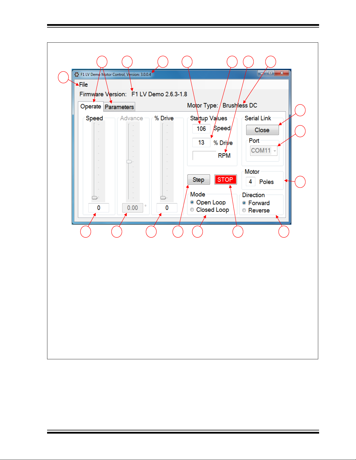
FIGURE 1-1:
1
11
121718
2 3 4 5 6 7 8
9
16
10
1315 14
1. Motor Parameters pull-down menu. Save
and recall to and from disc.
2. Speed control (relative 0 to 255):
• Commutation rate in open loop
• Drive level in closed loop
3. Zero cross advance/retard (BLDC only).
4. Motor drive voltage control (open loop). In
BLDC closed loop this control reverts to a
balance control.
5. BLDC open-loop single-step button.
6. Open/closed-loop control selection (BLDC
and stepper motors only).
7. Panic STOP button – Forces drive and com-
mutation to zero.
8. Motor direction selection.
9. Number of motor poles (BLDC only).
10. Serial port selection.
11. Serial link Open/Close button.
12. Motor type indicator.
13. Motor RPM – click label to update.
14. Initial drive level for start-up.
15. Initial speed setting for start-up.
16. PC Software version.
17. F1 LV Evaluation Platform software version.
18. Run time and static motor parameters tabs.
F1 LV Evaluation Platform Overview
2012 Microchip Technology Inc. DS41629A-page 15
Page 16
F1 LV Evaluation Platform Motor Control Add-ons
19
20
21
33 32
22 23 25 26 2724
28
29
31 30
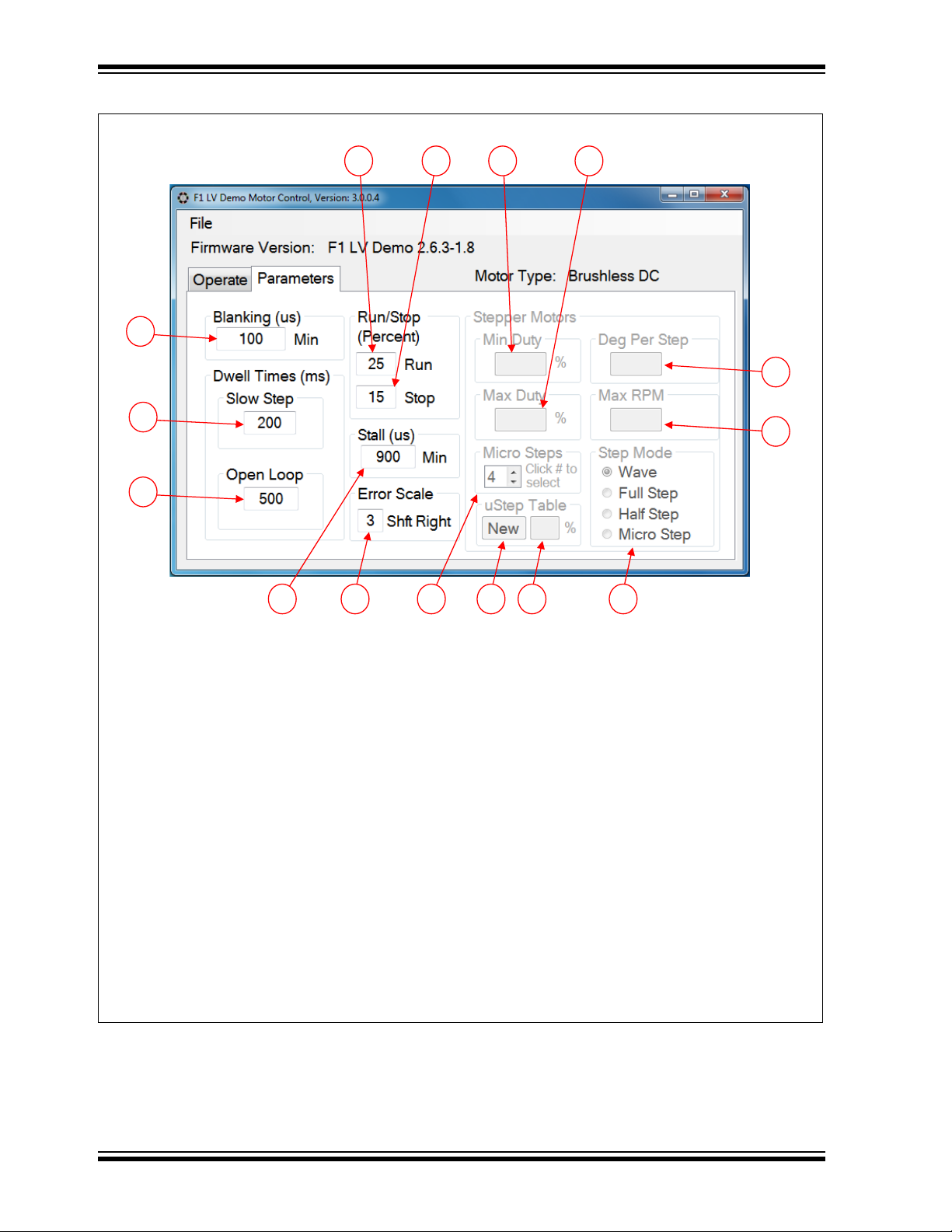
19. BLDC flyback voltage blanking time.
20. BLDC dwell time at each start-up step.
21. BLDC milliseconds to remain in Open-Loop
mode at start-up before closing the loop.
22. BLDC minimum commutation time below
which a stall is detected.
23. BLDC error feedback multiplication factor.
Each shift divides error by 2.
24. Stepper motor steps in each drive phase
when microstepping is selected.
25. Button to invoke new microstep sinusoid
drive look-up table.
26. Peak drive level in microstep look-up table.
27. Stepper motor commutation mode selection.
28. Stepper motor maximum RPM commutation
rate when speed control is set at maximum.
29. Degrees per step physical attribute of the
attached motor.
30. Maximum drive voltage duty cycle applied
when speed control is at the maximum
RPM. This prevents excessive overdrive of
the motor.
31. Stepper motor drive voltage duty cycle
applied when speed control is at the lowest
run speed above stop.
32. Percent of speed control setting, relative to
maximum, below which the motor drive is
removed and the motor is stopped.
33. Percent of speed control setting, relative to
maximum, above which the motor starts
from a stopped state.
FIGURE 1-2:
DS41629A-page 16 2012 Microchip Technology Inc.
Page 17

F1 LV Evaluation Platform Overview
1.4 USING THE F1LVDEMO CONTROL SOFTWARE
1.4.1 Software Updates
The software supplied and preloaded into the F1 LV Evaluation Platform supports all
four of the add-on motor control boards. The preloaded software is the latest version
available at time of manufacture. Source code including any updates is available for
free download from the Microchip web site: www.microchip.com/F1Eval
All motors can be controlled with the PC-based F1LVDemo control GUI. The
F1LVDemo control software is available for free download from the Microchip web site:
www.microchip.com/F1Eval
1.4.2 Serial Link
The F1LVDemo control GUI operates through a USB to serial interface that appears as
a standard RS-232 serial port to the PC operating system. The USB interface on the
F1 LV Evaluation Platform is an MCP2200 USB to Serial interface device. Ensure that
the drivers for this interface are loaded in the PC before making the connection. Interface drivers can be downloaded for free from the MCP2200 product page of the Microchip web site.
1.4.3 Connecting the F1 LV Evaluation Platform to the Add-on Board
.
.
Perform the following steps in the order shown to establish the link between the
F1LVDemo control software and the F1 LV Evaluation Platform.
1. Connect the desired add-on board to the F1 LV Evaluation Platform J3.
2. Connect the supplied motor to the add-on board.
3. Ensure the following jumpers are in place on the F1 LV Evaluation Platform:
• J10 – Pot Enable
• J9 – Temperature Sense Enable
• J4 – I Sense break
• J6 – Expansion Board Power
4. Turn the RF2 potentiometer fully counter clockwise.
5. Each add-on board is equipped with a linear 3.3 Volt regulator that supplies
power to the F1 LV Evaluation Platform.
Apply 9-12 V
2.5 mm power jack or directly to the appropriate pins of the add-on board motor con-
nector. The power jack connector is designed to accept 9 V
former. The center pin is the positive terminal. When power is applied the F1 LV
Evaluation Platform LCD will display the motor type and add-on board revision.
At this point the motor can be operated stand-alone with the potentiometer on the F1
LV Evaluation Platform. Additional motor controls are accessible only with the control
GUI.
DC power to the add-on board. Power can be applied through the black
DC, 0.75 amp wall trans-
1.4.4 Connecting the F1 LV Evaluation Platform to the PC
6. Connect a USB cable from the PC to the F1 LV Evaluation Platform J2.
7. Execute the F1LVDemo program.
8. Select the communication port associated with the F1 LV Evaluation Platform.
This will most likely be the highest numbered communication port in the selection
box.
9. The communication port list is built during the F1LVDemo program initialization.
If you connect to the board after the program is started, the communication port
will not appear in the selection list.
2012 Microchip Technology Inc. DS41629A-page 17
Page 18

F1 LV Evaluation Platform Motor Control Add-ons
10. Click the Open button. After the link to the F1 LV Evaluation Platform is estab-
lished, the F1 LV Evaluation Platform software version will be displayed, as well
as the detected motor type.
When the link is established, all user accessible motor parameters stored in the add-on
board will be retrieved and shown in the corresponding controls of the GUI. Controls
not applicable to the detected motor will be disabled and grayed out.
1.4.5 Open Versus Closed Loop
The open-loop and closed-loop selections apply only to brushless DC and stepper
motors. In open-loop operation, the motor voltage and speed controls are independent.
In closed-loop operation the speed control functions as the control for both the speed
and voltage.
Brushless DC is truly a closed-loop operation where the applied voltage is set with the
speed control and the motor speed responds automatically to keep the back EMF
voltage equal to the applied voltage.
Stepper motor closed-loop operation is technically not closed loop. Both the motor
voltage and speed outputs simultaneously follow the single-speed control input as
independent open-loop functions of the minimum and maximum speed and drive
parameters.
1.4.6 Changing Motor Parameters
To change a motor parameter, type the new value into the corresponding text box. The
initial key press clears the previous value and changes the value to red. Red indicates
that the value has not been sent to the Platform RAM. When the enter key is pressed
the value is immediately sent to the Evaluation Platform RAM and the display returns
to the default black. The entry can be terminated without updating the Platform RAM
by pressing the Escape key. Changed parameters reside in volatile RAM only. Any
Platform Reset will restore the RAM values to those in the Platform EEPROM memory.
Unexpected Platform Resets will cause inconsistencies between the parameters
displayed in the GUI and those in the Platform RAM. Select the pull-down menu
File->RAM->Display
Platform RAM.
option to resynchronize the displayed values with those in the
1.4.7 Saving and Restoring Motor Parameters
Sometimes it is useful to try many different motor setups when optimizing performance.
Setups can be saved to disc storage with the pull-down menu File->Save…
Previously stored setups can be recovered with the pull-down menu File->Open…
option. Parameters retrieved from disc update both the display and the Platform RAM.
When the optimum setup is determined those parameters can be saved to the Platform
nonvolatile memory with the pull-down menu File->RAM->EEPROM
Parameters saved to EEPROM will be restored to RAM on every Platform Reset. The
values in the Platform EEPROM can be restored to RAM without a Reset with the
pull-down menu File->EEPROM->RAM
The EEPROM can also be restored to the factory defaults with the pull-down menu
File->Defaults->EEPROM
the source code and programming the Platform program memory after recompiling the
source code.
option. The factory defaults can be altered only by changing
option.
option.
option.
DS41629A-page 18 2012 Microchip Technology Inc.
Page 19

F1 LV Evaluation Platform Overview
1.4.7.1 CATASTROPHIC RECOVERY
In the unlikely event the UNI/O memory becomes erased or damaged, the memory can
be completely restored with the File->Restore->(add-on type)
should only be used if the add-on board fails the automatic detection process. Take
care to select the add-on type corresponding to the attached board. Failure to do so will
cause unexpected operation possibly resulting in permanent damage to the add-on
board hardware.
1.4.8 Hints for Optimum Performance
The BLDC and stepper motors are interrupt driven. The motor commutation interrupts
take precedence over all other operations. All services other than the motor commutation are polled. When the motor is operating at very rapid commutation rates, the time
for other services can become severely limited. For most situations, the serial link service is able to keep up with the activity from the PC. However, when a rapid series of
commands is coupled with rapid commutations, the serial link can appear to stall. To
avoid this situation, use the slider controls for only small and slow changes. Enter numbers directly into the slider text box when a large change to the slider control is desired.
If a stalled control condition occurs, try to regain control by clicking on the red STOP
button. If that does not restore control, the last resort is to press the F1 LV Evaluation
Platform MCLR button.
option. This option
1.4.9 Header File Versus GUI Motor Parameters
The default motor parameters are defined in the F1 LV Evaluation Platform source code
motor header files. The following table correlates the GUI parameters with the equivalent header file parameters. The conversion factor is the value by which the header file
parameter is multiplied to derive the GUI parameter. In all cases, whether in the table
or text, parameters expressed as all caps may be found exactly as shown in the header
files.
See Appendix B. “Conversion Factors” for more information on the parameters and
the associated conversion factors.
2012 Microchip Technology Inc. DS41629A-page 19
Page 20

F1 LV Evaluation Platform Motor Control Add-ons
TABLE 1-2:
Motor Type GUI Parameter Header File Parameter
BLDC
(EBM)
BDC
(PAN14)
Unipolar
(42HS03)
and
Bipolar
(39HS)
STEPPER
Start-up: Percent Drive MED_START_DRIVE_PCT 1
Start-up: Speed (RPM) START_RPM 1
Poles NUM_POLES 1
Blanking BLANKING_COUNT_us 1
Slow Step TIMEBASE_SLOW_STEP 10
Open Loop OPEN_LOOP_ms 1
Stall STALL_COUNT_us 1
Run Percent LOW_RESTORE_REQUEST_PCT 1
Stop Percent LOW_OFF_REQUEST_PCT 1
Error Scale ERROR_SCALE 1
Run Percent LOW_RESTORE_REQUEST_PCT 1
Stop Percent LOW_OFF_REQUEST_PCT 1
Run Percent REQUEST_ON 0.392
Stop Percent REQUEST_OFF 0.392
Min. Duty Percent MIN_DUTY 0.392
Max. Duty Percent MAX_DUTY 0.392
Degrees per Step MOTOR_STEP_ANGLE 0.1
Max RPM MAX_RPM 1
uStep Table Bipolar_CCP_Val[]
Unipolar_CCP_Val[]
Conversion
Factor
Varies
DS41629A-page 20 2012 Microchip Technology Inc.
Page 21

Chapter 2. The BLDC Add-on Board
2.1 OVERVIEW
The BLDC add-on (DM164130-2) allows you to drive virtually most sensorless
three-phase brushless DC motors used in consumer electronics, ranging from small
HVAC applications to complex media reading/writing drives. The add-on is shipped
together with the ebm-papst BLDC motor, to which it connects through a ribbon cable
to a special connector on the board (J5). Alternatively, any other 5-12V BLDC motor
can be used by hooking it up through the J2 connector.
2.1.1 Features
The key features of this board include the following:
Connectors:
• Male 20-pin connector (J1) to match the F1 LV Evaluation Platform
• Generic 6-pin BLDC motor connector (J2)
• 6-pin ebm-papst motor interface (J5)
• 5-12V power supply input connector (J4)
Typical BLDC drive:
• Three P-type and 3 N-type MOSFETs forming three half bridges for the three
• Six bipolar transistors to command the MOSFETs
• Sensing resistor for current measurement (R15)
Control:
• R21 for adjusting the zero crossing voltage
• R19 for adjusting the over-current Fault detect (software for this function is not
F1 LV EVALUATION PLATFORM
MOTOR CONTROL ADD-ONS
motor phases
implemented).
Note: The function labels on these two controls are reversed on the R2 revision
of these boards.
Protection:
• Power fuses (F1, F2)
Power supply:
• 3.3V voltage regulator (U1)
2.1.2 What’s Included
The BLDC add-on part number (DM164130-2) contains:
• BLDC Add-on Board designed for the F1 Evaluation Platform
• ebm-papst motor (P/N: VD-3-25.07)
• 28 AWG ribbon cable to match the ebm-papst motor
2012 Microchip Technology Inc. DS41629A-page 21
Page 22

F1 LV Evaluation Platform Motor Control Add-ons
2.1.3 Reference Documents
This section points you to technical application support.
AN857, ”Brushless DC Motor Control Made Easy”
AN885, ”Brushless DC (BLDC) Motor Fundamentals”
AN899, ”Brushless DC Motor Control Using PIC18FXX31 MCUs”
AN970, ”Using the PIC18F2431 for Sensorless BLDC Motor Control”
AN1305, ”Sensorless 3-Phase Brushless Motor Control with the PIC16FXXX”
You can obtain these reference documents from your nearest Microchip sales office
(listed in the last page of this document) or by downloading them from the Microchip
web site.
2.2 BOARD SETUP
WARNING
The BLDC Motor Control Add-on Board is intended to drive three-phase brushless DC
motors. Before connecting the motor, make sure the power rating of the motor is equal
to or less than the power rating of the board, as shown in Appendix B. “Conversion
Factors”. Also, make sure the configuration parameters inside the software or the GUI
are correct for the motor you are using. Failure to comply with this warning could lead
to malfunction of the board and the motor, and could result in physical harm.
Before beginning the start-up procedure, complete a visual check of the board and the
motor for connectivity and mechanical damage. If damage is found, DO NOT power-up
the board. Otherwise, you may further damage the equipment. Contact Microchip’s
local office or distributor immediately.
A step-by-step connecting procedure is available in Section 1.4.3 “Connecting the
F1 LV Evaluation Platform to the Add-on Board”. If using the ebm-papst motor,
attach the ribbon cable from the motor at step 2. Also, make sure that POR R4 on the
evaluation platform is turned fully CCW.
If using a different motor, connected through J2, please keep in mind to attach each
motor phase firmly to the connector. The red connector supplied with the board is
designed to accept 22 AWG wire. Bad contacts can damage the add-on and will wear
out the motor in time. There is no rule for attaching a specific motor lead to a phase line
on the add-on. Keep in mind the correspondences on the software side when testing
or measuring directly on that motor phase.
Adjust R21 90 degrees CCW from the mid-point CCW when operating the ebm-papst
motor. R21 should be set to its mid-point for other motors.
2.3 HARDWARE
2.3.1 General Architecture
The BLDC add-on uses a typical three half-bridges control configuration suitable for
three-phase BLDC motors, using six MOSFETS commanded through six bipolar
transistors. Sensorless control is done in the software without any other external
components.
Figure 2-1 provides a simplified block diagram of the development board hardware,
coupled to the F1 LV Evaluation Platform:
DS41629A-page 22 2012 Microchip Technology Inc.
Page 23
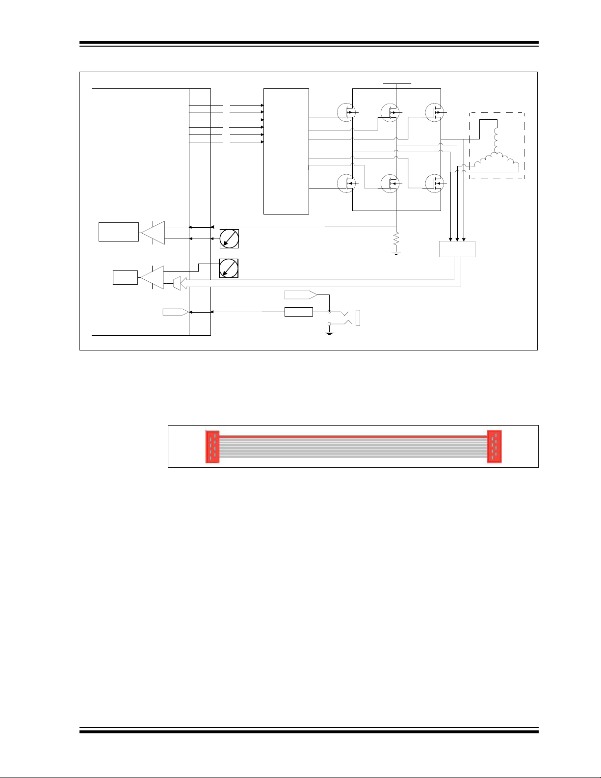
The BLDC Add-on Board
PIC16LF1947
J1
Bipolar
Transistor
Inverter
Q1
Q7
V_MOTOR
R15
J3
V_MOTOR
VinVout
U1
3.3V
_
+
Current meas.
autoshutdown
Q8
Q9
U
VW
R19
R21
_
+
Scaling
Zero
Cross
Q2
Q3
HU
LU
HV
LV
HW
LW
VU, VV, VW
Motor
+
_
FIGURE 2-1: THE BLDC MOTOR CONTROL ADD-ON ARCHITECTURE
2.3.2 Attaching the Motor
The BLDC add-on kit includes the three-phase 24V ebm-papst motor. This motor can
be attached through a dedicated 28AWG 8-wire ribbon cable using connector J5.
FIGURE 2-2: THE EBM-PAPST MOTOR CONNECTOR
However, you can use your own three-phase BLDC motor by attaching its leads to the
J2 connector. The red connector supplied with the board is designed to accept 22 AWG
wire.
2.3.3 Power-Up
Voltage is supplied through the 2.5 mm jack connector J4, with a maximum rating of
+12 V
DC. The F1 LV Evaluation Platform should be configured to use expansion board
power by inserting the power jumper on J6. See the “F1 LV Evaluation Platform for
Enhanced PIC
®
Microcontrollers User’s Guide” (DS41614A) for more details.
2.3.4 Power Stage
The BLDC add-on incorporates the classic three half-bridges drive made from P and
N-type MOSFETs (for more details, please refer to the BLDC board schematic in
Appendix A. “Board Layout and Schematics”). The maximum current rating is 8A
on each MOSFET. Please keep this in mind when designing your application or
modifying the add-on hardware.
The stage contains six PWM (HU, LU, HV, LV, HW, LW) inputs and three back EMF
sense outputs (VU, VV, VW). The BLDC motor attaches to the three driver outputs (U,
2012 Microchip Technology Inc. DS41629A-page 23
V, W) .
Page 24

F1 LV Evaluation Platform Motor Control Add-ons
Motor current is measured by using the R15 shunt resistor, placed in-between the
Power Stage lowside and ground, and connected to the PIC16F1947 through the J1
connector. (Current sensing is not implemented in the F1 LV Evaluation software.)
2.3.5 Protection
Two 5A fuses (F1 and F2) are used to protect your add-on in case of an overcurrent
situation in the output drivers. In case one or both of them get burnt, remove power
immediately from the board and inspect the add-on for further damage. Do not replace
the burnt fuses with other values than the ones provided with the board.
2.3.6 Speed Control
Speed control can be performed through either the Motor Control GUI or the 10K POT
R4 located on the F1 LV Evaluation Platform.
2.4 DEMO SOFTWARE
2.4.1 Introduction
The F1 LV Evaluation demonstration program uses a single combined demo. The
combined demo source code is organized into sectional code for ease of
accommodating several motor types. This chapter provides an overview to the
functions provided by the BLDC demo.
The BLDC demo code is designed to operate a sensorless BLDC control. The software
can be easily tuned to the needs of your application or motor by changing the
parameters on-the-fly, by modifying the motor parameters in the F1LVDemo GUI.
2.4.2 The Motor Control GUI Application
Using the Motor Control Application GUI, you can change the following parameters:
• Motor poles number
• Speed [arbitrary range 0 to 255]
• The timing balance between zero-cross and commutation periods [degrees]
• Phase advance [degrees]
• Start-up speed [arbitrary range 0 to 255]
• Drive voltage [% of full scale]
• The minimum blanking period [us]
• Dwell timings: closed-loop slow stepping [ms] and open loop [ms]
• Run/stop hysteresis drive voltage [% of full scale]
• Minimum motor stalling period [us]
• Error scaling factor [divisor power of 2].
Also, the motor can be run in open/closed loop and forward/reverse.
Clicking on the ‘RPM’ text in the Operate tab will display the motor speed in the text
box next to it.
DS41629A-page 24 2012 Microchip Technology Inc.
Page 25

The BLDC Add-on Board
2.4.3 BLDC Parameter Optimization
Brushless motors depend on the software to commutate the motor. The software must
determine the rotor position relative to the stator so as to commutate the driver circuitry
at specific rotor positions. The rotor position is determined in sensorless motors by
voltages induced into the stator by rotor motion. The induced voltage is referred to as
back EMF or BEMF. When the rotor is stationary, there is no BEMF from which to
determine the rotor position. Starting the motor requires commutating the motor blindly,
without the benefit of feedback, to start the rotor in motion fast enough to sense the
BEMF, and close the loop on rotor position for commutation.
The motor speed, in response to the applied voltage, varies by motor design. We need
to match the initial drive voltage and open-loop commutation rate to the motor to
accomplish two objectives:
1. prevent excessive current in the motor
2. start rotation fast enough to sense the BEMF
When the motor is running, the BEMF on the driven pair of stator windings matches the
applied voltage. The BEMF on the undriven winding starts at one power rail at the
beginning of the commutation period and ends at the other power rail at the end of the
commutation period. However, this is only true when the motor is running at the design
speed. At any other speed, the BEMF is effectively undetectable. Unfortunately, the
motor will not start if we apply a voltage, and then commutate at the rate for which the
motor is designed. To start the motor, we need to commutate slower than the design
rate and then ramp up to the design speed.
The task of motor optimization is to find a combination of applied voltage and
commutation rate for which the motor will start to rotate. From there, the control
algorithm will ramp-up the commutation rate to where the BEMF can be sensed. The
Motor Control GUI enables us to independently set the applied motor voltage and
commutation rate to find a combination that works. Use the following steps to
experiment with your motor optimization:
1. Set POT R21 to middle range for your motor or 90 degrees CCW from the middle
range for the ebm-papst motor supplied with the BLDC Add-on Board.
2. Select Open-Loop mode.
3. Set the speed control to a nominal rate, such as 100.
4. Slowly increase the % Drive control until the motor starts to turn.
5. Slowly increase the speed control until it is just faster than the motor can go.
6. Slowly reduce the speed control until the motor starts to rotate again.
7. Note the % Drive setting, then enter 0 into the % drive control text box.
8. Re-enter the % drive setting noted in step 6, and observe that the motor starts
spinning.
9. Repeat steps 7 and 8 to verify the motor always starts reliably. If it does not, then
reduce the speed control slightly and repeat steps 6, 7 and 8.
10. When you are satisfied with the start response obtained by steps 6, 7 and 8, then
enter the final speed control value into the Speed Start-up value text box. The
equivalent RPM will be displayed.
Note: The displayed RPM value is only accurate if the motor has the number of
poles indicated. The number of poles only matters if you want the RPM
value to represent the mechanical operation. If you are not sure how many
poles your motor has, then you can determine this by leaving the % Drive
where it is, setting the speed to zero, and count the number of Step button
clicks it takes to make one full motor revolution. Divide this number by
three, that is the number of poles.
2012 Microchip Technology Inc. DS41629A-page 25
Page 26

F1 LV Evaluation Platform Motor Control Add-ons
11. Enter the % Drive number into the % Drive start-up value.
12. Click the Parameters tab and verify or enter the following nominal values:
a) Blanking: 100 us
b) Slow Step: 200 ms.
c) Open Loop: 500 ms.
d) Run: % Drive entered in step 13.
e) Stop: 2 less than Run
f) Stall: 900 us
g) Error Scale: 3
13. Click the Operate tab and select Closed-Loop mode.
14. Hold your breath, cross your fingers, and slowly increase the speed control to the
point where the motor starts. With any luck, your motor will start and immediately
lock onto the BEMF feedback to become fully operational in Closed-Loop mode.
When that happens, you can increase the speed control to the desired rate. Click
on the RPM label to perform one reading of the motor RPM.
Now that you are able to operate the motor in closed loop, at least at slow speed, you
need to complete the optimization of the other motor parameters. The following
procedures describe each parameter and its adjustment.
2.4.3.1 BLANKING
The blanking interval is required so the BEMF sense does not falsely trigger on the
flyback voltage caused by commutation. You can observe this pulse on any motor lead
while the motor is running. The flyback pulse voltage occurs immediately following the
unmodulated drive period. The width of the flyback pulse varies depending on the
inductance of the motor windings and the motor load current. Measure this pulse under
worst-case motor operation and set the blanking time to at least the measured time
plus some margin. The blanking time must be less than 50% of the minimum
commutation period, and ideally much less than that. You may notice during
measurement that some modulation pulses immediately following the flyback pulse
extend beyond the mid-level of the drive voltage. Treat those pulses as part of the time
that must be blanked.
2.4.3.2 SLOW-STEP DWELL TIME
During start-up, the motor windings are energized for a short period to pre-position the
rotor. Slow step is the length of time that the windings are energized. Large high inertia
motors take longer to reach the position, and therefore need extra time. Experiment
and use the shortest time that works.
2.4.3.3 OPEN-LOOP DWELL TIME
The open-loop time is the amount of time that the motor operates in Open-Loop mode
before the ramp-up to BEMF detection starts. The open-loop voltage and commutation
rate is the same that you entered in the start-up parameters. Small low inertia motors
start well going straight from slow step pre-position into the ramp-up to BEMF
detection. For those motors you can enter an open-loop time of zero. Larger motors
need time to stabilize at the open-loop rate before ramping up. Experiment to find the
value that works best for your motor.
2.4.3.4 RUN/STOP PERCENTAGE
The run value should match the start-up drive value to ensure a smooth transition from
open loop to ramp-up. Once BEMF lock is obtained, most motors are able to maintain
lock below the start-up drive value. Experiment to find the stop value that ensures
reliable motor operation at slow speed.
DS41629A-page 26 2012 Microchip Technology Inc.
Page 27

The BLDC Add-on Board
2.4.3.5 STALL
A motor that stalls may appear to the control algorithm as if it is still running at high
speed. Blanking, modulation, and intrinsic motor characteristics all play a part in a false
BEMF indication. When this happens, the commutation rate will ramp up to a rate much
higher than the motor is able to operate. This feature is used to detect a stall condition.
Determine an appropriate stall detection time by measuring the commutation period of
the motor at maximum speed. Enter this period minus some margin as the stall period.
If the commutation period is ever shorter than the stall period, then the motor will be
immediately stopped.
2.4.3.6 ERROR SCALE
The control algorithm compares the actual time from commutation to where the BEMF
crosses the mid-drive level. This is referred to as the zero cross event. The zero cross
event is expected half way through the commutation period. The error between the
expected and actual measured time is scaled down by the error scale factor and added
back into the commutation time, thereby forming the closed-loop operation. The error
scale value determines the loop gain. Less gain will result in a slower, but more stable
response. Conversely, higher gain will result in a faster response, but less stable
operation. The error is scaled by performing right shifts on the error value. More shifts
means less of the error is getting back into the loop, resulting in less loop gain. The
commutation time is a 16-bit integer with a 17
will use all 16 bits. BEMF error for slow motors can be large so a correspondingly large
error scale can be tolerated. However, as the motor speed increases the commutation
time decreases and not all 16 bits are significant. At very high speeds the magnitude
of the error is small relative to the full 16-bit number and large error scales cannot be
tolerated, because the full error value may be shifted to a value of zero. For most
motors, an error scale value of three works well. Again, experiment to see what works
best for your particular motor.
th
sign bit. Very slow commutation rates
2.4.3.7 ADVANCE AND BALANCE CONTROLS
The advance and balance controls should be maintained at zero for normal motor
operation. These controls are only used to observe the effects of manipulating the zero
crossing event. The advance control advances or retards the zero crossing event. The
balance control extends or shortens the commutation time after the zero crossing
event. It is interesting to observe on an oscilloscope how the motor reacts to these
disturbances.
2.4.3.8 ZERO-CROSSING ADJUSTMENT
A potentiometer, R21, is included on the BLDC Add-on Board for adjusting the zero
crossing reference voltage. Most motors require a reference voltage of half the applied
motor voltage. However, the winding pattern of some motors results in a nonlinear
BEMF response. Such a motor is the ebm-papst motor supplied with the add-on board.
This motor has an S-shaped BEMF response and operates best when the zero
crossing reference is lower than half the applied motor voltage. If you have difficulty
starting the motor, even after going through all the optimization steps, then check the
position of R21 and try moving the position slightly more and less than the 90 degree
CCW starting position. Once you get the motor operating in closed loop, fine tune the
zero crossing reference with R21. This is accomplished by observing the waveform of
one of the motor terminals. Adjust R21 so that the rising and falling slopes of the
waveform are equal in appearance.
2012 Microchip Technology Inc. DS41629A-page 27
Page 28

F1 LV Evaluation Platform Motor Control Add-ons
NOTES:
DS41629A-page 28 2012 Microchip Technology Inc.
Page 29

Chapter 3. The Brushed DC Add-on Board
3.1 GETTING STARTED
3.1.1 Overview
The BDC add-on (DM164130-6) allows you to drive virtually most brushed DC motors
used in consumer electronics. The add-on is shipped together with the NMB brushed
DC motor (PAN14EE12AA1) mounted on the board. The motor voltage is supplied
through jumper J5. Alternatively, any other 5-12V BDC motor can be used by hooking
it up through the J4 connector and removing the shorting block from J5.
3.1.2 Features
The key features of this board include the following:
Connectors:
• Male 20-pin connector (J1) to match the F1 LV Evaluation Platform
• Generic 4-pin BLDC motor connector (J4) for 22 AWG wire
• 5-12V power supply input connector (J3)
Typical BDC drive:
• Two N-type and two P-type MOSFETs arranged as an H-bridge
• Four NPN bipolar transistors to command the MOSFETs
• Sensing resistor for current measurement (R15)
Control:
REF POT, for general over-current adjustment (over-current detection is not
•V
implemented in the demo software).
Protection:
• 5A power fuses (F1, F2)
Power Supply:
• 3.3V voltage regulator (U1)
Parameter storage:
• 128 x 8 UNI/O
F1 LV EVALUATION PLATFORM
MOTOR CONTROL ADD-ONS
®
Serial EEPROM (U2)
3.1.3 What’s Included
The BDC add-on with part number DM164130-6 contains:
• BDC Add-on Board designed for the F1 Evaluation Platform
• NMB motor (P/N: PAN14EE12AA1)
2012 Microchip Technology Inc. DS41629A-page 29
Page 30

F1 LV Evaluation Platform Motor Control Add-Ons
3.1.4 Reference Documents
This section points you to application technical support.
AN696, PIC18CXXX/PIC16CXXX DC Servomotor
AN718, Brush-DC Servomotor Implementation Using PIC17C756A
AN893, Low-Cost Bidirectional Brushed DC Motor Control Using the PIC16F684
AN905, Brushed DC Motor Fundamentals
You can obtain these reference documents from your nearest Microchip sales office
(listed in the last page of this document) or by downloading them from the Microchip
web site.
3.2 BOARD SETUP
WARNING
Before connecting the motor, make sure the power rating of the motor is equal to or
less than the power rating of the board, as shown in Appendix B. “Conversion Factors”. Also, make sure the configuration parameters inside the software or the GUI are
correct for the motor you are using. Failure to comply with this warning could lead to
malfunction of the board and the motor, and could result in physical harm.
Before beginning the start-up procedure, complete a visual check of the board and the
motor for connectivity and mechanical damage. If damage is found, DO NOT power-up
the board. Otherwise, you may further damage the equipment. Contact Microchip’s
local office or distributor immediately.
A step-by-step connecting procedure is available in Section 1.4.3 “Connecting the
F1 LV Evaluation Platform to the Add-on Board”. Please make sure that POT R4
on the Evaluation Platform is turned fully CCW.
To connect either the NMB motor (with Jumper J5) or a brushed DC motor of your
choice (through terminals V and U of add-on connector J4), keep in mind to attach each
motor phase firmly to the connector. Bad contacts can damage the add-on and will
wear out the motor in time. There is no rule for attaching a specific motor lead to a
phase line on the add-on. Keep in mind the correspondences on the software side
when testing or measuring directly on that motor phase.
3.3 HARDWARE
3.3.1 General Architecture
The BDC add-on uses a typical H-bridge control configuration suitable for two-phase
BDC motors, using four MOSFETS commanded through four bipolar transistors. The
demo software varies the motor speed by pulse-width modulating the H-bridge drive.
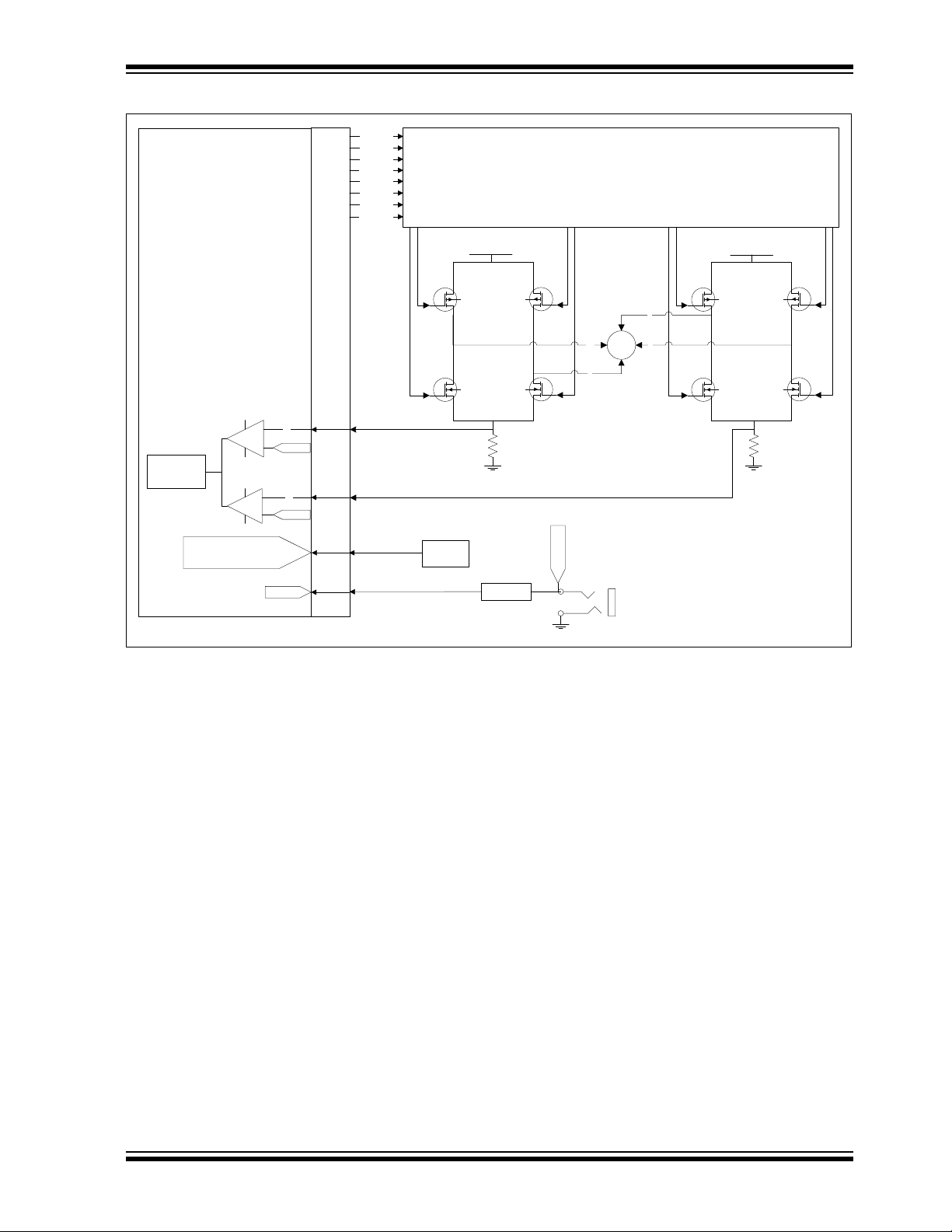
Figure 3-1 provides a simplified block diagram of the development board hardware,
coupled to the F1 LV Evaluation Platform:
DS41629A-page 30 2012 Microchip Technology Inc.
Page 31

The Brushed DC Add-on Board
PIC16LF1947
J1
Bipolar Transistor Command Bridge
A
B
C
D
Q1
Q5
U
Q2
Q6
V
V_MOTOR
ISENSE
Current
measurement
+
-
R15
J3
V_MOTOR
VinVout
U1
3.3V
R13
VREF
1K
EEPROM
Detect add-on type
read/write parameters
IRef
FIGURE 3-1: THE BDC MOTOR CONTROL ADD-ON ARCHITECTURE
3.3.2 Attaching the Motor
The BDC add-on kit includes a 12V NMB PAN14EE12AA1 motor. This motor is
mounted on the board. The voltage is supplied to the motor through jumper J5. To use
an alternate motor, remove the shorting block from J5 and attach the two motor leads
to lines V and U. The V_MOT and GND connections are for a lab supply and are to be
used in lieu of the 2.5 mm power connector.
3.3.3 Power-Up
Voltage is supplied through the 2.5 mm jack connector J3, with a maximum rating of
+12VDC. The F1 LV Evaluation Platform must be configured to use expansion board
power by inserting the power jumper on J6. See “F1 LV Evaluation Platform for
Enhanced PIC
3.3.4 Power Stage
The BDC add-on incorporates the classic full H-bridge drive made from two N-type and
two P-type MOSFETs. The maximum current rating is 8A on each MOSFET. Please
keep this in mind when designing your application or modifying the add-on hardware.
®
Microcontrollers User’s Guide” (DS41614) for more details.
2012 Microchip Technology Inc. DS41629A-page 31
Page 32

F1 LV Evaluation Platform Motor Control Add-Ons
The stage contains four PWM (A, B, C, D) inputs and two driver outputs (VU and VV)
to be attached to each terminal of the BDC motor (U, V).
The current on the H-bridge is measured on the R15 shunt resistor, placed in-between
the Power Stage lowside and ground, and connected to the PIC16F1947 through the
J1 connector.
3.3.5 Protection
Two 5A fuses (F1 and F2) are used to protect your add-on in case of an overcurrent
situation in the output drivers. In case one or both of them get burnt, remove power
immediately from the board and inspect the add-on for further damage. Do not replace
the burnt fuses with other values than the ones provided with the board.
3.3.6 UNI/O® Memory Chip
The UNI/O® memory chip stores the board ID and the application parameters. It is
accessed by the Motor Control GUI at start-up in order to recognize which of the four
boards is attached to the F1 LV Evaluation Platform, thus loading the appropriate
parameters for the add-on used.
3.3.7 Speed Control
Speed control can be performed through either the Motor Control GUI, or the 10K POT
R4 found on the F1 LV Evaluation Board.
3.4 DEMO SOFTWARE
3.4.1 Introduction
The F1 LV Evaluation demonstration program uses a single combined demo. The
combined demo source code is organized into sectional code for ease of
accommodating several motor types. This chapter provides an overview to the
functions provided by the BDC demo.
The BDC demo code is designed to operate a brushed DC motor. All that is needed to
operate a brushed DC motor is a supply voltage, because brushed DC motors self
commutate. The only adjustable parameters for brushed DC motors are the start and
stop thresholds. Voltage is applied to the motor when the speed control is greater than
the Run percent, and is removed when the speed control is less than the Stop percent.
3.4.2 The Motor Control GUI Application
Using the Motor Control Application GUI, you can change the following parameters:
• Speed [arbitrary range 0 to 255]
• Run/Stop hysteresis drive voltage [% of full scale]
The demo is designed to operate a brushed DC motor in an Open-Loop mode only.
Also, the motor can be run either forward or reverse.
Voltage control is the most simple control method for DC motors. It is based on a
directly proportional relationship between the applied voltage and speed. Using the
Speed slider in the Motor Control GUI or the POT on the F1 Evaluation Platform to
adjust speed, you actually adjust the amount of voltage applied to the motor.
The Run/Stop hysteresis is configurable through the Run/Stop input boxes in the
Parameters tab of the GUI. The Run percentage is the percentage of full-scale control
input above which the motor will run. The Stop percentage is the percentage of
full-scale control input below which the motor will stop. Separate thresholds allows for
hysteresis in the run control.
DS41629A-page 32 2012 Microchip Technology Inc.
Page 33

Chapter 4. The Bipolar Stepper Add-on Board
4.1 GETTING STARTED
4.1.1 Overview
The bipolar stepper add-on (DM164130-7) allows you to drive common two-phase
bipolar stepper motors used in consumer electronics, ranging from CNCs, printers,
optical disc drives and small load positioning systems. The add-on is shipped together
with the Leadshine 39HS02 bipolar stepper motor pre-wired to plug directly into add-on
connector J3. Alternatively, any other 5-12V bipolar stepper motor can be used by
hooking it up through the J3 connector.
4.2 FEATURES
The key features of this board include the following:
Connectors:
• Male 20-pin connector (J1) to match the F1 LV Evaluation Platform
• Generic 6-pin bipolar stepper motor connector (J3)
• 5-12V power supply input connector (J2)
Typical Bipolar Stepper drive:
• Four P-type and four N-type MOSFETS comprising two full H-bridges each of
which drives one motor phase
• One sensing resistor for current measurement (R3).
Protection:
• 2x5A power fuses (F1, F2)
Power Supply:
• 3.3V voltage regulator (U1)
Parameter storage:
• 1k x 8 UNI/O
F1 LV EVALUATION PLATFORM
MOTOR CONTROL ADD-ONS
®
Serial EEPROM (U2)
4.2.1 What’s Included
The bipolar stepper add-on with part number DM164130-7 contains:
• Bipolar Stepper Add-on Board designed for the F1 Evaluation Platform
• Leadshine motor (P/N: 39HS02)
4.2.2 Reference Documents
This section points you to application technical support.
AN907, ”Stepping Motors Fundamentals”
AN906, ”Stepper Motor Control Using the PIC16F684”
AN822, ”Stepper Motor Microstepping with PIC18C452”
®
AN1307, ”Stepper Motor Control with dsPIC
2012 Microchip Technology Inc. DS41629A-page 33
DSCs”
Page 34

F1 LV Evaluation Platform Motor Control Add-Ons
You can obtain these reference documents from your nearest Microchip sales office
(listed in the last page of this document) or by downloading them from the Microchip
web site.
4.3 GETTING STARTED
WARNING
The Bipolar Motor Control Add-on Board is intended to drive two-phase bipolar stepper
motors. Before connecting the motor, make sure the power rating of the motor is equal
to or less than the power rating of the board, as shown in Appendix B. “Conversion
Factors”. Also, make sure the configuration parameters inside the software or the GUI
are correct for the motor you are using. Failure to comply with this warning could lead
to malfunction of the board and the motor, and could result in physical harm.
Before beginning the start-up procedure, complete a visual check of the board and the
motor for connectivity and mechanical damage. If damage is found, DO NOT power-up
the board. Otherwise, you may further damage the equipment. Contact Microchip’s
local office or distributor immediately.
A step-by-step connecting procedure is available in Section 1.4.3 “Connecting the
F1 LV Evaluation Platform to the Add-on Board”. Please make sure that POT R4
on the F1 Evaluation Platform is turned fully CCW.
If using a different motor, connected through J3, please keep in mind to attach each
motor terminal firmly to the connector. Bad contacts can damage the add-on and will
wear out the motor in time. There is no rule for attaching a specific motor lead to a
phase line on the add-on. Keep in mind the correspondences on the software side
when testing or measuring directly on that motor phase.
On the F1 LV Evaluation Platform, use push button RD2 to step through the application
menu on the LCD display. To have more control over the motor using a real-time communication tool, please refer to the next section.
4.4 HARDWARE
4.4.1 General Architecture
The bipolar stepper add-on uses a simple bipolar stepper drive formed by four independent N-type MOSFETs suitable for two-phase bipolar stepper motors. Open-loop control, closed-loop control, full step, half step, microstepping commutation can be done in
the software.
Figure 4-1 provides a simplified block diagram of the development board hardware,
coupled to the F1 LV Evaluation Platform:
DS41629A-page 34 2012 Microchip Technology Inc.
Page 35
The Bipolar Stepper Add-on Board
PIC16LF1947
J1
Bipolar Transistor Command Bridge
ECCP1_A
ECCP1_B
ECCP1_C
ECCP1_D
Q1
Q3
Q4
Q6
V_MOTOR
CVREF
I2
_
+
R8
J3
V_MOTOR
VinVout
U1
3.3V
1k x 8
EEPROM
Detect add-on type
read/write parameters
ECCP2_A
ECCP2_B
ECCP2_C
ECCP2_D
Q7
Q9
Q10
Q12
I1
_
+
R15
M
W
X
Y
Z
CVREF
Current
control
V_MOTOR
FIGURE 4-1: THE BIPOLAR STEPPER MOTOR CONTROL ADD-ON ARCHITECTURE
4.4.2 Attaching the Motor
The bipolar stepper add-on kit includes the two-phase Leadshine 39HS02 bipolar stepper motor. The supplied motor is pre-wired to a connector that mates with J3 of the
add-on board. The connector is designed to accept 26 AWG wire. Connector terminals
5 and 6, that mate with the board pins 2 and 1 respectively, may be used to wire in a
lab supply in lieu of power connector J2. Use of a lab supply with a current monitor is
recommended as an aid during parameter optimization.
4.4.3 Power-Up
Power is supplied through either the J2 2.5 mm power jack or the power pins of J3. The
default motor parameters assume that the supply voltage is 9 V
ply voltage will require re-optimizing the motor parameters. Monitoring the supply cur-
DC. Changing the sup-
rent during optimization is highly recommended to prevent over driving the motor.
The F1 LV Evaluation Platform must be configured to use expansion board power by
inserting the power jumper on J6. See the “F1 LV Evaluation Platform for Enhanced
®
PIC
Microcontrollers User’s Guide” (DS41614).
4.4.4 Power Stage
The unipolar stepper add-on incorporates the classic two H-bridges drive consisting of
four N-type and four P-type MOSFETs. The maximum current rating is 8A on each
MOSFET. Please keep this in mind when designing your application or modifying the
add-on hardware.
2012 Microchip Technology Inc. DS41629A-page 35
Page 36

F1 LV Evaluation Platform Motor Control Add-Ons
The stage contains eight PWM (ECCP1_A, ECCP2_A, ECCP1_B, ECCP2_B,
ECCP1_C, ECCP2_C, ECCP1_D, ECCP2_D) inputs and four driver outputs (W, X, Y,
Z) to be attached to the bipolar motor terminals. Outputs W and X should be attached
to one motor phase, and outputs Y and Z should be attached to the other motor phase.
The current on each phase is measured using the R8 and R15 shunt resistors, placed
in-between each H-bridge lowside and ground and connected to the PIC16F1947
through the J1 connector.
4.4.5 Protection
Two 5A fuses (F1 and F2) are used to protect your add-on in case of an overcurrent
situation of the supply voltage. In case one or both of them get burnt, remove power
immediately from the board and inspect the add-on for further damage. Do not replace
the burnt fuses with other values than the ones provided with the board.
4.4.6 UNI/O® Memory Chip
The UNI/O® memory chip stores the board ID and the application parameters. It is
accessed by the Motor Control GUI at start-up in order to recognize which of the four
motor control add-on boards had been attached to the F1 LV Evaluation Platform, thus
loading the appropriate parameters for the add-on used.
4.4.7 Speed Control
Speed control can be performed through either the Motor Control GUI or the 10K POT
R4 located on the F1 LV Evaluation Board.
4.4.8 Current Control
The demo software is implemented for control without an actual current feedback.
However, by reading the voltage level on shunt resistors R8 or R15, you can implement
a software overcurrent protection and perform current control.
For example, a chopper circuit, perhaps the most used method of current control in
motor control drives, can be emulated just by using PIC MCU
PIC16LF1947 has a Fixed Voltage Reference of 1.024V selectable as an input to the
internal 5-bit DAC, which in turn can be used by the internal comparators as a reference
on the positive inputs. If we select the minimum 1/32 step in the DAC, we obtain a comparator trigger level of 32 mV, which is sufficient to chop the current to the motor in
order to maintain it under its maximum rating given by the motor manufacturer (1A in
the case of the Leadshine bipolar stepper).
The Enhanced Capture/Compare/PWM modules have built-in features in PWM mode
for automatically shutting down the PWM, if the comparators are triggered and
auto-restarting the PWM, if certain conditions are met (please consult the
PIC16LF1947 data sheet to learn more).
By adjusting the values of the shunt resistors accordingly, you can emulate the chopper
circuitry, thus reducing the costs of external components and saving up precious space
on your board.
®
modules. The
DS41629A-page 36 2012 Microchip Technology Inc.
Page 37
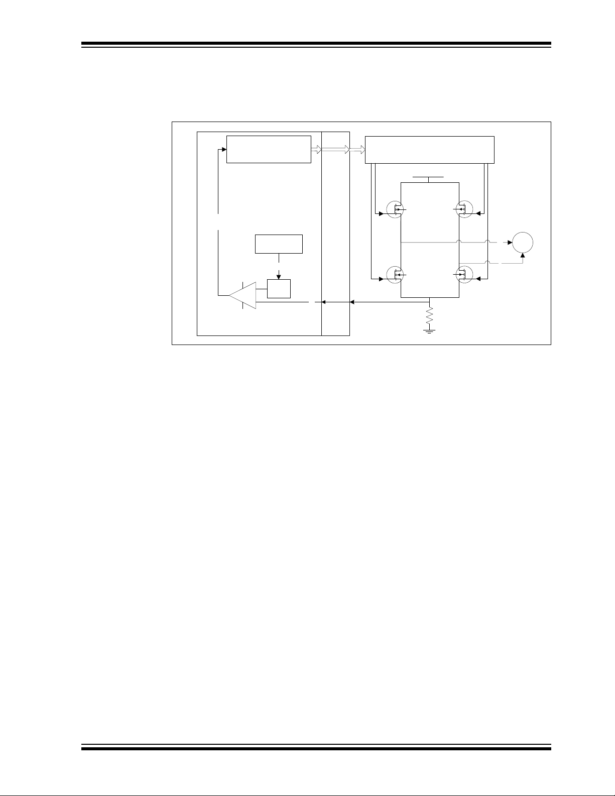
The Bipolar Stepper Add-on Board
PIC16LF1947 J1
Bipolar Transistor
Command Bridge
Q1
Q3
Q4
Q6
V_MOTOR
R8
I1
_
+
M
W
X
DAC
[4:0]
Vdd
GND
FVR
[1.024V:1x/2x/4x]
CMxCON1
CCPxAS
PWMxCON
ECCPx:
PWM Auto-Shutdown
PWM Auto-Restart
Figure 4-2 below gives an insight on how to use the PIC MCU modules as part of a
current chopper:
FIGURE 4-2: CURRENT CHOPPER CIRCUITRY EMULATED WITH
PIC16LF1947 INTERNAL MODULES
4.5 DEMO SOFTWARE
4.5.1 Introduction
The F1 LV evaluation demonstration program uses a single combined demo. The
combined demo source code is organized into sectional code for ease of
accommodating several motor types. This chapter provides an overview to the
functions provided by the bipolar stepper demo.
The bipolar stepper demo code accommodates Full Step, Half Step and Microstep
modes of operation. The software can be easily tuned to the needs of your application
or motor, by modifying parameters in the Motor Control GUI.
4.5.2 The Motor Control GUI Application
Using the Motor Control Application GUI, you can change the following parameters:
• Speed [arbitrary range 0 to 255]
• Maximum speed [rpm]
• Drive voltage [% of full scale]
2012 Microchip Technology Inc. DS41629A-page 37
• The minimum and maximum PWM duty cycle [% of full scale]
• Motor step angle [degrees]
• Run/Stop hysteresis drive voltage [% of full scale]
• Microstepping granularity [1:4, 1:8, 1:16]
• Microstepping look-up table
• Stepping mode [Wave, Full, Half and Microstep]
Also, the motor can be run in open/closed loop and forward/reverse.
Clicking on the ‘RPM’ text in the Operate tab, will display the actual speed in the text
box next to it.
Page 38

F1 LV Evaluation Platform Motor Control Add-Ons
YmXb+=
m = DUTY_SCALE
b = MIN_DUTY
X = speed request (0 to 255)
Y = duty cycle value
m = SPEED_SCALING_CONST
b = 0
X = 1/speed request (0 to 255)
Y = Timer 1 counts in each commutation period
4.6 OPTIMIZING STEPPER MOTOR PARAMETERS
4.6.1 Stepper Motor Closed-Loop Drive Overview
Stepper motor closed-loop operation is technically not closed loop. When Closed-Loop
mode is selected, then both the motor voltage and speed outputs simultaneously follow
the single-speed control input as independent open-loop functions of the minimum and
maximum speed and drive parameters. This section describes how to use the GUI to
optimize the linked speed and drive functions. First, it’s helpful to understand why
simultaneous control of speed and voltage is necessary.
It is the nature of stepper motors to be overdriven. In other words, the voltage and current applied to the motor exceeds what is actually needed to rotate the motor. Ideally,
the excess drive should be kept to a minimum. When the motor is stationary, the
applied voltage needs to be only large enough to keep the motor in position. When
there is no external torque applied to the motor, the stationary drive voltage can be as
low as zero. In order to rotate the motor, a drive voltage must be applied to the motor
coils through drive switches in sequence to progressively rotate the motor to each step
position. The PWM duty cycle to the drive switch determines the effective applied voltage. The rate at which the switches are changed is the commutation rate. As the motor
speed is increased, it takes more drive voltage and current to maintain speed. If the
voltage applied to the motor to maintain the fastest speed were to remain unchanged,
then as the motor slowed, the drive current would increase. To minimize excess current, the voltage applied is a function of the commutation rate. For our purposes, the
relationship between the applied voltage and commutation rate is linear. The general
formula for a linear relationship is:
EQUATION 4-1:
We actually have two linear relationships:
• The relationship between the speed control input and the commutation rate
• The relationship between the speed control input and the PWM duty cycle
The speed control input is an 8-bit number and so has the range from 0 to 255. For any
given speed setting, we need to compute both the commutation time and the duty
cycle.
For the duty cycle calculation the equation substitutions are as follows:
EQUATION 4-2:
For the commutation time the equation substitutions are as follows:
EQUATION 4-3:
DS41629A-page 38 2012 Microchip Technology Inc.
Page 39

The Bipolar Stepper Add-on Board
4.6.2 Optimizing DUTY_SCALE and SPEED_SCALING_CONST
The DUTY_SCALE and SPEED_SCALING_CONST are the slope constants of the two
equations that determine the drive voltage and commutation rate for any given speed
request input. Optimization involves controlling the speed and drive voltage independently to determine the line endpoints. The slope constants can then be calculated from
the endpoints.
The purpose of this exercise is to determine the parameters that will limit the drive current over the operating speed range. Therefore, it is necessary to monitor the supply
current during optimization. Use the following steps to experiment with your motor optimization:
1. Establish the link between the F1LVDemo application and the F1 LV Evaluation
Platform by following the procedure outlined in Section 1.4.3 “Connecting the
F1 LV Evaluation Platform to the Add-on Board”.
2. In the Parameters tab verify that the Deg Per Step value matches that of the
motor and change it, if necessary. The supplied Leadshine motor has 1.8
degrees per step.
3. In the Parameters tab, select the desired Step mode: Wave, Full, or Half. Micro-
step is not a valid step mode during optimization.
4. In the Operate tab, select Open-Loop mode.
5. Set the Speed slider control to 25.
6. Slowly increase the % Drive slider control until the motor starts rotating smoothly.
Observe that the supply current is well below the maximum rating for the motor.
7. Increase the Speed slider until the motor slows or runs erratically.
8. Increase the % Drive until the motor again starts running smoothly.
9. Repeat steps 5 and 6 until no further increase in speed and drive level can be
achieved. For example: Upon reaching 100% in the drive level or when increasing the speed causes erratic operation possibly accompanied by increased current draw.
10. When the maximum speed and current is achieved, click on the RPM label and
note the RPM indicated. This is the value to be entered in the maximum RPM
parameter of the Parameters tab.
11. Note the maximum Drive % obtained. This is the value to enter in the Max Duty
% parameter of the Parameters tab.
12. Press the STOP button.
13. Enter the parameters noted in steps 10 and 11. Enter 0 as the Min Duty %.
14. Enter 3 and 2 as the respective initial Run/Stop Percent values. The motor will
run when the Drive % value is above the Run value and stop operating when the
Drive % value is below the Stop value.
15. Select Closed-Loop mode and try operating the motor with the Speed slider con-
trol.
16. If the motor operation changes smoothly over the entire operating range and cur-
rent stays reasonably constant then optimization is complete.
17. If the motor runs erratically at slow speed then note the drive level at which the
motor runs smoothly and enter that value as the Run start value. Enter a value
slightly lower than the Run value in the Stop value and repeat steps 15 and 16.
The low speed drive can be increased by increasing the Min Duty parameter to
equal the Run percent start value.
2012 Microchip Technology Inc. DS41629A-page 39
Page 40

F1 LV Evaluation Platform Motor Control Add-Ons
NOTES:
DS41629A-page 40 2012 Microchip Technology Inc.
Page 41

Chapter 5. The Unipolar Stepper Add-on Board
5.1 GETTING STARTED
5.1.1 Overview
The unipolar stepper add-on (DM164130-7) allows you to drive common two-phase
unipolar stepper motors used in consumer electronics, ranging from CNCs, printers,
optical disc drives and small load positioning systems. The add-on is shipped together
with the Leadshine 42HS03 unipolar stepper motor pre-wired to plug directly into
add-on connector J3. Alternatively, any other 5-12V unipolar stepper motor can be
used by hooking it up through the J3 connector.
5.1.2 Features
The key features of this board include the following:
Connectors:
• Male 20-pin connector (J1) to match the F1 LV Evaluation Platform
• Generic 8-pin unipolar stepper motor connector(J3)
• 5-12V power supply input connector (J2)
Typical Unipolar Stepper drive:
• Four N-type MOSFETs, one for each motor winding end
• One sensing resistor for current measurement (R3).
Protection:
• 2x5A power fuses (F1, F2)
Power Supply:
• 3.3V voltage regulator (U1)
Parameter Storage:
• 1k x 8 UNI/O
F1 LV EVALUATION PLATFORM
MOTOR CONTROL ADD-ONS
®
Serial EEPROM (U2)
5.1.3 What’s Included
The unipolar stepper add-on with part number DM164130-7 contains:
• Unipolar Stepper Add-on Board designed for the F1 Evaluation Platform
• Leadshine motor (P/N: 42HS03)
2012 Microchip Technology Inc. DS41629A-page 41
Page 42

F1 LV Evaluation Platform Motor Control Add-Ons
5.1.4 Reference Documents
This section points you to application technical support.
AN907, ”Stepping Motors Fundamentals”
AN906, ”Stepper Motor Control Using the PIC16F684”
AN822, ”Stepper Motor Microstepping with PIC18C452”
®
AN1307, ”Stepper Motor Control with dsPIC
You can obtain these reference documents from your nearest Microchip sales office
(listed in the last page of this document) or by downloading them from the Microchip
web site.
5.2 GETTING STARTED
WARNING
The Unipolar Motor Control Add-on Board is intended to drive 3-phased unipolar stepper motors. Before connecting the motor, make sure the power rating of the motor is
equal to or less than the power rating of the board, as shown in Appendix
B. “Conversion Factors”. Also, make sure the configuration parameters inside the software or the GUI are correct for the motor you are using. Failure to comply with this
warning could lead to malfunction of the board and the motor, and could result in physical harm.
Before beginning the start-up procedure, complete a visual check of the board and the
motor for connectivity and mechanical damage. If damage is found, DO NOT power-up
the board. Otherwise, you may further damage the equipment. Contact Microchip’s
local office or distributor immediately.
DSCs”
A step-by-step connecting procedure is available in Section 1.4.3 “Connecting the
F1 LV Evaluation Platform to the Add-on Board”. Please make sure that POT R4
on the F1 Evaluation Platform is turned fully CCW.
If using a different motor, connected through J3, please keep in mind to attach each
motor phase firmly to the connector. Bad contacts can damage the add-on and, in time,
will wear out the motor. There is no rule for attaching a specific motor lead to a phase
line on the add-on. Keep in mind the correspondences on the software side when
testing or measuring directly on that motor phase.
On the F1 LV Evaluation Platform use push button RD2 to step through the application
menu on the LCD display. To have more control over the motor using a real-time
communication tool, please refer to the next section.
5.3 HARDWARE
5.3.1 General Architecture
The unipolar stepper add-on uses a simple unipolar stepper drive formed by four
independent N-type MOSFETs suitable for two-phase unipolar stepper motors.
Open-loop control, closed-loop control, full step, half step, microstepping commutation
can be done in the software.
Figure 5-1 provides a simplified block diagram of the development board hardware,
coupled to the F1 LV Evaluation Platform:
DS41629A-page 42 2012 Microchip Technology Inc.
Page 43

The Unipolar Stepper Add-on Board
PIC16LF1947
J1
R3
J3
V_MOTOR
VinVout
U1
3.3V
1K
EEPROM
Detect add-on type
read/write parameters
I1
_
+
DAC
A
M
B
C
D
Current
control
V_MOTOR
FIGURE 5-1: THE UNIPOLAR STEPPER MOTOR CONTROL ADD-ON
ARCHITECTURE
2012 Microchip Technology Inc. DS41629A-page 43
5.3.2 Attaching the Motor
The unipolar stepper add-on kit includes the two-phase Leadshine 42HS03 unipolar
stepper motor. Since this motor is a hybrid stepper, it can be configured as a unipolar
or bipolar stepper motor, by connecting its eight leads in different ways. The motor is
supplied pre-wired in the unipolar configuration to a connector that mates with J3 of the
add-on board. For bipolar series and parallel connections, please refer to the motor
data sheet. The Unipolar Add-on Board, however, supports only the unipolar
configuration.
5.3.3 Power-Up
Power is supplied through either the J2 2.5 mm power jack, or the power pins of J3.
The default motor parameters assume that the supply voltage is 9 V
supply voltage will require re-optimizing the motor parameters. Monitoring the supply
current during optimization is highly recommended to prevent over-driving the motor.
The F1 LV Evaluation Platform must be configured to use expansion board power by
inserting the power jumper on J6. See the F1 LV Evaluation Platform User’s Guide for
more detail.
5.3.4 Power Stage
The unipolar stepper add-on incorporates the classic two H-bridges drive consisting of
four N-type and four P-type MOSFETs. The maximum current rating is 8A on each
MOSFET. Please keep this in mind when designing your application or modifying the
add-on hardware.
The stage contains four PWM (ECCP1_A, ECCP2_A, ECCP1_B, ECCP2_B,
ECCP1_C, ECCP2_C, ECCP1_D, ECCP2_D) inputs and four drive outputs (W, X, Y,
Z) to be attached to the end of each phase of the unipolar stepper motor.
The current on each phase is measured using the R3 shunt resistor, placed in between
the common lowside of all the drivers and ground, and connected to the PIC16F1947
through the J1 connector.
DC. Changing the
Page 44

F1 LV Evaluation Platform Motor Control Add-Ons
5.3.5 Protection
Two 5A fuses (F1 and F2) are used to protect your add-on in case of an overcurrent
situation of the supply voltage. In case one or both of them get burnt, remove power
immediately from the board and inspect the add-on for further damage. Do not replace
the burnt fuses with other values than the ones provided with the board.
5.3.6 UNI/O® Memory Chip
The UNI/O® memory chip stores the board ID and the application parameters. It is
accessed by the Motor Control GUI at start-up in order to recognize which of the four
motor control add-on boards had been attached to the F1 LV Evaluation Platform, thus
loading the appropriate parameters for the add-on used.
5.3.7 Speed Control
Speed control can be performed through either the Motor Control GUI or the 10K POT
R4 located on the F1 LV Evaluation Board.
5.3.8 Current Control
The demo software is intended for control without an actual current feedback. However,
by reading the voltage level on shunt resistor R3, you can implement a software
overcurrent protection and perform current control.
For example, a chopper circuit, perhaps the most used method of current control in
motor control drives, can be emulated just by using PIC MCU
PIC16LF1947 has a Fixed Voltage Reference of 1.024V selectable as an input to the
internal 5-bit DAC, which in turn can be used by the internal comparators as a reference
on the positive inputs. If we select the minimum 1/32 step in the DAC we obtain a
comparator trigger level of 32mV, which is sufficient to chop the current to the motor in
order to maintain it under its maximum rating given by the motor manufacturer (1A in
the case of the Leadshine unipolar stepper).
The Enhanced Capture/Compare/PWM modules have built-in features in PWM mode
for automatically shutting down the PWM if the comparators are triggered and
auto-restarting the PWM if certain conditions are met (please consult the PIC16LF1947
data sheet to learn more).
By adjusting the values of the shunt resistors accordingly, you can emulate the chopper
circuitry, thus reducing the costs of external components and saving up precious space
on your board.
Figure 5-2 below gives an insight on how to use the PIC MCU modules as parts of a
current chopper:
modules. The
DS41629A-page 44 2012 Microchip Technology Inc.
Page 45

FIGURE 5-2: CURRENT CHOPPER CIRCUITRY EMULATED WITH
PIC16LF1947 J1
I1
_
+
DAC
[4:0]
Vdd
GND
FVR
[1.024V:1x/2x/4x]
CMxCON1
CCPxAS
PWMxCON
ECCPx:
PWM Auto-Shutdown
PWM Auto-Restart
R3
A
M
B
C
D
V_MOTOR
5.4 DEMO SOFTWARE
The Unipolar Stepper Add-on Board
PIC16LF1947 INTERNAL MODULES
5.4.1 Introduction
The F1 LV Evaluation demonstration program uses a single combined demo. The
combined demo source code is organized into sectional code for ease of
accommodating several motor types. This chapter provides an overview to the
functions provided by the unipolar stepper demo.
The unipolar stepper demo code accommodates Full Step, Half Step and Microstep
modes of operation. The software can be easily tuned to the needs of your application
or motor by modifying parameters in the Motor Control GUI.
5.4.2 The Motor Control GUI Application
Using the Motor Control Application GUI, you can change the following parameters:
• Speed [arbitrary range 0 to 255]
• Maximum speed [rpm]
• Drive voltage [% of full scale]
• The minimum and maximum PWM duty cycle [% of full scale]
• Motor step angle [degrees]
• Run/Stop hysteresis drive voltage [% of full scale]
• Microstepping granularity [1:4, 1:8, 1:16]
• Microstepping look-up table
• Stepping mode [Wave, Full, Half and Microstep]
Also, the motor can be run in open/closed loop and forward/reverse.
Clicking on the ‘RPM’ text in the Operate tab, will display the motor speed in the text
box next to it.
2012 Microchip Technology Inc. DS41629A-page 45
Page 46

F1 LV Evaluation Platform Motor Control Add-Ons
YmXb+=
m = DUTY_SCALE
b = MIN_DUTY
X = speed request (0 to 255)
Y = duty cycle value
m = SPEED_SCALING_CONST
b = 0
X = 1/speed request (0 to 255)
Y = Timer 1 counts in each commutation period
5.5 OPTIMIZING STEPPER MOTOR PARAMETERS
5.5.1 Stepper Motor Closed-Loop Drive Overview
Stepper motor closed-loop operation is technically not closed loop. When Closed-Loop
mode is selected, then both the motor voltage and speed outputs simultaneously follow
the single-speed control input as independent open-loop functions of the minimum and
maximum speed and drive parameters. This section describes how to use the GUI to
optimize the linked speed and drive functions. First, it’s helpful to understand why
simultaneous control of speed and voltage is necessary.
It is the nature of stepper motors to be overdriven. In other words, the voltage and current applied to the motor exceeds what is actually needed to rotate the motor. Ideally,
the excess drive should be kept to a minimum. When the motor is stationary, the
applied voltage needs to be only large enough to keep the motor in position. When
there is no external torque applied to the motor, the stationary drive voltage can be as
low as zero. In order to rotate the motor, a drive voltage must be applied to the motor
coils through drive switches in sequence to progressively rotate the motor to each step
position. The PWM duty cycle to the drive switch determines the effective applied voltage. The rate at which the switches are changed is the commutation rate. As the motor
speed is increased, it takes more drive voltage and current to maintain speed. If the
voltage applied to the motor to maintain the fastest speed were to remain unchanged,
then as the motor slowed, the drive current would increase. To minimize excess current, the voltage applied is a function of the commutation rate. For our purposes, the
relationship between the applied voltage and commutation rate is linear. The general
formula for a linear relationship is:
EQUATION 5-1:
We actually have two linear relationships:
• The relationship between the speed control input and the commutation rate
• The relationship between the speed control input and the PWM duty cycle
The speed control input is an 8-bit number and so has the range from 0 to 255. For any
given speed setting, we need to compute both the commutation time and the duty
cycle.
For the duty cycle calculation the equation substitutions are as follows:
EQUATION 5-2:
For the commutation time, the equation substitutions are as follows:
EQUATION 5-3:
DS41629A-page 46 2012 Microchip Technology Inc.
Page 47

The Unipolar Stepper Add-on Board
5.5.2 Optimizing DUTY_SCALE and SPEED_SCALING_CONST
The DUTY_SCALE and SPEED_SCALING_CONST are the slope constants of the two
equations that determine the drive voltage and commutation rate for any given speed
request input. Optimization involves controlling the speed and drive voltage independently to determine the line end points. The slope constants can then be calculated
from the end points.
The purpose of this exercise is to determine the parameters that will limit the drive current over the operating speed range. Therefore, it is necessary to monitor the supply
current during optimization. Use the following steps to experiment with your motor optimization:
1. Establish the link between the F1LVDemo application and the F1 LV Evaluation
Platform by following the procedure outlined in Section 1.4.3 “Connecting the
F1 LV Evaluation Platform to the Add-on Board”.
2. In the Parameters tab verify that the Deg Per Step value matches that of the
motor and change it, if necessary. The supplied Leadshine motor has 1.8
degrees per step.
3. In the Parameters tab, select the desired Step mode: Wave, Full, or Half. Micro-
step is not a valid step mode during optimization.
4. In the Operate tab, select Open-Loop mode.
5. Set the Speed slider control to 25.
6. Slowly increase the % Drive slider control until the motor starts rotating smoothly.
Observe that the supply current is well below the maximum rating for the motor.
7. Increase the Speed slider until the motor slows or runs erratically.
8. Increase the % Drive until the motor again starts running smoothly.
9. Repeat steps 5 and 6 until no further increase in speed and drive level can be
achieved. For example: Upon reaching 100% in the drive level or when increasing the speed causes erratic operation possibly accompanied by increased current draw.
10. When the maximum speed and current is achieved, then click on the RPM label
and note the RPM indicated. This is the value to be entered in the Max RPM
parameter of the Parameters tab.
11. Note the maximum Drive % obtained. This is the value to enter in the Max Duty
% parameter of the Parameters tab.
12. Press the STOP button.
13. Enter the Parameters noted in steps 10 and 11. Enter 0 as the Min Duty %.
14. Enter 3 and 2 as the respective initial Run/Stop Percent values. The motor will
run when the Drive % value is above the Run value and stop operating when the
Drive % value is below the Stop value.
15. Select Closed-Loop mode and try operating the motor with the Speed slider con-
trol.
16. If the motor operation changes smoothly over the entire operating range and cur-
rent stays reasonably constant then optimization is complete.
17. If the motor runs erratically at slow speed then note the drive level at which the
motor runs smoothly and enter that value as the Run start value. Enter a value
slightly lower than the Run value in the Stop value and repeat steps 15 and 16.
The low speed drive can be increased by increasing the Min Duty parameter to
equal the Run percent start value.
2012 Microchip Technology Inc. DS41629A-page 47
Page 48

F1 LV Evaluation Platform Motor Control Add-Ons
NOTES:
DS41629A-page 48 2012 Microchip Technology Inc.
Page 49
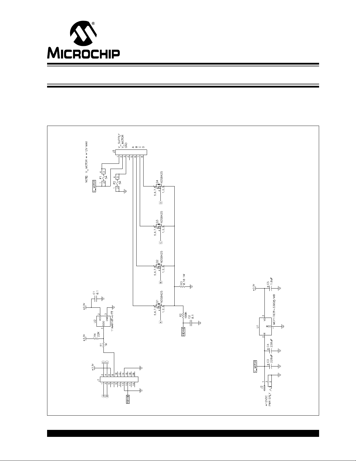
F1 LV EVALUATION PLATFORM
MOTOR CONTROL ADD-ONS
Appendix A. Board Layout and Schematics
A.1 INTRODUCTION
This appendix contains the F1 LV board layout and schematics.
FIGURE A-1: F1 UNIPOLAR STEPPER MOTOR ADD-ON (SHEET 1 OF 5)
2012 Microchip Technology Inc. DS41629A-page 49
Page 50
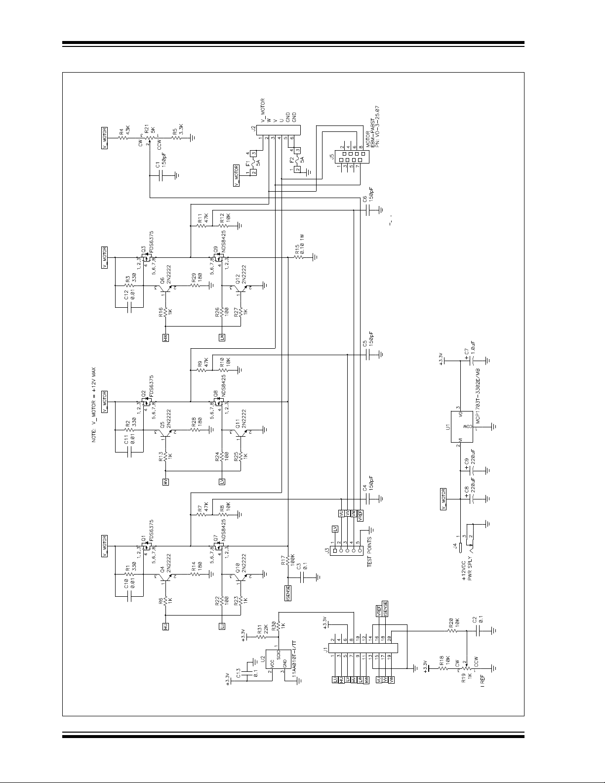
F1 LV Evaluation Platform Motor Control Add-Ons
FIGURE A-2: BLDC ADD-ON BD (SHEET 2 OF 5)
DS41629A-page 50 2012 Microchip Technology Inc.
Page 51
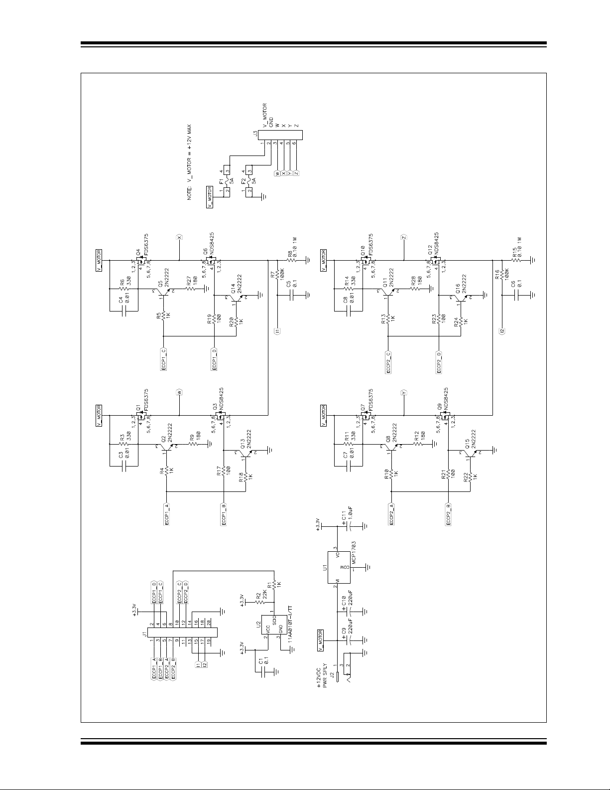
Board Layout and Schematics
FIGURE A-3: F1 BIPOLAR STEPPER MOTOR ADD-ON (SHEET 3 OF 5)
2012 Microchip Technology Inc. DS41629A-page 51
Page 52
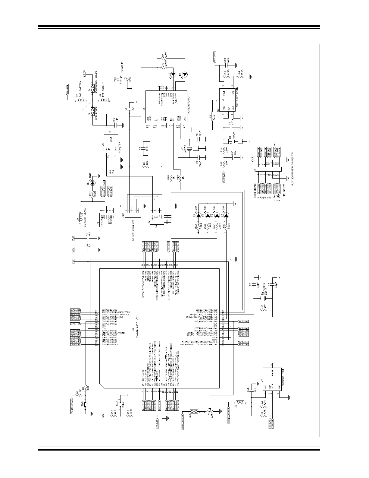
F1 LV Evaluation Platform Motor Control Add-Ons
FIGURE A-4: F1 FV EVALUATION PLATFORM (SHEET 4 OF 5)
DS41629A-page 52 2012 Microchip Technology Inc.
Page 53

Board Layout and Schematics
FIGURE A-5: F1 BDC MOTOR ADD-ON (SHEET 5 OF 5)
2012 Microchip Technology Inc. DS41629A-page 53
Page 54

F1 LV Evaluation Platform Motor Control Add-Ons
NOTES:
DS41629A-page 54 2012 Microchip Technology Inc.
Page 55

Appendix B. Conversion Factors
Commutation Period = 65536 – (Speed Control Value * 256)
RPM = 60 * Timer1 Frequency / (NumberOfPoles * BLDC Phases * Commutation Period)
TIMEBASE_SLOW_STEP = Slow Step Time (ms) *TimeBaseManager() time-tick
B.1 SYSTEM CONSTANTS
Many of the conversion factors are based on operating parameters of the PIC® microcontroller. Those parameters are determined at compile time and are assumed to be
fixed. The fixed parameters and their associated values are as follows:
TABLE B-1:
Parameter Value
OSC 32 MHz
F
System Frequency F
Timer 1 Prescale 8
Timer 1 Frequency System Frequency/Timer 1 Prescale
Timer 2 Prescale 4
Timer 2 Frequency System Frequency/Timer 2 Prescale
BLDC Phases 3
Max. Speed Request 255
F1 LV EVALUATION PLATFORM
MOTOR CONTROL ADD-ONS
OSC/4
B.2 START-UP: SPEED
The start-up commutation speed is the initial commutation period expressed as Timer1
counts. The number entered in the Speed box is the inverse (16-bit number negative)
of initial commutation period divided by 256 (upper 8 bits of a 16-bit number). The use
of the inverse can be explained as follows: Because it is natural to think of small values
as slow and large values as fast, the open-loop speed control starts at 0 and tops out
at 255. The commutation time counter, however, operates on the inverse of the Speed
Control value, because long commutation times result in slower speeds than short
commutation times. The RPM derived from the commutation period is computed as
follows:
EQUATION B-1:
B.3 SLOW STEP
The slow-step dwell time is measured in TimeBaseManager() time-ticks which are
derived from Timer0. The TimeBaseManager() sets time-elapsed flags at every 10 millisecond time-tick. The various routines monitor the TimeBaseManager() flags to determine when to perform their service. Divide the Slow-Step time by the
TimeBaseManager() time-tick to determine the TIMEBASE_SLOW_STEP count.
EQUATION B-2:
2012 Microchip Technology Inc. DS41629A-page 55
Page 56

F1 LV Evaluation Platform Motor Control Add-Ons
Request Percent = Raw Request Value * 100 / Maximum Request Value
Request Percent = Raw Request Value * 100 / 255
MOTOR_STEP_ANGLE = Degrees per step * 10
Degrees per step = MOTOR_STEP_ANGLE * 0.1
Min Duty Percent = MIN_DUTY * 100 / 255
Max Duty Percent = MAX_DUTY * 100 / 255
B.4 STEPPER RUN AND STOP PERCENTAGES
The Run and Stop thresholds in the stepper motor include files are expressed as raw
speed request numbers. The speed request is an 8-bit unsigned integer entered either
from the Analog-to-Digital conversion of the potentiometer voltage, or specified directly
from the PC controller through the serial input. The maximum speed request is the
maximum value of a byte or 255. The conversion factor to convert the raw speed
request to a percentage is 100 divided by the maximum speed request number.
EQUATION B-3:
B.5 DEGREES PER STEP
The assembler works only with integer math. Therefore, the header files specify all values as integers. In order to maintain the full resolution of floating point numbers, floating
point values are multiplied by factors of 10 so they can be expressed as integer values.
Motor step angles are multiplied by 10 to achieve the desired step angle resolution of
0.1 degree.
EQUATION B-4:
B.6 STEPPER: MIN AND MAX DUTY PERCENT
The mininum and maximum duty cycle percentages are based on the maximum duty
cycle value of 255. For all drive modes, except microstepping, the 8-bit duty cycle value
is translated to the 10 bits required for the PWM by the LinearSpeedProfile look-up
table. The MIN_DUTY and MAX_DUTY header file parameters are specified as inputs
to the look-up table. In other words, a MAX_DUTY parameter of 255 equates to 100%
duty cycle.
EQUATION B-5:
B.7 CONSTANTS DERIVED FROM STEPPER PARAMETERS
The stepper motor parameter optimization section introduced two constants not shown
in the GUI parameters. Both constants are computed from the other parameters at
compile time and saved for use during execution. In fact, the parameters that define
these two constants are not accessible during program execution. Only the constants
are necessary.
B.7.1 DUTY_SCALE Constant
The DUTY_CYCLE constant is multiplied by 256 for use in the scaling computation.
The final result of the scaling multiplication is therefore 256 times larger than needed.
This maintains the 8-bit resolution for the parameter and forgoes the need for floating
point calculations during execution. Final reduction of the multiplication is simply a matter of using the Most Significant Byte of the result. The DUTY_CYCLE constant is
defined as follows:
DS41629A-page 56 2012 Microchip Technology Inc.
Page 57

EQUATION B-7:
DUTY_CYCLE = (MAX_DUTY – MIN_DUTY + 1) * 256 / Max Speed Request
SPEED_SCALING_CONST = Timer 1 Frequency * Max Speed Request * Motor Degrees Per Step * 60 / 360 * Max RPM
SPEED_SCALING_CONST = Timer 1 Frequency * Motor Degrees Per Step * 255 / (6 * Max RPM)
Conversion Factors
EQUATION B-6:
The 256 factor in the numerator is the multiplier which scales the result up by one byte
width. Max Speed Request normalizes the constant to the speed request range. Notice
that Max Speed Request is 255, which is approximately equal to the 256 multiplier. The
difference is insignificant, so the 256 multiplier cancels out the Max Speed Request,
allowing the DUTY_CYCLE to be stored as an 8-bit integer.
B.7.2 SPEED_SCALING_CONST Constant
The SPEED_SCALING_CONST is used to convert the speed request to the number of
Timer1 counts in one commutation period. The SPEED_SCALING_CONST is a function of:
• Timer1 frequency
• Motor degrees per step
• Maximum speed request
• Maximum motor speed when the maximum drive voltage is applied
The SPEED_SCALING_CONST is stored as a 32-bit integer.
B.8 USTEP TABLE
In order to understand the microstep drive table values, you must first understand how
the PWM period duty cycle is generated: The output drive goes active at the beginning
of the PWM period, and is forced inactive part way through the period by the value of
a timer. The ratio of the active time relative to the PWM period is the duty cycle.
The PWM period is determined by the Timer2 frequency and PR2 register. Timer2
counts up to the value of PR2 then resets. The active drive period is determined by the
8-bit value in CCPR1L plus two more bits in CCP1CON. Two Least Significant bits of
Timer2 extend beyond the 8-bit Timer2 register (TMR2), and are used to compare with
the two CCP1CON bits mentioned. The CCP output drive is active from when Timer2
resets until the count reaches CCPR1L. The output drive remains inactive for the
remainder of the counts until Timer2 resets at the value of PR2.
The longest PWM period, for which there are 256 TMR2 counts, is achieved when PR2
is the maximum value. All 8 bits can be resolved for the duty cycle when PR2 is set to
the maximum. There are two additional Least Significant resolution bits in the
CCP1CON register, DCB0 and DCB1, which extend the duty cycle resolution to a maximum of 10 bits. Frequencies higher than the lowest require a PR2 value less than the
maximum. Anything less than the maximum value in PR2 will reduce the duty cycle resolution.
In our system, the PWM frequency is 16 kHz. The PR2 value to achieve this is 0x7D or
125 decimal. Actually, PR2 is set to 0x7C so that a 100% duty cycle is achieved when
0x7D is placed in the CCPR1L register. All values up to 0x7C can be expressed with 7
bits. Those 7 bits plus the two Least significant bits in the CCP1CON register yield a
9-bit duty cycle resolution. We use only the Most Significant 8 bits of the 9, because it
reduces the size and complexity of the microstepping look-up tables. Considering that
the maximum 7-bit PR2 value for 16 kHz operation is 125, then the 8-bit maximum
value (7 bits for CCPR1L and 1 bit for DCB1) is 250.
2012 Microchip Technology Inc. DS41629A-page 57
Page 58

F1 LV Evaluation Platform Motor Control Add-Ons
During microstepping, the LinearSpeedProfile look-up table is not used: The drive values go directly from the microstep table into the CCP duty cycle registers without any
additional scaling. The microstepping tables consist of pre-scaled sine wave data for
one quarter of a full cycle. The factory default scaling factor for the two types of stepper
motors is 100% for the bipolar (250 maximum), and 50% for the unipolar (125 maximum). No scaling information about the table values residing in the Platform memory
is available to the GUI, therefore the “uStep %” box is blank. You have only the option
of generating a new table based on the scaling factor entered in the “uStep %” box.
When you generate a new microstep table, then the values are immediately placed in
the Platform RAM and will be lost at the next Reset. To make the new table values
endure Resets replace the EEPROM values with the new table values by selecting the
pull-down File->RAM->EEPROM
option after creating the new table.
DS41629A-page 58 2012 Microchip Technology Inc.
Page 59

NOTES:
F1 LV Evaluation Platform Motor Control Add-Ons
2012 Microchip Technology Inc. DS41629A-page 59
Page 60

Worldwide Sales and Service
AMERICAS
Corporate Office
2355 West Chandler Blvd.
Chandler, AZ 85224-6199
Tel: 480-792-7200
Fax: 480-792-7277
Technical Support:
http://www.microchip.com/
support
Web Address:
www.microchip.com
Atlanta
Duluth, GA
Tel: 678-957-9614
Fax: 678-957-1455
Boston
Westborough, MA
Tel: 774-760-0087
Fax: 774-760-0088
Chicago
Itasca, IL
Tel: 630-285-0071
Fax: 630-285-0075
Cleveland
Independence, OH
Tel: 216-447-0464
Fax: 216-447-0643
Dallas
Addison, TX
Tel: 972-818-7423
Fax: 972-818-2924
Detroit
Farmington Hills, MI
Tel: 248-538-2250
Fax: 248-538-2260
Indianapolis
Noblesville, IN
Tel: 317-773-8323
Fax: 317-773-5453
Los Angeles
Mission Viejo, CA
Tel: 949-462-9523
Fax: 949-462-9608
Santa Clara
Santa Clara, CA
Tel: 408-961-6444
Fax: 408-961-6445
Toronto
Mississauga, Ontario,
Canada
Tel: 905-673-0699
Fax: 905-673-6509
ASIA/PACIFIC
Asia Pacific Office
Suites 3707-14, 37th Floor
Tower 6, The Gateway
Harbour City, Kowloon
Hong Kong
Tel: 852-2401-1200
Fax: 852-2401-3431
Australia - Sydney
Tel: 61-2-9868-6733
Fax: 61-2-9868-6755
China - Beijing
Tel: 86-10-8569-7000
Fax: 86-10-8528-2104
China - Chengdu
Tel: 86-28-8665-5511
Fax: 86-28-8665-7889
China - Chongqing
Tel: 86-23-8980-9588
Fax: 86-23-8980-9500
China - Hangzhou
Tel: 86-571-2819-3187
Fax: 86-571-2819-3189
China - Hong Kong SAR
Tel: 852-2401-1200
Fax: 852-2401-3431
China - Nanjing
Tel: 86-25-8473-2460
Fax: 86-25-8473-2470
China - Qingdao
Tel: 86-532-8502-7355
Fax: 86-532-8502-7205
China - Shanghai
Tel: 86-21-5407-5533
Fax: 86-21-5407-5066
China - Shenyang
Tel: 86-24-2334-2829
Fax: 86-24-2334-2393
China - Shenzhen
Tel: 86-755-8203-2660
Fax: 86-755-8203-1760
China - Wuhan
Tel: 86-27-5980-5300
Fax: 86-27-5980-5118
China - Xian
Tel: 86-29-8833-7252
Fax: 86-29-8833-7256
China - Xiamen
Tel: 86-592-2388138
Fax: 86-592-2388130
China - Zhuhai
Tel: 86-756-3210040
Fax: 86-756-3210049
ASIA/PACIFIC
India - Bangalore
Tel: 91-80-3090-4444
Fax: 91-80-3090-4123
India - New Delhi
Tel: 91-11-4160-8631
Fax: 91-11-4160-8632
India - Pune
Tel: 91-20-2566-1512
Fax: 91-20-2566-1513
Japan - Osaka
Tel: 81-66-152-7160
Fax: 81-66-152-9310
Japan - Yokohama
Tel: 81-45-471- 6166
Fax: 81-45-471-6122
Korea - Daegu
Tel: 82-53-744-4301
Fax: 82-53-744-4302
Korea - Seoul
Tel: 82-2-554-7200
Fax: 82-2-558-5932 or
82-2-558-5934
Malaysia - Kuala Lumpur
Tel: 60-3-6201-9857
Fax: 60-3-6201-9859
Malaysia - Penang
Tel: 60-4-227-8870
Fax: 60-4-227-4068
Philippines - Manila
Tel: 63-2-634-9065
Fax: 63-2-634-9069
Singapore
Tel: 65-6334-8870
Fax: 65-6334-8850
Taiwan - Hsin Chu
Tel: 886-3-5778-366
Fax: 886-3-5770-955
Taiwan - Kaohsiung
Tel: 886-7-536-4818
Fax: 886-7-330-9305
Taiwan - Taipei
Tel: 886-2-2500-6610
Fax: 886-2-2508-0102
Thailand - Bangkok
Tel: 66-2-694-1351
Fax: 66-2-694-1350
EUROPE
Austria - Wels
Tel: 43-7242-2244-39
Fax: 43-7242-2244-393
Denmark - Copenhagen
Tel: 45-4450-2828
Fax: 45-4485-2829
France - Paris
Tel: 33-1-69-53-63-20
Fax: 33-1-69-30-90-79
Germany - Munich
Tel: 49-89-627-144-0
Fax: 49-89-627-144-44
Italy - Milan
Tel: 39-0331-742611
Fax: 39-0331-466781
Netherlands - Drunen
Tel: 31-416-690399
Fax: 31-416-690340
Spain - Madrid
Tel: 34-91-708-08-90
Fax: 34-91-708-08-91
UK - Wokingham
Tel: 44-118-921-5869
Fax: 44-118-921-5820
11/29/11
DS41629A-page 60 2012 Microchip Technology Inc.
 Loading...