

Page 1
Explorer 8 Development Board
User’s Guide
2015 Microchip Technology Inc. DS40001812A
Page 2

Note the following details of the code protection feature on Microchip devices:
YSTEM
CERTIFIED BY DNV
== ISO/TS 16949 ==
• Microchip products meet the specification contained in their particular Microchip Data Sheet.
• Microchip believes that its family of products is one of the most secure families of its kind on the market today, when used in the
intended manner and under normal conditions.
• There are dishonest and possibly illegal methods used to breach the code protection feature. All of these methods, to our
knowledge, require using the Microchip products in a manner outside the operating specifications contained in Microchip’s Data
Sheets. Most likely, the person doing so is engaged in theft of intellectual property.
• Microchip is willing to work with the customer who is concerned about the integrity of their code.
• Neither Microchip nor any other semiconductor manufacturer can guarantee the security of their code. Code protection does not
mean that we are guaranteeing the product as “unbreakable.”
Code protection is constantly evolving. We at Microchip are committed to continuously improving the code protection features of our
products. Attempts to break Microchip’s code protection feature may be a violation of the Digital Millennium Copyright Act. If such acts
allow unauthorized access to your software or other copyrighted work, you may have a right to sue for relief under that Act.
Information contained in this publication regarding device
applications and the like is provided only for your convenience
and may be superseded by updates. It is your responsibility to
ensure that your application meets with your specifications.
MICROCHIP MAKES NO REPRESENTATIONS OR
WARRANTIES OF ANY KIND WHETHER EXPRESS OR
IMPLIED, WRITTEN OR ORAL, STATUTORY OR
OTHERWISE, RELATED TO THE INFORMATION,
INCLUDING BUT NOT LIMITED TO ITS CONDITION,
QUALITY, PERFORMANCE, MERCHANTABILITY OR
FITNESS FOR PURPOSE. Microchip disclaims all liability
arising from this information and its use. Use of Microchip
devices in life support and/or safety applications is entirely at
the buyer’s risk, and the buyer agrees to defend, indemnify and
hold harmless Microchip from any and all damages, claims,
suits, or expenses resulting from such use. No licenses are
conveyed, implicitly or otherwise, under any Microchip
intellectual property rights unless otherwise stated.
Trademarks
The Microchip name and logo, the Microchip logo, dsPIC,
FlashFlex, flexPWR, JukeBlox, K
LANCheck, MediaLB, MOST, MOST logo, MPLAB,
OptoLyzer, PIC, PICSTART, PIC
SST, SST Logo, SuperFlash and UNI/O are registered
trademarks of Microchip Technology Incorporated in the
U.S.A. and other countries.
The Embedded Control Solutions Company and mTouch are
registered trademarks of Microchip Technology Incorporated
in the U.S.A.
Analog-for-the-Digital Age, BodyCom, chipKIT, chipKIT logo,
CodeGuard, dsPICDEM, dsPICDEM.net, ECAN, In-Circuit
Serial Programming, ICSP, Inter-Chip Connectivity, KleerNet,
KleerNet logo, MiWi, MPASM, MPF, MPLAB Certified logo,
MPLIB, MPLINK, MultiTRAK, NetDetach, Omniscient Code
Generation, PICDEM, PICDEM.net, PICkit, PICtail,
RightTouch logo, REAL ICE, SQI, Serial Quad I/O, Total
Endurance, TSHARC, USBCheck, VariSense, ViewSpan,
WiperLock, Wireless DNA, and ZENA are trademarks of
Microchip Technology Incorporated in the U.S.A. and other
countries.
SQTP is a service mark of Microchip Technology Incorporated
in the U.S.A.
Silicon Storage Technology is a registered trademark of
Microchip Technology Inc. in other countries.
GestIC is a registered trademark of Microchip Technology
Germany II GmbH & Co. KG, a subsidiary of Microchip
Technology Inc., in other countries.
All other trademarks mentioned herein are property of their
respective companies.
© 2015, Microchip Technology Incorporated, Printed in the
U.S.A., All Rights Reserved.
ISBN: 978-1-63277-689-1
EELOQ, KEELOQ logo, Kleer,
32
logo, RightTouch, SpyNIC,
QUALITY MANAGEMENT S
DS40001812A-page 2 2015 Microchip Technology Inc.
Microchip received ISO/TS-16949:2009 certification for its worldwide
headquarters, design and wafer fabrication facilities in Chandler and
Tempe, Arizona; Gresham, Oregon and design centers in California
and India. The Company’s quality system processes and procedures
are for its PIC
devices, Serial EEPROMs, microperipherals, nonvolatile memory and
analog products. In addition, Microchip’s quality system for the design
and manufacture of development systems is ISO 9001:2000 certified.
®
MCUs and dsPIC® DSCs, KEELOQ
®
code hopping
Page 3

EXPLORER 8 DEVELOPMENT BOARD
USER’S GUIDE
Table of Contents
Preface ...........................................................................................................................5
Chapter 1. Overview
1.1 Introduction ................................................................................................... 11
1.2 Development Kit Contents ............................................................................ 11
1.3 Explorer 8 Development Board .................................................................... 12
1.4 On-Board Jumper Configurations ................................................................. 13
1.5 Sample Devices ........................................................................................... 17
1.6 Sample Programs ......................................................................................... 17
Chapter 2. Getting Started
2.1 Explorer 8 with Pre-Programmed Device ..................................................... 19
2.2 Board with PIM Attached Devices ................................................................ 21
2.3 Programming the Microcontrollers ............................................................... 21
2.3.1 Programming Requirements ...................................................................... 21
2.3.2 Opening the Program in MPLAB
2.3.3 Programming the Microcontroller .............................................................. 23
2.4 Connecting to Host PC for USB Communication ......................................... 24
2.4.1 USB-to-UART Interface ............................................................................. 25
2.4.2 USB-to-I2C Interface ................................................................................. 25
2.5 Powering the Board ...................................................................................... 26
2.5.1 External 9V Power Supply ......................................................................... 26
2.5.2 USB Power ................................................................................................ 26
2.6 Selecting Vdd Values ................................................................................... 27
2.6.1 Varying the Device Voltage ....................................................................... 27
2.6.2 Calculating other Vdd Values .................................................................... 27
®
X IDE ................................................... 22
Chapter 3. Tutorial Program
3.1 Tutorial Program Operation .......................................................................... 29
3.2 Source Code and Data Sheets ..................................................................... 31
Appendix A. Hardware Details
A.1 Hardware Elements ..................................................................................... 33
A.1.1 Processor Sockets .................................................................................... 33
A.1.2 Display ...................................................................................................... 33
A.1.3 Power Supply ............................................................................................ 33
A.1.4 Micro USB Port ......................................................................................... 34
A.1.5 Switches .................................................................................................... 34
A.1.6 Oscillator Options ...................................................................................... 34
A.1.7 Analog Input (Potentiometer) .................................................................... 34
A.1.8 ICD Connector .......................................................................................... 34
A.1.9 PICkit
A.1.10 PICtail
A.1.11 mikroBUS
2015 Microchip Technology Inc. DS40001812A-page 3
™
Connector .................................................................................... 34
™
and PICtail Plus Expansion Connectors ................................... 35
™
Connectors .......................................................................... 35
Page 4

Explorer 8 Development Board User’s Guide
A.1.12 Pmod™ Connectors .................................................................................35
A.1.13 Configurable In-line Connector ................................................................35
A.1.14 LCD .........................................................................................................35
A.1.15 Sample Devices .......................................................................................36
A.2 Board Layout and Schematics ..................................................................... 37
Worldwide Sales and Service .....................................................................................41
DS40001812A-page 4 2015 Microchip Technology Inc.
Page 5

EXPLORER 8 DEVELOPMENT BOARD
USER’S GUIDE
Preface
NOTICE TO CUSTOMERS
All documentation becomes dated, and this manual is no exception. Microchip tools and
documentation are constantly evolving to meet customer needs, so some actual dialogs
and/or tool descriptions may differ from those in this document. Please refer to our web site
(www.microchip.com) to obtain the latest documentation available.
Documents are identified with a “DS” number. This number is located on the bottom of each
page, in front of the p age number. The numbering convention for the DS number is
“DSXXXXXXXXA”, where “XXXXXXXX” is the document number and “A” is the revision level
of the document.
For the most up-to-date information on development tools, see the MPLAB
Select the Help menu, and then Topics to open a list of available online help files.
INTRODUCTION
®
IDE online help.
This chapter contains general information that will be useful to know before using the
Explorer 8 Development Board. Items discussed in this chapter include:
• Document Layout
• Conventions Used in this Guide
• Warranty Registration
• Recommended Reading
• The Microchip Web Site
• Development Systems Customer Change Notification Service
• Customer Support
• Document Revision History
DOCUMENT LAYOUT
This document describes how to use the Explorer 8 Development Board as a tool to
emulate and debug firmware on a target board. The document is organized as follows:
• Chapter 1. Overview
• Chapter 2. Getting Started
• Chapter 3. Tutorial Program
• Appendix A. Hardware Details
2015 Microchip Technology Inc. DS40001812A-page 5
Page 6
Explorer 8 Development Board User’s Guide
CONVENTIONS USED IN THIS GUIDE
This manual uses the following documentation conventions:
DOCUMENT CONVENTIONS
Description Represents Examples
Arial font:
Italic characters Referenced books MPLAB
Emphasized text ...is the only compiler...
Initial caps A window the Output window
A dialog the Settings dialog
A menu selection select Enable Programmer
Quotes A field name in a window or
dialog
Underlined, italic text with
right angle bracket
Bold characters A dialog button Click OK
N‘Rnnnn A number in verilog format,
Text in angle brackets < > A key on the keyboard Press <Enter>, <F1>
Courier New font:
Plain Courier New Sample source code #define START
Italic Courier New A variable argument file.o, where file can be
Square brackets [ ] Optional arguments mcc18 [options] file
Curly brackets and pipe
character: { | }
Ellipses... Replaces repeated text var_name [,
A menu path File>Save
A tab Click the Power tab
where N is the total number of
digits, R is the radix and n is a
digit.
Filenames autoexec.bat
File paths c:\mcc18\h
Keywords _asm, _endasm, static
Command-line options -Opa+, -Opa-
Bit values 0, 1
Constants 0xFF, ‘A’
Choice of mutually exclusive
arguments; an OR selection
Represents code supplied by
user
“Save project before build”
4‘b0010, 2‘hF1
any valid filename
[options]
errorlevel {0|1}
var_name...]
void main (void)
{ ...
}
®
IDE User’s Guide
DS40001812A-page 6 2015 Microchip Technology Inc.
Page 7

WARRANTY REGISTRATION
Please complete the enclosed Warranty Registration Card and mail it promptly.
Sending in the Warranty Registration Card entitles users to receive new product
updates. Interim software releases are available at the Microchip web site.
RECOMMENDED READING
This user’s guide describes how to use the Explorer 8 Development Board. The
following documents are available and recommended as supplemental reference
resources.
Explorer 8 Development Board Layout and Schematic Quick Start Guide
(DS40001805)
This quick start guide provides a brief overview on the Explorer 8 Development Board’s
functionalities, features and capabilities.
MPLAB
This document provides all the necessary information on the MPLAB ICD 3 In-Circuit
Debugger’s operation, installation, general setup and tutorial details. The MPLAB ICD
3 is a cost-effective, high-speed hardware debugger/programmer developed by
Microchip for PIC
MPLAB
(DS50002085)
This user’s guide describes how to use the MPLAB REAL ICE In-Circuit Emulator as a
development tool to emulate and debug firmware on a target board, as well as how to
program devices. It provides details on the emulator’s operation, features,
troubleshooting, software, hardware reference and emulator accessories.
PICkit™ 3 In-Circuit Debugger/Programmer User’s Guide for MPLAB
(DS52116)
This user’s guide describes the PICkit 3 In-Circuit Debugger/Programmer’s operation,
usage, troubleshooting methods and hardware specifications. The PICkit 3 can be
implemented as a debugger or development programmer for Microchip PIC MCUs and
DSCs that are based on In-Circuit Serial Programming™ (ICSP™) and Enhanced
ICSP 2-wire serial interfaces.
®
ICD 3 In-Circuit Debugger User’s Guide (DS51766)
®
REAL ICE™ In-Circuit Emulator User’s Guide for MPLAB X IDE
®
microcontrollers and Digital Signal Controllers (DSCs).
Preface
®
X IDE
2015 Microchip Technology Inc. DS40001812A-page 7
Page 8

Explorer 8 Development Board User’s Guide
THE MICROCHI P WEB SITE
Microchip provides online support via our web site at www.microchip.com. This web
site is used as a means to make files and information easily available to customers.
Accessible by using your favorite Internet browser, the web site contains the following
information:
• Product Support – Data sheets and errata, application notes and sample
programs, design resources, user’s guides and hardware support documents,
latest software releases and archived software.
• General Technical Support – Frequently Asked Questions (FAQs), technical
support requests, online discussion groups, Microchip consultant program
member listing.
• Business of Microchip – Product selector and ordering guides, latest Microchip
press releases, listing of seminars and events, listings of Microchip sales offices,
distributors and factory representatives.
DEVELOPMENT SYSTEMS CUSTOMER CHANGE NOTIFICATION SERVICE
Microchip’s customer notification service helps keep customers current on Microchip
products. Subscribers will receive e-mail notification whenever there are changes,
updates, revisions or errata related to a specified product family or development tool of
interest.
To register, access the Microchip web site at www.microchip.com, click on Customer
Change Notification and follow the registration instructions.
The Development Systems product group categories are:
• Compilers – The latest information on Microchip C compilers, assemblers, linkers
and other language tools. These include the MPLAB XC Compilers that support
all 8-, 16- and 32-bit PIC MCUs and dsPIC
• Emulators – The latest information on Microchip in-circuit emulators. This
includes the MPLAB REAL ICE In-Circuit Emulator.
• In-Circuit Debuggers – The latest information on the Microchip in-circuit
debuggers. This includes the MPLAB ICD 3 In-Circuit Debugger and the PICkit 3
In-Circuit Debugger.
• MPLAB
Integrated Development Environment for development systems tools which can
be run on Windows
• Programmers – The latest information on Microchip programmers. These include
the device (production) programmers MPLAB REAL ICE in-circuit emulator and
MPLAB ICD 3 in-circuit debugger, and the development (non-production)
programmer PICkit 3.
®
X IDE – The latest information on Microchip MPLAB X IDE, the
®
, Mac OS® and LINUX® operating systems.
®
DSCs.
DS40001812A-page 8 2015 Microchip Technology Inc.
Page 9

CUSTOMER SUPPORT
Users of Microchip products can receive assistance through several channels:
• Distributor or Representative
• Local Sales Office
• Field Application Engineer (FAE)
• Technical Support
Customers should contact their distributor, representative or field application engineer
(FAE) for support. Local sales offices are also available to help customers.
Technical support is available through the web site at:
http://www.microchip.com/support.
DOCUMENT REVISION HISTORY
Revision A (August, 2015)
Initial release of the document.
Preface
2015 Microchip Technology Inc. DS40001812A-page 9
Page 10

Explorer 8 Development Board User’s Guide
NOTES:
DS40001812A-page 10 2015 Microchip Technology Inc.
Page 11

1.1 INTRODUCTION
EXPLORER 8 DEVELOPMENT BOARD
USER’S GUIDE
Chapter 1. Overview
The Explorer 8 Development Board is one of the latest development boards for
evaluating and demonstrating the capabilities and features of Microchip’s 8-bit PIC
MCUs. This board supports 8/14/20/28/40-pin DIP and 44/64/80-pin PIM-mounted PIC
MCUs.
This board is fully populated with two fixed and one variable power supply, a 16x2
Character LCD module, a pair of mikroBUS™ Click™ board headers to accommodate
a variety of plug-in modules, a pair of Digilent Pmod™ connectors, an in-line
completely configurable connector, PICtail™ connectors and a USB-to-serial/I
converter. The Explorer 8 is fully compatible with the MPLAB
MPLAB X v3.00 or later.
1.2 DEVELOPMENT KI T CON TEN TS
The Explorer 8 Development Board comes with the following:
• Explorer 8 Development Board (DM160228)
• Pre-programmed PIC16F1719
• Micro USB cable
If the kit is missing any of these parts, please contact the nearest Microchip sales office
listed in the back of this publication.
The MPLAB X Integrated Development Environment (IDE) is a free, integrated
software tool set for application development and debugging. Compilers and other
board-compatible software and hardware tools can be purchased.
To download the MPLAB X IDE software and documentation, or get information on the
other tools, visit www.microchip.com/devtools.
2
®
Code Configurator and
C
®
2015 Microchip Technology Inc. DS40001812A-page 11
Page 12

Explorer 8 Development Board User’s Guide
1.3 EXPLORER 8 DEVELOPMENT BOARD
The Explorer 8 Development Board has the following hardware features. Each
feature’s number corresponds to the number in Figure 1-1, showing the feature’s
location on the board:
2
1. MCP2221 USB-to-UART/I
2. 16x2 Character LCD (LCD1)
3. MCP23S17 I/O Expander for LCD Interface (U4)
4. Eight blue LEDs (D1 to D8).
5. Male header pins for attaching Plug-in-Modules (U1A)
6. Socket for attaching 40-pin PIC MCUs (J8)
7. Socket for attaching 28-pin PIC MCUs (J13)
8. Socket for attaching 8/14/20-pin PIC MCUs (J10)
9. mikroBUS headers for attaching mikroBUS compatible boards (J32 and J35)
10. Two push button switches for external stimulus (S1 and S2)
11. PICtail Expansion Connectors for PICtail Daughter Boards (J3, J5, J11 and J28)
12. PICtail Plus Card Edge Modular Expansion Connectors for PICtail Plus Daughter
Boards (J19)
13. Test Points for 5.0V (TP1 and TP7), 3.3V (TP6) and V_VAR (TP5). V_VAR is the
variable voltage and is equal to the device V
14. 20-pin in-line expansion connector (J33)
15. 8 MHz crystal for device external oscillator (Y1)
16. Digilent Pmod compatible connectors (J17 and J20)
17. 10 kΩ Potentiometer for analog inputs (R25)
18. Variable Power Indicator LED (D9)
19. 3.3V Power Indicator (LD2)
20. 5.0V Power Indicator (LD1)
21. 5.0V (U5), 3.3V (U1) and Variable (U2) power supplies
22. Barrel connector for 9V DC Supply (J1)
23. RJ11 connector for ICSP programming/debugging using REAL ICE and ICD 3
(J26)
24. 6-pin male header for ICSP programming/debugging using PICkit 3 (J12)
25. Push button switch on MCLR
26. Micro USB socket for USB communication and/or USB power (J18)
C serial converter (U3)
DD and its associated logic
for external Reset (S3)
DS40001812A-page 12 2015 Microchip Technology Inc.
Page 13
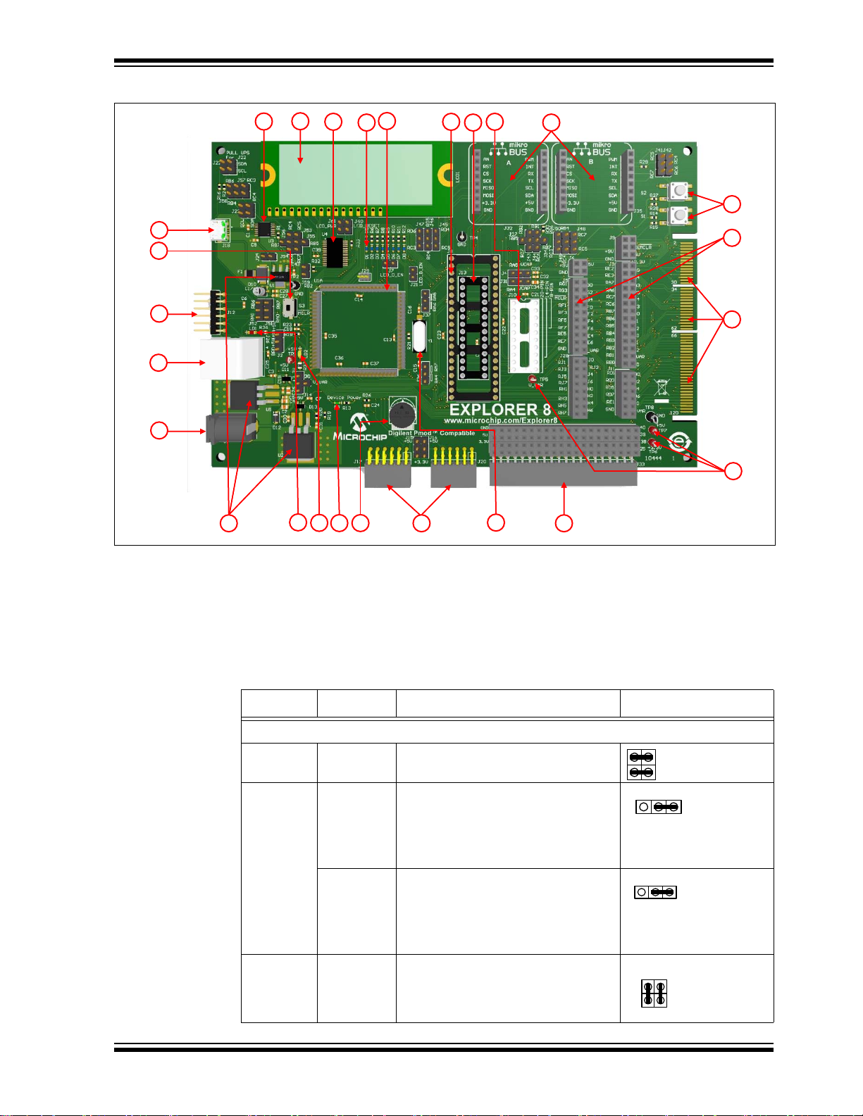
FIGURE 1-1: EXPLORER 8 DEVELOPMENT BOARD
1
2
3
4
6
7
8
9
10
11
12
13
14
15
16
17 18
19
20
22
23
24
21
25
26
5
SDA
SCL
RC3RB6
RC4RB4
SDASCL
Overview
1.4 ON-BOARD JUMPER CONFIGURATIONS
The Explorer 8 Development Board allows the user to connect or disconnect
components from PIC
associated jumpers. Table 1-1 and Figure 1-2 provide details and examples for these
connections.
TABLE 1-1: ON-BOARD JUMPERS DESCRIPTION AND SAMPLE
Label Jumper/s Description Configuration
MCU Interface to MCP2221 USB-to-I2C/UART Converter
1 J22 Pulls up the configured I2C SCL pin
2 J57 Connects the microcontroller I
J58 Connects the microcontroller I
3 J23 Connects the microcontroller I
MCU pins or from other on-board components through
CONFIGURATION
(see J57) and SDA pin (see J58).
pin to the MCP2221 SCL pin (see
Label 3).
E.g. RC3 is configured as the
microcontroller I
pin to the MCP2221 SDA pin (see
Label 3).
E.g. RC4 is configured as the
microcontroller I
and SDA pins to the MCP2221 SCL
and SDA pins, respectively.
2
C SCL pin.
2
C SDA pin.
(1)
2
C SCL
2
C SDA
2
C SCL
2015 Microchip Technology Inc. DS40001812A-page 13
Page 14

Explorer 8 Development Board User’s Guide
RC7
RC5
RB5
J55
J53
RC6
RC4
RB7
J56
J54
LCD_RESET
J59
LED_D_EN
LED_B_EN
RC5
RD4
RD5
RC4
RD6
RC3
RC7
RG2
RB5
J27
J43
RC6
RG1
J34
J44
RB7
TABLE 1-1: ON-BOARD JUMPERS DESCRIPTION AND SAMPLE
CONFIGURATION (CONTINUED)
Label Jumper/s Description Configuration
4 J53, J55 Connects the microcontroller UART
RX pin to the MCP2221 TX pin.
E.g. RC7 is configured as the
microcontroller RX pin.
J54, J56 Connects the microcontroller UART
TX pin to the MCP2221 RX pin.
E.g. RC6 is configured as the
microcontroller TX pin.
MCU Interface to MCP23S17 I/O Expander
5 J60 Connects RB5 to the MCP23S17 I/O
Expander RESET pin.
J59 Connects RA2 to the MCP23S17 I/O
Expander Chip Select (CS) pin.
MCU Interface to the LEDs
(1)
6 J7 Connects LEDs D1 to D4 cathodes to
ground to provide a continuous LED
current path.
(1)
J21 Connects LEDs D5 to D8 cathodes to
ground to provide a continuous LED
current path.
MCU Interface to J32 mikroBUS™
(1)
7 J45 Connects the microcontroller SDO pin
to the J32 mikroBUS MOSI (SPI
Master Output Slave Input) pin.
E.g. RC5 is configured as the
microcontroller SDO pin.
J46 Connects the microcontroller SDI pin
to the J32 mikroBUS MISO (SPI
Master Input Slave Output) pin
E.g. RC4 is configured as the
microcontroller SDI pin.
J47 Connects the microcontroller SCK pin
to the J32 mikroBUS SCK (SPI Clock)
pin.
E.g. RC3 is configured as the
microcontroller SCK pin.
8 J27, J43 Connects the microcontroller RX pin to
the J32 mikroBUS UART RX pin.
E.g. RC7 is configured as the
microcontroller RX pin.
J34, J44 Connects the microcontroller TX pin to
the J32 mikroBUS UART TX pin.
E.g. RC6 is configured as the
microcontroller TX pin.
DS40001812A-page 14 2015 Microchip Technology Inc.
Page 15

Overview
RC7
RC5
RB4
RC4
RB6
RC3
RC5
RC7
RC4
RC6
VCAPRA5
J4
VCAPRA4
J31
RA5
RA6
RA7
RA4
+5V+5V
+3.3V
J15 J16
+5V
+3.3V
J30
J14
V_VAR
TABLE 1-1: ON-BOARD JUMPERS DESCRIPTION AND SAMPLE
CONFIGURATION (CONTINUED)
Label Jumper/s Description Configuration
MCU Interface to J35 mikroBUS
9 J48 Connects the microcontroller SDO pin
J49 Connects the microcontroller SDI pin
J50 Connects the microcontroller SCK pin
10 J41 Connects the microcontroller RX pin to
(1)
to the J35 mikroBUS MOSI (SPI
Master Output Slave Input) pin.
E.g. RC5 is configured as the
microcontroller SDO pin.
to the J35 mikroBUS MISO (SPI
Master Input Slave Output) pin.
E.g. RC4 is configured as the
microcontroller SDI pin.
to the J35 mikroBUS SCK (SPI Clock)
pin.
E.g. RC3 is configured as the
microcontroller SCK pin.
the J35 mikroBUS UART RX pin.
E.g. RC7 is configured as the
microcontroller RX pin.
J42 Connects the microcontroller TX pin to
the J35 mikroBUS UART TX pin.
E.g. RC6 is configured as the
microcontroller TX pin.
Other Connections and Interfaces
(1)
11 J4, J31 Connections depend whether RA5
and RA4 are configured as an I/O port
or as a VCAP pin.
E.g. RA5 is configured as an I/O port
while RA4 as a VCAP pin.
12 J37 Selects whether RA6 or the RA5 pin
be connected to the external 8 MHz
crystal (Y1).
E.g. The 8 MHz crystal is connected to
the MCU OSC2/RA5 pin.
13 J36 Selects whether RA7 or the RA4 pin
be connected to the external 8 MHz
crystal (Y1).
E.g. The 8 MHz crystal is connected to
the MCU OSC1/RA7 pin.
14 J15, J16 Option to power the Digilent Pmod
with 3.3V or 5V.
E.g. J17 Pmod
while J20 Pmod
is supplied with 5V
is supplied with 3.3V
15 J14, J30 Selects either 3.3V, 5.0V or a variable
voltage for the board’s supply
E.g. The board is supplied with 5V.
2015 Microchip Technology Inc. DS40001812A-page 15
Page 16

Explorer 8 Development Board User’s Guide
USB
+5V
BRD
+5V
RB7
J52 J51
RA0
RB6
RA1
LCD_PWR
J24
1 2
3 4
5
6 7 8
9
10
11
12
1314
16
17
18
19
15
TABLE 1-1: ON-BOARD JUMPERS DESCRIPTION AND SAMPLE
CONFIGURATION (CONTINUED)
Label Jumper/s Description Configuration
16 J2 Selects whether to supply 5V power to
the board via USB or the output of the
5V regulator.
E.g. The board is USB-powered.
17 J51, J52 Connects the PGD and PGC pins of
the PICkit™ 3, ICD 3 or REAL ICE™
to the PIC
ICSPCLK, respectively for ICSP™
programming
®
MCU ICSPDAT and
18 J61 Connects the LCD V
DD pin to +5V
supply.
19 J24 To supply a regulated 3.3V output.
Note 1: Sample configurations only. Jumpers should always be disconnected for unused
interfaces and devices.
FIGURE 1-2: EXPLORER 8 DEVELOPMENT BOARD JUMPER LOCATIONS
DS40001812A-page 16 2015 Microchip Technology Inc.
Page 17

1.5 SAMPLE DEVICES
The Explorer 8 Development Board comes with a 40-pin PIC16F1719.
1.6 SAMPLE PROGRAMS
The Explorer 8 Development Board demonstration program can be downloaded from
the Microchip web site (www.microchip.com/explorer8). This Demo Code can be used
with the included sample device and with a REAL ICE (In-Circuit Emulator), MPLAB
ICD 3 (programmer/debugger) or with a PICkit 3 (programmer/debugger).The Demo
code was developed using the MPLAB Code Configurator (MCC). For more
information on MCC, visit www.microchip.com/mcc.
For a complete list of available sample programs, schematics and additional collateral
for the Explorer 8 Development Board, visit www.microchip.com/explorer8.
Overview
2015 Microchip Technology Inc. DS40001812A-page 17
Page 18

Explorer 8 Development Board User’s Guide
NOTES:
DS40001812A-page 18 2015 Microchip Technology Inc.
Page 19

EXPLORER 8 DEVELOPMENT BOARD
USB
+5V
BRD
+5V
RA5
VCAP
LED_D_EN
+3.3V
+5V
LED_B_EN
RA7
RA4
Chapter 2. Getting Started
The Explorer 8 Demo Board is very flexible and may be used in a variety of ways. This
section provides the different configurations of the board, and the required tools and
equipment for each of them.
2.1 EXPLORER 8 WITH PRE-PROGRAMMED DEVICE
Several features of the Explorer 8 Demo Board can be demonstrated immediately by
following the steps listed below:
1. Place the pre-programmed PIC16F1719 on the 40-pin socket of the Explorer 8
Development Board.
2. Ensure that the jumpers are on their proper configuration as shown in Tab le 2- 1.
See Section 1.4 “On-Board Jumper Configurations” for jumper description
and location.
Note: The table contains only a list of jumpers that are required to be setup for
proper demonstration of the Explorer 8 Development Board using the
pre-programmed device. Jumpers not listed in the table will have no effect
on the demo program.
USER’S GUIDE
TABLE 2-1: JUMPER SETUP USING THE PRE-PROGRAMMED DEVICE
Jumper/s Description Configuration
J2 Power the board via USB
J4 Use RA5 as an I/O pin
J7 Use LEDs D4 through D1
J14 Use +5.0V Supply
J21 Use LEDs D8 through D5
J36 Connect the 8 MHz Crystal to the device OSC1
pin to function as primary oscillator
2015 Microchip Technology Inc. DS40001812A-page 19
Page 20

Explorer 8 Development Board User’s Guide
RA5
RA6
RB7
RA0
RB6
RA1
RC4
RC6
J59
LCD_RESET
LCD_PWR
TABLE 2-1: JUMPER SETUP USING THE PRE-PROGRAMMED DEVICE
Jumper/s Description Configuration
J37 Connect the 8 MHz Crystal to the device OSC2
pin to function as primary oscillator
J51 For ICSP™ programming, connect the device to
the PGD pin of PICkit™ 3, ICD 3 or REAL ICE™
J52 For ICSP programming, connect the device to
the PGC pin of PICkit™ 3, ICD 3 or REAL ICE™
J54 For USB-to-UART communication
J59 To send data to the LCD
J60 To reset the MCP23S17 I/O Expander
J61 Power the LCD module
3. Apply power to the Explorer 8 Development Board using the Micro USB cable
that comes with the kit. See Section 2.6 “Selecting Vdd Values”.
The device can now be demonstrated using the tutorial program. See
Section 3.1 “Tutorial Program Operation”.
DS40001812A-page 20 2015 Microchip Technology Inc.
Page 21

2.2 BOARD WITH PIM ATTACHED DEVICES
The Explorer 8 Development Board can also be used to demonstrate PIM-mounted
8-bit PIC microcontrollers. A Plug-in-Module (PIM) enables the attachment of
44/64/80-pin devices to the board.
To attach a PIM, simply seat the PIM in the 84-pin, elevated male connectors as shown
in Figure 2-1.
FIGURE 2-1: 84-PIN HEADER FOR PLUG-IN-MODULE (PIM)
Make sure that the device mounted on the PIM is supplied with the appropriate voltage.
See Section 2.6 “Selecting Vdd Values” and Section 2.6.2 “Calculating other Vdd
Values” for supplies other than 5V and 3.3V.
Some PIMs also enable the board’s 5V output to be automatically reset to 3.3V.
For a list of microcontroller-compatible PIMs, go to www.microchip.com.
Getting Started
2.3 PROGRAMMING THE MICROCONTROLLERS
The Explorer 8 Development Board supports the ability to program a microcontroller
through multiple options.
This section discusses:
• Programming Requirements
• Opening the Program in MPLAB X IDE
• Programming the Microcontroller Using ICD 3, REAL ICE and PICkit 3
2.3.1 Programming Requirements
To reprogram a sample device, the following are required:
• Program source code – The sample code is pre-loaded on the device, but user
source code can be substituted. If this is done, the sample program can be
restored by downloading the MPLAB X project file available at the Microchip web
site.
• An assembler or compiler – The source code must be assembled or compiled
into a hex file before it can be programmed into the device.
• A programmer – Once the code is in the hex file format, this device programs the
microcontroller’s Flash memory. If the code protection bit(s) have not been
programmed, the on-chip program memory can be read out for verification
purposes.
2015 Microchip Technology Inc. DS40001812A-page 21
Page 22

Explorer 8 Development Board User’s Guide
In meeting these requirements, the following items are to be taken into consideration:
• Code development and debugging – The free MPLAB X IDE software
development tool includes a debugger and several other software tools as well as
a unified graphical user interface (GUI) for working with other Microchip and
third-party software and hardware tools.
• Assembler – The free MPLAB X IDE tool includes the MPASM™ assembler.
• Compiler – Microchip’s MPLAB
X IDE environment.
• Programmer – Microchip’s MPLAB In-Circuit Debugger (ICD) 3, PICkit 3 In-Circuit
Debugger/Programmer, or MPLAB REAL ICE In-Circuit Emulator can be used to
program the device and all are fully integrated for the MPLAB X IDE environment.
• The MPLAB
Code Configurator (MCC) – is Microchip’s new tool for developing
drivers and initializers featuring a very easy to use GUI. It is a free tool that integrates into MPLAB X, providing a very powerful development platform. For more
information on MCC go to (www.microchip.com/mcc)
The MPLAB X IDE and the XC8 Compiler can be downloaded from the Microchip web
site.
For a list of tools compatible with PIC microcontrollers, see the Microchip Development
Tools web site at www.microchip.com/devtools.
®
XC8 Compiler is fully integrated for the MPLAB
.
2.3.2 Opening the Program in MPLAB
The MPLAB X Integrated Development Environment (IDE) is a software program that
runs on Windows
®
, MAC OS® and Linux® to develop code for PIC microcontrollers and
®
X IDE
Digital Signal Controllers (DSC).
This section describes how to open the
Explorer_8_Demo_MCC.X project in MPLAB
X IDE.
1. Download the
Explorer_8_Demo_MCC project from Microchip’s Explorer 8 web
page (www.microchip.com/explorer8).
2. Launch the MPLAB X IDE application and select
Explorer_8_Demo_MCC.X >Open Project from the downloaded section. The
project file will appear on the
Projects area. If it is not the main project, set as
File>Open Project>
main project.
3. Right click.
Explorer_8_Demo_MCC.X >Set as main project.
4. If not already downloaded, download and install the MCC tool from the Plugins
repository. This is done by the following:
• Select Tools from the MPLAB X menu, then Plugins.
• Select the
Available Plugins tab and select the MPLAB Code Configurator
• Go through the install process.
5. Once installed, go to the Tools menu in MPLAB X, select Embedded then MPLAB
Code Configurator.
6. With MCC open, all the modules currently in the project used for the demo
application can be seen.
7. The device is now ready to be built and programmed.
The next section will describe how to load the program into the microcontroller.
DS40001812A-page 22 2015 Microchip Technology Inc.
Page 23

Getting Started
J52
J51
RB6
RA1
RB7
RA0
J52
J51
RB6
RA1
RB7
RA0
2.3.3 Programming the Microcontroller
Program the device using an ICD 3, REAL ICE or PICkit 3.
1. Connect the ICD 3 or REAL ICE as shown in Figure 2-2. For PICkit 3, see
Figure 2-3.
2. Setup the jumpers. In addition to the jumper settings listed in
Section 2.1 “Explorer 8 with Pre-Programmed Device”, J51 and J52 should
also be configured. See Figure 2-2.
3. Power-up the Explorer 8 Development Board (see
Board”
4. Open the project on MPLAB X IDE (see
in MPLAB
5. Right click
).
Section 2.3.2 “Opening the Program
®
X IDE”).
Explorer_8_Demo_MCC.X >Properties. A pop-up window will appear
as shown in Figure 2-4.
FIGURE 2-2: ICD 3 CONNECTION AND JUMPER CONFIGURATION
Section 2.5 “Powering the
FIGURE 2-3: PICkit™ 3 CONNECTION AND JUMPER CONFIGURATION
2015 Microchip Technology Inc. DS40001812A-page 23
Page 24

Explorer 8 Development Board User’s Guide
FIGURE 2-4: PROJECT PROPERTIES WINDOW IN MPLAB® X IDE
6. Select the XC8 compiler under the Compiler Tool chain, if not already selected.
7. Under Hardware Tool, click
connected programmer.
8. Click
9. To load the program to the PIC16F1719 device, click the
Apply, and then OK.
Device
icon.
ICD 3, REAL ICE or PICkit 3, depending upon the
Make and Program
2.4 CONNECTING TO HOST PC FOR USB COMMUNICATION
The Explorer 8 Development Board allows the device to communicate with a PC via
two interfaces: USB-to-UART and USB-to-I
Protocol Converter (MCP2221) is provided for this purpose. The MCP2221 supports
Windows
systems. Drivers can be downloaded from the Microchip web site at
www.microchip.com/mcp2221.
After installing the MCP2221 driver, the board can now be connected to the host PC
through a USB cable provided in the Explorer 8 Development Board kit.
®
(XP and later versions), Linux® and Mac OS® (all versions) operating
2
C. An on-board USB 2.0 to I2C/UART
DS40001812A-page 24 2015 Microchip Technology Inc.
Page 25

Getting Started
J54
RC4
RC6
2.4.1 USB-to-UART Interface
The MCP2221 supports baud rates between 300 and 115200. It utilizes a set of
commands to read and set the UART parameters during operation. It only supports
eight Data bits, no Parity, and one Stop bit. The terminal program (e.g., Teraterm,
Realterm, etc.) must be configured with the same settings.
If the MCU is configured to communicate with the host PC via UART interface, jumpers
J53, J54, J55 and J56 must be setup properly. The tutorial program in the PIC16F1719
implements the UART for MCU-to-PC communication. Figure 2-5 shows how to setup
the jumpers for the tutorial program. The MCU is configured for Transmit mode so only
J54 is utilized and the other jumpers are left disconnected.
FIGURE 2-5: SETUP FOR UART TRANSMIT MODE
The operating system searches for a driver once the Explorer 8 Development Board is
connected to the PC using the USB-to-UART interface. After a suitable driver is found,
the system creates an entry in the registry. The entry stores relevant information about
the USB-to-UART adapter, its driver and the associated COM port.
2.4.2 USB-to-I2C Interface
For the USB-to-I2C interface, the MCP2221 functions as an I2C Master to the PIC MCU
and uses USB HID (Human Interface Device) protocol for communication with a host
PC. A typical command exchange starts with a 64-byte packet that is written by the host
PC. Afterward, the PC reads the response USB-to-I
packet.
To use the Explorer 8 Development Board for I
J58 must be configured properly. See Labels 1, 2 and 3 of Table 1-1 for sample jumper
configurations.
2
C from the device as a 64-byte
2
C interface, jumpers J22, J23, J57 and
2015 Microchip Technology Inc. DS40001812A-page 25
Page 26
Explorer 8 Development Board User’s Guide
J2
J
USB
+5V
BRD
+5V
9V DC
J2
USB
+5V
BRD
+5V
To PC
USB Port
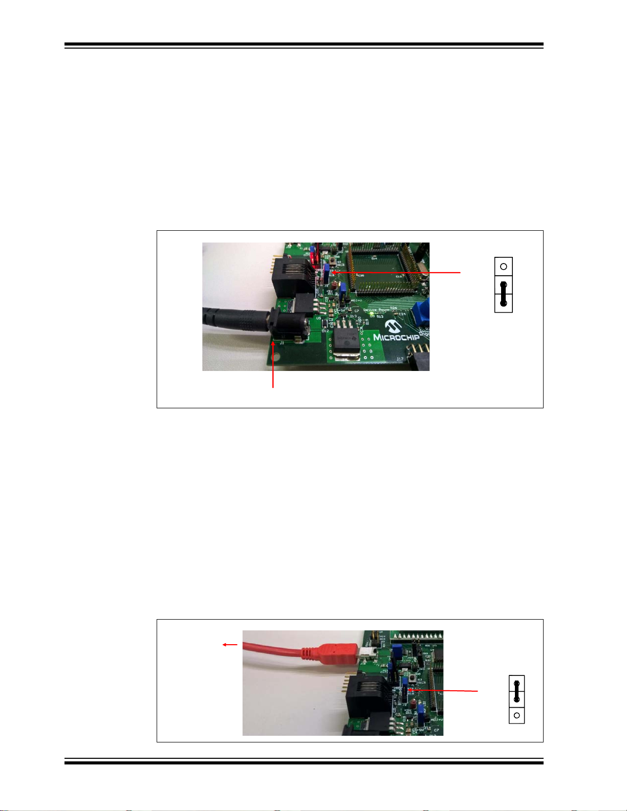
2.5 POWERING THE BOARD
The Explorer 8 Development Board can be powered-up in two ways: External 9V DC
supply and USB power.
2.5.1 External 9V Power Supply
To power-up the board using an external 9V power supply:
• Plug the 9V power supply to a wall outlet.
• Connect the 9V power supply to the board through the barrel connector placed on
the lower left corner of the board.
• Place J2 in the position shown in Figure 2-6.
FIGURE 2-6: USING THE 9V EXTERNAL SUPPLY
One of the on-board regulators will reduce this voltage to 5V which can be measured
through Test Points TP1 and TP7. For 3.3V, the 5V output will be further reduced
through a 3.3V regulator. Make sure to attach J24 before measuring the 3.3V output at
TP6. The board also supports other voltage values through an adjustable voltage
regulator. The variable voltage can be measured through TP5. For more details on
varying the voltage values, see Section
Section 2.6 “Selecting Vdd Values”.
2.5.2 USB Power
The Explorer 8 Development Board can also be powered through USB. The board will
draw +5V power from a host device such as a PC by connecting a USB cable between
the on-board micro USB socket and the PC’s USB port. The micro USB cable is
included in the Explorer 8 Development Kit.
Figure 2-7 shows how to connect the USB cable to the micro USB socket and J2 setting
for USB-powered configuration.
FIGURE 2-7: USB-POWERED BOARD CONFIGURATION
DS40001812A-page 26 2015 Microchip Technology Inc.
Page 27

2.6 SELECTING VDD VALUES
J14
J30
+5V
+3.3V
ADJ+V
J14
J30
+5V
+3.3V
ADJ+V
J14
J30
+5V
+3.3V
ADJ+V
V_VAR = 5V
(Fixed)
V_VAR = 3.3V
(Fixed)
V_VAR = ADJ + V
REF
(Variable)
V
OUT
V
REF
1
R2
R1
------ -+
I
ADJ
R2+=
V
OUT
1.25V 1
R2
R1
------ -+
=
Where:
R2 R20 R102
R20 R102
R20 R102+
----------------------------------==
R1 R19 R101
R19 R101
R19 R101+
----------------------------------==
The Explorer 8 Development Board is capable of supplying 5V, 3.3V and variable
supply voltages between 1.2 and 5V through dedicated on-board regulators. The
variable supply voltage, called V_VAR (also equal to V
and the on-board components.
2.6.1 Varying the Device Voltage
Figure 2-8 shows the jumper configuration for the three voltage settings.
FIGURE 2-8: JUMPER CONFIGURATION FOR DIFFERENT DEVICE
Getting Started
DD), is used to power the device
VOLTAGES
2.6.2 Calculating other VDD Values
For voltages other than 5V and 3.3V, jumpers J14 and J30 must be configured for
variable supply as shown in Figure 2-8. Other V
LM317 adjustable voltage regulator by populating the PIM board’s R101 and R102 with
different value resistors. This section discusses how to calculate alternate values for
these resistors. For detailed information, see the LM317 data sheet.
Note: R101 and R102 are named R1 and R2, respectively, in other PIM boards.
These must not be confused with the R1 and R2 values discussed in this
section.
EQUATION 2-1: LM317 REGULATOR VOLTAGE OUTPUT
IADJ is minimized by the LM317 and can be neglected or assumed to be zero. VREF is
the reference voltage developed by the LM317 between the output and adjustment
terminal, and is typically equal to 1.25V.
Therefore, the equation can be rewritten as shown in Equation 2-2.
EQUATION 2-2: CALCULATING THE LM317 OUTPUT VOLTAGE
DD values can be produced by the
2015 Microchip Technology Inc. DS40001812A-page 27
Page 28

Explorer 8 Development Board User’s Guide
The Explorer 8 Development Board’s R20 and R19 resistors have their default values
of 1 kΩ and 330Ω, respectively. Without R102 and R101 being inserted in parallel on
the PIM board, V
To calculate a desired V
1. Solve for R2, given R1 = R19 = 330Ω.
2. Now knowing R2 and R20, solve for R102.
3. Determine the nearest available resistor value for R102 and recalculate the
resulting V_VAR to make sure it does not exceed the maximum V
being used.
For devices that are not mounted on a PIM but need a supply voltage other than 5V or
3.3V, external resistors may be connected to the ADJ pin of J29. A resistor connected
between ADJ and ground is equivalent to R102 and a resistor connected between ADJ
and V_VAR is equivalent to R101. Calculate the resistor values using the equations
previously discussed in this section.
OUT = 1.25V(1 + 1 kΩ/330Ω) = 5.04V.
OUT:
DD for the part
DS40001812A-page 28 2015 Microchip Technology Inc.
Page 29

EXPLORER 8 DEVELOPMENT BOARD
Power Up
Microchip
Explorer 8 Demo
Voltmeter
S1=Now S2=Next
Volts = x.xxV
S1=Exit
Toggle LEDs
S1=Now S2=Next
LEDs Toggle
S1=Exit
LED Dimming
S1=Now S2=Next
Turn POT R25
S1=Exit
Chapter 3. Tutorial Program
The tutorial program is pre-programmed into the PIC16F1719 that comes with the
Explorer 8 demo board. This program, which can be downloaded from the Microchip
web site (www.microchip.com/explorer8), is built using the MPLAB X IDE and the
MPLAB
the MPLAB
generates seamless, easy to understand drivers and initializers that are inserted into
your project. For more information on MCC, visit www.microchip.com/mcc.
3.1 T UTORIAL PROGRAM OPERATION
The tutorial program consists of three components: Voltmeter, LED Toggle and LED
dimming. The flowchart in Figure 3-1 illustrates the button navigation through the entire
program.
The different components are displayed on the LCD and the LEDs. The data sent to the
LCD is simultaneously transmitted by the EUSART module of the device to the
USB-to-UART/I
through a serial terminal program (see
Communication”
8-bit Data, No Parity and 1 Stop Bit. For the board supply and jumper configurations,
see
XC8 Complier. It also utilizes the macros, drivers and initializers generated by
®
Code Configurator (MCC). MCC is a plug-in for MPLAB X IDE that
2
C converter and can, therefore, be viewed on the host PC monitor
). Make sure that the terminal program is configured to 9600 Baud,
Section 2.1 “Explorer 8 with Pre-Programmed Device”.
USER’S GUIDE
Section 2.4 “Connecting to Host PC for USB
FIGURE 3-1: TUTORIAL PROGRAM FLOWCHART
2015 Microchip Technology Inc. DS40001812A-page 29
Page 30

Explorer 8 Development Board User’s Guide
To select menu options, use the S1 and S2 buttons on the board (see Figure 3-2).
FIGURE 3-2: BUTTON SWITCHES FOR MENU SELECTION
When the board is powered up, a “Microchip Explorer 8 Demo” text is displayed on the
LCD and sent to the serial terminal as well. After a few seconds, the program proceeds
to the first component.
1. Voltmeter
This mode uses the Analog-to-Digital Converter (ADC) module to measure the voltage
across the R25 potentiometer and display a value between 0.00V and 5.00V on the
LCD. (In general, the displayed value is between 0.00V to V_VAR).
FIGURE 3-3: VOLTMETER DISPLAY AND COMPONENT
The voltage reading is updated continuously until the mode is exited by pressing S1.
FIGURE 3-4: VOLTAGE DISPLAY
2. LEDs Toggle
This mode toggles LEDs D1 and D2 alternately with D3 and D4 between fully On and
fully Off states every 100 milliseconds.
FIGURE 3-5: LED TOGGLE DISPLAY
DS40001812A-page 30 2015 Microchip Technology Inc.
Page 31

Tutorial Program
3. LED Dimming
Both the Complementary Output Generator (COG) and Analog-to-Digital Converter
(ADC) modules are implemented in this mode. The COG produces a pulse-width
modulated output whose duty cycle is determined by the measured ADC value across
the R25 potentiometer. The COG output controls the brightness of the D6, D7 and D8
LEDs.
FIGURE 3-6: LED DIMMING DISPLAY
Turning the potentiometer clockwise increases the brightness of the LEDs while
rotating it counterclockwise dims the LEDs.
FIGURE 3-7: LED DIMMING
Exiting this mode by pressing S1 brings the program back to Voltmeter.
3.2 SOURCE CODE AND DATA SHEETS
The tutorial program is available on the Microchip web site:
(www.microchip.com/explorer8)
The source codes and hex files are contained in the
project file.
For information on reprogramming the device with new or modified code, see
Section 2.3 “Programming the Microcontrollers”.
Explorer_8_Demo_MCC.X
2015 Microchip Technology Inc. DS40001812A-page 31
Page 32

Explorer 8 Development Board User’s Guide
NOTES:
DS40001812A-page 32 2015 Microchip Technology Inc.
Page 33

Appendix A. Hardware Details
A.1 HARDWARE ELEMENTS
A.1.1 Processor Sockets
The Explorer 8 Development Board contains four processor sockets:
• 20-pin Socket – for 8/14/20-pin DIP microcontrollers
• 28-pin Socket – for 28-pin DIP microcontrollers
• 40-pin Socket – for 40-pin DIP microcontrollers
• 84-pin PIM Socket – for 44/64/80-pin PIM-mounted microcontrollers
Only one device may be used at a time. Remove unnecessary devices before
demonstrating your program.
For a complete list of 8-bit PIC microcontrollers and available PIMs, go to the Microchip
web site at www.microchip.com.
A.1.2 Display
Eight blue LEDs (D8:D1) are connected to the <RB3:RB0> and <RD3:RD0> pins of
each processor type, respectively. These pins are set high to light the LEDs.
LEDs D8:D5 may be disconnected by removing jumper J21 while LEDs D4:D1 may be
disconnected by removing J7.
D5 lights up once J21 is attached because RB0 is also connected to switch SW1 and
this pin is always pulled up to V_VAR.
EXPLORER 8 DEVELOPMENT BOARD
USER’S GUIDE
A.1.3 Power Supply
The Explorer 8 Development Board does not come with a power supply but it comes
with a micro USB cable for powering the board via USB. Using USB power, however,
limits the supply to only 100 mA. Using the 9V external supply, both 3.3V and 5.0
supplies are capable of up to 1A. Microchip’s 9V, 1.3A power supply (Part Number
AC002014) can be used if external supply is needed. When using an external supply,
the board is limited to a maximum of 5A, imposed on the breadboard contacts.
The board is populated with two fixed (U5 and U1) and one variable (U2) voltage
regulators to provide 5.0V, 3.3V and any voltage between 1.2V and 5V.
Note: For power supply selection, see Section 2.5 “Powering the Board” and
Section 2.6 “Selecting Vdd Values”.
2015 Microchip Technology Inc. DS40001812A-page 33
Page 34

Explorer 8 Development Board User’s Guide
A.1.4 Micro USB Port
A micro USB port is provided not just for powering the board but also for
communications between the device and a host PC via USB. The micro USB cable
included in the Explorer 8 Development Board Kit can be used to connect the board’s
micro USB port to the host PC’s USB port.
The on-board MCP2221 is a USB-to-UART/I
connectivity for devices with UART or I
Note: For details on this connection, see Section 2.4 “Connecting to Host PC
for USB Communication”
A.1.5 Switches
Three switches are provided on the board:
• S1 – Active-low switch connected to RB0
• S2 – Active-low switch connected to RA5
• S3 – MCLR
When pressed, the switches are grounded. When idle, they are pulled high (V_VAR).
to hard reset the processor
A.1.6 Oscillator Options
2
C serial converter that enables USB
2
C interfaces.
.
An 8 MHz crystal (Y1) serves as the controller’s primary oscillator. It can also be used
as TMR0’s clock source for some devices depending upon the configured J36 and J37
settings.
A.1.7 Analog Input (Potentiometer)
A 10 kΩ potentiometer (R25) is connected through a series resistor to RA0/AN0.
The potentiometer can be adjusted from V_VAR to GND to provide an analog input to
one of the device ADC channels.
A.1.8 ICD Connector
The MPLAB® ICD 3 can be connected to the modular connector (J26) for programming
and in-circuit debugging. Jumpers J51 and J52 define the connection of the in-circuit
debugger to the device pins. The MPLAB REAL ICE can also be connected to this
interface.
Note: For details, see Section Section 2.3.3 “Programming the
Microcontroller”
.
A.1.9 PICkit™ Connector
A PICkit 3 In-Circuit Debugger/Programmer can be connected to the 6-pin interface
provided by J12. Jumpers J51 and J52 define the connection of the PICkit3 to the
microcontroller pins.
Note: For details, see Section 2.4 “Connecting to Host PC for USB
Communication”
.
DS40001812A-page 34 2015 Microchip Technology Inc.
Page 35

Hardware Details
A.1.10 PICtail™ and PICtail Plus Expansion Connectors
The PICtail interface enables the Explorer 8 Development Board to be connected
directly to available PICtail daughter board cards. The following female headers are
available to support different PIC microcontroller connections to PICtail daughter cards
and for user access to MCU pins:
• 2x14 Socket (J3) – to support 8/14/18/20/28-pin devices
• 2x6 Socket (J11) – to support up to 44-pin devices
• 2x10 Socket (J5) – to support up to 68-pin devices
• 2x8 Socket (J28) – to support up to 80-pin devices
The PICtail Plus connectors (J19) are the card-edge modular connector found on the
right part of the board. It is based on a 120-pin connection divided into three sections
of 30 pins, 30 pins and 56 pins. Each 30-pin section provides connections to all of the
serial communication peripherals, as well as many I/O ports, external interrupts and
ADC channels. This provides enough signals to develop many different expansion
interfaces for different PICtail daughter cards.
For available PICtail daughter cards, visit the Microchip web site at
www.microchip.com.
A.1.11 mikroBUS™ Connectors
Two MikroElektronika Click boards may be loaded into the sockets J32 or J35. Various
communication ports and interfaces are controlled by Jumpers J41 through J50. Power
and ground for the Click boards is supplied through the existing connections to the
sockets.
Note: Sample jumper configurations are provided in Ta b le 1 - 1.
A.1.12 Pmod™ Connectors
Two Digilent Pmod interfaces are available on the bottom middle of the Explorer 8
Development Board. Both sockets are the 12-pin version of the Digilent Pmod and
provide eight I/O signal pins, two power pins and two ground pins. The signals are
arranged so that they provide two of the 6-pin interfaces stacked.
Note: Sample jumper configurations are provided in Ta b le 1 - 1.
A.1.13 Configurable In-line Connector
A 20-pin single in-line socket (J33) is provided for connection with expansion boards.
The socket is connected in parallel to the first line of a 2x20 female header (J25)
making it a configurable in-line connector. The second line of J25 has each of its pin
socket connected to the 3.3V supply while another 2x20 female header (J39) makes
each of its pin socket available with 5V.
A.1.14 LCD
An LCD with two lines, 16 characters each, is connected to the SPI I/O expander,
MCP23S17. The two control lines and eight data lines are connected to the I/O
expander. The I/O expander has an SPI interface that connects it to the microcontroller.
The LCD is disabled or enabled through jumper J61.
2015 Microchip Technology Inc. DS40001812A-page 35
Page 36

Explorer 8 Development Board User’s Guide
A.1.15 Sample Devices
A sample part programmed with a simple program is included in the Explorer 8
Development Board Kit. The device’s I/O features and port connections are listed in
Table A-1.
TABLE A-1: SAMPLE DEVICE I/O FEATURES AND CONNECTIONS
Device LEDs USB S1 S2 S3 LCD
PIC16F1719 RB3:RB0
RD3:RD0
RC6 RB0 RA5 MCLR RC3
RC5
RA2
RB5
POT
R25
PICkit™
RA0 RB7
RB6
ICD/
Y1
RA7
RA6
DS40001812A-page 36 2015 Microchip Technology Inc.
Page 37

A.2 BOARD LAYOUT AND SCHEMATICS
FIGURE A-1: EXPLORER 8 DEVELOPMENT BOARD
Hardware Details
2015 Microchip Technology Inc. DS40001812A-page 37
Page 38

DS40001812A-page 38 2015 Microchip Technology Inc.
FIGURE A-2: EXPLORER 8 DEVELOPMENT SCHEMATIC - 1
Explorer 8 Development Board User’s Guide
Page 39

2015 Microchip Technology Inc. DS40001812A-page 39
FIGURE A-3: EXPLORER 8 DEVELOPMENT SCHEMATIC - 2
Hardware Details
Page 40

DS40001812A-page 40 2015 Microchip Technology Inc.
FIGURE A-4: EXPLORER 8 DEVELOPMENT SCHEMATIC - 3
Explorer 8 Development Board User’s Guide
Page 41

Worldwide Sales and Service
AMERICAS
Corporate Office
2355 West Chandler Blvd.
Chandler, AZ 85224-6199
Tel: 480-792-7200
Fax: 480-792-7277
Technical Support:
http://www.microchip.com/
support
Web Address:
www.microchip.com
Atlanta
Duluth, GA
Tel: 678-957-9614
Fax: 678-957-1455
Austin, TX
Tel: 512-257-3370
Boston
Westborough, MA
Tel: 774-760-0087
Fax: 774-760-0088
Chicago
Itasca, IL
Tel: 630-285-0071
Fax: 630-285-0075
Cleveland
Independence, OH
Tel: 216-447-0464
Fax: 216-447-0643
Dallas
Addison, TX
Tel: 972-818-7423
Fax: 972-818-2924
Detroit
Novi, MI
Tel: 248-848-4000
Houston, TX
Tel: 281-894-5983
Indianapolis
Noblesville, IN
Tel: 317-773-8323
Fax: 317-773-5453
Los Angeles
Mission Viejo, CA
Tel: 949-462-9523
Fax: 949-462-9608
New Yor k , NY
Tel: 631-435-6000
San Jose, CA
Tel: 408-735-9110
Canada - Toronto
Tel: 905-673-0699
Fax: 905-673-6509
ASIA/PACIFIC
Asia Pacific Office
Suites 3707-14, 37th Floor
Tower 6, The Gateway
Harbour City, Kowloon
Hong Kong
Tel: 852-2943-5100
Fax: 852-2401-3431
Australia - Sydney
Tel: 61-2-9868-6733
Fax: 61-2-9868-6755
China - Beijing
Tel: 86-10-8569-7000
Fax: 86-10-8528-2104
China - Chengdu
Tel: 86-28-8665-5511
Fax: 86-28-8665-7889
China - Chongqing
Tel: 86-23-8980-9588
Fax: 86-23-8980-9500
China - Dongguan
Tel: 86-769-8702-9880
China - Hangzhou
Tel: 86-571-8792-8115
Fax: 86-571-8792-8116
China - Hong Kong SAR
Tel: 852-2943-5100
Fax: 852-2401-3431
China - Nanjing
Tel: 86-25-8473-2460
Fax: 86-25-8473-2470
China - Qingdao
Tel: 86-532-8502-7355
Fax: 86-532-8502-7205
China - Shanghai
Tel: 86-21-5407-5533
Fax: 86-21-5407-5066
China - Shenyang
Tel: 86-24-2334-2829
Fax: 86-24-2334-2393
China - Shenzhen
Tel: 86-755-8864-2200
Fax: 86-755-8203-1760
China - Wuhan
Tel: 86-27-5980-5300
Fax: 86-27-5980-5118
China - Xian
Tel: 86-29-8833-7252
Fax: 86-29-8833-7256
ASIA/PACIFIC
China - Xiamen
Tel: 86-592-2388138
Fax: 86-592-2388130
China - Zhuhai
Tel: 86-756-3210040
Fax: 86-756-3210049
India - Bangalore
Tel: 91-80-3090-4444
Fax: 91-80-3090-4123
India - New Delhi
Tel: 91-11-4160-8631
Fax: 91-11-4160-8632
India - Pune
Tel: 91-20-3019-1500
Japan - Osaka
Tel: 81-6-6152-7160
Fax: 81-6-6152-9310
Japan - Tokyo
Tel: 81-3-6880- 3770
Fax: 81-3-6880-3771
Korea - Daegu
Tel: 82-53-744-4301
Fax: 82-53-744-4302
Korea - Seoul
Tel: 82-2-554-7200
Fax: 82-2-558-5932 or
82-2-558-5934
Malaysia - Kuala Lumpur
Tel: 60-3-6201-9857
Fax: 60-3-6201-9859
Malaysia - Penang
Tel: 60-4-227-8870
Fax: 60-4-227-4068
Philippines - Manila
Tel: 63-2-634-9065
Fax: 63-2-634-9069
Singapore
Tel: 65-6334-8870
Fax: 65-6334-8850
Tai wan - Hsin Chu
Tel: 886-3-5778-366
Fax: 886-3-5770-955
Taiwan - Kaohsiung
Tel: 886-7-213-7828
Taiwan - Taipei
Tel: 886-2-2508-8600
Fax: 886-2-2508-0102
Thailand - Bangkok
Tel: 66-2-694-1351
Fax: 66-2-694-1350
EUROPE
Austria - Wels
Tel: 43-7242-2244-39
Fax: 43-7242-2244-393
Denmark - Copenhagen
Tel: 45-4450-2828
Fax: 45-4485-2829
France - Paris
Tel: 33-1-69-53-63-20
Fax: 33-1-69-30-90-79
Germany - Dusseldorf
Tel: 49-2129-3766400
Germany - Karlsruhe
Tel: 49-721-625370
Germany - Munich
Tel: 49-89-627-144-0
Fax: 49-89-627-144-44
Italy - Milan
Tel: 39-0331-742611
Fax: 39-0331-466781
Italy - Venice
Tel: 39-049-7625286
Netherlands - Drunen
Tel: 31-416-690399
Fax: 31-416-690340
Poland - Wars a w
Tel: 48-22-3325737
Spain - Madrid
Tel: 34-91-708-08-90
Fax: 34-91-708-08-91
Sweden - Stockholm
Tel: 46-8-5090-4654
UK - Wokingham
Tel: 44-118-921-5800
Fax: 44-118-921-5820
07/14/15
2015 Microchip Technology Inc. DS40001812A-page 41
 Loading...