

Page 1

ExpLoRer Starter Kit User Guide
Page 2

2
Introducing: ExpLoRer
Page 3

3
Why Arduino??
Open Source
Industry standard
Easily accessible
Free IDEs
No flashing tools needed – only a USB cable
Simple structure (setup & loop) with examples
Excellent HAL
Re-use projects across AVR, PIC, Cortex
cores
Hugely popular!
Page 4

5
ExpLoRer - Arduino
Micro USB:
Arduino IDE
& charging
LiR2450
rechargeable
battery
120mAh, 3.6V
Atmel SAM-D21
Cortex®-M0+ based
microcontroller
Standard headers
for feature expansion
(sensors, GPS, solar)
Page 5
6
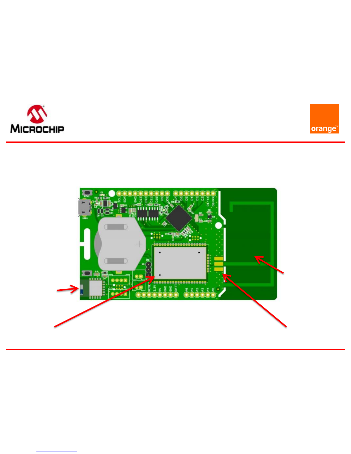
ExpLoRer - Wireless
RN4871
BT-Smart
RN2483a
LoRaWAN
Low-cost
(removable)
PCB IFA
antenna
Footprint for
optional SMA
Page 6

7
ExpLoRer
RGB LED for status
Indication
Standard headers
for feature expansion
(sensors, GPS, solar)
MCP9700AT
Temperature
Sensor
Blue
LED
Page 7

8
ExpLoRer - Security
ECC508A
Crypto Device
Page 8

9
ExpLoRer
Micro USB:
Arduino IDE
& charging
LiR2450
rechargeable
battery
120mAh, 3.6V
RGB LED for status
Indication
RN4871
BT-Smart
Atmel SAM-D21
Cortex®-M0+ based
microcontroller
RN2xx3
LoRaWAN
Low-cost
(removable)
PCB IFA
antenna
Footprint for
optional SMA
Standard headers
for feature expansion
(sensors, GPS, solar)
ECC508A
Crypto Device
MCP9700AT
Temperature
Sensor
Blue
LED
Page 9

13
Specifications
Microcontroller
Microchip ATSAMD21J18
32
-Bit ARM Cortex M0+
Compatibility
Arduino M0 Compatible
Size
94
x 53 mm
Operating Voltage
3.3V
I/O Pins
20
Analog Output Pin
12
-bit ADC
External Interrupts
Available on all pins
DC Current per I/O pin
7 mA
Flash Memory
256
KB (internal)
and
4MB (external SST25PF040C flash)
SRAM
32KB
EEPROM
Up to 16KB by emulation
Page 10

14
Specifications
Clock Speed
48 MHz
Power
5V USB power and/or 3.7
Lithium battery
Charging
Solar charge controller, up to 500mA
charge current
LED
RGB LED, Blue LED
LoRa
Microchip
RN2483a Module
Bluetooth
Microchip
RN4871 Module
CryptoAuthentication
Microchip ATECC508A
Temperature sensor
Microchip MCP9700AT
USB
Micro USB
Port
Page 11

15
Pinout
USB
Page 12

16
Pins Definition
Definition
Pin index
Blue LED
LED_BUILTIN
13
RGB
Red LED
LED_RED
16
RGB Green LED
LED_GREEN
17
RGB Blue LED
LED_BLUE
18
Bluetooth Wake
BLUETOOTH_WAKE
19
LoRa
Reset
LORA_RESET
45
Bluetooth Reset
BT_RESET
46
Programmable
Button
BUTTON
47
Temperature
Sensor
TEMP_SENSOR
A6
Grove Header
-
14-15
Grove Header I2C
PIN_WIRE_SDA, PIN_WIRE_SCL
33-34
Page 13

17
Grove connector
The Seeedstudio Grove system is a seamless set of
open-source plug-and-play components. It simplifies
the study and electronic prototypes by proposing a
wide selection of sensors and actuators
You can find two types of grove connectors on the
board:
I2C
Analogic
Page 14
18
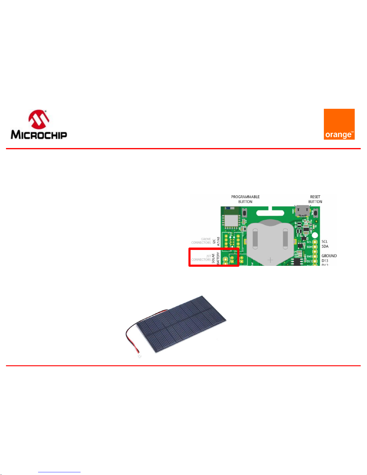
Solar power
You can plug on the board a solar panel
This input has some limitations
Maximum voltage : 5.5V
Maximum current : 500mA
Maximum power : 2.5W
You can use a 1.5W Solar Panel for example
Page 15

ARDUINO IDE
Setup
Page 16

20
Arduino IDE Setup
Download and install the latest Arduino IDE:
https://www.arduino.cc/en/Main/Software
Page 17

21
Board Setup
In order to install the board you will need to add the SODAQ
board manager URL:
http://downloads.sodaq.net/package_sodaq_samd_index.json
to File -> Preferences -> Additional Board Manager URLs:
Page 18

22
Board Setup
Then, the SODAQ SAMD Boards package will appear in the
Tools -> Board -> Board Manager
Install the latest SODAQ SAMD Boards package
Select the SODAQ ExpLoRer board from Tools -> Board
Page 19

24
Library Setup
Import the libraries provided by using:
Sketch -> Include Library -> Add .ZIP Library
Then you search for the file named ‘OrangeRn2483.zip’ that you
have previously downloaded on
https://partner.orange.com/wp-content/uploads/2017/07/OrangeRn2483.zip
Page 20

25
Arduino IDE Basis
Open a sketch example file (.ino)
From menu : File -> Examples -> OrangeRn2483
(1) Compile and check if the code has no error
Press the reset button twice within a second
to place the board into bootloader mode and
is expecting a new sketch
Select the ExpLoRer COM port assigned
(2) Upload the sketch to the board
(3) Open the Serial monitor for debugging
(1) (2) (3)
Page 21

26
Arduino IDE and
Sketch
setup()
Loop that runs only
once
loop()
Loop that runs
continuously
Page 22

27
Hardware Serials
The ExpLoRer has 4 hardware serials:
SerialUSB this is for debugging over the USB cable
Serial Serial is attached to pin D1/TX and D0/RX
Serial1 is connected to the RN4871 Bluetooth module
Serial2 is connected to the RN2483 LoRaWAN module
Software Serial refer to https://www.arduino.cc/en/Reference/SoftwareSerial
The sketch starts direct after uploading new code or when
connected to a power source. After opening a Serial Monitor the
code will not reset, add the following code to your sketch if you
want your sketch to wait for a Serial Monitor
void setup()
{
// put your setup code here, to run once:
// wait for SerialUSB or start after 10 seconds
while ((!SerialUSB) && (millis() < 10000)) ;
SerialUSB.begin(57600) ;
Serial.begin(57600) ;
Serial1.begin(115200) ;
Serial2.begin(57600) ;
}
void loop()
{
// put your main code here, to run repeatedly:
}
Page 23

28
Basics sketches
The Arduino IDE has some examples built in
Open the ExtractHardwareDevEUI sketch
File -> Examples -> OrangeRn2483
-> ExtractHardwareDevEUI
Page 24

MAIN FEATURES OF THE KIT
Getting Started
Page 25

30
Reset Button
On legacy Arduino board the reset button restarts
your program from the beginning
On the ExpLoRer board the reset button has two
modes:
Mode 1: simple click that acts as legacy Arduino reset
Mode 2: double click that starts the board in a bootloader mode.
In this mode, Arduino sketch is put on hold and the board awaits
the upload of a new sketch.
Warning:
When switching between mode 1 and 2 the COM port that you
see in Arduino IDE will change (but remains the same for a given
mode)
Page 26

31
Push Button
The ExpLoRer Starterkit has a programmable button
This example will light the built-in Blue LED when the button is
pushed
void setup()
{
// Configure the button as an input
// and enable the internal pull-up resistor
pinMode(BUTTON, INPUT_PULLUP) ;
pinMode(LED_BUILTIN, OUTPUT) ;
}
void loop()
{
// Read the button value into a variable
int sensorVal = digitalRead(BUTTON) ;
// Turn on the LED when the Button is pushed
if (sensorVal == HIGH)
{
digitalWrite(LED_BUILTIN, LOW) ;
}
else
{
digitalWrite(LED_BUILTIN, HIGH) ;
}
}
Page 27

32
RGB LED
int led = LED_RED; // the PWM pin the LED is attached to
int brightness = 0; // how bright the LED is
int fadeAmount = 5; // how many points to fade the LED by
// the setup routine runs once when you press reset:
void setup()
{
pinMode(led, OUTPUT) ;
}
// the loop routine runs over and over again forever:
void loop()
{
// set the brightness
analogWrite(led, brightness) ;
// change the brightness for next time through the loop:
brightness = brightness + fadeAmount ;
// reverse the direction of the fading at the ends of the
fade:
if (brightness == 0 || brightness == 255)
{
fadeAmount = -fadeAmount ;
}
// wait for 30 milliseconds to see the dimming effect
delay(30);
}
Page 28

33
Temperature Sensor
#define debugSerial SerialUSB
void setup()
{
pinMode(TEMP_SENSOR, INPUT) ;
// Set ADC resolution to 12 bits
analogReadResolution(12) ;
}
void loop()
{
// 10mV per C, 0C is 500mV
float mVolts = (float)analogRead(TEMP_SENSOR) * 3300.0 / 4096.0 ;
float temp = (mVolts - 500.0) / 10.0 ;
debugSerial.print(temp) ;
debugSerial.println(" C") ;
delay(1000) ;
}
Page 29

34
Battery Charging
USB power and Solar panel sources can be used for charging
Jumpers JP1 determines which battery is used/charged
(1) External battery
(2) Internal battery
(1) {
(2) {
Solar
Batt
Page 30

37
BLE Module
Arduino library for using the Microchip RN487x BLE module
#include "RN487x_BLE.h"
#define bleSerial Serial1
void setup()
{
rn487xBle.hwInit() ;
bleSerial.begin(rn487xBle.getDefaultBaudRate()) ;
rn487xBle.initBleStream(&bleSerial) ;
if (rn487xBle.swInit())
{
rn487xBle.enterCommandMode() ;
rn487xBle.stopAdvertising() ;
rn487xBle.setAdvPower(3) ;
rn487xBle.setSerializedName("Microchip") ;
rn487xBle.clearAllServices() ;
rn487xBle.reboot() ;
}
}
void loop()
{
}
Page 31

39
LoRa® Communication
Arduino library for using the Microchip RN2483 LoRaWAN
module: OrangeRn2483
You can find a complete document on this library and its
functions in the library’s file
#include <OrangeRn2483.h>
// The following keys are for structure purpose only. You must define YOUR OWN.
const int8_t appEUI[8] = { 0x00, 0x00, 0x00, 0x00, 0x00, 0x00, 0x00, 0x00 };
const int8_t appKey[16] = { 0x00, 0x00, 0x00, 0x00, 0x00, 0x00, 0x00, 0x00, 0x00,
0x00, 0x00, 0x00, 0x00, 0x00, 0x00, 0x00 };
bool joinNetwork()
{
OrangeRN2483.setDataRate(DATA_RATE_1); // Set DataRate to SF11/125Khz
return OrangeRN2483.joinNetwork(appEUI, appKey);
}
bool SendLoRaMessage()
{
const uint8_t size = 5;
int8_t port = 5;
int8_t data[size] = { 0x48, 0x65, 0x6C, 0x6C, 0x6F }; // Hello
return OrangeRN2483.sendMessage(data, size, port); // send unconfirmed message
}
Page 32

Orange Live Objects
Getting Started
Page 33

41
Let’s get started
Provision your LoRa end device to join the network
The devEUI is provided by the ExpLoRer board
Get and note the hardware devEUI of the board by using the
ExtractHardwareDevEUI sketch
The application identifier (appEUI) is 8 bytes long (16 hexadecimal characters).
You can use this one 4578704C6F526572
Or create your own
The application session key (appKey) is specific for the end-device. It is 16 bytes
long (32 hexadecimal characters).
It is safer to create your own appKey
Or you can create one using {FFEEDDCCBBAA9988} as the 8 first bytes and the device’s devEUI for
the 8 last bytes. This option presents a security risk.
Write down your keys here for safe keeping :
devEUI =
appEUI =
appKEY =
Page 34

42
Orange Live Objects
Go to the following URL to access Live Objects :
https://lpwa.liveobjects.orange-business.com/#/login
You can find some useful videos about Live Objects
on this website :
https://www.youtube.com/channel/UCqiOhIRIpjRvR3Bw0hMLciw
Page 35

43
Provisioning a device
Create your device within Orange Live Objects by adding the
activation keys and the right profile
AppKey
DevEui
AppEui
Choose the profile
Michrochip RN2483
Page 36

44
Provisioning a device
In addition to the activation keys you have to
choose the profil Microchip RN2483
Page 37

45
Provisioning a device
You device is now registered
Page 38

46
Testing the network
Open the SendPayload sketch to test your device
File -> Examples -> OrangeRn2483 -> SendPayload
This sketch will send 3 payloads
Modify the file with your own keys in HEX format (0x)
Here is what your code should look like :
// The following keys are for structure purpose only. You must define YOUR OWN.
const int8_t appEUI[8] = { 0x00, 0x00, 0x00, 0x00, 0x00, 0x00, 0x00, 0x00 };
const int8_t appKey[16] = { 0x00, 0x00, 0x00, 0x00, 0x00, 0x00, 0x00, 0x00,
0x00, 0x00, 0x00, 0x00, 0x00, 0x00, 0x00, 0x00 };
Page 39

47
Testing the network
(1) Upload the sketch to the board
(2) Open the Serial monitor for debugging
You should see the following monitor :
(2)
(1)
Page 40

48
Visualizing Lora Messages
To see the 3 payloads that have been sent :
On Live Object select your device
You are redirected to this page :
Page 41

49
Visualizing uplinks
Click on the uplink tab
You can now see the 3 payloads you just sent
Page 42

50
Downlinks
Downlink is about sending payloads from Live
Object to the device
Click on the downlink tab after selecting your device
Then you select the send button
Then you fill in the port number and the data to send in
hexadecimal form and click on send
Page 43

51
Receiving downlinks
To visualize your downlink use the GetReceivedData
sketch
File -> Examples -> OrangeRn2483 -> GetReceivedData
Then send the payload from Live Object
Finally open the Serial Monitor
You should see the data you sent
Page 44

Thank You
Note: The Microchip name and logo, dsPIC, MPLAB and PIC are registered trademarks of Microchip Technology Inc. in the
U.S.A. and other countries.
MiWi, PICDEM and PICtail are trademarks of Microchip Technology Inc. in the U.S.A. and other countries.
All other trademarks mentioned herein are property of their respective companies.
 Loading...