

Page 1

EVB-USB4x12
Evaluation Board
User’s Guide
2019 Microchip Technology Inc. DS50002889A
Page 2

Note the following details of the code protection feature on Microchip devices:
QUALITYMANAGEMENTSYSTEM
CERTIFIEDBYDNV
== ISO/TS16949==
• Microchip products meet the specification contained in their particular Microchip Data Sheet.
• Microchip believes that its family of products is one of the most secure families of its kind on the market today, when used in the
intended manner and under normal conditions.
• There are dishonest and possibly illegal methods used to breach the code protection feature. All of these methods, to our
knowledge, require using the Microchip products in a manner outside the operating specifications contained in Microchip’s Data
Sheets. Most likely, the person doing so is engaged in theft of intellectual property.
• Microchip is willing to work with the customer who is concerned about the integrity of their code.
• Neither Microchip nor any other semiconductor manufacturer can guarantee the security of their code. Code protection does not
mean that we are guaranteeing the product as “unbreakable.”
Code protection is constantly evolving. We at Microchip are committed to continuously improving the code protection features of our
products. Attempts to break Microchip’s code protection feature may be a violation of the Digital Millennium Copyright Act. If such acts
allow unauthorized access to your software or other copyrighted work, you may have a right to sue for relief under that Act.
Information contained in this publication regarding device applications and the like is provided only for your convenience and may be
superseded by updates. It is your responsibility to ensure that your application meets with your specifications. MICROCHIP MAKES NO
REPRESENTATIONS OR WARRANTIES OF ANY KIND WHETHER EXPRESS OR IMPLIED, WRITTEN OR ORAL, STATUTORY OR
OTHERWISE, RELATED TO THE INFORMATION, INCLUDING BUT NOT LIMITED TO ITS CONDITION, QUALITY, PERFORMANCE,
MERCHANTABILITY OR FITNESS FOR PURPOSE. Microchip disclaims all liability arising from this information and its use. Use of Micro-
chip devices in life support and/or safety applications is entirely at the buyer’s risk, and the buyer agrees to defend, indemnify and hold
harmless Microchip from any and all damages, claims, suits, or expenses resulting from such use. No licenses are conveyed, implicitly or
otherwise, under any Microchip intellectual property rights unless otherwise stated.
Trademarks
The Microchip name and logo, the Microchip logo, AnyRate, AVR, AVR logo, AVR Freaks, BitCloud, chipKIT, chipKIT logo, CryptoMemory,
CryptoRF, dsPIC, FlashFlex, flexPWR, Heldo, JukeBlox, KeeLoq, Kleer, LANCheck, LINK MD, maXStylus, maXTouch, MediaLB, megaAVR,
MOST, MOST logo, MPLAB, OptoLyzer, PIC, picoPower, PICSTART, PIC32 logo, Prochip Designer, QTouch, SAM-BA, SpyNIC, SST, SST
Logo, SuperFlash, tinyAVR, UNI/O, and XMEGA are registered trademarks of Microchip Technology Incorporated in the U.S.A. and other
countries.
ClockWorks, The Embedded Control Solutions Company, EtherSynch, Hyper Speed Control, HyperLight Load, IntelliMOS, mTouch, Precision
Edge, and Quiet-Wire are registered trademarks of Microchip Technology Incorporated in the U.S.A.
Adjacent Key Suppression, AKS, Analog-for-the-Digital Age, Any Capacitor, AnyIn, AnyOut, BodyCom, CodeGuard, CryptoAuthentication,
CryptoAutomotive, CryptoCompanion, CryptoController, dsPICDEM, dsPICDEM.net, Dynamic Average Matching, DAM, ECAN, EtherGREEN,
In-Circuit Serial Programming, ICSP, INICnet, Inter-Chip Connectivity, JitterBlocker, KleerNet, KleerNet logo, memBrain, Mindi, MiWi,
motorBench, MPASM, MPF, MPLAB Certified logo, MPLIB, MPLINK, MultiTRAK, NetDetach, Omniscient Code Generation, PICDEM,
PICDEM.net, PICkit, PICtail, PowerSmart, PureSilicon, QMatrix, REAL ICE, Ripple Blocker, SAM-ICE, Serial Quad I/O, SMART-I.S., SQI,
SuperSwitcher, SuperSwitcher II, Total Endurance, TSHARC, USBCheck, VariSense, ViewSpan, WiperLock, Wireless DNA, and ZENA are
trademarks of Microchip Technology Incorporated in the U.S.A. and other countries.
SQTP is a service mark of Microchip Technology Incorporated in the U.S.A.
Silicon Storage Technology is a registered trademark of Microchip Technology Inc. in other countries.
GestIC is a registered trademark of Microchip Technology Germany II GmbH & Co. KG, a subsidiary of Microchip Technology Inc., in other
countries.
All other trademarks mentioned herein are property of their respective companies.
© 2019, Microchip Technology Incorporated, All Rights Reserved.
ISBN: 978-1-5224-4560-9
Microchip received ISO/TS-16949:2009 certification for its worldwide
headquarters, design and wafer fabrication facilities in Chandler and
Tempe, Arizona; Gresham, Oregon and design centers in California
and India. The Company’s quality system processes and procedures
are for its PIC
devices, Serial EEPROMs, microperipherals, nonvolatile memory and
analog products. In addition, Microchip’s quality system for the design
and manufacture of development systems is ISO 9001:2000 certified.
®
MCUs and dsPIC® DSCs, KEELOQ
®
code hopping
DS50002889A-page 2 2019 Microchip Technology Inc.
Page 3

EVB-USB4X12
EVALUATION BOARD
USER’S GUIDE
Table of Contents
Preface ........................................................................................................................... 5
Introduction............................................................................................................ 5
Document Layout .................................................................................................. 5
Conventions Used in this Guide ............................................................................ 6
The Microchip Web Site ........................................................................................ 7
Development Systems Customer Change Notification Service ............................ 7
Customer Support ................................................................................................. 7
Document Revision History ................................................................................... 8
Chapter 1. Overview
1.1 USB4712/USB4912 General Introduction ...................................................... 9
1.2 About EVB-USB4x12 ..................................................................................... 9
1.3 References ................................................................................................... 12
1.4 Acronyms and Definitions ............................................................................. 12
Chapter 2. Getting Started
2.1 Introduction ................................................................................................... 15
2.2 Kit Contents .................................................................................................. 15
2.3 Quick Start .................................................................................................... 15
2.3.1 Power Source ............................................................................................ 15
2.3.2 Default Firmware ....................................................................................... 15
2.3.3 Host Connection ........................................................................................ 16
2.3.4 Downstream Port Connections .................................................................. 16
Chapter 3. Hardware Configuration Options
3.1 Hardware Configuration Options .................................................................. 17
3.1.1 Configuration ............................................................................................. 17
3.1.2 Power Source ............................................................................................ 18
3.1.3 Board Power .............................................................................................. 18
3.1.4 Reset ......................................................................................................... 18
3.1.5 USB Ports .................................................................................................. 19
3.1.6 Spare GPIOs ............................................................................................. 19
3.1.7 SMBus/I2C Slave ...................................................................................... 20
3.1.8 USB to SMBus/I2C Master ........................................................................ 20
3.1.9 LED Indicators ........................................................................................... 21
3.1.10 Switches .................................................................................................. 21
3.1.11 Connector Descriptions ........................................................................... 22
3.1.12 Test Points .............................................................................................. 22
Appendix A. PCB Layers
A.1 Introduction .................................................................................................. 23
Appendix B. Schematics
2019 Microchip Technology Inc. DS50002889A-page 3
Page 4

EVB-USB4x12 Evaluation Board User’s Guide
B.1 Introduction .................................................................................................. 27
Appendix C. Bill of Materials
C.1 Introduction .................................................................................................. 33
Worldwide Sales and Service .....................................................................................38
DS50002889A-page 4 2019 Microchip Technology Inc.
Page 5

EVB-USB4X12
EVALUATION BOARD
USER’S GUIDE
Preface
NOTICE TO CUSTOMERS
All documentation becomes dated, and this manual is no exception. Microchip tools and
documentation are constantly evolving to meet customer needs, so some actual dialogs
and/or tool descriptions may differ from those in this document. Please refer to our web site
(www.microchip.com) to obtain the latest documentation available.
Documents are identified with a “DS” number. This number is located on the bottom of each
page, in front of the page number. The numbering convention for the DS number is
“DSXXXXXA”, where “XXXXX” is the document number and “A” is the revision level of the
document.
®
For the most up-to-date information on development tools, see the MPLAB
Select the Help menu, and then Topics to open a list of available online help files.
IDE online help.
INTRODUCTION
This chapter contains general information that will be useful to know before using the
USB4712/USB4912. Items discussed in this chapter include:
• Document Layout
• Conventions Used in this Guide
• The Microchip Web SiteThe Microchip Web Site
• Development Systems Customer Change Notification Service
• Customer Support
• Document Revision History
DOCUMENT LAYOUT
This document describes how to use the EVB-USB4x12 Evaluation Board as a
development tool for the USB4712/USB4912 1-Port USB 2.0 automotive hubs. The
manual layout is as follows:
• Chapter 1. “Overview” – This shows a brief description of the EVB-USB4x12
Evaluation Board.
• Chapter 2. “Getting Started” – This includes instructions on how to get started
with the EVB-USB4x12 Evaluation Board.
• Chapter 3. “Hardware Configuration Options” – This provides information
about the EVB-USB4x12 Evaluation Board battery charging features.
• Appendix A. “PCB Layers” – This appendix shows the EVB-USB4x12 Evalua-
tion Board PCB layers.
• Appendix B. “Schematics” – This appendix shows the EVB-USB4x12 Evalua-
tion Board schematics.
• Appendix C. “Bill of Materials” – This appendix includes the EVB-USB4x12
Evaluation Board Bill of Materials (BOM).
2019 Microchip Technology Inc. DS50002889A-page 5
Page 6

EVB-USB4x12 Evaluation Board User’s Guide
CONVENTIONS USED IN THIS GUIDE
This manual uses the following documentation conventions:
DOCUMENTATION CONVENTIONS
Description Represents Examples
Arial font:
Italic characters Referenced books MPLAB
Emphasized text ...is the only compiler...
Initial caps A window the Output window
A dialog the Settings dialog
A menu selection select Enable Programmer
Quotes A field name in a window or
dialog
Underlined, italic text with
right angle bracket
Bold characters A dialog button Click OK
N‘Rnnnn A number in verilog format,
Text in angle brackets < > A key on the keyboard Press <Enter>, <F1>
Courier New font:
Plain Courier New Sample source code #define START
Italic Courier New A variable argument file.o, where file can be
Square brackets [ ] Optional arguments mcc18 [options] file
Curly brackets and pipe
character: { | }
Ellipses... Replaces repeated text var_name [,
A menu path File>Save
A tab Click the Power tab
where N is the total number of
digits, R is the radix and n is a
digit.
Filenames autoexec.bat
File paths c:\mcc18\h
Keywords _asm, _endasm, static
Command-line options -Opa+, -Opa-
Bit values 0, 1
Constants 0xFF, ‘A’
Choice of mutually exclusive
arguments; an OR selection
Represents code supplied by
user
“Save project before build”
4‘b0010, 2‘hF1
any valid filename
[options]
errorlevel {0|1}
var_name...]
void main (void)
{ ...
}
®
IDE User’s Guide
DS50002889A-page 6 2019 Microchip Technology Inc.
Page 7

Preface
THE MICROCHIP WEB SITE
Microchip provides online support via our web site at www.microchip.com. This web
site is used as a means to make files and information easily available to customers.
Accessible by using your favorite Internet browser, the web site contains the following
information:
• Product Support – Data sheets and errata, application notes and sample
programs, design resources, user’s guides and hardware support documents,
latest software releases and archived software
• General Technical Support – Frequently Asked Questions (FAQs), technical
support requests, online discussion groups, Microchip consultant program
member listing
• Business of Microchip – Product selector and ordering guides, latest Microchip
press releases, listing of seminars and events, listings of Microchip sales offices,
distributors and factory representatives
DEVELOPMENT SYSTEMS CUSTOMER CHANGE NOTIFICATION SERVICE
Microchip’s customer notification service helps keep customers current on Microchip
products. Subscribers will receive e-mail notification whenever there are changes,
updates, revisions or errata related to a specified product family or development tool of
interest.
To register, access the Microchip web site at www.microchip.com, click on Customer
Change Notification and follow the registration instructions.
The Development Systems product group categories are:
• Compilers – The latest information on Microchip C compilers, assemblers, linkers
and other language tools. These include all MPLAB C compilers; all MPLAB
assemblers (including MPASM assembler); all MPLAB linkers (including MPLINK
object linker); and all MPLAB librarians (including MPLIB object librarian).
• Emulators – The latest information on Microchip in-circuit emulators. This
includes the MPLAB REAL ICE and MPLAB ICE 2000 in-circuit emulators.
• In-Circuit Debuggers – The latest information on the Microchip in-circuit
debuggers. This includes MPLAB ICD 3 in-circuit debuggers and PICkit 3 debug
express.
• MPLAB IDE – The latest information on Microchip MPLAB IDE, the Windows
Integrated Development Environment for development systems tools. This list is
focused on the MPLAB IDE, MPLAB IDE Project Manager, MPLAB Editor and
MPLAB SIM simulator, as well as general editing and debugging features.
• Programmers – The latest information on Microchip programmers. These include
production programmers such as MPLAB REAL ICE in-circuit emulator, MPLAB
ICD 3 in-circuit debugger and MPLAB PM3 device programmers. Also included
are non-production development programmers such as PICSTART Plus and
PIC-kit 2 and 3.
CUSTOMER SUPPORT
Users of Microchip products can receive assistance through several channels:
• Distributor or Representative
• Local Sales Office
• Field Application Engineer (FAE)
• Technical Support
2019 Microchip Technology Inc. DS50002889A-page 7
Page 8

EVB-USB4x12 Evaluation Board User’s Guide
Customers should contact their distributor, representative or field application engineer
(FAE) for support. Local sales offices are also available to help customers. A listing of
sales offices and locations is included in the back of this document.
Technical support is available through the web site at:
http://www.microchip.com/support
DOCUMENT REVISION HISTORY
Revisions Section/Figure/Entry Correction
DS50002889A
(05-29-19)
Initial release
DS50002889A-page 8 2019 Microchip Technology Inc.
Page 9

Chapter 1. Overview
1.1 USB4712/USB4912 GENERAL INTRODUCTION
The USB4712/USB4912 hub controller is a 1-port USB2.0 smart hub controller, which
is fully compliant with the USB2.0 Specification. The 1-port hub supports 480 Mbps
High-Speed (HS), 12 Mbps Full-Speed (FS) and 1.5 Mbps Low-Speed (LS) USB
signaling.
USB4712: The USB4712 is a 1-port retimer hub with AutoFlexConnect technology.
This hub is design for use within automotive systems which require an attached smart
phone to assume the host role when docked to the automotive head unit system.
AutoFlexConnect technology allows this hub to actively seek for a host connection on
both the default upstream or default downstream port. If a host is detected on the
default downstream port, but no host is detected on the default upstream port, then the
hub will automatically reconfigure itself and initiate FlexConnect to allow the host
detected on the default downstream port to enumerate the hub and any devices
attached to the USB4712 default upstream port. This allows a functional role swap
between the head unit and the smart phone to occur with no direct role swap commands issued to the USB4712. This hub also supports BC1.2 battery charging on the
default downstream port.
USB4912: The USB4912 is a 1-port hub with Multi-Host Endpoint Reflector technology.
This hub is designed for use within automotive systems which require an attached
smartphone to assume the host role when docked to the automotive head unit system.
With Multi-Host Endpoint Reflector technology, both the automotive head unit and the
smartphone may operate as USB hosts at the same time while exchanging data. A
command issued from the automotive head unit directed to the USB4912’s internal Hub
Feature Controller device is all that is needed to initiate a Multi-Host Endpoint Reflector
session. This hub also supports BC1.2 battery charging on the downstream port. The
USB4912 also has a secondary ‘remote port’ which can be used to daisy chain additional USB4912 hubs.
The USB4712/USB4912 smart hubs both have an embedded MCU for enabling
advanced features. These features include, hub configuration through upstream USB
interface, USB-to-I
2
C Bridging, USB-to-SPI Bridging, USB-to-GPIO Bridging and more.
EVB-USB4X12
EVALUATION BOARD
USER’S GUIDE
1.2 ABOUT EVB-USB4X12
Figure 1-1 shows a rendering of the top side of EVB-USB4x12.
2019 Microchip Technology Inc. DS50002889A-page 9
Page 10

EVB-USB4x12 Evaluation Board User’s Guide
FIGURE 1-1: EVB-USB4X12 TOP
Figure 1-2 shows a rendering of the bottom side of EVB-USB4x12.
FIGURE 1-2: EVB-USB4X12 BOTTOM
DS50002889A-page 10 2019 Microchip Technology Inc.
Page 11

Overview
The EVB-USB4x12 is a 4-layer RoHS-compliant evaluation board that utilizes the
USB4712/USB4912 to provide a fully functional 1-port hub with battery charging capabilities. The EVB-USB4x12 also features the UCS2114 two channel USB port power
controller. The USB4712/USB4912 may optionally execute firmware from an external
SST26VF016B SPI Flash device included in the PCB. Many configurable options may
be controlled through the MPLAB Connect Configurator tool. The EVB-USB4x12
demonstrates driver compatibility with native Microsoft
Linux® hub drivers.
The EVB-USB4x12 provides the following features:
• USB4712 or USB4912 in a 40-pin QFN RoHS compliant package
• One UCS2114 in a 20-pin QFN RoHS compliant package
• SST26VF016B in a 8-pin SOIC RoHS compliant package
• USB 2.0 compliant (HS, FS, and LS operation); USB pins are 5V tolerant
• Self-powered (external 5V source) or Bus-powered (powered from USB VBUS)
operation
• One USB2.0 Type-A downstream port on EVB-USB4712. Two USB2.0 Type-A
downstream ports on EVB-USB4912
• Battery Charging support (BC1.2 CDP and DCP) on the downstream port (Port 1
of EVB-USB4912)
• Downstream ports support individual port power and over current sense
• MCP1825 on board +3.3V, 1 Amp regulator
• LED indicators for:
- 3.3V board power
- Downstream port VBUS
- Reset
- SPI chip activity
Figure 1-3 shows the block diagram of the EVB-USB4x12.
®
Windows®, Mac OS®, and
2019 Microchip Technology Inc. DS50002889A-page 11
Page 12

EVB-USB4x12 Evaluation Board User’s Guide
USB4x12
Type-A
mini-B
Terminal Block
SPI
Flash
Type-A
Daisy Chain Port
(USB4912 Only)
UCS2114
MCP1825
3.3V
VBUS VBUS
VBUS
5VIN
USB2.0
USB2.0
USB2.0
FIGURE 1-3: BLOCK DIAGRAM OF EVB-USB4X12
1.3 REFERENCES
1.4 ACRONYMS AND DEFINITIONS
Concepts and materials available in the following documents may be helpful when
reading this document. Visit www.microchip.com for the latest documentation.
• USB4712 Data Sheet
• USB4912 Data Sheet
• AN2651 - Configuration of Microchip USB47xx/USB49xx
TABLE 1-1: ACRONYMS AND DEFINITIONS
Acronym Definition
BC1.2 specification which is capable of delivering up to
1.5A of charging at 5V along with USB data.
BC1.2 specification which is capable of delivering up to
1.5A of charging at 5V without USB data capabilities.
device should be attached to.
and sound data from a video capable device to a monitor
or display.
BC1.2 Latest USB-IF specified USB battery charging standard
CDP Charging Downstream Port. A type of port defined in the
DCP Dedicated Charging Port. A type of port defined in the
DFP Downstream Facing Port. On a hub, this is a port that a
DP DisplayPort. An interface used to connect transit display
EVB Evaluation Board
IC Integrated Circuit
DS50002889A-page 12 2019 Microchip Technology Inc.
Page 13

TABLE 1-1: ACRONYMS AND DEFINITIONS (CONTINUED)
Acronym Definition
OTP One-Time Programmable Memory
SDP Standard Downstream Port. A type of port defined in the
BC1.2 specification which is capable of delivering up to
500 mA of charging at 5V along with USB data.
Type-A Non-reversible USB connector, used for DFP ports only
USB2.0 Universal Serial Bus Specification 2.0, released April
2000 by USB-IF
USB Universal Serial Bus, a communication technology speci-
fication developed by the USB-IF.
USB-IF USB Integrators Forum, a collection of corporate spon-
sored members responsible for developing USB specifications
UFP Upstream Facing Port. On a hub, this is a port that should
connect to a USB host
VBUS Refers to the 5V-20V power conductor inside of a Type-C
cable, the power pins on a USB connector, or the USB
power traces on a PCB
Overview
2019 Microchip Technology Inc. DS50002889A-page 13
Page 14

EVB-USB4x12 Evaluation Board User’s Guide
NOTES:
DS50002889A-page 14 2019 Microchip Technology Inc.
Page 15

2.1 INTRODUCTION
The Microchip EVB-USB4x12 is designed for flexible configuration solutions. It can be
configured via default internal register settings, via a downloadable external firmware
to an onboard SPI Flash, or via SMBus.
Microchip provides a comprehensive software programming tool, MPLAB Connect
(MPLABC), for configuring USB4712/USB4912 functions, registers, and OTP memory.
USB4712/USB4912 requires MPLABC version 2.3.0 or greater.
For additional information on the MPLABC programming tool, refer to Software Libraries within the Microchip USB4712/USB4912 product page at www.microchip.com/USB4712 or www.microchip.com/USB4912
2.2 KIT CONTENTS
The EVB-USB4x12 Evaluation Kit includes on the EVB-USB4x12 PCB. This board may
be used with standard USB cabling. The kit also includes one USB Type-A to USB
Mini-B cable.
EVB-USB4X12
EVALUATION BOARD
USER’S GUIDE
Chapter 2. Getting Started
2.3 QUICK START
2.3.1 Power Source
A power supply is not included with EVB-USB4x12. This board may be powered
directly from VBUS of the USB host, VBUS from the host connected to downstream
port 1, or from an external 5V power supply, which may be connected to J2.
If powering the PCB from a USB host’s VBUS, ensure shunts are installed on J4
between pins [1-2] and [3-4].
If powering the PCB from an external 5V power supply, remove all shunts on J4.
2.3.2 Default Firmware
By default, the hub operates from internal ROM FW image plus the standard factory-programmed OTP configuration contents. No firmware image is included inside of
the on-board SPI Flash device.
A firmware may be loaded by onto the onboard SPI Flash via USB by using the MPLAB
Connect SPI Flash programming feature. There is no need to program the SPI Flash
before operating the EVB. A special firmware image is only required for systems which
require custom functionality not included in the internal ROM options. D2 labeled “SPI
ACTIVE” should illuminate bright blue while the hub is executing the firmware from the
external SPI Flash.
Note: If you wish to execute firmware from the internal ROM image after a firmware image
has been programmed to the on-board SPI Flash, install a shunt on J6 to disable
access to the SPI Flash device.
2019 Microchip Technology Inc. DS50002889A-page 15
Page 16

EVB-USB4x12 Evaluation Board User’s Guide
2.3.3 Host Connection
A USB2.0 or host must be connected to the upstream USB Mini-B port J1. A Type-A to
Mini-B cable or a Type-C to Mini-B cable is required to connect the board to a standard
USB host.
2.3.4 Downstream Port Connections
Once host connection is established on the upstream host port and the host issues the
command to the hub to enable downstream port power, devices may be connected to
the downstream port(s) to begin communicating with the USB host.
Downstream port 1 is a standard USB Type-A receptacle. This port includes a 5V
UCS2114 power switch capable of delivering up to 3A of current before over-current
protection is triggered. Diode D4 labeled “VBUS P1” will illuminate when VBUS power
is applied to the port.
Downstream port 2 is available on USB4912 only, and includes a standard USB Type-A
receptacle. This port is intended to connect another hub tier. It is not intended to operate as a standard USB port as it does not have individual power enable and overcurrent
detection functionality. This port is also powered from the 5V UCS2114 power switch
device and is ‘always on’.
DS50002889A-page 16 2019 Microchip Technology Inc.
Page 17

Chapter 3. Hardware Configuration Options
3.1 HARDWARE CONFIGURATION OPTIONS
3.1.1 Configuration
3.1.1.1 RUNNING FROM INTERNAL ROM FIRMWARE
By default, the hub firmware of the USB4712/USB4912 executes from internal ROM
memory.
To force the hub to boot from the internal ROM, install a shunt onto J6.
3.1.1.2 EXTERNAL SPI FLASH
The USB4712/USB4912 may optionally execute firmware from an external SPI Flash.
A firmware image may be programmed to the external SPI Flash via the MPLAB Connect Configurator tool. After programming and executing a firmware image from an
external SPI Flash, the firmware revision can be quickly identified by enumerating the
EVB-USB4x12 to a USB host PC and inspecting the USB Device ID (bcdDevice) of the
USB2.0 hub. See Figure 3-1.
In order to boot from SPI Flash properly, the following conditions must be met:
• A valid firmware image must be programmed into the SPI Flash device
• Remove any shunt installed on J6
EVB-USB4X12
EVALUATION BOARD
USER’S GUIDE
FIGURE 3-1: COMPONENTS CRITICAL FOR EXTERNAL SPI FLASH
FIRMWARE EXECUTION
SPI DISABLE
HEADER
SPI ACTIVITY
LED
(D2)
The recommended sequence for reprogramming the SPI firmware is:
1. Install a shunt onto J6 to force booting from internal ROM memory.
2. Reset the USB4712/USB4912.
3. Connect EVB-USB4x12 to a USB host PC with a USB Type-A to Type-C cable.
4. Boot the MPLAB Connect software and select the new firmware image.
5. Remove the shunt on J6.
6. Click the program button in MPLAB Connect.
(J6)
2019 Microchip Technology Inc. DS50002889A-page 17
Page 18
EVB-USB4x12 Evaluation Board User’s Guide
3.1.2 Power Source
The EVB-USB4x12 must be powered externally through the J1 4-Pin DIN connector,
or through the J5 terminal block.
The supported input voltage range for the base board is 12V to 24V. By default, the supplied PM-PD requires an input of 24V to properly regulate up to 20V volts to the
upstream PD ports. The recommend input voltage is 24V unless an alternate PM-PD
and/or a specialized hub firmware is used.
A power supply is not included with the EVB-USB4x12.
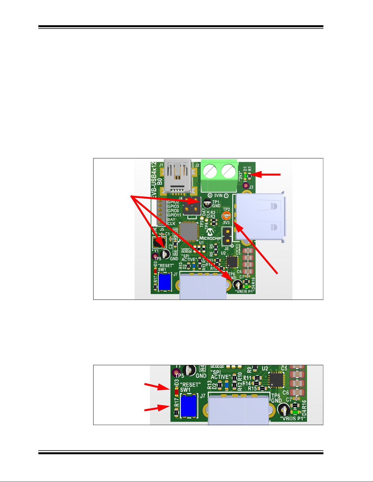
3.1.3 Board Power
The board includes LED indicators to indicate if all board power nets are working and
includes test loops for quick measurements. The location of these LEDs and test loops
are shown in Figure 3-2 below.
FIGURE 3-2: BOARD POWER LEDS AND TEST LOOPS)
GROUND
TEST
POINTS
TP1
TP5
TP6
3.3V LED
INDICATOR
D1
3.3V
TEST
POINT
TP2
3.1.4 Reset
An on-board reset button (SW1) is included, and this resets the USB4712/USB4912
when pressed. A red LED indicator (D3) also illuminates when the reset signal is
asserted (active low). The locations of these components are shown in Figure 3-3
below.
FIGURE 3-3: RESET BUTTON LOCATION
RESET LED
D3
RESET BUTTON
SW1
DS50002889A-page 18 2019 Microchip Technology Inc.
Page 19

Hardware Configuration
3.1.5 USB Ports
The following is a list of capabilities for each USB port on the EVB-USB4x12.
• Port 0:
- Data upstream port (connects to a USB host)
- USB2.0 Mini-B receptacle
- USB2.0 data connectivity
• Port 1:
- Data downstream port with AutoFlex (USB4712) or multi-host endpoint reflec-
tor (USB4912)
- USB2.0 Type-A receptacle
- USB2.0 data connectivity
- BC1.2 charging at up to 7.5W (5V at 1.5A)
• Port 2:
- Downstream Type-A receptacle
- USB2.0 data connectivity
Figure 3-4 shows the top view of the EVB-USB4x12.
FIGURE 3-4: EVB-USB4X12 USB PORTS
PORT
0
PORT
PORT
1
3.1.6 Spare GPIOs
The EVB-USB4x12 includes 4 GPIOs for USB to GPIO or SMBus/I
use. These pins are connected to J5 1x6 header. See Figure 3-5.
2
2
C Slave to GPIO
2019 Microchip Technology Inc. DS50002889A-page 19
Page 20

EVB-USB4x12 Evaluation Board User’s Guide
FIGURE 3-5: SPARE GPIOS
SPARE GPIO
HEADER
J5
3.1.7 SMBus/I2C Slave
An SMBus/I2C slave interface is available to configure or retrieve status from the
USB4712/USB4912 hub. Pull-up resistors must be sensed by the hub at power on in
order for the SMBus/I
sensed as high upon power-on/reset, the SMBus/I
Figure 3-6.
FIGURE 3-6: USB TO SMBUS/I
2
C slave interface to be active. If both SDA and SCL are not
2
C SLAVE HEADER LOCATIONS
2
C slave interface is disabled. See
SLAVE DATA
(J5-5)
SLAVE CLOCK
(J5-6)
3.1.8 USB to SMBus/I2C Master
A USB to SMBus/I2C master interface is available to allow for the USB host to read or
write data to an attached SMBus/I
nected to the SMBus/I
2
C bus and is address 57h – 1010_111(r/w). An optional external
slave device may be attach to the board through fly wires by connected to TP3 (DAT)
and TP4 (CLK).
2
The USB to SMBus/I
C feature may be tested with the MPLAB Connect Configurator
tool, available from the Microchip website. See Figure 3-7.
2
C slave device. The on-board UCS2114 is con-
DS50002889A-page 20 2019 Microchip Technology Inc.
Page 21

Hardware Configuration
FIGURE 3-7: USB TO SMBUS/I2C MASTER HEADER LOCATIONS
MASTER
DATA
(TP3)
MASTER
CLOCK
(TP4)
UCS2114
(U2)
3.1.9 LED Indicators
Table 3-1 describes the LEDs included on the PCB.
TABLE 3-1: EVB-USB4X12 LED DESCRIPTIONS
Reference
Designator
D1 3V3 Illuminates when board 3.3V net is powered on
D2 SPI ACTIVE SPI Activity indicator LED. Illuminates when the SPI Chip
D3 RESET Reset indicator LED. Illuminates when the RESET_N signal is
D4 VBUS P1 Downstream Port 1 VBUS indicator. Illuminates when VBUS
Label Description
Enable signal is asserted (pulled low).
asserted (pulled low).
on Port 1 is present.
3.1.10 Switches
Table 3-2 shows the switches included on the PCB.
TABLE 3-2: EVB-USB4X12 SWITCH DESCRIPTIONS
Reference
Designator
SW1 RESET Hub reset push button
Label Description
2019 Microchip Technology Inc. DS50002889A-page 21
Page 22

EVB-USB4x12 Evaluation Board User’s Guide
3.1.11 Connector Descriptions
Table 3-3 specifies the connectors included on the PCB.
TABLE 3-3: EVB-USB4X12 CONNECTOR DESCRIPTIONS
Reference
Designator
J1 USB Mini-B
J2 2-Pin Terminal
J3 USB Type-A
J4 2x2 Header N/A Connects VBUS from upstream USB con-
J5 1x6 Header GPIO2,
J6 1x2 Header N/A Installs shunt to force the SPI Flash to
J7 USB Type-A
Type Label Description
N/A Upstream USB port
Receptacle
5 V
Block
N/A Downstream port 2 USB Type-A connector
Receptacle
GPIO3,
GPIO6,
GPIO11,
DAT, CLK
N/A Downstream Port 1 USB Type-A connector
Receptacle
Optional 5V board supply input
IN
(USB4912 only)
nector to board power. Install shunts across
pins [1-2] and [3-4] to operate the hub PCB
in bus-powered mode.
Header for probing GPIOs and I
interface
remain inactive
2
C slave
3.1.12 Test Points
Table 3-4 describes the test points included in the PCB.
TABLE 3-4: EVB-USB4X12 TEST POINT DESCRIPTIONS
Reference
Designator
TP1 GND Ground test point
TP2 3V3 3.3V board power test point
TP3 DAT I
TP4 n/a I
TP5 GND Ground test point
TP6 GND Ground test point
Label Description
2
C Master data test point
2
C Master clock test point
DS50002889A-page 22 2019 Microchip Technology Inc.
Page 23

EVB-USB4X12
EVALUATION BOARD
USER’S GUIDE
Appendix A. PCB Layers
A.1 INTRODUCTION
This appendix shows the EVB-USB4x12 Evaluation Board User’s Guide PCB Layers. See Figure A-1 to
Figure A-6.
FIGURE A-1: EVB-USB4X12 EVALUATION BOARD TOP SILKSCREEN
FIGURE A-2: EVB-USB4X12 EVALUATION BOARD TOP COPPER
2019 Microchip Technology Inc. DS50002889A-page 23
Page 24

EVB-USB4x12 Evaluation Board User’s Guide
FIGURE A-3: EVB-USB4X12 EVALUATION BOARD LAYER 2 (GROUND)
FIGURE A-4: EVB-USB4X12 EVALUATION BOARD LAYER 3 (POWER)
DS50002889A-page 24 2019 Microchip Technology Inc.
Page 25

PCB Layers
FIGURE A-5: EVB-USB4X12 EVALUATION BOARD BOTTOM COPPER
FIGURE A-6: EVB-USB4X12 EVALUATION BOARD BOTTOM SILKSCREEN
2019 Microchip Technology Inc. DS50002889A-page 25
Page 26

EVB-USB4x12 Evaluation Board User’s Guide
NOTES:
DS50002889A-page 26 2019 Microchip Technology Inc.
Page 27

EVB-USB4X12
EVALUATION BOARD
USER’S GUIDE
Appendix B. Schematics
B.1 INTRODUCTION
This appendix shows the EVB-USB4x12 Evaluation Board Schematics. See Figure B-1 to Figure B-4.
2019 Microchip Technology Inc. DS50002889A-page 27
Page 28

DS50002889A-page 28 2019 Microchip Technology Inc.
FIGURE B-1: EVB-USB4X12 EVALUATION BOARD SCHEMATIC 1
EVB-USB4x12 Evaluation Board User’s Guide
1
2
3
4
5
6
USB4x12 Evaluation Board
Table of Contents
A A
B B
DescriptionSheet
1
2
USB4927, SST26VF SPI Flash, MCP1825 3.3V LDO
3
UPD360, USB DS Port 1, MCP19119 HV Supply 1
4
UPD360, USB DS Port 2, MCP19119 HV Supply 2
5
UCS2113 Port Controller, USB DS Ports 3 and 4
mini-B
USB2.0
C C
USB4x12
Revision History
00A
Terminal Block
VBUS
Revision SummaryRevision Date
Initial release
5VIN
SPI
Flash
3.3V
MCP1825
Author
Arnaldo Cruz6/18/2018Table of Contents, Revision History, Block Diagram
Notes
1
All resist ors are 1% unles s specified otherwis e
2
Shunt jumperdef aultselections are marked with an asterisk [*].
USB2.0
D D
Type-A
VBUS VBUS
1
2
USB2.0
UCS2114
3
Type-A
4
Daisy Chain Port
(USB4912 Only)
Variant:
PN:
6
[No Variations]
UNG_8184
Designedwith
Altium.com
Microchip Technology, Inc.
USB/Network Group - UNG
Designer:
www.Microchip.com
Andrew Rogers
EVB-USB4x12- Evaluation Board
Description:
Table of Contents, Block Diagram
Page Title:
EVB-USB4x12
Project Name:
B14B0
Date:Size: Sheet of Rev
5
7/16/2018
Page 29

2019 Microchip Technology Inc. DS50002889A-page 29
1
1
2
2
3
3
4
4
5
5
6
6
D D
C C
B B
A A
Page Title:
Project Name:
USB4x12 Hub
EVB-USB4x12
PN:
UNG_8184
Description:
Date:Size: Sheet of Rev
B24B0
7/16/2018
Designer:
Andrew Rogers
EVB-USB4x12- Evaluation Board
Designed with
[No Variations]
Variant:
Altium.com
10k
R15
3V3
12k
1%
R26
XTALI
XTALO
0.1uF
C11
1V2
1uF
C13
RBIAS
200k
R29
3V3
10k
R14
10k
R16
3V3
100k
R18
100k
R17
SIO1
3V3
0.1uF
C12
SIO0
FCEn
1k
R19
SPI Flash Active
External Reset
BLUE
D2
RESET
3V3
0.1uF
C26
0.1uF
DNP
C25
10pF
C19
10pF
C20
VBUS_DET
1k
R37
0.1uF
C14
3V3
0.1uF
C17
0.1uF
C18
0.1uF
C16
0.1uF
C15
1uF
C22
0.1uF
C23
SPI_CLK
SIO3F
SIO2F
SIO2F
SIO3F
0.1uF
C21
120R
FB1
SPI_CEn/CFG_NON_REM
SPI_DI/CFG_BC_EN
Ports 1 BC Enabled
200k
DNP
R34
3V3
Port 1 Non-Rem
200k
R35
0R DNP
R20
0R
R21
0R DNP
R24
0R
R25
SPI_CE_N
3V3
Hold
3V3
USBP0_PSPI_DI
SIO0
USB_SEC_N
USB_SEC_P
0.1uF
C24
USBP1_N 3
USBP1_P 3
10k
R36
0R
R22
0R
R23
SIO2
SIO3
RST_N
CFG_NON_REM
CFG_BC_EN
USBP0_N 3
USBP0_P 3
VBUS_DET 3
USB_SEC_N 3
USB_SEC_P 3
Reset
BC/Non-Rem Straps
SPI Flash Option
VDDCR12
13
VDDIO33
7
VDDIO33
14
VDDIO33
19
VDDIO33
25
VDDIO33
30
VDDIO33
33
VDDPLLREF33
39
ePAD
41
TEST1
8
TEST2
9
TEST3
10
SPI_CLK/SQI_CLK
15
SPI_DO/SQI_D0
16
SPI_DI/SQI_D1/CFG_BC_EN
17
SPI_CE_N/CFG_NON_REM
18
SQI_D2
20
SQI_D3
21
XTALO
37
XTALI/CLK_IN
38
RESET_N
28
VSS
36
RBIAS
40
POWER
VBUS_DET
29
PRT_CTL1/OCS1
12
NC
11
USBH_DP0
34
USBH_DM0
35
USB_DP1
2
USB_DM1
3
USB_DP2
4
USB_DM2
5
SMB1_DAT
31
GPIO2
27
GPIO3
26
GPIO6
24
SMB2_DAT
23
SMB2_CLK
22
GPIO11
6
SMB1_CLK
32
NC
1
CLOCK
UTILITY
SPI_SQI UPSTREAM
DOWNSTREAM
DAISY CHAIN
MISC
U5
USB4912
USBP0_N
USBP1_N
USBP1_P
PRTCTL1 3
200k
DNP
R30
Port 1 Removable
Port 1 BC Disabled
4.7k
R32
4.7k
R33
4.7k
R31
3V3
SMB2_DAT 3
SMB2_CLK 3
USB to I2C
Master
1
2
3
4
5
6
HDR-1.27 Male 1x6
J5
0R
R270RR28
3V3
USB4712 Only
CE
1
SO/SIO1
2
WP/SIO2
3
VSS
4
SI/SIO0
5
SCK
6
HOLD/SIO3
7
VDD
8
SST26VF016B
U3
3V3
24
VCC
5
GND
3
VCC
GND
G
U7
74LVC1G14GW,125
421
3
SPST-NO
SW1
VDD
3
GND
1
RST
2
MIC803/2.93V
U6
24
VCC
5
GND
3
VCC
GND
G
U4
74LVC1G14GW,125
GPIO2
GPIO3
GPIO6
GPIO11
SMB1_DAT
SMB1_CLK
USB4x12 Hub
RED
D3
12
J4
25Mhz
Y1
FIGURE B-2: EVB-USB4X12 EVALUATION BOARD SCHEMATIC 2
Microchip Technology, Inc.
USB/Network Group - UNG
www.Microchip.com
Schematics
Page 30

DS50002889A-page 30 2019 Microchip Technology Inc.
1
1
2
2
3
3
4
4
5
5
6
6
D D
C C
B B
A A
Page Title:
Project Name:
USB Ports
EVB-USB4x12
PN:
UNG_8184
Description:
Date:Size: Sheet of Rev
B34B0
7/16/2018
Designer:
Andrew Rogers
EVB-USB4x12- Evaluation Board
Designedwith
Altium.com
USB Ports
3V3
330R
R3
"PORT3"
0.1uF
C3
USB-A Downstream Port 1
EARTH_P1
PORT1 VBUS
3V3
47uF
C1
1k
DNP
R1
1k
R4D1
0.1uF
C2
VBUS
1
GND
4
D-
2
D+
3
VBUS
G
D+
0
USB2.0 STD-A FEMALE
J1
USB-IF TID 60001133
EARTH_P1EARTH_P0
3V3
330R
R6
EARTH_P0
0.1uF
C5
200k
R5
100k
R2
2.2uF
C4
PORT0
Mini-B Upstream Port
VBUS
1
GND
4
D-
2
D+
3
VBUS
G
D-
0
USB2.0 STD-A FEMALE
J3
Daisy Chain Port (USB4912 Only)
USBP1_N2
USBP1_P2
USBP0_N 2
USBP0_P 2
VBUS_DET 2
USB_SEC_N2
USB_SEC_P2
PWR_EN1
1
GND
2
COMM_ILIM
3
VBUS1
4
VBUS1
5
VS210VS2
9
VDD
8
VS17VS1
6
VBUS2
12
VBUS2
11
BOOST
13
GND
14
PWR_EN2
15
ALERT2
16
GND17SMDATA18SMCLK
19
ALERT1
20
W
R_
EN1
N
CO
M_ILI
M
VBUS1VBUS1VBUS2
VBUS2
OOS
T
N
W
R_
N2
N
UCS2114-1-V/LX
U2
0R
R10
VBUS2
47uF
C7
47uF
C9
47uF
C8
47uF
C10
5V
0.1uF
C6
5V
10k
R8
5V
Configuration: 3.2A Limit per port
SMBus Enabled(connected to USB Hub)
VBUS1
0R
DNP
R7
33k 1%
R9
10k
R11
5V
VBUS2
PRTCTL12
VBUS1
Port Power Switch
VBUS_UP 4
VBUS_UP Can optionally supply power to the entire PCB.
See the "Voltage Regulators" sheet for the jumper option
to select between "VBUS_UP" power or external "VBAT" supply.
SMB2_DAT2
SMB2_CLK2
4.7k
R12
4.7k
R13
3V3
2 4
VCC
5
GND
3
VCC
GND
U1
74LVC1G14GW,125
ID
4
VBUS
1
GND
5
D-
2
D+
3
0
USB2.0 MINI-BFEMALE
J2
I2C Communicationto UCS2114 is optional and not required for normal operation
FIGURE B-3: EVB-USB4X12 EVALUATION BOARD SCHEMATIC 3
ND
EVB-USB4x12 Evaluation Board User’s Guide
B
M
ERT
ERT
E
ND
Microchip Technology, Inc.
USB/Network Group - UNG
www.Microchip.com
Page 31

2019 Microchip Technology Inc. DS50002889A-page 31
1
1
2
2
3
3
4
4
5
5
6
6
D D
C C
B B
A A
Page Title:
Project Name:
Voltage Regulator
EVB-USB4x12
PN:
UNG_8184
Description:
Date:Size: Sheet of Rev
B44B0
7/16/2018
Designer:
Andrew Rogers
EVB-USB4x12- Evaluation Board
Designed with
Altium.com
Fiducials
Voltage Input Select
Voltage Regulator
10k
R40
5V
3V3
1k
R38
3V3
3V3 @ 500mA
10uF
C28
FB3V3
10uF
C29
5VDC to 3.3VDC
3V3
GND
3V35V
86.6k
1%
R41
FID1 FID2 FID3
FID4 FID5 FID6
0.1uF
C30
D5
VIN
0.1uF
C27
20R
R39
TP1
TP2
2
1
J6
GND (TAB)
6
VIN2VOUT
4
GND
3
SHDN
1
ADJ
5
MCP1825/ADJ
U8
12k
1%
R42
SMBJP6KE6.8
D4
VBUS_UP Can optionally supply power to the entire PCB.
If used, ensure that the VBUS source has sufficient current
capacity to power the PCB + all connected downstream devices.
1 2
3 4
HDR-2.54 Male 2x2
J7
VBUS_UP3
FIGURE B-4: EVB-USB4X12 EVALUATION BOARD SCHEMATIC 4
Microchip Technology, Inc.
USB/Network Group - UNG
www.Microchip.com
Schematics
Page 32

EVB-USB4x12 Evaluation Board User’s Guide
NOTES:
DS50002889A-page 32 2019 Microchip Technology Inc.
Page 33

EVB-USB4X12
EVALUATION BOARD
USER’S GUIDE
Appendix C. Bill of Materials
C.1 INTRODUCTION
This appendix includes the EVB-USB4x12 Evaluation Board Bill of Materials (BOM). See Table C-1.
2019 Microchip Technology Inc. DS50002889A-page 33
Page 34

DS50002889A-page 34 2019 Microchip Technology Inc.
EVB-USB4x12 Evaluation Board User’s Guide
TABLE C-1: EVB-USB4X12 BILL OF MATERIALS
Item Quantity Designator Description Manufacturer Manufacturer Part Number
1 2 C1, C2 CAP CER 10 pF 50V 5% NP0 SMD 0402 Murata GRM1555C1H100JZ01D
2 5 C3, C4, C5, C6, C28 CAP CER 47 uF 6.3V 20% X5R SMD 0805 Taiyo Yuden JMK212BJ476MG-T
3 17 C7, C8, C9, C13, C14, C15, C17, C18, C20,
C21, C22, C23, C24, C25, C26, C29, C30
4 1 C10 CAP CER 2.2 uF 10V 10% X7R SMD 0603 Murata GRM188R71A225KE15D
5 2 C11, C12 CAP CER 10 uF 16V 10% X5R SMD 0805 Wurth Electronics Inc 885012107014
6 2 C16, C19 CAP CER 1 uF 6.3V 10% X5R SMD 0603 Panasonic ECJ-1VB0J105K
7 2 D1, D4 DIO LED GREEN 2V 30 mA 35 mcd Clear SMD 0603 Lite-On Inc LTST-C191KGKT
8 1 D2 DIO LED BLUE 2.8V 20 mA 15 mcd Clear SMD 0603 Lite-On LTST-C193TBKT-5A
9 1 D3 LED, Bright Red, 0603 Lite-On LTST-C19
10 1 D5 DIO TVS SMBJP6KE6.8CA 5.8V 600W
11 1 D6 DIO SCTKYARR BAT54C 530 mV 200 mA 30V
12 1 FB1 FERRITE 600 mA 120R SMD 0603 TDK Corporation MMZ1608B121CTAH0
13 1 J1 CON USB2.0 MINI-B FEMALE SMD R/A Wurth Electronics Inc. 65100516121
14 1 J2 CON TERMINAL 5.08 mm 1X2 Female 16-30AWG
15 2 J3, J7 CON USB2.
16 1 J4 CON HDR-2.54 Male 2x2 Gold 5.84MH TH VERT Wurth Electronics Inc 61300421121
17 1 J5 CON HDR-1.27 Male 1x6 Gold 3MH TH VERT Sullins GRPB061VWVN-RC
18 4 R1, R13, R16, R17 RES TKF 1k 1% 1/10W SMD 0603 Panasonic ERJ-3EKF1001V
19 8 R2, R3, R26, R27, R28, R39 RES TKF 0R 1/10W SMD 0603 NIC Components NRC06Z0TRF
20 1 R4 RES TKF 12k 1% 1/10W SMD 0603 Yageo RC0603FR-071
21 5 R6, R7, R8, R11, R14 RES TKF 4.7k 1% 1/10W SMD 0603 Panasonic ERJ-3EKF4701V
22 2 R9, R12 RES TKF 200k 1% 1/10W SMD 0603 Vishay CRCW0603200KFKEA
23 1 R15 RES TKF 0R 1/10W SMD 0603 Panasonic ERJ-3GSY0R00V
24 2 R18, R43 RES TKF 330R 1% 1/10W SMD 0603 Panasonic ERJ-3EKF3300V
25 1 R19 RES TKF 20R 1% 1/10W SMD 0603 Panasonic ERJ-3EKF20R0V
26 1 R22 RES TKF 12k 1% 1/10W SMD 0603 Stackpole Electronics Inc RMCF0603FT12K0
27 1 R23 RES TKF
CAP CER 0.1 uF 16V 10% X7R SMD 0402 Murata GRM155R71C104
Micro Commercial Co SMBJP6KE6.8CA-TP
DO-214AA_SMB
Diodes Incorporated BAT54CTA
SOT-23-3
TE Connectivity 282836-2
13.5A TH RA
0 STD-A FEMALE TH R/A TE Connectivity AMP Connectors 292303-1
86.6k 1% 1/10W SMD 0603 Panasonic Electronic Components ERJ-3EKF8662V
KA88D
1KRKT
2KL
Page 35

2019 Microchip Technology Inc. DS50002889A-page 35
TABLE C-1: EVB-USB4X12 BILL OF MATERIALS (CONTINUED)
Item Quantity Designator Description Manufacturer Manufacturer Part Number
28 4 R24, R25, R32, R33 RES TKF 10k 1% 1/10W SMD 0603 ROHM MCR03EZPFX1002
29 2 R30, R31 RES TF 100k 1% 1/8W SMD 0603 Vishay MCT06030C1003FP500
30 4 R34, R35, R36, R41 RES TKF 10k 1% 1/10W SMD 0603 Vishay CRCW060310K0FKEA
31 1 R42 RES TKF 33k 1% 1/10W SMD 0603 Panasonic ERJ-3EKF3302V
32 1 SW1 SWITCH TACT SPST 16V 50 mA PTS810 SJM 250
33 1 U1 IC INTERFACE USB4712/USB4912 US
34 1 U2 MCHP INTERFACE USB Power Controller UCS2114
35 1 U3 MCHP ANALOG LDO ADJ MCP1825T-ADJE/DC
36 1 U4 MCHP MEMORY SERIAL FLASH 16M 104 MHz
37 3 U5, U7, U8 74LVC1G1
38 1 U6 MCHP ANALOG SUPERVISOR 2.93V
39 1 Y1 Crystal 25 MHz 4 pins 3225 ABRACON ABM8G-25.000MHZ-B4Y-T
SMTR LFS SMD
B 2.0
Multi-Host Hub Controller VQFN-40
QFN-20
SOT-223-5
SST26VF016B-104I/SM SOIJ-8
4GW,125 SCHMITT-TRG INVERTER NXP 74LVC1G14GW,125
MIC803-29D4VM3-TR SOT-23-3
C&K Components PTS810 SJM 250 SMTR LFS
Microchip Technology USB4712-I/PNXVAA or USB4912-I/PNX-
VAA
Microchip Technology UCS2114-1-V/LX
Microchip Technology MCP1825T-ADJE/DC
Microchip Technology SST26VF016B-104I/SM
Microchip Technology MIC803-29D4VM3-TR
Bill of Materials
Page 36

EVB-USB4x12 Evaluation Board User’s Guide
NOTES:
DS50002889A-page 36 2019 Microchip Technology Inc.
Page 37

NOTES:
2019 Microchip Technology Inc. DS50002889A-page 37
Page 38

Worldwide Sales and Service
AMERICAS
Corporate Office
2355 West Chandler Blvd.
Chandler, AZ 85224-6199
Tel: 480-792-7200
Fax: 480-792-7277
Technical Support:
http://www.microchip.com/
support
Web Address:
www.microchip.com
Atlanta
Duluth, GA
Tel: 678-957-9614
Fax: 678-957-1455
Austin, TX
Tel: 512-257-3370
Boston
Westborough, MA
Tel: 774-760-0087
Fax: 774-760-0088
Chicago
Itasca, IL
Tel: 630-285-0071
Fax: 630-285-0075
Dallas
Addison, TX
Tel: 972-818-7423
Fax: 972-818-2924
Detroit
Novi, MI
Tel: 248-848-4000
Houston, TX
Tel: 281-894-5983
Indianapolis
Noblesville, IN
Tel: 317-773-8323
Fax: 317-773-5453
Tel: 317-536-2380
Los Angeles
Mission Viejo, CA
Tel: 949-462-9523
Fax: 949-462-9608
Tel: 951-273-7800
Raleigh, NC
Tel: 919-844-7510
New York, NY
Tel: 631-435-6000
San Jose, CA
Tel: 408-735-9110
Tel: 408-436-4270
Canada - Toronto
Tel: 905-695-1980
Fax: 905-695-2078
ASIA/PACIFIC
Australia - Sydney
Tel: 61-2-9868-6733
China - Beijing
Tel: 86-10-8569-7000
China - Chengdu
Tel: 86-28-8665-5511
China - Chongqing
Tel: 86-23-8980-9588
China - Dongguan
Tel: 86-769-8702-9880
China - Guangzhou
Tel: 86-20-8755-8029
China - Hangzhou
Tel: 86-571-8792-8115
China - Hong Kong SAR
Tel: 852-2943-5100
China - Nanjing
Tel: 86-25-8473-2460
China - Qingdao
Tel: 86-532-8502-7355
China - Shanghai
Tel: 86-21-3326-8000
China - Shenyang
Tel: 86-24-2334-2829
China - Shenzhen
Tel: 86-755-8864-2200
China - Suzhou
Tel: 86-186-6233-1526
China - Wuhan
Tel: 86-27-5980-5300
China - Xian
Tel: 86-29-8833-7252
China - Xiamen
Tel: 86-592-2388138
China - Zhuhai
Tel: 86-756-3210040
ASIA/PACIFIC
India - Bangalore
Tel: 91-80-3090-4444
India - New Delhi
Tel: 91-11-4160-8631
India - Pune
Tel: 91-20-4121-0141
Japan - Osaka
Tel: 81-6-6152-7160
Japan - Tokyo
Tel: 81-3-6880- 3770
Korea - Daegu
Tel: 82-53-744-4301
Korea - Seoul
Tel: 82-2-554-7200
Malaysia - Kuala Lumpur
Tel: 60-3-7651-7906
Malaysia - Penang
Tel: 60-4-227-8870
Philippines - Manila
Tel: 63-2-634-9065
Singapore
Tel: 65-6334-8870
Taiwan - Hsin Chu
Tel: 886-3-577-8366
Taiwan - Kaohsiung
Tel: 886-7-213-7830
Taiwan - Taipei
Tel: 886-2-2508-8600
Thailand - Bangkok
Tel: 66-2-694-1351
Vietnam - Ho Chi Minh
Tel: 84-28-5448-2100
EUROPE
Austria - Wels
Tel: 43-7242-2244-39
Fax: 43-7242-2244-393
Denmark - Copenhagen
Tel: 45-4450-2828
Fax: 45-4485-2829
Finland - Espoo
Tel: 358-9-4520-820
France - Paris
Tel: 33-1-69-53-63-20
Fax: 33-1-69-30-90-79
Germany - Garching
Tel: 49-8931-9700
Germany - Haan
Tel: 49-2129-3766400
Germany - Heilbronn
Tel: 49-7131-72400
Germany - Karlsruhe
Tel: 49-721-625370
Germany - Munich
Tel: 49-89-627-144-0
Fax: 49-89-627-144-44
Germany - Rosenheim
Tel: 49-8031-354-560
Israel - Ra’anana
Tel: 972-9-744-7705
Italy - Milan
Tel: 39-0331-742611
Fax: 39-0331-466781
Italy - Padova
Tel: 39-049-7625286
Netherlands - Drunen
Tel: 31-416-690399
Fax: 31-416-690340
Norway - Trondheim
Tel: 47-7288-4388
Poland - Warsaw
Tel: 48-22-3325737
Romania - Bucharest
Tel: 40-21-407-87-50
Spain - Madrid
Tel: 34-91-708-08-90
Fax: 34-91-708-08-91
Sweden - Gothenberg
Tel: 46-31-704-60-40
Sweden - Stockholm
Tel: 46-8-5090-4654
UK - Wokingham
Tel: 44-118-921-5800
Fax: 44-118-921-5820
DS50002889A-page 38 2019 Microchip Technology Inc.
05/14/19
 Loading...