

Page 1

EVB-USB4715
Evaluation Kit
User’s Guide
2017 Microchip Technology Inc. DS50002679A
Page 2

Note the following details of the code protection feature on Microchip devices:
YSTEM
CERTIFIE DBYDNV
== ISO/TS16949==
• Microchip products meet the specification contained in their particular Microchip Data Sheet.
• Microchip believes that its family of products is one of the most secure families of its kind on the market today, when used in the
intended manner and under normal conditions.
• There are dishonest and possibly illegal methods used to breach the code protection feature. All of these methods, to our
knowledge, require using the Microchip products in a manner outside the operating specifications contained in Microchip’s Data
Sheets. Most likely, the person doing so is engaged in theft of intellectual property.
• Microchip is willing to work with the customer who is concerned about the integrity of their code.
• Neither Microchip nor any other semiconductor manufacturer can guarantee the security of their code. Code protection does not
mean that we are guaranteeing the product as “unbreakable.”
Code protection is constantly evolving. We at Microchip are committed to continuously improving the code protection features of our
products. Attempts to break Microchip’s code protection feature may be a violation of the Digital Millennium Copyright Act. If such acts
allow unauthorized access to your software or other copyrighted work, you may have a right to sue for relief under that Act.
Information contained in this publication regarding device applications and the like is provided only for your convenience and may be
superseded by updates. It is your responsibility to ensure that your application meets with your specifications. MICROCHIP MAKES NO
REPRESENTATIONS OR WARRANTIES OF ANY KIND WHETHER EXPRESS OR IMPLIED, WRITTEN OR ORAL, STATUTORY OR
OTHERWISE, RELATED TO THE INFORMATION, INCLUDING BUT NOT LIMITED TO ITS CONDITION, QUALITY, PERFORMANCE,
MERCHANTABILITY OR FITNESS FOR PURPOSE. Microchip disclaims all liability arising from this information and its use. Use of Microchip devices in life support and/or safety applications is entirely at the buyer’s risk, and the buyer agrees to defend, indemnify and hold
harmless Microchip from any and all damages, claims, suits, or expenses resulting from such use. No licenses are conveyed, implicitly or
otherwise, under any Microchip intellectual property rights unless otherwise stated.
Trademarks
The Microchip name and logo, the Microchip logo, AnyRate, AVR, AVR logo, AVR Freaks, BeaconThings, BitCloud, CryptoMemory, CryptoRF,
dsPIC, FlashFlex, flexPWR, Heldo, JukeBlox, KEELOQ, KEELOQ logo, Kleer, LANCheck, LINK MD, maXStylus, maXTouch, MediaLB, megaAVR,
MOST, MOST logo, MPLAB, OptoLyzer, PIC, picoPower, PICSTART, PIC32 logo, Prochip Designer, QTouch, RightTouch, SAM-BA, SpyNIC,
SST, SST Logo, SuperFlash, tinyAVR, UNI/O, and XMEGA are registered trademarks of Microchip Technology Incorporated in the U.S.A. and
other countries.
ClockWorks, The Embedded Control Solutions Company, EtherSynch, Hyper Speed Control, HyperLight Load, IntelliMOS, mTouch, Precision
Edge, and Quiet-Wire are registered trademarks of Microchip Technology Incorporated in the U.S.A.
Adjacent Key Suppression, AKS, Analog-for-the-Digital Age, Any Capacitor, AnyIn, AnyOut, BodyCom, chipKIT, chipKIT logo, CodeGuard,
CryptoAuthentication, CryptoCompanion, CryptoController, dsPICDEM, dsPICDEM.net, Dynamic Average Matching, DAM, ECAN,
EtherGREEN, In-Circuit Serial Programming, ICSP, Inter-Chip Connectivity, JitterBlocker, KleerNet, KleerNet logo, Mindi, MiWi, motorBench,
MPASM, MPF, MPLAB Certified logo, MPLIB, MPLINK, MultiTRAK, NetDetach, Omniscient Code Generation, PICDEM, PICDEM.net, PICkit,
PICtail, PureSilicon, QMatrix, RightTouch logo, REAL ICE, Ripple Blocker, SAM-ICE, Serial Quad I/O, SMART-I.S., SQI, SuperSwitcher,
SuperSwitcher II, Total Endurance, TSHARC, USBCheck, VariSense, ViewSpan, WiperLock, Wireless DNA, and ZENA are trademarks of
Microchip Technology Incorporated in the U.S.A. and other countries.
SQTP is a service mark of Microchip Technology Incorporated in the U.S.A.
Silicon Storage Technology is a registered trademark of Microchip Technology Inc. in other countries.
GestIC is a registered trademark of Microchip Technology Germany II GmbH & Co. KG, a subsidiary of Microchip Technology Inc., in other
countries.
All other trademarks mentioned herein are property of their respective companies.
© 2017, Microchip Technology Incorporated, All Rights Reserved.
ISBN: 9781522421832
QUALITYMANAGEMENTS
DS50002679A-page 2 2017 Microchip Technology Inc.
Microchip received ISO/TS-16949:2009 certification for its worldwide
headquarters, design and wafer fabrication facilities in Chandler and
Tempe, Arizona; Gresham, Oregon and design centers in California
and India. The Company’s quality system processes and procedures
are for its PIC
devices, Serial EEPROMs, microperipherals, nonvolatile memory and
analog products. In addition, Microchip’s quality system for the design
and manufacture of development systems is ISO 9001:2000 certified.
®
MCUs and dsPIC® DSCs, KEELOQ
®
code hopping
Page 3

EU Declaration of Conformity
This declaration of conformity is issued by the manufacturer.
The development/evaluation tool is designed to be used for research and development in a laboratory environment. This
development/evaluation tool is not a Finished Appliance, nor is it intended for incorporation into Finished Appliances that are
made commercially available as single functional units to end users under EU EMC Directive 2004/108/EC and as supported by
the European Commission's Guide for the EMC Directive 2004/108/EC (8th February 2010).
This development/evaluation tool complies with EU RoHS2 Directive 2011/65/EU.
This development/evaluation tool, when incorporating wireless and radio-telecom functionality, is in compliance with the
essential requirement and other relevant provisions of the R&TTE Directive 1999/5/EC and the FCC rules as stated in the
declaration of conformity provided in the module datasheet and the module product page available at www.microchip.com.
For information regarding the exclusive, limited warranties applicable to Microchip products, please see Microchip’s standard
terms and conditions of sale, which are printed on our sales documentation and available at www.microchip.com.
Signed for and on behalf of Microchip Technology Inc. at Chandler, Arizona, USA.
Object of Declaration: EVB-USB4715
2017 Microchip Technology Inc. DS50002679A-page 3
Page 4

EVB-USB5807/6 Evaluation Kit User’s Guide
NOTES:
DS50002679A-page 4 2017 Microchip Technology Inc.
Page 5

EVB-USB4715
EVALUATION KIT
USER’S GUIDE
Table of Contents
Preface ........................................................................................................................... 7
Introduction............................................................................................................ 7
Document Layout .................................................................................................. 7
Conventions Used In This Guide........................................................................... 8
Warranty Registration............................................................................................ 9
The Microchip Web Site ........................................................................................ 9
Customer Support ................................................................................................. 9
Document Revision History ................................................................................... 9
Chapter 1. Overview
1.1 EVB-USB4715 Overview .............................................................................. 11
1.2 Features ....................................................................................................... 11
1.3 Block Diagram .............................................................................................. 12
1.4 References ................................................................................................... 12
1.5 Definitions ..................................................................................................... 13
Chapter 2. Getting Started
2.1 Contents of the Kit ........................................................................................ 14
2.2 Getting Started ............................................................................................. 14
2.2.1 Quick Start ................................................................................................. 14
Chapter 3. Hardware Configuration
3.1 Hardware Configuration Options .................................................................. 15
3.1.1 Configuration ............................................................................................. 15
3.1.2 Power Source - Self Powered ................................................................... 17
3.1.3 Downstream Port Power Control ............................................................... 17
3.1.4 USB Type-C Ports ..................................................................................... 17
3.1.5 LED Indicators on EVB-USB4715 ............................................................. 17
3.1.6 Switches on EVB-USB4715 ...................................................................... 18
3.1.7 Connector Descriptions for EVB-USB4715 ............................................... 18
3.1.8 Test Points on USB4715 ........................................................................... 19
Appendix A. Schematics
A.1 Introduction .................................................................................................. 20
Appendix B. EVB-USB4715 BOM
B.1 Introduction .................................................................................................. 27
Appendix C. EVB-USB4715 PCB Silk Screens
C.1 Introduction .................................................................................................. 30
Worldwide Sales and Service .................................................................................... 32
2017 Microchip Technology Inc. DS50002679A-page 5
Page 6

EVB-USB4715 Evaluation Kit User’s Guide
NOTES:
DS50002679A-page 6 2017 Microchip Technology Inc.
Page 7

EVB-USB4715
EVALUATION KIT
USER’S GUIDE
Preface
NOTICE TO CUSTOMERS
All documentation becomes dated, and this manual is no exception. Microchip tools and
documentation are constantly evolving to meet customer needs, so some actual dialogs
and/or tool descriptions may differ from those in this document. Please refer to our web site
(www.microchip.com) to obtain the latest documentation available.
Documents are identified with a “DS” number. This number is located on the bottom of each
page, in front of the page number. The numbering convention for the DS number is
“DSXXXXXA”, where “XXXXX” is the document number and “A” is the revision level of the
document.
For the most up-to-date information on development tools, see the MPLAB
Select the Help menu, and then Topics to open a list of available online help files.
®
IDE online help.
INTRODUCTION
This chapter contains general information that will be useful to know before using the
EVB-USB4715. Items discussed in this chapter include:
• Document Layout
• Conventions Used In This Guide
• Warranty Registration
• The Microchip Web Site
• Customer Support
• Document Revision History
DOCUMENT LAYOUT
This document describes how to use the EVB-USB4715 as a demonstration platform
optimized for portable applications. The manual layout is as follows:
• Chapter 1. “Overview” – Shows a brief description of the EVB-USB4715
• Chapter 2. “Getting Started” – Provides information about set-up and operation
of the EVB-USB4715.
• Chapter 3. “Hardware Configuration” – Includes information about the
hardware configuration of the EVB-USB4715.
• Appendix A. “Schematics”
• Appendix B. “EVB-USB4715 BOM”
• Appendix C. “EVB-USB4715 PCB Silk Screens”
2017 Microchip Technology Inc. DS50002679A-page 7
Page 8

EVB-USB4715 Evaluation Kit User’s Guide
CONVENTIONS USED IN THIS GUIDE
This manual uses the following documentation conventions:
DOCUMENTATION CONVENTIONS
Description Represents Examples
Arial font:
Italic characters Referenced books MPLAB® IDE User’s Guide
Emphasized text ...is the only compiler...
Initial caps A window the Output window
A dialog the Settings dialog
A menu selection select Enable Programmer
Quotes A field name in a window or
dialog
Underlined, italic text with
right angle bracket
Bold characters A dialog button Click OK
N‘Rnnnn A number in verilog format,
Text in angle brackets < > A key on the keyboard Press <Enter>, <F1>
Courier New font:
Plain Courier New Sample source code #define START
Italic Courier New A variable argument file.o, where file can be
Square brackets [ ] Optional arguments mcc18 [options] file
Curly brackets and pipe
character: { | }
Ellipses... Replaces repeated text var_name [,
A menu path File>Save
A tab Click the Power tab
where N is the total number of
digits, R is the radix and n is a
digit.
Filenames autoexec.bat
File paths c:\mcc18\h
Keywords _asm, _endasm, static
Command-line options -Opa+, -Opa-
Bit values 0, 1
Constants 0xFF, ‘A’
Choice of mutually exclusive
arguments; an OR selection
Represents code supplied by
user
“Save project before build”
4‘b0010, 2‘hF1
any valid filename
[options]
errorlevel {0|1}
var_name...]
void main (void)
{ ...
}
DS50002679A-page 8 2017 Microchip Technology Inc.
Page 9

WARRANTY REGISTRATION
Please complete the enclosed Warranty Registration Card and mail it promptly.
Sending the Warranty Registration Card entitles users to receive new product updates.
Interim software releases are available at the Microchip web site.
THE MICROCHIP WEB SITE
Microchip provides online support via our web site at www.microchip.com. This web
site is used as a means to make files and information easily available to customers.
Accessible by using your favorite Internet browser, the web site contains the following
information:
• Product Support – Data sheets and errata, application notes and sample
programs, design resources, user’s guides and hardware support documents,
latest software releases and archived software
• General Technical Support – Frequently Asked Questions (FAQs), technical
support requests, online discussion groups, Microchip consultant program
member listing
• Business of Microchip – Product selector and ordering guides, latest Microchip
press releases, listing of seminars and events, listings of Microchip sales offices,
distributors and factory representatives
Preface
CUSTOMER SUPPORT
Users of Microchip products can receive assistance through several channels:
• Distributor or Representative
• Local Sales Office
• Field Application Engineer (FAE)
• Technical Support
Customers should contact their distributor, representative or field application engineer
(FAE) for support. Local sales offices are also available to help customers. A listing of
sales offices and locations is included in the back of this document.
Technical support is available through the web site at:
http://www.microchip.com/support
DOCUMENT REVISION HISTORY
Revision A (October 2017)
• Initial Release of this Document.
2017 Microchip Technology Inc. DS50002679A-page 9
Page 10

EVB-USB4715 Evaluation Kit User’s Guide
NOTES:
DS50002679A-page 10 2017 Microchip Technology Inc.
Page 11

Chapter 1. Overview
1.1 EVB-USB4715 OVERVIEW
The EVB-USB4715 is a demonstration and evaluation platform that provides the necessary requirements and interface options for evaluating the USB4715, a 4-Port HS
USB Smart Hub on a 4-layer RoHS-compliant Printed Circuit Board (PCB). This will
allow the user to gain an understanding of the product and accelerate the integration
of the USB4715 into the user’s design. The USB4715 is compliant with USB 2.0
High-Speed (HS), Full-Speed (FS), and Low-Speed (LS) USB signaling. The evaluation
platform supports four downstream ports; two USB 2.0 ports with Type-C™ connectors
and two standard Type-A USB 2.0 ports. The EVB-USB4715 platform also supports
battery charging on all four ports (maximum of 10A* at any one time). The
EVB-USB4715 is configured for operation through internal default settings and supports custom configurations through SMBus or through the external 16-Mbit SPI Flash
device. The EVB-USB4715 supports FlexConnect role reversal for any of the four
downstream ports with the upstream port. The EVB-USB4715 demonstrates driver
compatibility with Microsoft
Mac OS
See Section 1.2 “Features” for more information.
®
X 10.4+, and Linux® hub drivers.
EVB-USB4715
EVALUATION KIT
USER’S GUIDE
®
Windows® 10, Windows 8.x, Windows 7, Windows XP,
1.2 FEATURES
• Microchip’s PortSwap, PHYBoostTM, and VariSenseTM technologies.
• USB4715 in a 48-pin QFN RoHS compliant package.
• USB 2.0 compliant (HS, FS, and LS operation).
• USB pins are 5 V tolerant.
• Self powered operation.
• USB USB 2.0 micro-AB upstream port.
• Four Downstream USB ports:
• All downstream ports support individual port power and overcurrent sense.
• All downstream ports can be enabled for battery charging with the battery
• Onboard SPI Flash for external downloadable firmware.
• Operates from a single voltage (+12.0 V, regulated) external power supply.
• Onboard 25 MHz crystal or external clock input.
• Single onboard +5.2 V, 10 Amp regulator.
• Single onboard +3.3 V, 0.5 Amp regulator.
• Port Power LED indicators.
• Port Connection indicators (in CONFIG3).
• SPI Flash activity blue LED indicator.
• Reset red LED indicator.
Note: *Requires a 12V, 85W supply.
- Two Type-C USB 2.0 downstream ports.
- Two Type-A USB 2.0-Only downstream ports.
charging select shunts J1 and J20 (BC1.2 or SE1, 2.1A max per port).
2017 Microchip Technology Inc. DS50002679A-page 11
Page 12
EVB-USB4715 Evaluation Kit User’s Guide
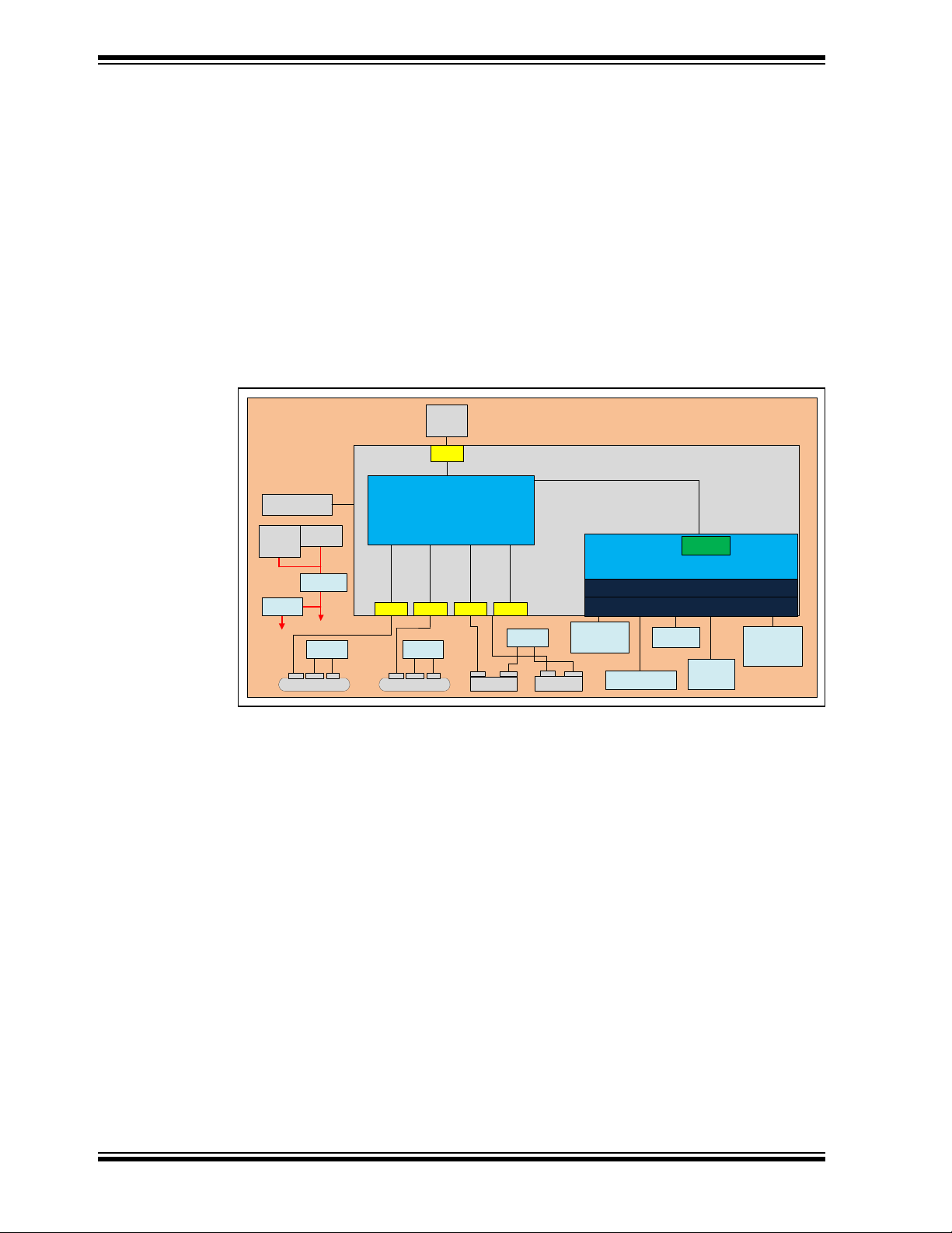
DC Jack
12V
UPD360
USB2- A P4
USB-C P1
USB CCxVBUS
USB-C P2
USB CCxVBUS
1.5A/3A
2.1A
2.1A
SST2 6VF016 B
SPI Flash
5V
3.3V
MCP1825
SANDIA
EVB-USB4715
USB2-A P3
mikr oBUS
Socket, GPI O,
LEDs
SMBus headers
(2)
USB VBUS
UCS211x
USB
VBUS
MIC24055
24LC02B
EEPRO M
I2S/Codec/
Audio
connect
USB2
Port0
Flex Port2 Flex Port4Flex Port 3Flex Port1
Flex Hub Controller Logic
(5 Downstream Ports)
USB4715
OTP
I/O Multiplexer
GPIO /I2C/I2 S/SPI /UART
MIPS Microcontroller
Terminal
Block
12V
Config Straps
1.5A/3A
USB2
Micro-B
Socket
UPD360
• Green LED indicators for 3.3V supply.
• Terminal block connector for use with an external bench supply.
• Barrel connector for use with a Microchip 12V power supply.
• Removable/non-removable downstream ports can be configured with select shunt
J1 and J21.
• Bridge peripheral functions:
- USB-to-UART (CDC)
- USB-to-I
2
S Audio Codec
- USB-to-SMBus
- USB-to-SPI
1.3 BLOCK DIAGRAM
FIGURE 1-1: USB4715 BLOCK DIAGRAM
1.4 REFERENCES
DS50002679A-page 12 2017 Microchip Technology Inc.
• Microchip, USB4715 Datasheet. DS00002514A
• USB-IF, Battery Charging Specification. Revision 1.2. December 7, 2010
• USB-IF, Type-C Cable and Connector Specification. Revision 1.1. April 3, 2015
Page 13

1.5 DEFINITIONS
• BC1.2 - Latest USB-IF specified USB battery charging standard
• CDP - Charging Downstream Port. A BC1.2 compliant port allows simultaneous
USB data and USB charging.
• DCP - Dedicated Charging Port. A BC1.2 compliant port which is only capable of
USB charging (no data).
• DFP - Downstream Facing Port
• EVB - Evaluation Board
•HS - USB 2.0 High-Speed
• OTP - One Time Programmable Memory
• SDP - Standard Downstream Port. A standard USB port with no high-current bat-
tery charging capabilities.
• SE1 - Type of Battery Charging (non-USB compliant) which sets the USB D+/D- to
specific DC voltages to communicate charging capability
• Type-C - Reversible USB Connector
• UFP - Upstream Facing Port
• USB-IF - USB Integrators Forum. Collection of corporate sponsored members
responsible for developing USB specifications.
2017 Microchip Technology Inc. DS50002679A-page 13
Page 14

Chapter 2. Getting Started
2.1 CONTENTS OF THE KIT
The EVB-USB4715 evaluation kit includes the basic equipment necessary for evaluation. The items included in the kit are:
1. EVB-USB4715 Evaluation Board
2. 12V Power Supply
3. USB cable, A to micro-B
2.2 GETTING STARTED
The Microchip EVB-USB4715 is designed for flexible configuration solutions. It can be
configured via default internal register settings, downloadable external firmware to an
onboard SPI Flash, through SMBus, or through the onboard configuration switches.
Microchip provides a comprehensive software programming tool, MPLAB® Connect,
for configuring USB4715 functions, registers, and OTP memory. When configured with
the default internal register settings, the device operates as a USB 2.0 hub with 4 USB
ports and Microchip’s standard VID/PID/DID settings. For additional information on the
MPLAB Connect programming tool, refer to Software Libraries within Microchip
USB4715 product page at www.microchip.com/USB4715
EVB-USB4715
EVALUATION KIT
USER’S GUIDE
2.2.1 Quick Start
To quickly start using the board, perform the following steps:
1. Connect the included 12V power supply to barrel connector on the
EVB-USB4715 (J11).
2. Using a USB Type-A plug to USB micro-B plug cable, connect the
EVB-USB4715 to a USB host via the upstream “Port 0” USB micro-B socket (J4).
3. You may now connect devices to any of the downstream ports to enumerate and
use those devices with the USB host.
4. Connect a shunt to jumper “VBUS_DET” (J4).
5. Slide the “ON/OFF” switch (SW2) to “ON”.
6. You can perform additional configuration or evaluate specific features by launching the MPLAB Connect software on your USB host or by manipulating the
included hardware configuration options detailed in the next section.
2017 Microchip Technology Inc. DS50002679A-page 14
Page 15

Chapter 3. Hardware Configuration
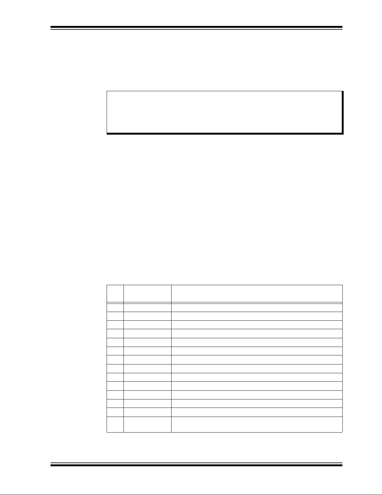
3.1 HARDWARE CONFIGURATION OPTIONS
FIGURE 3-1: EVB-USB4715 REV B (TOP-SIDE)
EVB-USB4715
EVALUATION KIT
USER’S GUIDE
3.1.1 Configuration
3.1.1.1 EXTERNAL SPI FLASH
Upon power-up, the USB4715 first looks for an external SPI ROM device and a valid
signature in the Flash. If one is found, the external ROM is enabled and code execution
is initiated from the external SPI ROM device.
To select the SPI device, install a shunt to short J18. Install shunts to pins 2-3 and 5-6
of J1. When code is executing from a SPI ROM device, a blue LED (D18) will illuminate.
Note: CFG_BC and CFG_Non-Rem options are deselected when a shunt is
installed on J1. When operating in SPI mode, all configuration is handled
by the code executing from the SPI ROM device.
Note: If the SPI Flash is not properly programmed or has an invalid signature, the
USB4715 will revert to internal defaults even if the SPI ROM is selected.
2017 Microchip Technology Inc. DS50002679A-page 15
Page 16

EVB-USB4715 Evaluation Kit User’s Guide
3.1.1.2 SMBUS2
If a SPI Flash device is not found, the firmware checks if SMBus2 is enabled.
To select SMBus2 configuration, leave J18 open to disconnect the SPI ROM and select
the CONFIG5 option from the CFG_STRAP header by shunting pins 9-10 of J2. Connect the SMBus2 pull-up resistors by connecting a shunt to J15 pins 1-2. The SMBus2
signals may be accessed at J14, pins 1 and 3 (pin2 is ground).
If CONFIG5 is selected and SMBus2 is enabled (that is, SMBus2 clock and data are
pulled up), the USB4715 will wait indefinitely for data from the SMBus2 interface and
will not enumerate to the USB host until the special USB_ATTACH command is sent.
3.1.1.3 INTERNAL DEFAULT CONFIGURATIONS WITH STRAPPING OPTIONS
When the USB4715 does not detect a valid SPI Flash image or SMBus2 configuration
upon power-up, the USB4715 uses internal default register settings. It also sets the
Vendor ID, Product ID, Language ID, and Device ID, and additional settings from internal ROM code.
If configuration is not done through SPI or SMBus2, additional configuration is available
through two hardware straps: CFG_BC_EN and CFG_NON-REM. The controls are
configured by selecting one of six resistor values for each pin. The EVB-USB4715
demonstrates two of the six possible resistor values for each of CFG_BC_EN and
CFG_NON-REM. These straps are read by the USB4715 device at power-on to determine the default configuration of the device.
To select the CFG_BC_EN and CFG_NON-REM modes, shunts must be connected to
J20 and J21 headers.
To use the battery charging options, connect a shunt to pins 4-5 of J1. For NON_REM
options, connect a shunt to pins 1-2 of J1. Select the desired CFG_BC_EN option by
connecting a shunt to J20. Select the desired CFG_NON-REM option by connecting a
shunt to J21.
TABLE 3-1: BATTERY CHARGING OPTIONS (CFG_BC_EN - J20)
Shunt Position Configuration
1-2 Ports 1-4 are BC1.2 enabled
2-3 Port 1 is BC1.2 enabled
TABLE 3-2: NON-REMOVABLE PORT OPTIONS (CFG_NON-REM - J21)
Shunt Position Configuration
1-2 All ports are removable
2-3 Port 1 is non-removable
DS50002679A-page 16 2017 Microchip Technology Inc.
Page 17
3.1.2 Power Source - Self Powered
The EVB-USB4715 only supports self-powered operation, and is powered through one
+12.0V regulated 'wall wart' external power supply. The power supply plugs into the 2.5
mm connector J11 on the board. Alternatively, an external voltage can be supplied to
the screw terminal TERM_BLOCK_2P (J12). The +12.0V feeds a 10A regulator which
outputs +5.2V to devices on the board and also supplies the +3.3V regulator.
Note: The supplied 12.0V external power supply cannot support simultaneous
battery charging on all downstream ports. Use a higher power supply if the
required test use case exceeds the power capability of the supply. Failure
to heed to this warning could result in damage to the 12.0V external power
supply.
3.1.3 Downstream Port Power Control
USB power to the four downstream ports is controlled via port power controllers with
auto-discharge function.
The two downstream Type-C ports are capable of up to 3A of USB Type-C battery
charging. Downstream port 1 is configured for 3A charging by default. The two downstream USB Type-A ports are capable of up to 2.1A of USB battery charging.
3.1.4 USB Type-C Ports
The EVB-USB4715 has two Type-C ports. These are USB 2.0 HS ports. The USB
Type-C ports utilize the Microchip UPD360 Type-C port controller in order to detect
USB Type-C attachment and plug orientation. The UPD360 monitors the voltage on the
USB Type-C CC wires in order to detect USB Type-C attach events. The downstream
ports 1 and 2 use UPD360s configured for 3A operation by default.
3.1.5 LED Indicators on EVB-USB4715
Ta bl e 3- 3 describes the LED indicators included on the EVB-USB4715.
TABLE 3-3: LED INDICATOR DESCRIPTIONS
REF.
DES.
D1 “C’nct3” PORT3 is connected (enumerated)
LABEL DESCRIPTION
D2 “C’nct2” PORT2 is connected (enumerated)
D3 “C’nct1” PORT1 is connected (enumerated)
D4 “C’nct4” PORT4 is connected (enumerated)
D5 “RESET” The RST_N signal is asserted.
D6 “PORT0 VBUS” Illuminates when 5V to upstream PORT0 VBUS is present.
D7 “PORT3 VBUS” Illuminates when 5V to upstream PORT3 VBUS is present.
D8 “PORT4 VBUS” Illuminates when 5V to upstream PORT4 VBUS is present.
D9 “PORT1 VBUS” Illuminates when 5V to upstream PORT1 VBUS is present.
D11 “ATTACH1” Illuminates when a device is detected by CC signals on PORT1.
D12 “PORT2 VBUS” Illuminates when 5V to upstream PORT2 VBUS is present.
D14 “ATTACH2” Illuminates when a device is detected by CC signals on PORT2.
D17 “3V3” Indicates 3.3V is present from the 3.3V voltage regulator.
D18 “SPI Flash
Active”
Indicates SPI Flash Memory activity.
2017 Microchip Technology Inc. DS50002679A-page 17
Page 18

EVB-USB4715 Evaluation Kit User’s Guide
3.1.6 Switches on EVB-USB4715
Ta bl e 3- 4 describes the switches included on the EVB-USB4715.
TABLE 3-4: SWITCH DESCRIPTIONS
REF. DES. LABEL DESCRIPTION
SW1 “RESET” Momentary push-button switch to assert RST_N.
SW2 “ON/OFF” Connects or disconnects the 12VDC supply
SW3 “OSC/I2S” Selects the clock source for the audio codec. The default
selection is 12S.
3.1.7 Connector Descriptions for EVB-USB4715
Ta bl e 3- 5 describes the connectors included on the PCB.
TABLE 3-5: USB4715 CONNECTOR DESCRIPTIONS
REF. DES. TYPE LABEL DESCRIPTION
J1 2x3 Header “SPI_DI/CFG
_BC_EN”
“SPI_CEn/CF
G_NON_RE
M”
Selects the between SPI memory capability
and BC/NON_REM capability.
For SPI, connect pins 2-3, 5-6.
For BC, connect pins 4-5.
For NON_REM, connect pins 1-2.
J2 2x6 Header “CFG_STRA
J3 2x1 Header “Ext.Reset” Connection for an external reset switch.
J4 USB2
Micro-AB
Connector
J5 1x2 Header “VBUS_DET” Connects VBUS from host to VBUS_DET
J7 USB2 Type-A
Connector
J8 USB2 Type-A
Connector
J9 USB Type-C
Connector
J10 USB Type-C
Connector
J11 Barrel Jack “12VDC” 12 VDC supply connection (center pin posi-
J12 2-pin terminal
block
J13 Audio Jack,
3.5mm
J14 2x2 Header “SMB2” Connection for SMBus2 (slave)
J15 1x2 Header “SMB2 PU” Connects the pull-up resistors for SMB2
J16 2x3 Header “SMB1/SMB2”Selects SMBus1 or SMBus2 to the EEPROM.
P1”
“PORT0” Upstream USB2 connection
“PORT3” Downstream Port 3 USB connection
“PORT4” Downstream Port 4 USB connection
“PORT1” Downstream Port 1 connection
“PORT2” Downstream Port 2 connection
- Alternative 12 VDC supply connection. Pin 1
“AUX IN” Audio input for I
Selects the CONFIGx configuration mode for
EVB-USB4715if no valid SPI memory image
was detected.
CONFIG1: I2S
CONFIG2: UART, GPIO 4-6
CONFIG3: CONN_INDx
CONFIG4: (Reserved)
CONFIG5: UART, GPIO 4-7, SMBUS2
CONFIG6: I2S, GPIO 7
tive)
is positive.
2
S codec
No connection if EEPROM is unused.
DS50002679A-page 18 2017 Microchip Technology Inc.
Page 19

TABLE 3-5: USB4715 CONNECTOR DESCRIPTIONS (CONTINUED)
REF. DES. TYPE LABEL DESCRIPTION
J17 2x2 Header “SMB1” Connection for SMBus1 (master, bridge)
J18 1x2 Header “HOLD” When shunted, disables the SPI memory.
J19 1x2 Header “SMB1 PU” Connects the pull-up resistors for SMB1
J20 1x2 Header “Battery
Charging
Select”
J21 1x2 Header “Non-Remov
able Select”
J22 Audio Jack,
3.5mm
J23 1x1 Header “GND” Ground
J24 1x1 Header “GND” Ground
J25 2x2 Header “SMB-1961‘” SMB1 connection for the audio codec
“AUDIO
OUT”
See
Ta bl e 3- 1 .
See Ta bl e 3- 2 .
Audio output from the I2S
3.1.8 Test Points on USB4715
Ta bl e 3- 6 describes the test points included on the EVB-USB4715. A header may be
permanently installed on the through-hole test points if needed.
TABLE 3-6: USB4715 TEST POINT DESCRIPTIONS
REF. DES. TYPE DESCRIPTION
TP1 Test Pad PRT_CTL_GANG
TP6 Test Pad PORT1 CC1
TP7 Test Pad PORT1 CC2
TP8 Test Pad PRTCTL1
TP9 Test Pad PORT2 CC1
TP10 Test Pad PORT2 CC2
TP11 Test Pad PRTCTL2
TP12 Test Loop
(Orange)
TP13 Test Pad Audio Codec LOUTP
TP14 Test Pad Audio Codec LOUTN
TP15 Test Pad Audio Codec ROUTP
TP16 Test Pad Audio Codec ROUTN
TP17 Test Pad Audio Codec Oscillator Output Enable
TP18 Test Loop
(Red)
TP19 Test Loop
(Black)
TP20 Test Loop
(Black)
TP21 Test Loop
(Black)
3.3V regulator output
5V regulator output. Nominally 5.2V
Ground
Ground
Ground
2017 Microchip Technology Inc. DS50002679A-page 19
Page 20

Appendix A. Schematics
A.1 INTRODUCTION
This appendix includes the EVB-USB4715 schematics.
EVB-USB4715
EVALUATION KIT
USER’S GUIDE
2017 Microchip Technology Inc. DS50002679A-page 20
Page 21

DS50002679A-page 21 2017 Microchip Technology Inc.
1
1
2
2
3
3
4
4
5
5
6
6
D D
C C
B B
A A
Page Title:
Project Name:
Table of Contents, Revision History, Block Diagram
Gadir EVB-USB4715
PN:
UNG_8080
Description:
Date:Size: Sheet of Rev
B17B
6/20/2017
Designer:
J. Hunt
EVB-USB4715 Evaluation Board for USB4715 QFN-48
Designed with
Microchip Technology, Inc.
USB/Network Group - UNG
www.Microchip.com
Altium.com
All resistors are 1% unless specified otherwise1
2
EVB-USB4715
Table of Contents
1
DescriptionSheet
2
Table of Contents, Block Diagram
USB4715, Reset, Configuration
3 Memory
4 USB A and B Ports
5 USB C Ports
Notes
Revision History
Revision SummaryRevision Date
Author
Initial release of design1/27/2017
A
J. Hunt
Shunt jumper default selections are marked
with an asterisk [*].
6 Voltage Regulators
Audio Codec7
Corrections of Rev. A errata. See Rev B0 Board Specification for list.3/27/2017
B
J. Hunt
FIGURE A-1: EVB-USB4715 SCHEMATIC (PAGE 1)
EVB-USB4715 Evaluation Kit User’s Guide
Page 22

2017 Microchip Technology Inc. DS50002679A-page 22
1
1
2
2
3
3
4
4
5
5
6
6
D D
C C
B B
A A
Page Title:
Project Name:
USB4715, Reset, Configuration
Gadir EVB-USB4715
PN:
UNG_8080
Description:
Date:Size: Sheet of Rev
B27B
7/6/2017
Designer:
J. Hunt
EVB-USB4715 Evaluation Board for USB4715 QFN-48
Designed with
Microchip Technology, Inc.
USB/Network Group - UNG
www.Microchip.com
Altium.com
PRTCTL1
PRTCTL2
PRTCTL3
PRTCTL4
XTALI
XTALO
3V3
Battery Charging Select
Non-Removable Select
SPI_MISO
SPI_MOSI
SPI_CE
PRTCTL2 5
PRTCTL3 4
PRTCTL4 4
PRTCTL1 5
BC/Non-Rem Select
USB2P1_N 5
USB2P1_P 5
10pF
C2
10pF
C3
VBUS_DET
USB2P2_N 5
USB2P2_P 5
CFG_STRAP1
CFG_STRAP2
CFG_STRAP1
CFG_STRAP2
PF1
PF2
PF3
PF8
PF4
PF5
PF6
TP1
RST_N
SPI_CEn/CFG_NON_REMSPI_DI/CFG_BC_EN
Ports 1-4 BC
3V3
All Removable
3V3
CONFIG1
SMB1_CLK
3V3
SMB1_DAT
I2S_LRCK/UART_TX/CONNECT_IND1
I2S_SDOUT/UART_RX/CONNECT_IND2
I2S_SDIN/GPIO4/CONNECT_IND3
I2S_MCLK/GPIO5/SMB2_DAT
I2S_SCK/GPIO6/SMB2_CLK
USB2P0_N
USB2P0_P
CFG_BC_EN
CFG_NON_REM
For SPI (2-3,5-6)
For BC (4-5)
Default Open
For NON_REM (1-2)
CONFIG2
CONFIG3
CONFIG4
CONFIG5
CONFIG6
Connect only one
1V2
0.1uF
C7
3V3
0.1uF
C10
0.1uF
C11
0.1uF
C9
0.1uF
C8
0.1uF
C5
0.1uF
C1
120R
FB1
10k
R3
12k
1%
R2
RBIAS
USB2P3_P 4
USB2P4_P 4
USB2P3_N 4
USB2P4_N 4
PF7 MIC_DET/GPIO7/CONNECT_IND4
Reset
Ext. Reset
1 2
J3
Br Red
D5
1k
R24
MIC803 Vth: 2.93V
VCC
3
GND
1
RESET
2
U3
3V3
3V3
1423
SW1
"RESET"
RST_N
SPI_CLK
USB4715, Reset, Configuration
Reset
PF1 3, 4, 7
PF2 3, 7
PF3 3, 7
PF4 3, 7
PF5 3, 7
PF6 3, 7
PF7 7
PF8 3, 4, 7
SPI_CLK3
SPI_MOSI3
SPI_MISO3
SPI_CE3
USB2P0_N4
USB2P0_P4
VBUS_DET4
Configuration
PF Functions by Configuration
CONFIG1
UART
CONFIG2
CONFIG3
CONFIG4
CONFIG5
CONFIG6
I2S GPIO 5-6 GPIO 4 SMBUS1 SMBUS2
X
----------------- Reserved ----------------
X
X
X
X
X
X
X
X
X
X
X
CONN_INDx
X
USB4715
Upstream
ePAD (VSS)
49
Downstream
SPI
Clock
Power
Utility/Test Port Power / OCS / GPIO
FLEX_USB_DM1/PRT_DIS_M1
5
FLEX_USB_DM2/PRT_DIS_M2
7
FLEX_USB_DP1/PRT_DIS_P1
4
FLEX_USB_DP2/PRT_DIS_P2
6
VDDIO33
12
FLEX_USB_DM3/PRT_DIS_M3
41
FLEX_USB_DP3/PRT_DIS_P3
40
VDDPLLREF33
47
FLEX_USB_DM4/PRT_DIS_M4
9
PRT_CTL4/OCS4
10
NC
13
NC
15
NC
14
PRT_CTL1/OCS1/LINX_DAT
18
PRT_CTL2/OCS2/LINX_CLK
17
PRT_CTL3/OCS3/LINX_ALERT_N
16
SPI_CE/CFG_NON_REM
24
SPI_DI/CFG_BC_EN
23
SPI_DO
22
SPI_CLK
21
VDDIO33
20
PROG_FUNC7
11
VDDIO33
25
SPI_D2
26
SPI_D3
27
PROG_FUNC6
28
PROG_FUNC5
29
PROG_FUNC4
30
VDDIO33
31
PROG_FUNC3
32
PROG_FUNC2
33
VBUS_DET
35
RESET_N
34
RBIAS
48
TESTEN/ATEST
44
XTALO
45
USBH_DP0
42
USBH_DM0
43
VDDIO33
36
VDDIO33
39
PROG_FUNC8
38
PROG_FUNC1
37
XTALI/CLK_IN
46
CONFIG_STRAP1
2
CONFIG_STRAP2
3
Programmable Function
PRT_CTL_GANG
1
FLEX_USB_DP4/PRT_DIS_P4
8
VDD12CR
19
U1
1 2
J15
1 2
J19
SMB2 PU
SMB1 PU
123
J20
123
J21
*
*
*
Default Open
*
Default Open
*
Default Open
*
SIO33
SIO23
1uF
C4
1uF
C6
1 234 5
6
J1
HDR-2.54 Male 2x6
1234567891011
12
J2
10k
R10
10k
R11
10k
R12
10k
R13
10R
R6
10R
R9
200k
R4
200k
R7
200k
R16
200k
R18
200k
R20
200k
R14
10R
R15
10k
R5
10k
R8
100k
R23
i
Power
SMB2
DNP
1 2
3 4
J14
SMB1
DNP
1 2
3 4
J17
SIO2
SIO3
0.1uF
C52
3V3
1k
R22
"C'nct4"
Connect Indication
PF7_N
3V3
1k
R21
"C'nct3"
PF4_N
3V3
1k
R19
"C'nct2"
PF3_N
3V3
1k
R17
"C'nct1"
PF2_N
1 2
3
5
9
11
13
GND7VCC
14
4
6
8
10
12
74LVC14A
1A
2A
3A
4A
5A
6A
1Y
2Y
3Y
4Y
5Y
6Y
U12
PF2
PF3
PF4
PF7
PF2_N
PF3_N
PF4_N
PF7_N
RST
Reset Indicator
LED Drivers
Br Grn
D4
Br Grn
D3
Br Grn
D2
Br Grn
D1
GPIO 7
X
X
X
X
X
2 4
VCC
5
GND
3
VCC
GND
U2
74LVC1G14GW,125
0.1uF
C12
3V3
RST_N 5
0.1uF
DNP
C13
3V3
0.1uF
C88
25MHz
4
2
1 3
Y1
FIGURE A-2: EVB-USB4715 SCHEMATIC (PAGE 2)
Schematics
Page 23

DS50002679A-page 23 2017 Microchip Technology Inc.
1
1
2
2
3
3
4
4
5
5
6
6
D D
C C
B B
A A
Page Title:
Project Name:
Memory and Mikrobus
Gadir EVB-USB4715
PN:
UNG_8080
Description:
Date:Size: Sheet of Rev
B37B
7/6/2017
Designer:
J. Hunt
EVB-USB4715 Evaluation Board for USB4715 QFN-48
Designed with
Microchip Technology, Inc.
USB/Network Group - UNG
www.Microchip.com
Altium.com
SDA
SCLK
For SMB2 (2-3,5-6)
3V3
For SMB1 (1-2,4-5) Default
Memory and Mikrobus
EEPROM
PF82, 3, 4, 7
PF12, 3, 4, 7
10k
R143
3V3
0.1uF
C87
10k
R142
10k
R144
3V3
"SPI Flash Active"
BLUE
D18
1 2
J18
HOLD
SPI_MISO
SPI_MOSI
SPI_CE
SPI_CLK
SPI Flash
SPI_CLK 2, 3
SPI_MOSI 2, 3
SPI_MISO 2, 3
SPI_CE 2, 3
I2C Addr = 50h
PF52, 3, 7
PF62, 7
SIO2 2
SIO3 2
SMB1/SMB2
1 2
3
4 5
6
J16
0R
DNP
R165
0R
DNP
R164
100k
R145
100k
R146
10k
R140
10k
R141
0.1uF
C86
24LC02B
A0
1
SDA
5
A2
3
A1
2
WP
7
VSS
4
SCL
6
VCC
8
U10
3V3
PF4
2, 7
PF3
2, 7
PF2
2, 7
PF5
2, 3, 7
SPI_CLK
2, 3
SPI_MISO
2, 3
SPI_MOSI
2, 3
5V3V3
MikroBus Header
SPI_CE
2, 3
3V3
PF8
2, 3, 4, 7
PF1
2, 3, 4, 7
0R
R172
PIC16F18313 DNP
Vdd
1
RA5
2
RA4
3
VPP/MCLR/RA3
4
RA2
5
RA1/ICSPCLK
6
RA0/ICSPDAT
7
Vss
8
EP
9
U21
10k
DNP
R171
0.1uF
DNP
C96
AN
1
RST
2
CS
3
SCK
4
MISO
5
MOSI
6
3.3V
7
P88P1
9
5V
10
SDA
11
SCL
12
TX
13
RX
14
INT
15
PWM
16
mikroBUS 1
1k
R147
2 4
VCC
5
GND
3
VCC
GND
U22
74LVC1G14GW,125
SPI_CE_N
0.1uF
C100
3V3
nCE
1
SO/SIO1
2
nWP/SIO2
3
VSS
4
SIO0
5
SCK
6
nHOLD/SIO3
7
VDD
8
SST26VF016B
U11
FIGURE A-3: EVB-USB4715 SCHEMATIC (PAGE 3)
EVB-USB4715 Evaluation Kit User’s Guide
Page 24

2017 Microchip Technology Inc. DS50002679A-page 24
1
1
2
2
3
3
4
4
5
5
6
6
D D
C C
B B
A A
Page Title:
Project Name:
USB A and B Ports
Gadir EVB-USB4715
PN:
UNG_8080
Description:
Date:Size: Sheet of Rev
B47B
7/7/2017
Designer:
J. Hunt
EVB-USB4715 Evaluation Board for USB4715 QFN-48
Designed with
Microchip Technology, Inc.
USB/Network Group - UNG
www.Microchip.com
Altium.com
I2C Addr = 57h
5V
PRTCTL32
PRTCTL42
TPOUT3
TPIN4
TPIN3
330R
R31
PORT3
0.1uF
C17
USB2P3_N2
USB2P3_P2
VBUS3
USB-A Downstream Port 3
EARTH_P3
USB2.0 STD-A FEMALE
VBUS
1
GND
4
D-
2
D+
3
VBUS
G
0
J7
330R
R48
PORT4
0.1uF
C24
USB2P4_N2
USB2P4_P2
VBUS4
USB-A Downstream Port 4
EARTH_P4
USB2.0 STD-A FEMALE
VBUS
1
GND
4
D-
2
D+
3
VBUS
G
D
0
J8
2.1A
10k
R34
0.1uF
C23
0.1uF
C15
40.2k
1%
R26
20k 1%
R25
2.2uF
C14
USB-Micro-AB Port 0
VBUS_DET
USB2P0_N
USB2P0_P
VBUS0
USB A and B Ports
USB2P0_P 2
USB2P0_N 2
VBUS_DET 2
TPOUT4
5V
UCS2113 Power Switch
PF82, 3, 7
PF12, 3, 7
SMB1
PORT0
"PORT4 VBUS"
3V3
0.1uF
C33
Br Grn
D8
3V3
47uF
C16
47uF
C18
47uF
C19
47uF
C20
47uF
C21
47uF
C22
i
Power
i
Power
i
Power
1 2
J5
1k
DNP
R30
1k
DNP
R47
330R
R28
0R
R39
0R
R40
22k
1%
R44
0R
R45
0R
R46
TP-ID
1k
R29
ID
4
VBUS
1
GND
5
D-
2
D+
3
0
J4
MICRO_USB-AB
VBUS2
11
VBUS2
12
PWR_EN1
1
BOOST#
3
UCS2113
VBUS1
4
VBUS1
5
VS1
6
VS1
7
VDD
8
VS2
9
COMM/ILIM
13
GND
14
PWR_EN2
15
ALERT#2
16
SMCLK
17
SMDATA
18
VS2
10
GND
19
ALERT#1
20
ePAD (GND)
21
GND
2
U4
0R
R320RR33
A
2
GND3Y
4
VCC
5
A
GND
Y
VCC
NC
1
U15
74LVC1G14GW,125
3V3
"PORT3 VBUS"
3V3
0.1uF
C32
Br GrnD71k
R27
A
2
GND3Y
4
VCC
5
A
GND
VCC
NC
1
U14
74LVC1G14GW,125
3V3
"PORT0 VBUS"
3V3
0.1uF
C31
Br GrnD61k
R1
A
2
GND3Y
4
VCC
5
GND
Y
VCC
NC
1
U13
74LVC1G14GW,125
3V3
FIGURE A-4: EVB-USB4715 SCHEMATIC (PAGE 4)
+
ND
DD+
ND
Schematics
Page 25

DS50002679A-page 25 2017 Microchip Technology Inc.
1
1
2
2
3
3
4
4
5
5
6
6
D D
C C
B B
A A
Page Title:
Project Name:
USB C Ports
Gadir EVB-USB4715
PN:
UNG_8080
Description:
Date:Size: Sheet of Rev
B57B
7/6/2017
Designer:
J. Hunt
EVB-USB4715 Evaluation Board for USB4715 QFN-48
Designed with
Microchip Technology, Inc.
USB/Network Group - UNG
www.Microchip.com
Altium.com
USB2P1_P2
USB2P1_N2
PORT1
P1_CC1
"PORT1 VBUS"
USB-C Downstream Port 1
P1_CC2
USB C Ports
P1_ERR_RECOVER
P1_PWR_CAP1
P1_PWR_CAP0
100k
DNP
0603
1%
R56
3V3
100k
DNP
0603
1%
R57
100k
DNP
0603
1%
R58
PWR_CAP[1:0]: 11b => 3.0A
10b => 1.5A
01b => 900mA (USB3 Default)
00b => 500mA (USB2 Default)
Standalone DFP Settings Straps
VBUS/VCONN Error Recovery Mode
USB-C VBUS SRC Current Limit Settings
ERR_RECOVERY: 0 => Latch upon error
1 => Auto-Recovery Enabled
VBUS1
P1_CC1_R
P1_CFG00R
R67
P1_CC2_R
P1_PWR_EN
P1_OCSn
3V3
3V3_VSW_P1
1uF
C26
RST_N2, 5
P1_PWR_CAP0
P1_PWR_CAP1
BAV99
1
2
3
D10
3V3
VMON1
10k
1%
R51
0.1uF
C35
100k
R55
100k
R59
5V
3V3_VBUS_P1
1uF
C25
VDD18_P1
P1_PWR_DN
P1_CC1_DBEN
P1_CC2_DBEN
VBUS
A1
VBUS
B1
VS
A2
VS
A3
CC1
D1
CC1_DB_EN
D2
CC2
C1
CC2_DB_EN
C2
VBUS_DET
B2
VDD18_CAP
G3
NC
A4
VSW
G1
VDD33IO
F3
3V3_ALW
F1
IRQ_N
F4
I2C_DAT/SPI_MISO
G4
I2C_CLK/SPI_MOSI
G5
CFG_SEL1/SPI_CLK
F5
GPIO0/SPI_CS
G6
GPO1
F6
GPIO2
G7
GPIO3/HPD
F7
GPIO4
E6
GPIO5
C6
GPIO6
E7
GPIO7
D6
GPIO8
C7
ORIENTATION
B3
ATTACH
B4
OCS_N
B5
PWR_EN
B7
PWR_CAP0
A5
PWR_CAP1
A6
ERR_RECOVER
A7
RESET_N
D7
3V3_VBUS
G2
PWR_DN
F2
VSS
E4
VSS
D5
VSS
C4
VSS
D3
UPD360
OCS_COMP1
E2
GPO1
GPIO2
GPIO
GPIO4
GPIO5
GPIO
GPIO7
GPIO8
O
ATTACH
_N
N
PWR_
PWR_
1
IRQ_N
I2C_
O
I2C_
I
K
Serial I/F
Software-defined System Controls
100mA Power-OR
VBUS
VBUS
CC1
N
CC
CC2_DB_EN
VBUS_DET
USB-CVBUS&CC
CFG_SEL0
E1
VDD33IO
B6
UPD360 All-SKU
DFP (Standalone)
U5
100k
R72
P1_ERR_RECOVER
0R
R60
P1_CFG1
SMBus Slave Address: GND = 1011_111
90.9k
1%
R50
TP6
TP7
i
50ohm
i
50ohm
0R
R73
PRTCTL1 2
TP8
0R
R74
YELLOW
D11
USB2P2_P2
USB2P2_N2
330R
R92
EARTH_P2
0.1uF
C48
PORT2
P2_CC1
USB-C Downstream Port 2
P2_CC2
P2_ERR_RECOVER
P2_PWR_CAP1
P2_PWR_CAP0
100k
DNP
0603
1%
R82
3V3
100k
DNP
0603
1%
R83
100k
DNP
0603
1%
R84
PWR_CAP[1:0]: 11b => 3.0A
10b => 1.5A
01b => 900mA (USB3 Default)
00b => 500mA (USB2 Default)
Standalone DFP Settings Straps
VBUS/VCONN Error Recovery Mode
USB-C VBUS SRC Current Limit Settings
ERR_RECOVERY: 0 => Latch upon error
1 => Auto-Recovery Enabled
VBUS2
P2_CC1_R
P2_CC2_R
P2_PWR_EN
P2_OCSn
3V3
3V3_VSW_P2
1uF
C38
RST_N2, 5
P2_PWR_CAP0
P2_PWR_CAP1
VMON2
100k
R81
100k
R85
5V
100k
R89
100k
R90
100k
R87
3V3_VBUS_P2
1uF
C37
VDD18_P2
P2_CC1_DBEN
P2_CC2_DBEN
VBUS
A1
VBUS
B1
VS
A2
VS
A3
CC1
D1
CC1_DB_EN
D2
CC2
C1
CC2_DB_EN
C2
VBUS_DET
B2
VDD18_CAP
G3
NC
A4
VSW
G1
VDD33IO
F3
3V3_ALW
F1
IRQ_N
F4
I2C_DAT/SPI_MISO
G4
I2C_CLK/SPI_MOSI
G5
CFG_SEL1/SPI_CLK
F5
GPIO0/SPI_CS
G6
GPO1
F6
GPIO2
G7
GPIO3/HPD
F7
GPIO4
E6
GPIO5
C6
GPIO6
E7
GPIO7
D6
GPIO8
C7
ORIENTATION
B3
ATTACH
B4
OCS_N
B5
PWR_EN
B7
PWR_CAP0
A5
PWR_CAP1
A6
ERR_RECOVER
A7
RESET_N
D7
3V3_VBUS
G2
PWR_DN
F2
VSS
E4
VSS
D5
VSS
C4
VSS
D3
UPD360
OCS_COMP1
E2
GPO
GPIO
GPIO3/HPD
GPIO
GPIO5
GPIO
GPIO7
GPIO
O
ATTAC
OCS_N
N
1
ERR_
OCS_COMP1
N
O
K
S
Serial I/F
Software-defined System Controls
100mA Power-OR
VBUS
VBUS
CC
CC2
V
T
USB-C VBUS & CC
CFG_SEL0
E1
VDD33IO
B6
UPD360 All-SKU
DFP (Standalone)
U6
100k
R98
P2_ERR_RECOVER
TP9
TP10
i
50ohm
i
50ohm
0R
R99
PRTCTL2 2
TP11
0R
R100
330R
R66
EARTH_P1
0.1uF
C36
"ATTACH1"
BAV99
1
2
3
D13
3V3
10k
1%
R77
0.1uF
C47
90.9k
1%
R76
YELLOW
D14
"ATTACH2"
47uF
C43
47uF
C44
47uF
C45
47uF
C90
47uF
C91
47uF
C92
100k
R35
100k
R149
100k
R156
100k
R157
100k
R158
100k
R159
100k
R160
100k
R43
100k
R61
100k
R41
100k
R63
100k
R64
100k
R75
100k
R86
100k
R131
100k
R148
100k
R132
100k
R162
100k
R161
P2_CFG0
P2_PWR_DN
0R
R154
P2_CFG1
SMBus Slave Address: GND = 1011_111
0R
R93
3V3
0.1uF
C34
"PORT2 VBUS"
3V3
0.1uF
C89
Br Grn
D12
Br Grn
D9
3V3_VSW_P1
3V3_VSW_P2
0.1uF
C46
0.1uF
C93
0.1uF
C27
0.1uF
C29
0.1uF
C39
0.1uF
C41
2.2uF
C28
2.2uF
C40
i
Power
i
Power
i
Power
i
Power
i
Power
i
Power
10uF
C30
10uF
C42
0R
R62
0R
R70
0R
R88
0R
R96
100k
R36
100k
R37
100k
R38
100k
R42
100k
R151
100k
R152
100k
R153
100k
R155
100k
R52
100k
R53
100k
R54
100k
R78
100k
R79
100k
R80
100k
R69
100k
R95
1k
R71
1k
R97
2 4
VCC
5
GND
3
VCC
GND
U16
74LVC1G14GW,125
2 4
VCC
5
GND
3
VCC
GND
U17
74LVC1G14GW,125
i
Power
i
Power
1k
R150
1k
R49
50V
220pF
C97
50V
220pF
C101
50V
220pF
C99
50V
220pF
C98
USB-C Receptacle
GND
A1
TX1+
A2
TX1-
A3
VBUS
A4
CC1
A5
D+
A6
D-
A7
SBU1
A8
VBUS
A9
RX2-
A10
RX2+
A11
GND
A12
GND
B1
TX2+
B2
TX2-
B3
VBUS
B4
CC2
B5
D+
B6
D-
B7
SBU2
B8
VBUS
B9
RX1-
B10
RX1+
B11
GND
B12
SHLD
25
J9
USB-C Receptacle
GND
A1
TX1+
A2
TX1-
A3
VBUS
A4
CC1
A5
D+
A6
D-
A7
SBU1
A8
VBUS
A9
RX2-
A10
RX2+
A11
GND
A12
GND
B1
TX2+
B2
TX2-
B3
VBUS
B4
CC2
B5
D+
B6
D-
B7
SBU2
B8
VBUS
B9
RX1-
B10
RX1+
B11
GND
B12
SHLD
25
J10
FIGURE A-5: EVB-USB4715 SCHEMATIC (PAGE 5)
EVB-USB4715 Evaluation Kit User’s Guide
CC1_DB_E
2
OCS_COMP
ERR_RECOVER
RIENTATION
3/HPD
RIENTATION
OCS
PWR_E
CAP0
CAP1
BUS_DE
CC1_DB_EN
CC2_DB_EN
PWR_E
PWR_CAP0
PWR_CAP
RECOVER
6
1
1
2
4
6
8
H
DAT/SPI_MIS
CLK/SPI_MOS
CFG_SEL1/SPI_CL
GPIO0/SPI_CS
IRQ_
I2C_DAT/SPI_MIS
I2C_CLK/SPI_MOSI
CFG_SEL1/SPI_CL
GPIO0/SPI_C
Page 26

2017 Microchip Technology Inc. DS50002679A-page 26
1
1
2
2
3
3
4
4
5
5
6
6
D D
C C
B B
A A
Page Title:
Project Name:
Voltage Regulators
Gadir EVB-USB4715
PN:
UNG_8080
Description:
Date:Size: Sheet of Rev
B67B
7/7/2017
Designer:
J. Hunt
EVB-USB4715 Evaluation Board for USB4715 QFN-48
Designed with
Microchip Technology, Inc.
USB/Network Group - UNG
www.Microchip.com
Altium.com
Fiducials
Mounting Holes
TERM_BLOCK_2P
2
1
J12
12VL5V
20R
R102
2
31
SW2
CK_1101M2S3CQE2
12V
5.25V @ 10A
5V
51k
R106
140k
R101
12VDC to 5VDC
0.1uF
C61
0.1uF
C59
0.1uF
C60
1.8k
1%
R110
0.1uF
C51
L5V
FB5V
PVDD
0.1uF
C63
MBR0530T1G
D16
MIC24055
FB
24
EN
26
PVIN
13
B
EN
PV
PGND
5
SW
9
VIN
27
PVIN
14
PVIN
15
PVIN
16
PVIN
17
PVIN
18
PVIN
19
PGND
6
PGND
7
PGND
8
PGND
21
PGND
2
VDD
28
CS
22
SGND
23
SW
10
SW
11
SW
12
SW
4
BST
20
PVDD
1
NC
3
PG
25
PGND_ePAD
31
SW_ePAD
30
PVIN_ePAD
29
U7
100uF
C54
100uF
C55
100uF
C56
Change Rfb to change voltage
1.8k = 5.25V
1.9k = 5V
1.7k = 5.5V
Rfb = 8000/(Vout - 0.8)
10000pF
DNP
C57
4700pF
C58
2.2uF
C62
2.2uF
C65
Voltage Regulators
10k
R113
5V 3V3
1k
R112
Br Grn
D17
"3V3"
3V3 @ 500mA
Orange
TP12
10uF
C66
12k
R115
FB3V3
10uF
C67
MCP1825-ADJ
GND (TAB)
6
VIN2VOUT
4
GND
3
SHDN
1
ADJ
5
U8
5VDC to 3.3VDC
EXT_12V
EXT_12V PVDD
12VDC ON OFF
3V3
TP21
Black
TP19
Black
TP20
Black
TP18
Red
5V
GND
GND
GND
V
L5V
E
XT
_12V
_
PVDD
i
Power
3V3 5V
47uF
C49
10uF
C50
0.1uF
DNP
C68
0.1uF
C53
MMBD914
D15
HDR-2.54 Male 1x1
1
J24
HDR-2.54 Male 1x1
1
J23
10k
1%
R105
10k
R111
PVDD
1k
R163
22R
R103
1.21R
R107
1.21R
R109
29.4k
DNP
R108
86.6k
R114
1uF
C64
1.5uH
L1
Rfb
1
2
3
2.5 mm
12V (typ)
J11
12V DC Barrel Jack
MH1
FID1 FID2 FID3
FID4 FID5 FID6
MH2 MH3 MH4
DNP
MMBD914
D19
5V_EN
FIGURE A-6: EVB-USB4715 SCHEMATIC (PAGE 6)
IN
F
12
Schematics
Page 27

EVB-USB4715
EVALUATION KIT
USER’S GUIDE
Appendix B. EVB-USB4715 BOM
B.1 INTRODUCTION
This appendix shows the EVB-USB4715 Evaluation Bill of Materials:
TABLE B-1: BILL OF MATERIALS
Reference Designator(s) Description Manufacturer Manufacturer Part Number
C1, C5, C7, C8, C9, C10, C11,
C12, C15, C17, C23, C24, C27,
C29, C31, C32, C33, C34, C35,
C36, C39, C41, C46, C47, C48,
C51, C52, C53, C59, C60, C61,
C63, C69, C70, C78, C80, C82,
C83, C86, C87, C88, C89, C93,
C94, C95, C100
C2, C3 CAP CER 10pF 50V 5% NP0 SMD 0402 Murata GRM1555C1H100JZ01D
C4, C6, C25, C26, C37, C38, C64 CAP CER 1uF 10V 10% X5R SMD 0402 Murata Electronics North
C14, C28, C40, C62, C65 CAP CER 2.2UF 16V X5R 0402 TDK Corporation C1005X5R1C225K050BC
C16, C18, C19, C20, C21, C22,
C43, C44, C45, C49, C90, C91,
C92
C30, C42, C50, C66, C67, C72,
C74, C79, C81, C84, C85
C54, C55, C56 CAP CER 100UF 10V X5R 1210 Murata Electronics North
C58 CAP CER 4700pF 16V 10% X7R SMD 0402 Murata Electronics North
C97, C98, C99, C101 CAP CER 220PF 5% 50V NP0 0402 Murata GRM1555C1H221JA01D
D1, D2, D3, D4, D6, D7, D8, D9,
D12, D17
D5 LED, Bright Red, 0603 Lite-On LTST-C191KRKT
D10, D13 DIO RECTARR BAV99 1.25V 200mA 70V
D11, D14 DIO LED YELLOW 2.2V 25mA 3.4mcd Diffuse
D15 DIODE SWITCHING 75V 0.2A SOT-23 Diodes Inc. MMBD914-7-F
D16 DIO SCTKY MBR0530T1G 430mV 500mA 30V
D18 DIO LED BLUE 2.8V 20mA 15mcd Clear SMD
FB1 FERRITE 600mA 120R SMD 0603 TDK Corporation MMZ1608B121CTAH0
FB2 FERRITE 500mA 220R SMD 0603 Murata BLM18AG221SN1D
J1, J16 CON HDR 2.54MM MALE 3x2 TH GOLD
J2 CON HDR-2.54 Male 2x6 Gold 5.84MH TH
J3, J5, J15, J18, J19 CONN HEADER 2POS .100" SGL GOLD Samtec TSW-102-07-G-S
J4 MICRO_USB-AB JAE Electronics DX4R205JJAR1800
J7, J8 CON USB2.0 STD-A FEMALE TH R/A TE Connectivity AMP Con-
J9, J10 USB TYPE-C Conn Receptacle Top mount
J11 CONN PWR JACK 2.5X5.5MM HIGH CUR CUI PJ-002BH
J12 Terminal Block 5.0MM PCB MOUNT 2P TE Connectivity 282836-2
CAP CER 0.1uF 16V 10% X7R SMD 0402 Murata GRM155R71C104KA88D
America
CAP CER 47uF 6.3V 20% X5R SMD 0805 Taiyo Yuden JMK212BJ476MG-T
CAP CER 10uF 16V 10% X5R SMD 0805 Wurth Electronics Inc 885012107014
America
America
LED, Bright Green, 0603 Lite-On LTST-C191KGKT
SOT-23-3
SMD 0603
SOD-123
0603
5.84MH TH VERT
VERT
TH/SMT
Fairchild BAV99
St anl ey E lec tri c Co AY1111 C -T R
Diodes Incorporated B0530W-7-F
Lite-On LTST-C193TBKT-5A
SAMTEC TSW-102-07-G-T
Samtec TSW-106-07-G-D
nectors
Advanced Connector INC,
(ACon)
GRM155R61A105KE15D
GRM32ER61A107ME20L
GRM155R71C472KA01D
292303-1
NBR25-AKXX22
2017 Microchip Technology Inc. DS50002679A-page 27
Page 28

EVB-USB4715 Evaluation Kit User’s Guide
TABLE B-1: BILL OF MATERIALS (CONTINUED)
Reference Designator(s) Description Manufacturer Manufacturer Part Number
J13, J22 Connector, audio jack, 3.5mm, SMT, 4 pins CUI Inc SJ-3524-SMT
J23, J24 CON HDR-2.54 Male 1x1 Gold 5.84MH TH
L1 Power Inductor 1.5 uH 20% 11.1A, 5.7mOhms,
mikroBUS 1 mikroBUS Host Socket - SMD (std) 3M 963108-2000-AR-PR
R1, R17, R19, R21, R22, R24,
R27, R29, R49, R71, R97, R112,
R117, R120, R147, R150, R163
R2, R115 RES TKF 12k 1% 1/10W SMD 0603 Yageo RC0603FR-0712KL
R3, R5, R8, R10, R11, R12, R13,
R34, R105, R111, R113, R140,
R141, R142, R143, R144
R4, R7, R14, R16, R18, R20 RES TKF 200k 1% 1/10W SMD 0603 Panasonic ERJ-3EKF2003V
R6, R9, R15 RES TKF 10R 1% 1/10W SMD 0603 Panasonic ERJ-3EKF10R0V
R23, R35, R36, R37, R38, R41,
R42, R43, R52, R53, R54, R55,
R59, R61, R63, R64, R69, R72,
R75, R78, R79, R80, R81, R85,
R86, R87, R89, R90, R95, R98,
R131, R132, R145, R146, R148,
R149, R151, R152, R153, R155,
R156, R157, R158, R159, R160,
R161, R162
R25 RES TKF 20k 1% 1/10W SMD 0603 Panasonic ERJ-3EKF2002V
R26 RES TKF 40.2k 1% 1/10W SMD 0603 Yageo RC0603FR-0740K2L
R28, R31, R48, R66, R92 RES TKF 330R 1% 1/10W SMD 0603 Panasonic ERJ-3EKF3300V
R32, R33, R39, R40, R45, R46,
R60, R62, R67, R68, R70, R73,
R74, R88, R93, R96, R99, R100,
R119, R121, R123, R124, R125,
R127, R130, R133, R134, R139,
R154, R166, R167, R168, R172
R44 RES TKF 22k 1% 1/10W SMD 0603 Panasonic ERJ-3EKF2202V
R50, R76 RES TKF 90.9k 1% 1/10W SMD 0603 Panasonic ERJ-3EKF9092V
R51, R77 RES TKF 5.1k 1% 1/10W SMD 0603 Panasonic ERJ-3EKF5101V
R101 RES TKF 140k 1% 1/10W SMD 0603 Panasonic ERJ-3EKF1403V
R102 RES TF 20R 1% 1/16W SMD 0603 Stackpole Electronics Inc RNCP0603FTD20R0
R103 RES TKF 22R 1% 1/10W SMD 0603 Panasonic Electronic Compo-
R106 RES TKF 51k 1% 1/10W SMD 0603 Panasonic ERJ-3EKF5102V
R107, R109 RES TKF 1.21R 1% 1/10W SMD 0603 Vishay Dale CRCW06031R21FKEA
R110 RES TKF 1.8k 1% 1/10W SMD 0603 Panasonic ERJ-3EKF1801V
R114 RES TKF 86.6k 1% 1/10W SMD 0603 Panasonic Electronic Compo-
R116 RES TKF 499k 1% 1/10W SMD 0603 Panasonic ERJ-3EKF4993V
R118, R122 RES TKF 49.9k 1% 1/10W SMD 0603 Panasonic ERJ-3EKF4992V
R136 RES TKF 33R 1% 1/10W SMD 0603 ROHM MCR03EZPFX33R0
SW1 SWITCH TACTILE SPST-NO 0.05A 16V C&K Components CKN10502CT-ND
SW2 SWITCH SLIDE SPDT 6A 120 C&K Components 1101M2S3CQE2
SW3 SWITCH SLIDE DPDT 6V 300MA
TP12 TEST POINT PC MINI .040"D ORANGE Keystone Electronics 5003
TP18 TEST POINT PC MINI .040"D RED Keystone Electronics 5000
TP19, TP20, TP21 TEST POINT PC MINI .040"D BLACK Keystone Electronics 5001
U2, U13, U14, U15, U16, U17, U22 74LVC1G14GW,125 SCHMITT-TRG
U9, U18 Microphone, Zero-Height, Digital-PDM, SMT,
U12 IC BUFFER SCHMITT TRIG HEX INVERTER
VERT
shielded
RES TKF 1k 1% 1/10W SMD 0603 Panasonic ERJ-3EKF1001V
RES TKF 10k 1% 1/10W SMD 0603 ROHM MCR03EZPFX1002
RES TKF 100k 1% 1/10W SMD 0603 Panasonic ERJ-3EKF1003V
RES TKF 0R 1/10W SMD 0603 Panasonic ERJ-3GSY0R00V
JS202011CQN TH
INVERTER
bottom port
SOIC-14
TE Connectivity 5-146280-1
Eaton DR124-1R5-R
nents
nents
C&K Components JS202011CQN
NXP 74LVC1G14GW,125
Knowles SPH0641LU4H-1
NXP Semiconductors 74LVC14AD,118
ERJ-3EKF22R0V
ERJ-3EKF8662V
DS50002679A-page 28 2017 Microchip Technology Inc.
Page 29

TABLE B-1: BILL OF MATERIALS (CONTINUED)
Reference Designator(s) Description Manufacturer Manufacturer Part Number
U19 IC, 24-bit Stereo Audio Codec, LFCSP_VQ, 32
OSC1 HCMOS Oscillator, 3.3V, 12.288MHz, SMD,
Y1 Crystal 25MHz 4 pins 3225 Abracon LLC ABM8G-25-B4Y-T
Microchip Parts
U1 IC, USB4715, Automotive USB 2.0 Hub, QFN48 Microchip Technology USB4715
U3 IC, Reset Supervisor, 2.93V, SOT23-3 Microchip Technology MIC803-29D4VM3
U4 USB Dual Port Power Switch and Current Moni-
U5, U6 USB-C Port Power Controller with PD, 5V, 3A,
U7 IC, 4.5V to 19V input, 12A, 600kHz Buck Regu-
U8 IC, LDO ADJ, 2.3 to 6Vin, 0.8V to 5V out, 0.5A Microchip Technology MCP1825T-ADJE/DC
U10 MCHP MEMORY SERIAL EEPROM 2k I2C
U11 Flash Serial, SPI, 2.7-3.6V, x1/x2/x4, SOIC8 Microchip Technology ST26VF016B104ISM
Not Populated
RUBBER FEET Foot, Silicone Rubber, Adhesive, Black, Cylindri-
RUBBER FEET Foot, Silicone Rubber, Adhesive, Clear, Cylindri-
C13, C68, C71, C73, C75, C96 CAP CER 0.1uF 16V 10% X7R SMD 0402 Murata GRM155R71C104KA88D
C57 CAP CER 10000pF 16V 10% X7R SMD 0402 Murata GRM155R71C103KA01D
C76, C77 CAP CER 10uF 16V 10% X5R SMD 0805 Wurth Electronics Inc 885012107014
D19 DIODE SWITCHING 75V 0.2A SOT-23 Diodes Inc MMBD914-7-F
J14, J17, J25 CONN HEADER 4POS .100" DUAL GOLD Samtec TSW-102-07-G-D
J20, J21 CON HDR-2.54 MALE 1x3 GOLD 5.84MH TH
R30, R47 RES TKF 1k 1% 1/10W SMD 0603 Panasonic ERJ-3EKF1001V
R56, R57, R58, R82, R83, R84 RES TKF 100k 1% 1/10W SMD 0603 Panasonic ERJ-3EKF1003V
R108 RES TKF 29.4K 1% 1/10W SMD 0603 Panasonic Electronic Compo-
R126, R135, R137, R138, R169,
R170, R171
R128, R129, R164, R165 RES TKF 0R 1/10W SMD 0603 Panasonic ERJ-3GSY0R00V
U21 MCHP MCU 8-BIT 32MHz 3.5kB 256B
pin
5mmx3.2mm
tor
BGA44
lator with adjustable output 0.8V to 5.5V, power
good signal
24LC02B/SN SOIC-8
cal, .312"x.215"
cal, .500"x.250"
VERT
RES TKF 10k 1% 1/10W SMD 0603 ROHM MCR03EZPFX1002
PIC16F18313-I/RF UDFN-8
Analog Devices Inc. ADAU1961WBCPZ
Abracon LLC ASFL1-12.288MHZ-L-T
Microchip Technology UCS2113-1-V/G4
Microchip Technology UPD360/A_BGA44
Microchip Technology (Micrel) MIC24055YJL
Microchip 24LC02BT/SN
3M SJ61A6
Richco RBS-6
Samtec TSW-103-07-G-S
ERJ-3EKF2942V
nents
Microchip PIC16F18313-I/RF
2017 Microchip Technology Inc. DS50002679A-page 29
Page 30

Appendix C. EVB-USB4715 PCB Silk Screens
C.1 INTRODUCTION
This appendix shows the Top and Bottom Silk Screen Images.
FIGURE C-1: EVB-USB5926 TOP SILK SCREEN IMAGE
EVB-USB4715
EVALUATION KIT
USER’S GUIDE
2017 Microchip Technology Inc. DS50002679A-page 30
Page 31

FIGURE C-2: EVB-USB5926 BOTTOM SILK SCREEN IMAGE
2017 Microchip Technology Inc. DS50002679A-page 31
Page 32

Worldwide Sales and Service
AMERICAS
Corporate Office
2355 West Chandler Blvd.
Chandler, AZ 85224-6199
Tel: 480-792-7200
Fax: 480-792-7277
Technical Support:
http://www.microchip.com/
support
Web Address:
www.microchip.com
Atlanta
Duluth, GA
Tel: 678-957-9614
Fax: 678-957-1455
Austin, TX
Tel: 512-257-3370
Boston
Westborough, MA
Tel: 774-760-0087
Fax: 774-760-0088
Chicago
Itasca, IL
Tel: 630-285-0071
Fax: 630-285-0075
Dallas
Addison, TX
Tel: 972-818-7423
Fax: 972-818-2924
Detroit
Novi, MI
Tel: 248-848-4000
Houston, TX
Tel: 281-894-5983
Indianapolis
Noblesville, IN
Tel: 317-773-8323
Fax: 317-773-5453
Tel: 317-536-2380
Los Angeles
Mission Viejo, CA
Tel: 949-462-9523
Fax: 949-462-9608
Tel: 951-273-7800
Raleigh, NC
Tel: 919-844-7510
New York, NY
Tel: 631-435-6000
San Jose, CA
Tel: 408-735-9110
Tel: 408-436-4270
Canada - Toronto
Tel: 905-695-1980
Fax: 905-695-2078
ASIA/PACIFIC
Asia Pacific Office
Suites 3707-14, 37th Floor
Tower 6, The Gateway
Harbour City, Kowloon
Hong Kong
Tel: 852-2943-5100
Fax: 852-2401-3431
Australia - Sydney
Tel: 61-2-9868-6733
Fax: 61-2-9868-6755
China - Beijing
Tel: 86-10-8569-7000
Fax: 86-10-8528-2104
China - Chengdu
Tel: 86-28-8665-5511
Fax: 86-28-8665-7889
China - Chongqing
Tel: 86-23-8980-9588
Fax: 86-23-8980-9500
China - Dongguan
Tel: 86-769-8702-9880
China - Guangzhou
Tel: 86-20-8755-8029
China - Hangzhou
Tel: 86-571-8792-8115
Fax: 86-571-8792-8116
China - Hong Kong SAR
Tel: 852-2943-5100
Fax: 852-2401-3431
China - Nanjing
Tel: 86-25-8473-2460
Fax: 86-25-8473-2470
China - Qingdao
Tel: 86-532-8502-7355
Fax: 86-532-8502-7205
China - Shanghai
Tel: 86-21-3326-8000
Fax: 86-21-3326-8021
China - Shenyang
Tel: 86-24-2334-2829
Fax: 86-24-2334-2393
China - Shenzhen
Tel: 86-755-8864-2200
Fax: 86-755-8203-1760
China - Wuhan
Tel: 86-27-5980-5300
Fax: 86-27-5980-5118
China - Xian
Tel: 86-29-8833-7252
Fax: 86-29-8833-7256
ASIA/PACIFIC
China - Xiamen
Tel: 86-592-2388138
Fax: 86-592-2388130
China - Zhuhai
Tel: 86-756-3210040
Fax: 86-756-3210049
India - Bangalore
Tel: 91-80-3090-4444
Fax: 91-80-3090-4123
India - New Delhi
Tel: 91-11-4160-8631
Fax: 91-11-4160-8632
India - Pune
Tel: 91-20-3019-1500
Japan - Osaka
Tel: 81-6-6152-7160
Fax: 81-6-6152-9310
Japan - Tokyo
Tel: 81-3-6880- 3770
Fax: 81-3-6880-3771
Korea - Daegu
Tel: 82-53-744-4301
Fax: 82-53-744-4302
Korea - Seoul
Tel: 82-2-554-7200
Fax: 82-2-558-5932 or
82-2-558-5934
Malaysia - Kuala Lumpur
Tel: 60-3-6201-9857
Fax: 60-3-6201-9859
Malaysia - Penang
Tel: 60-4-227-8870
Fax: 60-4-227-4068
Philippines - Manila
Tel: 63-2-634-9065
Fax: 63-2-634-9069
Singapore
Tel: 65-6334-8870
Fax: 65-6334-8850
Taiwan - Hsin Chu
Tel: 886-3-5778-366
Fax: 886-3-5770-955
Taiwan - Kaohsiung
Tel: 886-7-213-7830
Taiwan - Taipei
Tel: 886-2-2508-8600
Fax: 886-2-2508-0102
Thailand - Bangkok
Tel: 66-2-694-1351
Fax: 66-2-694-1350
EUROPE
Austria - Wels
Tel: 43-7242-2244-39
Fax: 43-7242-2244-393
Denmark - Copenhagen
Tel: 45-4450-2828
Fax: 45-4485-2829
Finland - Espoo
Tel: 358-9-4520-820
France - Paris
Tel: 33-1-69-53-63-20
Fax: 33-1-69-30-90-79
France - Saint Cloud
Tel: 33-1-30-60-70-00
Germany - Garching
Tel: 49-8931-9700
Germany - Haan
Tel: 49-2129-3766400
Germany - Heilbronn
Tel: 49-7131-67-3636
Germany - Karlsruhe
Tel: 49-721-625370
Germany - Munich
Tel: 49-89-627-144-0
Fax: 49-89-627-144-44
Germany - Rosenheim
Tel: 49-8031-354-560
Israel - Ra’anana
Tel: 972-9-744-7705
Italy - Milan
Tel: 39-0331-742611
Fax: 39-0331-466781
Italy - Padova
Tel: 39-049-7625286
Netherlands - Drunen
Tel: 31-416-690399
Fax: 31-416-690340
Norway - Trondheim
Tel: 47-7289-7561
Poland - Warsaw
Tel: 48-22-3325737
Romania - Bucharest
Tel: 40-21-407-87-50
Spain - Madrid
Tel: 34-91-708-08-90
Fax: 34-91-708-08-91
Sweden - Gothenberg
Tel: 46-31-704-60-40
Sweden - Stockholm
Tel: 46-8-5090-4654
UK - Wokingham
Tel: 44-118-921-5800
Fax: 44-118-921-5820
DS50002679A-page 32 2017 Microchip Technology Inc.
11/07/16
Page 33

Mouser Electronics
Authorized Distributor
Click to View Pricing, Inventory, Delivery & Lifecycle Information:
Microchip:
EVB-USB4715
 Loading...