

Page 1

EVB-KSZ9563
Evaluation Board
User’s Guide
2018 Microchip Technology Inc. DS50002726B
Page 2

Note the following details of the code protection feature on Microchip devices:
YSTEM
CERTIFIE DBYDNV
== ISO/TS16949==
• Microchip products meet the specification contained in their particular Microchip Data Sheet.
• Microchip believes that its family of products is one of the most secure families of its kind on the market today, when used in the
intended manner and under normal conditions.
• There are dishonest and possibly illegal methods used to breach the code protection feature. All of these methods, to our
knowledge, require using the Microchip products in a manner outside the operating specifications contained in Microchip’s Data
Sheets. Most likely, the person doing so is engaged in theft of intellectual property.
• Microchip is willing to work with the customer who is concerned about the integrity of their code.
• Neither Microchip nor any other semiconductor manufacturer can guarantee the security of their code. Code protection does not
mean that we are guaranteeing the product as “unbreakable.”
Code protection is constantly evolving. We at Microchip are committed to continuously improving the code protection features of our
products. Attempts to break Microchip’s code protection feature may be a violation of the Digital Millennium Copyright Act. If such acts
allow unauthorized access to your software or other copyrighted work, you may have a right to sue for relief under that Act.
Information contained in this publication regarding device applications and the like is provided only for your convenience and may be
superseded by updates. It is your responsibility to ensure that your application meets with your specifications. MICROCHIP MAKES NO
REPRESENTATIONS OR WARRANTIES OF ANY KIND WHETHER EXPRESS OR IMPLIED, WRITTEN OR ORAL, STATUTORY OR
OTHERWISE, RELATED TO THE INFORMATION, INCLUDING BUT NOT LIMITED TO ITS CONDITION, QUALITY, PERFORMANCE,
MERCHANTABILITY OR FITNESS FOR PURPOSE. Microchip disclaims all liability arising from this information and its use. Use of Microchip devices in life support and/or safety applications is entirely at the buyer’s risk, and the buyer agrees to defend, indemnify and hold
harmless Microchip from any and all damages, claims, suits, or expenses resulting from such use. No licenses are conveyed, implicitly or
otherwise, under any Microchip intellectual property rights unless otherwise stated.
Trademarks
The Microchip name and logo, the Microchip logo, AnyRate, AVR, AVR logo, AVR Freaks, BitCloud, chipKIT, chipKIT logo, CryptoMemory,
CryptoRF, dsPIC, FlashFlex, flexPWR, Heldo, JukeBlox, KeeLoq, Kleer, LANCheck, LINK MD, maXStylus, maXTouch, MediaLB, megaAVR,
MOST, MOST logo, MPLAB, OptoLyzer, PIC, picoPower, PICSTART, PIC32 logo, Prochip Designer, QTouch, SAM-BA, SpyNIC, SST, SST
Logo, SuperFlash, tinyAVR, UNI/O, and XMEGA are registered trademarks of Microchip Technology Incorporated in the U.S.A. and other
countries.
ClockWorks, The Embedded Control Solutions Company, EtherSynch, Hyper Speed Control, HyperLight Load, IntelliMOS, mTouch, Precision
Edge, and Quiet-Wire are registered trademarks of Microchip Technology Incorporated in the U.S.A.
Adjacent Key Suppression, AKS, Analog-for-the-Digital Age, Any Capacitor, AnyIn, AnyOut, BodyCom, CodeGuard, CryptoAuthentication,
CryptoAutomotive, CryptoCompanion, CryptoController, dsPICDEM, dsPICDEM.net, Dynamic Average Matching, DAM, ECAN, EtherGREEN,
In-Circuit Serial Programming, ICSP, INICnet, Inter-Chip Connectivity, JitterBlocker, KleerNet, KleerNet logo, memBrain, Mindi, MiWi,
motorBench, MPASM, MPF, MPLAB Certified logo, MPLIB, MPLINK, MultiTRAK, NetDetach, Omniscient Code Generation, PICDEM,
PICDEM.net, PICkit, PICtail, PowerSmart, PureSilicon, QMatrix, REAL ICE, Ripple Blocker, SAM-ICE, Serial Quad I/O, SMART-I.S., SQI,
SuperSwitcher, SuperSwitcher II, Total Endurance, TSHARC, USBCheck, VariSense, ViewSpan, WiperLock, Wireless DNA, and ZENA are
trademarks of Microchip Technology Incorporated in the U.S.A. and other countries.
SQTP is a service mark of Microchip Technology Incorporated in the U.S.A.
Silicon Storage Technology is a registered trademark of Microchip Technology Inc. in other countries.
GestIC is a registered trademark of Microchip Technology Germany II GmbH & Co. KG, a subsidiary of Microchip Technology Inc., in other
countries.
All other trademarks mentioned herein are property of their respective companies.
© 2018, Microchip Technology Incorporated, All Rights Reserved.
ISBN: 978-1-5224-3340-8
Microchip received ISO/TS-16949:2009 certification for its worldwide
QUALITYMANAGEMENTS
headquarters, design and wafer fabrication facilities in Chandler and
Tempe, Arizona; Gresham, Oregon and design centers in California
and India. The Company’s quality system processes and procedures
are for its PIC
devices, Serial EEPROMs, microperipherals, nonvolatile memory and
analog products. In addition, Microchip’s quality system for the design
and manufacture of development systems is ISO 9001:2000 certified.
®
MCUs and dsPIC® DSCs, KEELOQ
®
code hopping
DS50002726B-page 2 2018 Microchip Technology Inc.
Page 3

EVB-KSZ9563
EVALUATION BOARD
USER’S GUIDE
Table of Contents
Preface ........................................................................................................................... 5
Introduction............................................................................................................ 5
Document Layout .................................................................................................. 5
Conventions Used in this Guide ............................................................................ 6
The Microchip Website.......................................................................................... 7
Development Systems Customer Change Notification Service ............................ 7
Customer Support ................................................................................................. 7
Document Revision History ................................................................................... 8
Chapter 1. Overview
1.1 Introduction ..................................................................................................... 9
1.2 References ................................................................................................... 10
Chapter 2. Getting Started
2.1 Introduction ................................................................................................... 11
2.2 Power Source ............................................................................................... 11
2.2.1 Power Probe Points ................................................................................... 11
2.2.2 Current Access Rework/Probe Points ....................................................... 11
2.3 Clock ............................................................................................................ 11
2.4 RESET ......................................................................................................... 12
2.4.1 Power-On Reset ........................................................................................ 12
2.4.2 Manual Reset ............................................................................................ 12
2.5 Board features and configuration ................................................................. 12
2.5.1 PHY Ports – Integrated Magnetic Jacks .................................................... 14
2.5.2 PHY Ports – LEDs ..................................................................................... 14
2.5.3 Pin Strapping Configuration ...................................................................... 14
2.5.4 GPIO Signal Headers ................................................................................ 15
2.5.5 INTRP_N Output ....................................................................................... 15
2.5.6 PME_N Output .......................................................................................... 15
2.6 Using the EVB-KSZ9563 .............................................................................. 16
Appendix A. EVB-KSZ9563 Evaluation Board
A.1 Introduction .................................................................................................. 17
Appendix B. Schematics
B.1 Introduction .................................................................................................. 19
Appendix C. Bill of Materials (BOM)
C.1 Introduction .................................................................................................. 23
Appendix D. Silk Screen
D.1 Introduction .................................................................................................. 26
Worldwide Sales and Service .................................................................................... 28
2018 Microchip Technology Inc. DS50002726B-page 3
Page 4

EVB-KSZ9563 Evaluation Board User’s Guide
NOTES:
DS50002726B-page 4 2018 Microchip Technology Inc.
Page 5
EVB-KSZ9563
EVALUATION BOARD
USER’S GUIDE
Preface
NOTICE TO CUSTOMERS
All documentation becomes dated, and this manual is no exception. Microchip tools and
documentation are constantly evolving to meet customer needs, so some actual dialogs
and/or tool descriptions may differ from those in this document. Please refer to our website
(www.microchip.com) to obtain the latest documentation available.
Documents are identified with a “DS” number. This number is located on the bottom of each
ge, in front of the page number. The numbering convention for the DS number is
pa
“DSXXXXXA”, where “XXXXX” is the document number and “A” is the revision level of the
document.
®
For the most up-to-date information on development tools, see the MPLAB
Select the Help menu, and then Topics to open a list of available online help files.
IDE online help.
INTRODUCTION
This chapter contains general information that will be useful to know before using the
EVB-KSZ9563 Evaluation Board. Items discussed in this chapter include:
• Document Layout
• Conventions Used in this Guide
• The Microchip Website
• Development Systems Customer Change Notification Service
• Customer Support
• Document Revision History
DOCUMENT LAYOUT
This document describes how to use the EVB-KSZ9563 Evaluation Board as a
development tool for the KSZ9563, a 3-Port Gigabit Ethernet Switch with RGMII
Interface and
• Chapter 1. “Overview” – This chapter provides a brief description of the
EVB-KSZ9563.
• Chapter 2. “Getting Started” – This chapter includes instructions on how to get
started w
• Appendix A. “EVB-KSZ9563 Evaluation Board” – This appendix shows the
phys
• Appendix B. “Schematics” – This appendix shows the EVB-KSZ9563 schemat-
ics.
• Appendix C. “Bill of Materials (BOM)” – This appendix includes the
EVB-KSZ9563 Bill of Materials (BOM).
• Appendix D. “Silk Screen” – This appendix includes the EVB-KSZ9563 silk
scree
IEEE 1588v2/802.1AS support.
ith the EVB-KSZ9563.
ical EVB-KSZ9563.
n.
2018 Microchip Technology Inc. DS50002726B-page 5
Page 6

EVB-KSZ9563 Evaluation Board User’s Guide
CONVENTIONS USED IN THIS GUIDE
This manual uses the following documentation conventions:
DOCUMENTATION CONVENTIONS
Description Represents Examples
Arial font:
Italic characters Referenced books MPLAB® IDE User’s Guide
Emphasized text ...is the only compiler
Initial caps A window the Output window
A dialog the Settings dialog
A menu selection select Enable Programmer
Quotes A field name in a window or
log
dia
Underlined, italic text with
t angle bracket
righ
Bold characters A dialog button Click OK
N‘Rnnnn A number in verilog format,
Text in angle brackets < > A key on the keyboard Press <Enter>, <F1>
Courier New font:
Plain Courier New Sample source code
Italic Courier New A variable argument
Square brackets [ ] Optional arguments
Curly brackets and pipe
character: { | }
Ellipses... Replaces repeated text var_name [,
A menu path File>Save
A tab Click the Power tab
re N is the total number of
whe
digits, R is the radix and n is a
digit.
Filenames
File paths
Keywords
Command-line options Bit values
Constants
Choice of mutually exclusive
ments; an OR selection
argu
Represents code supplied by
user
...
“Save project before build”
4‘b0010, 2‘hF1
#define START
autoexec.bat
c:\mcc18\h
_asm, _endasm, static
, -Opa-
Opa+
0, 1
0xFF, ‘A’
.o
file
any valid filename
mcc18 [options]
[options]
errorlevel {0|1}
var_n
void main (void)
{ ...
}
, where
ame...]
file
n be
ca
file
DS50002726B-page 6 2018 Microchip Technology Inc.
Page 7

Preface
THE MICROCHIP WEBSITE
Microchip provides online support via our website at www.microchip.com. This website
is used as a means to make files and information easily available to customers. Acces
sible by using your favorite Internet browser, the website contains the following information:
• Product Support – Data sheets and errata, application notes and sample
programs, design resources, user’s guides and hardware support documents,
latest software releases, and archived software
• General Technical Support – Frequently Asked Questions (FAQs), technical
support requests, online discussion groups, and Microchip consultant program
member listing
• Business of Microchip – Product selector and ordering guides, latest Microchip
press releases, listing of seminars and events, and listings of Microchip sales
offices, distributors, and factory representatives
DEVELOPMENT SYSTEMS CUSTOMER CHANGE NOTIFICATION SERVICE
Microchip’s customer notification service helps keep customers current on Microchip
products. Subscribers will receive e-mail notification whenever there are changes,
updates, revisions or errata related to a specified product family or development tool of
interest.
To register, access the Microchip website at www.microchip.com, click on Customer
Change Notification and follow the registration instructions.
-
The Development Systems product group categories are:
• Compilers – The latest information on Microchip C compilers, assemblers, linkers
and other language tools. These include all MPLAB C compilers; all MPLAB
assemblers (including MPASM assembler); all MPLAB linkers (including MPLINK
object linker); and all MPLAB librarians (including MPLIB object librarian).
• Emulators – The latest information on Microchip in-circuit emulators.This
includes the MPLAB
• In-Circuit Debuggers – The latest information on the Microchip in-circuit
debuggers. This includes MPLAB ICD 3 in-circuit debuggers and PICkit 3 debug
express.
• MPLAB IDE – The latest information on Microchip MPLAB IDE, the Windows
Integrated Development Environment for development systems tools. This list is
focused on the MPLAB IDE, MPLAB IDE Project Manager, MPLAB Editor and
MPLAB SIM simulator, as well as general editing and debugging features.
• Programmers – The latest information on Microchip programmers, which include
production programmers such as MPLAB REAL ICE in-circuit emulator, MPLAB
ICD 3 in-circuit debugger, and MPLAB PM3 device programmers. Also included
are non-production development programmers such as PICSTART Plus and
PIC-kit 2 and 3.
CUSTOMER SUPPORT
Users of Microchip products can receive assistance through several channels:
• Distributor or Representative
• Local Sales Office
• Field Application Engineer (FAE)
• Technical Support
®
REALICE and MPLAB ICE 2000 in-circuit emulators.
2018 Microchip Technology Inc. DS50002726B-page 7
Page 8

EVB-KSZ9563 Evaluation Board User’s Guide
Customers should contact their distributor, representative or field application engineer
(FAE) for support. Local sales offices are also available to help customers. A listing of
sales offices and locations is included in the back of this document.
Technical support is available through the website at:
http://www.microchip.com/support
DOCUMENT REVISION HISTORY
Revisions Section/Figure/Entry Correction
DS50002726B
7-26-18)
(0
DS50002726A
2-07-18)
(0
Chapter 1. “Overview” Updated text and Figure 1-1.
Chapter 2. “Getting
Started”
Appendix
A. “EVB-KSZ9563 Evaluation Board”
Appendix
B. “Schematics”
Appendix C. “Bill of
Materials (BOM)”
Appendix
B. “Schematics”
Initial release
Updated text as well as Figure 2-1,
Figure 2-2, Figure 2-3, and Figure 2-4.
Updated board pictures in Figure A-1
nd Figure A-2.
a
Updated the schematics. See
Figure B-1, Figure B-2, and Figure B-3.
Updated BOM to reflect replacement of
circuit with XTAL circuit. See
OSC
Ta bl e C-1.
Updated board top and bottom silkscreens. See Figure D-1 and
Figure D-2.
DS50002726B-page 8 2018 Microchip Technology Inc.
Page 9

1.1 INTRODUCTION
KSZ9563
25MHz
Crystal
Plug‐intoMicrochiphost
processor /c ontrollerboard
(e.g., SAMA5D3‐EDSBoard)
10/100/1000
RJ45MagneticJack
10/100/1000
RJ45MagneticJack
PinStrappings
(pu/pdsteeringresistors )
RESET
RC/Diode
Port_1Port_2
Dual‐LED
Dual‐LED
Port_3
RGMIIPort
High‐SpeedCo nnector
(bottomPCBmount)
RGMII
SPI
MIC33153YHJ
BuckRegulator
1.2Vadjustableoutput
AVDDLcore
DVDDLcore
AVDDH
(transceiver)
VDDIO
(digitalpins)
5V_HS_Connector
3V3_HS_Connector
2V5_HS_Connector(option)
VARIO_HS_Connector
GPIOsfor
1588/AVB
The EVB-KSZ9563 Evaluation Board is a plug-in card that interfaces directly with a
mating Microchip host processor or controller board, such as the SAMA5D3 Ethernet
Development S
evice that incorporates a layer-2+ managed Gigabit Ethernet switch, two
d
10BASE-T/100BASE-TX/ 1000BASE-T physical layer transceivers (PHYs) and associated MAC units, and one MAC port configu
two PHY ports are connected to RJ45 Ethernet jacks with integrated magnetics, and
the RGMII MAC interface is brought out to a high-speed multi-pin (HS) connector.
Together, the EVB-KSZ9563 and SAMA5D3 Ethernet Development System provide a
h
ighly-flexible platform for evaluation of basic PHY/Switch features via static Control-Status Registers (CSRs) and development of firm
features that require interaction with upper network layers (e.g., IEEE1588 PTP, AVB,
and RSTP/MSTP).
The scope of this document is meant to describe the EVB-KSZ9563 setup and its user
in
terface features. A simplified block diagram of the board is shown in Figure 1-1.
EVB-KSZ9563
EVALUATION BOARD
USER’S GUIDE
Chapter 1. Overview
ystem Board. It features the KSZ9563, a highly integrated networking
red as the RGMII interface. The board’s
ware for advanced MAC/Switch
FIGURE 1-1: EVB-KSZ9563 FUNCTIONAL BLOCK DIAGRAM
2018 Microchip Technology Inc. DS50002726B-page 9
Page 10

EVB-KSZ9563 Evaluation Board User’s Guide
1.2 REFERENCES
Concepts and materials available in the following documents may be helpful when
reading this document. Visit www.microchip.com for the latest documentation.
• KSZ9563 Data Sheet
• EVB-KSZ9563 Schematics
• SAMA5D3 Ethernet Development System Schematics
• SAMA5D3 Ethernet Development System Board User’s Guide
• MIC33153YHJ Data Sheet
DS50002726B-page 10 2018 Microchip Technology Inc.
Page 11

2.1 INTRODUCTION
The EVB-KSZ9563 Evaluation Board is designed as a plug-in card to interface directly
with a mating Microchip host processor or controller board, such as the
SAMA5D3-EDS Board, that supplies full power and provides full register access and
figuration via IBA, SPI, or I
con
2.2 POWER SOURCE
The EVB-KSZ9563 is completely bus-powered from its mating Microchip host processor or controller board. Input power is deliver
nector.
Refer to Figure 2-3 and board schematics in Appendix B. “Schematics” for details.
2.2.1 Power Probe Points
The power probe points along with the ground test points are shown in Figure 2-2.
EVALUATION BOARD
Chapter 2. Getting Started
2
C bus management.
ed via the high-speed multi-pin (HS) con-
EVB-KSZ9563
USER’S GUIDE
2.3 CLOCK
2.2.2 Current Access Rework/Probe Points
The EVB-KSZ9563 design is not intended to perform current measurements on the
device. If needed, the current access points to measure the current consumptions of
the KSZ9563 power rails are across the following series ferrite beads to the board powers.
•DVDDL: FB2
• AVDDL: FB3
• VDDIO: FB6
• AVDDH: FB4 for 3.3V (default populate) and FB1 for 2.5V (default not populate)
Note: Pop
Remove the above ferrite beads and place th
power probe points (Section 2.2.1 “Power Probe Points”) that are joined by the ferrite beads. See also Appendix B. “Schematics”.
Board LED components are connected to the VDDIO power rail, and thus the measured current is higher than the amount consumed by only the KSZ9563 device.
ulate either FB4 only or FB1 only. If 2.5V AVDDH is desired, FB4 should
be “Do Not Populate (DNP)” and FB1 should be populated.
e current probes in series across the
The EVB-KSZ9563 utilizes a 25 MHz crystal to generate the input reference clock for
the KSZ9563 device. Refer to Figure 2-1 and the board schematics in Appendix
B. “Schematics” for details.
2018 Microchip Technology Inc. DS50002726B-page 11
Page 12

EVB-KSZ9563 Evaluation Board User’s Guide
5VPowerLED
(fromHS
connector,J7)
SW1
(resetbutton)
GPIOsignals
(for1588 /AVB)
Quiet‐ WIRE
(pinstrapping)
INTRP_Noutput
(signal/ LED)
PME_Noutput
(signal/ LED)
IBAMode
(pi nstrapping)
PHYPort1
LEDStatus
PHYPort2
LEDStatus
PHYPort1
10/100/1000
MagneticJack
PHYPort2
10/100/1000
MagneticJack
Microchip
MIC33153YHJ
BuckRegulato r
Microchip
KSZ9563
3‐portGigabitEthernetSwitch
2.4 RESET
2.4.1 Power-On Reset
The discrete RC/Diode (R12, C8, and D3) circuit provides power-on reset to the
KSZ9563 device.
2.4.2 Manual Reset
The SW1 reset button can be pressed and released to provide manual reset to the
KSZ9563 device after power-up. Refer to Figure 2-1 and the board schematics in
Appendix B. “Schematics” for details.
2.5 BOARD FEATURES AND CONFIGURATION
The following sub-sections describe the board features and configuration settings.
Figure 2-1 displays the top view of the EVB-KSZ9563 with key features, jumpers, and
h
eaders which are highlighted in red. The Microchip components are highlighted in
blue.
FIGURE 2-1: EVB-KSZ9563 TOP VIEW WITH CALLOUTS
DS50002726B-page 12 2018 Microchip Technology Inc.
Page 13

Getting Started
5VfromHS_Connector ,J7
(TP2)
1.2 VOutputof
MIC33153YHJ
BuckRegu lato r
(TP8)
Ground(TP20)
Ground
(TP 18)
Ground
(TP4)
Ground(TP7)
VARIOfromHS_Connector,J7
(TP3)
2V5fromHS_Connector ,J7
(TP6)
3V3fromHS_Connector ,J7
(TP9)
VDDIOrailofKSZ 9563
(TP11)
AVDDLrailofKSZ 9563
(TP12)
AVDDHrailofKSZ9563
(TP 5)
DVDDLrailofKSZ 9563
(TP10)
Figure 2-2 displays the power probe points along with the ground test points.
FIGURE 2-2: EVB-KSZ9563 POWER/GROUND CALLOUTS
2018 Microchip Technology Inc. DS50002726B-page 13
Page 14

EVB-KSZ9563 Evaluation Board User’s Guide
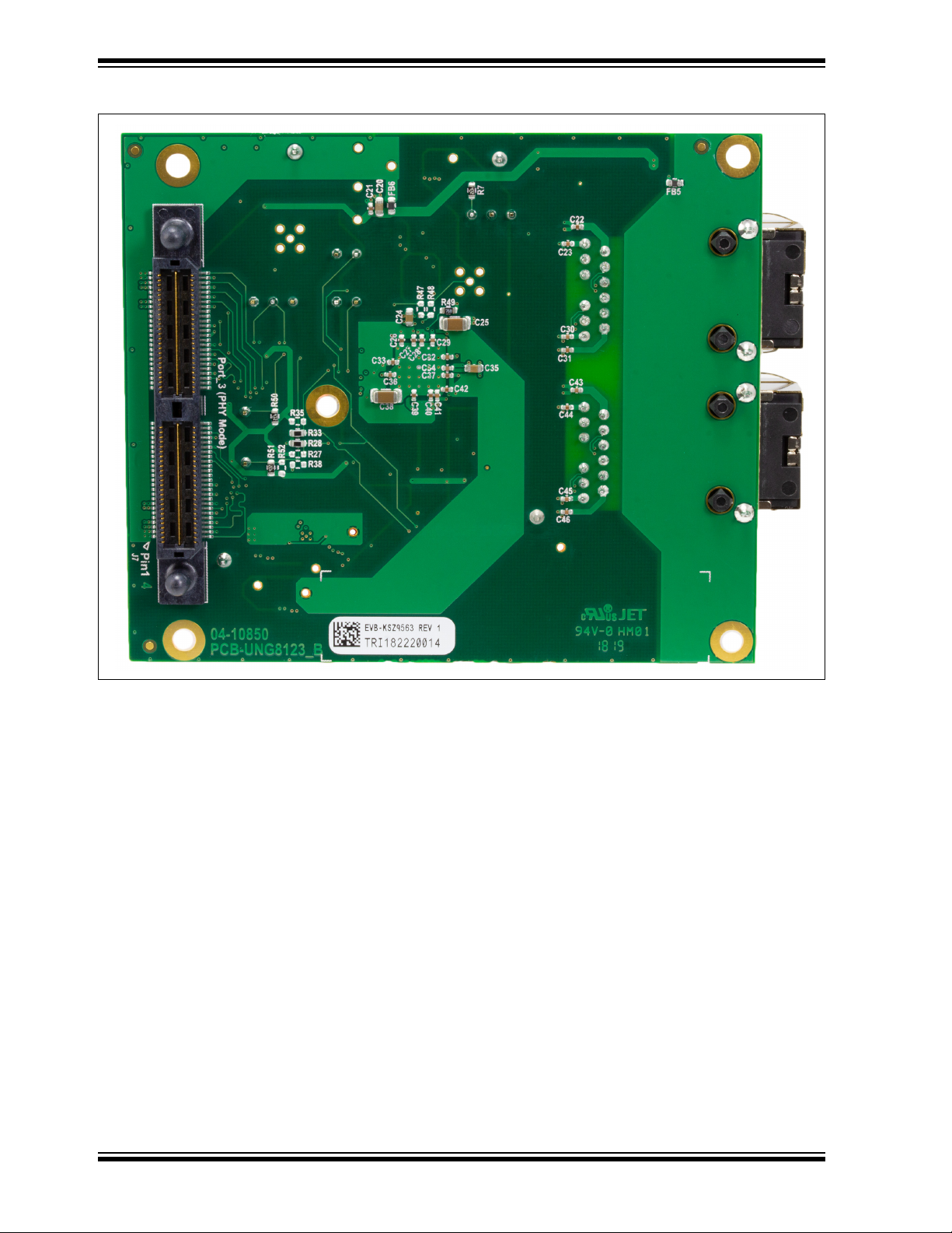
High-speed connector
to MAC processor/
controller board
Figure 2-3 displays the bottom view of the EVB-KSZ9563 with the HS connector (J7)
(highlighted in red) directly plugging into a mating Microchip MAC processor or controller board.
FIGURE 2-3: EVB-KSZ9563 BOTTOM VIEW WITH CALLOUT
2.5.1 PHY Ports – Integrated Magnetic Jacks
PHY ports 1 and 2 (J2 and J6) support 10BASE-T/100BASE-TX/1000BASE-T with
both Auto-negotiation enabled and Auto-MDI/MDI-X enabled as the power-up defaults.
2.5.2 PHY Ports – LEDs
Two Dual-LEDs (D2 and D6) provide the link status for PHY ports 1 and 2, respectively.
The LED descriptions are listed in Ta bl e 2-1.
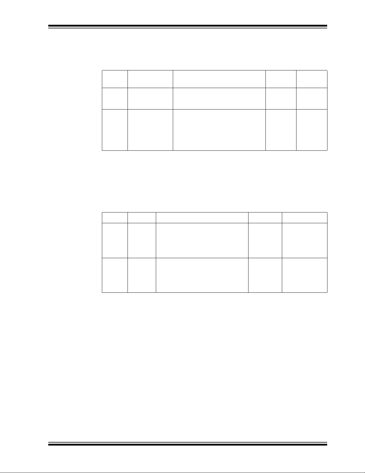
TABLE 2-1: PHY PORTS - LED DESCRIPTION
LED LED Color Description
Green Solid color: 1-Gbps Link
Blinking: Activity (RX, TX)
D2, D6
Red Solid color: 100-Mbps Link
Blinking: Activity (RX, TX)
Orange Solid color: 10-Mbps Link
Blinking: Activity (RX, TX)
Off Link off
2.5.3 Pin Strapping Configuration
As the power-up or reset defaults, the KSZ9563 device is configured via internal or
external pull-up or pull-down resistors to the following settings:
• PHY Ports 1 and 2: Au
(EEE) enabled
• MAC P
• Start Switch:
• Ma
ort 3: RGMII mode at 1000 Mbps speed
The switch forwards packets immediately after hardware reset.
nagement: SPI Slave mode
to-negotiation enabled and Energy-Efficient Ethernet
DS50002726B-page 14 2018 Microchip Technology Inc.
Page 15
Getting Started
The In-band Management Access (IBA) mode and Quiet-Wire® pin strappings can be
enabled or disabled using the 3-pin jumpers in Tab le 2-2. Set the desired jumper settings prior to board power-up, hardware reset, or both.
TABLE 2-2: PIN STRAPPING JUMPERS
Jumper Label Description
J1 IBA mode IBA provides full register read and
write access via any on
data ports.
J5 Quiet-Wire Quiet-Wire filtering is implemented
on-chip to enhance 100BASE-TX
EMC performance by reducing both
conducted and radiated emissions
from the TXP/M signal differential
pair.
e of the three
Close Pins
1-2
Disable Enable
Enable Disable
Refer to the board schematics in Appendix B. “Schematics” and the KSZ9563 Data
Sheet for further details on the pin strappings.
2.5.4 GPIO Signal Headers
Ta bl e 2-3 shows the GPIO signals that support the IEEE 1588 Precision Time Protocol
(PTP).
Close Pins
2-3
(default)
(default)
TABLE 2-3: GPIO SIGNAL HEADERS
Header Label Description Pin 1 Pin 2
J1 GPIO_2 The GPIO_2 pin is configurable to
implement IEEE1588 event trigger
outputs and timestamp capture inputs
to support real-time application
requirements.
J5 GPIO_1 The GPIO_1 pin is configurable to
implement IEEE1588 event tr
outputs and timestamp capture inputs
to support real-time application
requirements.
igger
No Connect GPIO_2
(KSZ9563
pin 40)
Ground GPIO_1
(KSZ9563
pin 39)
Refer to the board schematics in Appendix B. “Schematics” and the KSZ9563 Data
Sheet for further details and usage on the GPIO signal pins.
2.5.5 INTRP_N Output
The INTRP_N output at test point TP14 provides the interrupt output from the KSZ9563
device. By default, it is active low and drives low to turn on D4 when asserted.
Refer to the board schematics in Appendix B. “Schematics” and the KSZ9563 Data
Sheet f
or further details and usage on the INTRP_N signal.
2.5.6 PME_N Output
The PME_N output at test point TP16 provides the Power Management Event (PME)
interrupt output for Wake-on-LAN (WoL) from the KSZ9563 device. By default, it is
tive low and drives low to turn on D5 when asserted.
ac
Refer to the board schematics in Appendix B. “Schematics” and the KSZ9563 Data
Sheet f
or further details and usage on the PME_N signal.
2018 Microchip Technology Inc. DS50002726B-page 15
Page 16

EVB-KSZ9563 Evaluation Board User’s Guide
2.6 USING THE EVB-KSZ9563
The EVB-KSZ9563 directly plugs into a mating Microchip host controller or processor
board, such as the SAMA5D3-EDS Board, that delivers full power and provides full register access and configuration via IBA, SPI, or I
Together, the EVB-KSZ9563 and the SAMA5D3-EDS enable 10/100/1000-Mbps
Ether
net traffic switching across all three data ports of the KSZ9563 device, with RGMII
Port 3 connecting to the SAMA5D3 processor and PHY Port 1 and Port 2 con-
MAC
necting via copper Ethernet cable (CAT-5 UTP or better) to external Ethernet devices.
All KSZ9563 registers are accessible via IBA, SPI, or I
SAMA5D3-EDS Board, enabling full evaluation and firmware development for all
KSZ9563 MAC/Switch features and interact
Refer to the SAMA5D3-EDS Board documentation on its usage.
Figure 2-4 shows the EVB-KSZ9563 connected to the SAMA5D3-EDS Board.
FIGURE 2-4: EVB-KSZ9563 AND SAMA5D3-EDS EVALUATION AND
FIRMW
ARE DEVELOPMENT PLATFORM
ion with upper network layers.
2
C bus management.
2
C bus management from the
DS50002726B-page 16 2018 Microchip Technology Inc.
Page 17

EVB-KSZ9563
EVALUATION BOARD
USER’S GUIDE
Appendix A. EVB-KSZ9563 Evaluation Board
A.1 INTRODUCTION
This appendix shows the EVB-KSZ9563 Evaluation Board. See Figure A-1 and Figure A-2.
FIGURE A-1:
EVB-KSZ9563 EVALUATION BOARD (TOP VIEW)
2018 Microchip Technology Inc. DS50002726B-page 17
Page 18
EVB-KSZ9563 Evaluation Board User’s Guide
FIGURE A-2: EVB-KSZ9563 EVALUATION BOARD (BOTTOM VIEW)
DS50002726B-page 18 2018 Microchip Technology Inc.
Page 19

EVB-KSZ9563
EVALUATION BOARD
USER’S GUIDE
Appendix B. Schematics
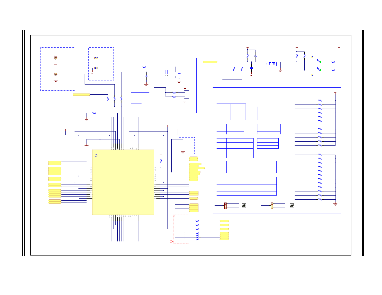
B.1 INTRODUCTION
This appendix includes the EVB-KSZ9563 Evaluation Board schematics. See Figure B-1, Figure B-2, and
Figure B-3.
2018 Microchip Technology Inc. DS50002726B-page 19
Page 20
DS50002726B-page 20 2018 Microchip Technology Inc.
AVDDH
TXRX1B_P
TXRX1B_N
TXRX1C_P
TXRX1C_N
TXRX1D_P
TXRX1D_N
TXRX2A_P
TXRX2A_N
TXRX2B_P
TXRX2B_N
TXRX2C_P
TXRX2C_N
AVDDL
TXRX2D_P
TXRX2D_N
TXRX1B_P3
TXRX1B_N3
TXRX1C_P3
TXRX1C_N3
TXRX1D_P3
TXRX1D_N3
TXRX2A_P3
TXRX2A_N3
TXRX2B_P3
TXRX2B_N3
TXRX2C_P3
TXRX2C_N3
TXRX2D_P
TXRX2D_N
TXRX2D_P3
TXRX2D_N3
TXRX1A_P
TXRX1A_N
TXRX1A_P3
TXRX1A_N3
VDDIO
DVDDL
RXD3_U1
RXD2_U1
RXD1_U1
RXD0_U1
TXD3
TXD2
TXD1
TXD0
RX_ER_U1
RX_DV_U1
RX_CLK_U1
SDI_SDA_MDIO
SDO
RESET_N
INTRP_N
PME_N
LED2_1
LED2_0
GPIO_2
GPIO_1
TX_ER
TX_EN
TX_CLK
SDI_SDA_MDIO 3
SDO 3
INTRP_N 3
PME_N 3
LED2_1 3
LED2_0 3
TX_ER 3
TX_EN 3
TX_CLK 3
TXD0 3
TXD1 3
TXD2 3
TXD3 3
RX_CLK 3
RXD0 3
RXD1 3
RXD2 3
RXD3 3
RX_ER 3
RX_DV 3
TXD0
TXD1
TXD2
TXD3
RXD0
RXD1
RXD2
RXD3
RX_DV
RX_CLK
RX_ER
SCS_N
SCL_MDC
ISET
TXRX1A_N
TXRX1A_PXIXO
LED1_0
LED1_1
SCL_MDC 3
SCS_N 3
SCL_MDC
SCS_N
LED1_1 3
LED1_0 3
LED1_1
LED1_0
6.04k
1%
R49
External Reference Clocks
Input clock
Output clock
MMCX_SYNCLKO
MMCX_XI
For AVB/1588
Place close to KSZ9563RNX
Close for MMCX
Open for test point
Open always
0.1uF DNP
C17
15pF
C14
XO
15pF
C13
XTAL-MEMS_XI
VDDIO
0.1uF
C12
Place close
to pin 46
RST_N input stability option
GPIO_2
GPIO_1
INTRP_N
PME_N
"INTRP_N"
"PME_N"
VDDIO
470R
R20
470R
R43
4.7k
R51
4.7k
R50
VDDIO
Strapping Pins
Refer to KSZ9563RNX Datasheet for detailed descriptions.
Strapping pins have internal pull-ups/pull-downs (default values);
1
1000Mbps0
Port_3 SpeedLED2_1
10/100Mbps (default)
0, 1
0, 0
1, 1
1, 0
RMII
MII (default)
Port_3 xMII ModeRXD3, RXD2
RGMII
<reserved>
MII: PHY Mode
1
RMII: Clock Mode - RMII 50MHz
Reference Clock output on RX_CLK pin
0
Port_3 MII / RMII ConfigurationLED2_0
(default)
MII: MAC Mode
RMII: Normal Mode - RMII 50MHz
Reference Clock input to TX_CLK pin
1
Start Switch disabled
Switch will not forward packets until the Start bit is set in Register 0x0_3_00.
0
Start Switch ConfigurationLED1_0
Start Switch enabled (default)
Switch will forward packets immediately after reset.
Auto-Negotiation enable with EEE enable (default)
PHY Ports 1 and 2 ConfigurationRX_ER, PME_N
0, 0
0, 1
1, 1
1, 0
<reserved>
Auto-Negotiation disable (Force 100Mbps, Full-duplex mode), and
Auto-MDIX disable (set to MDI-X mode)
Auto-Negotiation disable (Force 100Mbps, Full-duplex mode), and
Auto-MDIX disable (set to MDI mode)
VDDIO
RESET_N
0RR18
0R
R19
0R
DNP
R48
0R
DNP
R47
25REFCLK_QTS
25REFCLK_QTS3
from Samtec connector
22R
R26
22R
R32
22R
R25
RX_DV_U1
RX_CLK_U1
RX_ER_U1
22R
R21
22R
R22
22R
R23
22R
R24
RXD3_U1
RXD2_U1
RXD1_U1
RXD0_U1
RX_DV_U1
RX_CLK_U1RX_ER_U1
RXD3_U1
R
1
RXD1_U1
RXD0_U1
iNet Class
ClassName: RGMII-RX_U1
100k
R12
VDDIO
MMBD914
D3
1uF
C8
Reset
0R
DNP
R13
0R
R11
RESET_N_QTS3
RESET_N
from Samtec connector
RESET_N_QTS
RXD3_U1
RXD2_U1
RXD1_U1
RXD0_U1
RX_ER_U1
SDO_PU
4.7k
R29
4.7k
R36
4.7k
R39
4.7k
R42
4.7k DNP
R34
4.7k
R17
LED1_0
4.7k DNP
R2
LED1_1_PU
LED2_0
LED2_1
PME_N
4.7k
R7
4.7k DNP
R35
4.7k DNP
R27
4.7k DNP
R52
RXD3_U1
RXD2_U1
RXD1_U1
RXD0_U1
RX_ER_U1
SDO_PD
RX_DV_U1
LED1_0
LED1_1_PD
LED2_0
LED2_1
PME_N
750R DNP
R3
750R
R10
750R
R33
750R
R28
750R DNP
R38
750R
R44
750R DNP
R30
750R DNP
R31
750R DNP
R40
750R DNP
R41
750R
R37
750R
R16
1, x
0, 1
0, 0
Management ModeRXD1, RXD0
I2C Slave
MDC/MDIO (default)
SPI Slave
1
0
IBA ModeLED1_1
Disable
Enable (default)
1
0
Quiet-WIRESDO
Enable
Disable (default)
0RR14
0R
DNP
R15
*2-3
Quiet-WIRE
LED1_1_PD
LED1_1_PU
LED1_1
SDO_PD
SDO_PU
SDO
*2-3
IBA Mode
GPIO_2
GPIO_1
XI
SYNCLKO
SYNCLKO
GND
Test Options
Rosc
Rxtal
Rxo
P/N = ABM8G-25.000MHZ-4Y-T3
4-pin SMD, L x W (3.20mm x 2.50mm)
For Y1 = XTAL (default):
Populate Rxtal and Rxo
DNP Rosc
For Y1 = OSC:
Populate Rosc
DNP Rxtal and Rxo
4.7k
DNP
R53
VDDIO
GREEN
D4
GREEN
D5
1
2
3
J1
1
2
3
J5
1 2
JP1
1 2
JP2
2
1
MMCX Female
DNP
J4
2
1
MMCX Female
DNP
J3
TP14
TP16
TXRX1P_B
1
TXRX1M_B
2
TXRX1P_C
3
TXRX1M_C
4
TXRX1P_D
6
AVDDL
5
TXRX1M_D
7
AVDDH
8
TXRX2P_A
9
TXRX2M_A
10
AVDDL
11
TXRX2P_B
12
TXRX2M_B
13
TXRX2P_C
14
TXRX2M_C
15
AVDDL
16
TXRX2P_D17TXRX2M_D18AVD D H19DVDDL20RXD321RXD222RXD123RXD024RXC / REFCLKO / RX_CLK25VDDIO26RX_DV / CRS_DV / RX_CTL27RX_ER28TXD329TXD230TXD131TXD0
32
TXC / REFCLKI / GTX_CLK
33
DVDDL
34
TX_EN / TX_CTL
35
TX_ER
36
DVDDL
37
VDDIO
38
GPIO_1
39
GPIO_2
40
DVDDL
41
LED2_0
42
LED2_1
43
PME_N
44
INTR_N
45
RST_N
46
SDO
47
SDI / SDA / MDIO
48
SCS_N
49
KSZ9563RNX
Paddle Ground (Chip Bottom)
(QFN64)
SCL / MDC
50
P_GND
65
AVD D H
61
TXRX1P_A
62
TXRX1M_A
63
AVD D L
64
DVDDL
51
LED1_052LED1_1
53
VDDIO
54
DVDDL
55
AVD D L
56
XO
57
XI
58
GND
59
ISET
60
KSZ9563RNX
U1
1 4
2 3
SPST-NO
SW1
Place across pins 2 and 3
of IBA Mode Header
Place across pins 2 and 3
of Quiet-WIRE Header
Shunt 2.54mm 1x2
SH1
Shunt 2.54mm 1x2
SH2
4
2
13
25Mhz
Y1
FIGURE B-1: EVB-KSZ9563 SCHEMATICS – KSZ9563 DEVICE, PIN STRAPPING, CLOCK, AND RESET
EVB-KSZ9563 Evaluation Board User’s Guide
XD2_U
external pull-ups/pull-downs are used to override internal values.
Page 21

i
Net Class
ClassName: Power
TXRX1A_P
TXRX1A_N
TXRX1B_P
TXRX1B_N
TXRX1C_P
TXRX1C_N
TXRX1D_P
TXRX1D_N
TXRX1C_P 2
TXRX1C_N 2
TXRX1D_P 2
TXRX1D_N 2
RJ45_Chassis
220 OHM
FB5
RJ45_Chassis
PHY Port 1
Solid Color : 1G Link[0, 1]
Blinking : Activity (RX, TX)
Solid Color : 100M Link
Blinking : Activity (RX, TX)
[1, 0]
Solid Color : 10M Link
Blinking : Activity (RX, TX)
[0, 0]
[1, 1] Link off
Tri-color Dual-LED Mode
Pins
[LEDx_1, LEDx_0]
Description
Green
Red
Orange
[toggling, 1]
[1, toggling]
[toggling, toggling]
<off>
Dual-LED
Color
(power-up default setting)
LED1_1 2
LED1_0 2
VDDIO
VDDIO
LED2_1 2
LED2_1
LED2_0 2
LED2_0
TXRX1A_N 2
TXRX1A_P 2
TXRX1B_N 2
TXRX1B_P 2
0.1uF
C30
0.1uF
C23
0.1uF
C22
0.1uF
C31
42
1 3
GREEN
RED
GREEN, RED
D2
42
1 3
GREEN
RED
GREEN, RED
D6
TXRX2A_P
TXRX2A_N
TXRX2B_P
TXRX2B_N
TXRX2C_P
TXRX2C_N
TXRX2D_P
TXRX2D_N
0.1uF
C45
0.1uF
C44
0.1uF
C43
0.1uF
C46
TXRX2A_P 2
TXRX2A_N 2
TXRX2B_P 2
TXRX2B_N 2
TXRX2C_P 2
TXRX2D_N 2
TXRX2C_N 2
TXRX2D_P 2
LED1_1
LED1_0
MH6
MTHOLE 4-40 120DL 220PAD
MH1
Mounting Holes (for RJ45_Chassis)
RJ45_Chassis RJ45_Chassis
TXD1
i
Net Class
ClassName: QTS-PHY-RX
TXD1
i
Net Class
ClassName: QTS-PHY-TX
RX_ER
MII / RMII / RGMII Port
PHY Mode
(mount on Bottom Side of Board)
TOP VIEW - component placement side pin-outs
For the xMII pins, Micrel parts naming convention is
referenced to the PHY side regardless of whether the
switch is in MAC mode or PHY mode. That is, "TX"
named pins are inputs and "RX" named pins are outputs
for MAC mode and PHY mode.
VARIO_QTS
5V_QTS
MH2
Mounting Holes (for QTS connector)
MH3 MH4
2V5_QTS
3V3_QTS
V
ARIO_QTS
S
S
S
i
Power
ClassName: Power
RXD0
RXD2
RXD1
RXD02
RXD12
RXD22
i
Power
i
Power
"Port 1"
"Port 2"
Port 3 (PHY Mode)
i
Net Class
ClassName: Power
RJ45_Chassis
PHY Port 2
RXD3
RXD32
RX_DV
RX_DV2
RX_CLK
RX_CLK2
RX_ER2
TX_ER
TX_ER2
TX_EN
TX_CLK
TX_CLK2
TX_EN2
TXD3
TXD32
TXD2
TXD22
TXD0
TXD02
TXD12
RESET_N_QTS
INTRP_N
INTRP_N 2
RESET_N_QTS 2
PME_N
PME_N 2
SDI_SDA_MDIO
SCL_MDC
SDO
SCS_N
SCS_N 2
SDO 2
SCL_MDC 2
SDI_SDA_MDIO 2
25REFCLK_QTS
25REFCLK_QTS 2
5V_QTS
3V3_QTS
2V5_QTS
VARIO_QTS
330R
R9
330R
R4
330R
R45
330R
R46
1
3
5
7
9
11
13
15
17
19
2
4
6
8
10
12
14
16
18
20
21
23
25
27
29
31
33
35
37
39
41
43
45
47
49
51
53
55
57
59
61
63
65
67
69
71
73
75
77
79
81
83
85
87
89
91
93
95
97
99
22
24
26
28
30
32
34
36
38
40
42
44
46
48
50
52
54
56
58
60
62
64
66
68
70
72
74
76
78
80
82
84
86
88
90
92
94
96
98
100
GND
101-108
QTS-050-XX-L-D-A-GP
J7
TRD1-
10
TRCT1
12
TRD1+
11
TRD4-
9
TRCT4
7
TRD4+
8
TRD2-
5
TRCT2
6
TRD2+
4
TRD3-
2
TRCT3
1
TRD3+
3
SHIELD1
0
75 Ohms
1nF,2kV
1 TRP1+
2 TRP1-
3 TRP2+
6 TRP2-
4 TRP3+
5 TRP3-
7 TRP4+
8 TRP4-
4X
JACK RJ45 MAGJACK
J6
TRD1-
10
TRCT1
12
TRD1+
11
TRD4-
9
TRCT4
7
TRD4+
8
TRD2-
5
TRCT2
6
TRD2+
4
TRD3-
2
TRCT3
1
TRD3+
3
SHIELD1
0
75 Ohms
1nF,2kV
1 TRP1+
2 TRP1-
3 TRP2+
6 TRP2-
4 TRP3+
5 TRP3-
7 TRP4+
8 TRP4-
4X
JACK RJ45 MAGJACK
J2
PCB Layout Constraint:
Match trace lengths between the KSZ9563RNX device
and the Samtec connectors for each of the following
Class Name groupings:
* RGMII-RX_U1 + QTS-PHY-RX
* QTS-PHY-TX
2018 Microchip Technology Inc. DS50002726B-page 21
FIGURE B-2: EVB-KSZ9563 SCHEMATICS – PORTS 1 AND 2 PHYS; PORT 3 MAC – MII/RMII/RGMII CONNECTOR
2V5_QT
3V3_QT
5V_QT
Page 22

DS50002726B-page 22 2018 Microchip Technology Inc.
0.1uF
C42
0.1uF
C16
0.1uF
C37
0.1uF
C32
0.1uF
C28
AVDDL
U1 - KSZ9563RNX
Decouple Pins 5, 11, 16, 56, 64
0.1uF
C40
0.1uF
C19
0.1uF
C18
0.1uF
C33
0.1uF
C26
U1 - KSZ9563RNX
Decouple Pins 20, 34, 37, 41, 51, 55
DVDDL
FID5 FID1 FID3
FID6 FID2 FID4
i Top Layer
FID
3
i Bottom Layer
Fiducials
0.1uF
C27
MPZ1608Y101B
FB3
AVDDL
0.1uF
C9
MPZ1608Y101B
FB2
DVDDL
0.1uF
C11
1V2
1V2 @ 1.2A
4.7uF
C4
274k
R6
294K
R5
1V2
10k
R8
i
Power
i
Power
i
Power
On-board current < 0.25A
On-board current < 0.40A
TP1
"5V Ext."
2.2k
R1
5V_QTS
iPower
0.1uF
C6
i
Power
AVDDH
0.1uF
C21
i
Power
VDDIO
AVDDH
VDDIO
On-board current < 0.10A
On-board current < 0.20A
MPZ1608Y101B
DNP
FB1
MPZ1608Y101B
FB4
2V5_QTS
3V3_QTS
i
Power
i
Power
3V3_QTS
2V5_QTS
VARIO_QTS
MPZ1608Y101B
FB6
i
Power
VARIO_QTS
AVDDL
DVDDL
0.1uF
C41
0.1uF
C34
0.1uF
C29
AVDDH
U1 - KSZ9563RNX
Decouple Pins 8, 19, 61
0.1uF
C39
0.1uF
C36
0.1uF
C15
VDDIO
U1 - KSZ9563RNX
Decouple Pins 26, 38, 54
GND Test Pads
TP19 TP17 TP13 TP15
22uF
C35
22uF
C24
22uF
C7
22uF
C10
22uF
C5
22uF
C20
22uF
C25
22uF
C38
DNP
TP8
DNP
TP12
DNP
TP10
DNP
TP6
DNP
TP9
DNP
TP3
DNP
TP5
DNP
TP11
GREEN
D1
TP LOOP Black
TP18
TP LOOP Black
TP7
TP LOOP Black
TP4
TP LOOP Black
TP20
GND Test Points
SS
1
OUT
5
OUT
6
OUT
7
SW
8
SW
9
SW
10
SNS
12
FB
14
PGND
4
AGND
2
VIN
3
SS
OU
O
OU
SW
SW
SW
SNS
FB
PG
AG
VIN
EN
11
PG
13
ePAD
15
MIC33153U0
VOUT = 0.62 * [1 + (R-TOP / R-BOT)]
470pF
C1
0.1uF
C3
5V_QTS
4.7uF
C2
R-BOT = (0.62 * R-TOP) / (VOUT - 0.62)
i
Power
5V_QTS
DNP
TP2
LABEL1
FIGURE B-3: EVB-KSZ9563 SCHEMATICS – BOARD POWER I/O AND REGULATORS
T
UT
T
ND
ND
EVB-KSZ9563 Evaluation Board User’s Guide
5 FID
FID
FID6FID
Page 23

EVB-KSZ9563
EVALUATION BOARD
USER’S GUIDE
Appendix C. Bill of Materials (BOM)
C.1 INTRODUCTION
This appendix includes the EVB-KSZ9563 Evaluation Board Bill of Materials (BOM). Refer to Table C-1.
2018 Microchip Technology Inc. DS50002726B-page 23
Page 24

DS50002726B-page 24 2018 Microchip Technology Inc.
TABLE C-1: BILL OF MATERIALS
Item Qty Reference Description Populated Manufacturer Manufacturer Part Number
1 2 C13, C14 CAP CER 15 pF 50V 5% NP0 SMD 0402 YES
2 1 C1 CAP CER 470 pF 25V 5% NP0 SMD 0603 YES AVX 06033A471JAT2A
3 2 C2, C4 CAP CER 4.7 uF 10V 10% X5R SMD 0603 YES KEMET C0603C475K8PACTU
4 22
5 6 C5, C7, C10, C20, C24, C35 CAP CER 22 uF 10V 20% X5R SMD 0603 YES TDK Corporation C1608X5R1A226M080AC
6 1 C8 CAP CER 1 uF 16V 10% X5R SMD 0603 YES AVX 0603YD105KAT2A
7 9
8 2 C25, C38 CAP CER 22 uF 10V 20% X5R SMD 1206 YES Taiyo Yuden LMK316BJ226ML-T
9 3 D1, D4, D5 LED, Bright Green, 0603 YES Lite-On LTST-C191KGKT
10 2 D2, D6 DIO LED BI GREEN, RED 2V 30 mA 1210 YES Lite-On LTST-C155KGJRKT
11 1 D3 DIO RECT MMBD914LT1G 1V 10 mA 100V SMD SOT-23-3 YES ON Semiconductor MMBD914LT1G
12 4 FB2, FB3, FB4, FB6 FERRITE CHIP 100 OHM 2A 0603 YES TDK Corporation MPZ1608Y101B
13 1 FB5 FERRITE 500 mA 220R SMD 0603 YES
14 2 J1, J5 HDR 3POS 0.100-INCH SGL GOLD YES Samtec Inc. TSW-103-07-G-S
15 2 J2, J6 CON MODULAR RJ45 MAGJACK TH R/A, NO LED YES
16 2 JP1, JP2 CON HDR-2.54 MALE 1x2 GOLD 5.84 MH TH VERT YES FCI 68000-236HLF
17 1 R1 RES TKF 2.2k 1% 1/10W SMD 0603 YES
18 4 R4, R9, R45, R46 RES TKF 330R 5% 1/10W SMD 0603 YES
19 1 R5 RES TKF 294K 1% 1/10W SMD 0603 YES
20 1 R6 RES TKF 274K 1% 1/10W SMD 0603 YES
21 8 R7, R17, R29, R36, R39, R42, R50, R51 RES TKF 4.7k 5% 1/10W SMD 0603 YES Yageo RC0603JR-074K7L
22 1 R8 RES TKF 10k 5% 1/10W SMD 0603 YES
23 6 R10, R16, R28, R33, R37, R44 RES TKF 750R 1% 1/10W SMD 0603 YES Vishay CRCW0603750RFKEA
24 4 R11, R14, R18, R19 RES TKF 0R 1/10W SMD 0603 YES NIC Components NRC06Z0TRF
25 1 R12 RES TKF 100k 1% 1/10W SMD 0603 YES
26 2 R20, R43 RES TKF 470R 5% 1/10W SMD 0603 YES
C3, C6, C9, C11, C15, C16, C18, C19, C21,
C26, C27, C28, C29, C32, C33, C34, C36,
C37, C39, C40, C41, C42
C12, C22, C23, C30, C31, C43, C44, C45,
C46
CAP CER 0.1 uF 50V 10% X7R SMD 0402 YES TDK Corporation C1005X7R1H104K050BB
CAP CER 0.1 uF 50V 10% X7R SMD 0402 YES TDK Corporation C1005X7R1H104K050BB
Murata Electronics
North America
Murata Electronics
North America
Amphenol Commercial
Products
Panasonic Electronic
Components
Panasonic Electronic
Components
Panasonic Electronic
Components
Panasonic Electronic
Components
Panasonic Electronic
Components
Panasonic Electronic
Components
Panasonic Electronic
Components
GRM1555C1H150JA01D
BLM18AG221SN1D
RJMG201220030NR
ERJ-3EKF2201V
ERJ-3GEYJ331V
ERJ-3EKF2943V
ERJ-3EKF2743V
ERJ-3GEYJ103V
ERJ-3EKF1003V
ERJ-3GEYJ471V
EVB-KSZ9563 Evaluation Board User’s Guide
Page 25

2018 Microchip Technology Inc. DS50002726B-page 25
TABLE C-1: BILL OF MATERIALS (CONTINUED)
Item Qty Reference Description Populated Manufacturer Manufacturer Part Number
27 7 R21, R22, R23, R24, R25, R26, R32 RES TKF 22R 1% 1/10W SMD 0603 YES Yageo RC0603FR-0722RL
28 1 R49 RES TKF 6.04k 1% 1/10W SMD 0603 YES Yageo 9T06031A6041FBHFT
29 1 SW1
30 4 TP4, TP7, TP18, TP20 TEST POINT PC MINI 0.040-INCH HOLE DIAMETER BLACK YES Keystone Electronics 5001
31 2 TP14, TP16 CON HDR-2.54 MALE 1x1 GOLD 5.84 MH TH VERT YES Samtec TSW-101-07-G-S
32 1 U1 KSZ9563RNX 3-Port Gigabit Ethernet Switch with AVB/1588 YES Microchip Technology KSZ9563RNX
33 1 U0
34 1 J7
35 1 Y1 CRYSTAL 25 MHz 10pF SMD ABM8G YES Abracon LLC ABM8G-25.000MHZ-4Y-T3
36 0 C13, C14 CAP CER 15 pF 50V 5% NP0 SMD 0402 NO
37 0 C17 CAP CER 0.1 uF 50V 10% X7R SMD 0402 NO TDK Corporation C1005X7R1H104K050BB
38 0 FB1 FERRITE CHIP 100 OHM 2A 0603 NO TDK Corporation MPZ1608Y101B
39 0 J3, J4 CONN MMCX JACK STR 50 OHM PCB NO
40 0 R2, R27, R34, R35, R52, R53 RES TKF 4.7k 5% 1/10W SMD 0603 NO Yageo RC0603JR-074K7L
41 0 R3, R30, R31, R38, R40, R41 RES TKF 750R 1% 1/10W SMD 0603 NO Vishay CRCW0603750RFKEA
42 0 R13, R15, R47, R48 RES TKF 0R 1/10W SMD 0603 NO NIC Components NRC06Z0TRF
43 0
TP2, TP3, TP5, TP6, TP8, TP9, TP10, TP11,
TP12
Switch, Tactile, SPST, 50 mA, 16VDC, J-lead, 4.2 x 3.2 mm, PTS810,
NO
IC, 2.7V-to-5.5V input, 1.2A, Synchronous 4 MHz Buck Regulator with
adjustable output
SAMTEC - QTS-050-01-L-D-A-GP - 635 mm DOUBLE ROW HS
SOCKET ASSEMBLY
TEST POINT PC MINI 040"D RED NO Keystone Electronics 5000
YES C&K PTS810 SJM 250 SMTR LFS
YES Microchip Technology MIC33153YHJ
YES SAMTEC QTS-050-01-L-D-A-GP
Murata Electronics
North America
Cinch Connectivity
Solutions Johnson
GRM1555C1H150JA01D
135-3701-211
Page 26

EVB-KSZ9563
EVALUATION BOARD
USER’S GUIDE
Appendix D. Silk Screen
D.1 INTRODUCTION
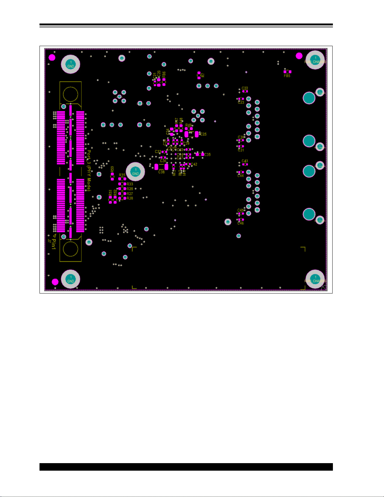
This appendix shows the EVB-KSZ9563 Evaluation Board top a nd b ott om s ilk scr e en i ma ges .
See Figure D-1 and Figure D-2.
FIGURE D-1:
EVB-KSZ9563 TOP SILK SCREEN
2018 Microchip Technology Inc. DS50002726B-page 26
Page 27
EVB-KSZ9563 Evaluation Board User’s Guide
FIGURE D-2: EVB-KSZ9563 BOTTOM SILK SCREEN
DS50002726B-page 27 2018 Microchip Technology Inc.
Page 28

Worldwide Sales and Service
AMERICAS
Corporate Office
2355 West Chandler Blvd.
Chandler, AZ 85224-6199
Tel: 480-792-7200
Fax: 480-792-7277
Technical Support:
http://www.microchip.com/
support
Web Address:
www.microchip.com
Atlanta
Duluth, GA
Tel: 678-957-9614
Fax: 678-957-1455
Austin, TX
Tel: 512-257-3370
Boston
Westborough, MA
Tel: 774-760-0087
Fax: 774-760-0088
Chicago
Itasca, IL
Tel: 630-285-0071
Fax: 630-285-0075
Dallas
Addison, TX
Tel: 972-818-7423
Fax: 972-818-2924
Detroit
Novi, MI
Tel: 248-848-4000
Houston, TX
Tel: 281-894-5983
Indianapolis
Noblesville, IN
Tel: 317-773-8323
Fax: 317-773-5453
Tel: 317-536-2380
Los Angeles
Mission Viejo, CA
Tel: 949-462-9523
Fax: 949-462-9608
Tel: 951-273-7800
Raleigh, NC
Tel: 919-844-7510
New York, NY
Tel: 631-435-6000
San Jose, CA
Tel: 408-735-9110
Tel: 408-436-4270
Canada - Toronto
Tel: 905-695-1980
Fax: 905-695-2078
ASIA/PACIFIC
Australia - Sydney
Tel: 61-2-9868-6733
China - Beijing
Tel: 86-10-8569-7000
China - Chengdu
Tel: 86-28-8665-5511
China - Chongqing
Tel: 86-23-8980-9588
China - Dongguan
Tel: 86-769-8702-9880
China - Guangzhou
Tel: 86-20-8755-8029
China - Hangzhou
Tel: 86-571-8792-8115
China - Hong Kong SAR
Tel: 852-2943-5100
China - Nanjing
Tel: 86-25-8473-2460
China - Qingdao
Tel: 86-532-8502-7355
China - Shanghai
Tel: 86-21-3326-8000
China - Shenyang
Tel: 86-24-2334-2829
China - Shenzhen
Tel: 86-755-8864-2200
China - Suzhou
Tel: 86-186-6233-1526
China - Wuhan
Tel: 86-27-5980-5300
China - Xian
Tel: 86-29-8833-7252
China - Xiamen
Tel: 86-592-2388138
China - Zhuhai
Tel: 86-756-3210040
ASIA/PACIFIC
India - Bangalore
Tel: 91-80-3090-4444
India - New Delhi
Tel: 91-11-4160-8631
India - Pune
Tel: 91-20-4121-0141
Japan - Osaka
Tel: 81-6-6152-7160
Japan - Tokyo
Tel: 81-3-6880- 3770
Korea - Daegu
Tel: 82-53-744-4301
Korea - Seoul
Tel: 82-2-554-7200
Malaysia - Kuala Lumpur
Tel: 60-3-7651-7906
Malaysia - Penang
Tel: 60-4-227-8870
Philippines - Manila
Tel: 63-2-634-9065
Singapore
Tel: 65-6334-8870
Taiwan - Hsin Chu
Tel: 886-3-577-8366
Taiwan - Kaohsiung
Tel: 886-7-213-7830
Taiwan - Taipei
Tel: 886-2-2508-8600
Thailand - Bangkok
Tel: 66-2-694-1351
Vietnam - Ho Chi Minh
Tel: 84-28-5448-2100
EUROPE
Austria - Wels
Tel: 43-7242-2244-39
Fax: 43-7242-2244-393
Denmark - Copenhagen
Tel: 45-4450-2828
Fax: 45-4485-2829
Finland - Espoo
Tel: 358-9-4520-820
France - Paris
Tel: 33-1-69-53-63-20
Fax: 33-1-69-30-90-79
Germany - Garching
Tel: 49-8931-9700
Germany - Haan
Tel: 49-2129-3766400
Germany - Heilbronn
Tel: 49-7131-67-3636
Germany - Karlsruhe
Tel: 49-721-625370
Germany - Munich
Tel: 49-89-627-144-0
Fax: 49-89-627-144-44
Germany - Rosenheim
Tel: 49-8031-354-560
Israel - Ra’anana
Tel: 972-9-744-7705
Italy - Milan
Tel: 39-0331-742611
Fax: 39-0331-466781
Italy - Padova
Tel: 39-049-7625286
Netherlands - Drunen
Tel: 31-416-690399
Fax: 31-416-690340
Norway - Trondheim
Tel: 47-7289-7561
Poland - Warsaw
Tel: 48-22-3325737
Romania - Bucharest
Tel: 40-21-407-87-50
Spain - Madrid
Tel: 34-91-708-08-90
Fax: 34-91-708-08-91
Sweden - Gothenberg
Tel: 46-31-704-60-40
Sweden - Stockholm
Tel: 46-8-5090-4654
UK - Wokingham
Tel: 44-118-921-5800
Fax: 44-118-921-5820
DS50002726B-page 28 2018 Microchip Technology Inc.
10/25/17
 Loading...