

Page 1

dsPICDEM™ MCSM
Development Board
User’s Guide
© 2009 Microchip Technology Inc. DS70610A
Page 2

Note the following details of the code protection feature on Microchip devices:
• Microchip products meet the specification contained in their particular Microchip Data Sheet.
• Microchip believes that its family of products is one of the most secure families of its kind on the market today, when used in the
intended manner and under normal conditions.
• There are dishonest and possibly illegal methods used to breach the code protection feature. All of these methods, to our
knowledge, require using the Microchip products in a manner outside the operating specifications contained in Microchip’s Data
Sheets. Most likely, the person doing so is engaged in theft of intellectual property.
• Microchip is willing to work with the customer who is concerned about the integrity of their code.
• Neither Microchip nor any other semiconductor manufacturer can guarantee the security of their code. Code protection does not
mean that we are guaranteeing the product as “unbreakable.”
Code protection is constantly evolving. We at Microchip are committed to continuously improving the code protection features of our
products. Attempts to break Microchip’s code protection feature may be a violation of the Digital Millennium Copyright Act. If such acts
allow unauthorized access to your software or other copyrighted work, you may have a right to sue for relief under that Act.
Information contained in this publication regarding device
applications and the like is provided only for your convenience
and may be superseded by updates. It is your responsibility to
ensure that your application meets with your specifications.
MICROCHIP MAKES NO REPRESENTATIONS OR
WARRANTIES OF ANY KIND WHETHER EXPRESS OR
IMPLIED, WRITTEN OR ORAL, STATUTORY OR
OTHERWISE, RELATED TO THE INFORMATION,
INCLUDING BUT NOT LIMITED TO ITS CONDITION,
QUALITY, PERFORMANCE, MERCHANTABILITY OR
FITNESS FOR PURPOSE. Microchip disclaims all liability
arising from this information and its use. Use of Microchip
devices in life support and/or safety applications is entirely at
the buyer’s risk, and the buyer agrees to defend, indemnify and
hold harmless Microchip from any and all damages, claims,
suits, or expenses resulting from such use. No licenses are
conveyed, implicitly or otherwise, under any Microchip
intellectual property rights.
Trademarks
The Microchip name and logo, the Microchip logo, dsPIC,
K
EELOQ, KEELOQ logo, MPLAB, PIC, PICmicro, PICSTART,
rfPIC and UNI/O are registered trademarks of Microchip
Technology Incorporated in the U.S.A. and other countries.
FilterLab, Hampshire, HI-TECH C, Linear Active Thermistor,
MXDEV, MXLAB, SEEVAL and The Embedded Control
Solutions Company are registered trademarks of Microchip
Technology Incorporated in the U.S.A.
Analog-for-the-Digital Age, Application Maestro, CodeGuard,
dsPICDEM, dsPICDEM.net, dsPICworks, dsSPEAK, ECAN,
ECONOMONITOR, FanSense, HI-TIDE, In-Circuit Serial
Programming, ICSP, Mindi, MiWi, MPASM, MPLAB Certified
logo, MPLIB, MPLINK, mTouch, Octopus, Omniscient Code
Generation, PICC, PICC-18, PICDEM, PICDEM.net, PICkit,
PICtail, PIC
32
logo, REAL ICE, rfLAB, Select Mode, Total
Endurance, TSHARC, UniWinDriver, WiperLock and ZENA
are trademarks of Microchip Technology Incorporated in the
U.S.A. and other countries.
SQTP is a service mark of Microchip Technology Incorporated
in the U.S.A.
All other trademarks mentioned herein are property of their
respective companies.
© 2009, Microchip Technology Incorporated, Printed in the
U.S.A., All Rights Reserved.
Printed on recycled paper.
Microchip received ISO/TS-16949:2002 certification for its worldwide
headquarters, design and wafer fabrication facilities in Chandler and
Tempe, Arizona; Gresham, Oregon and design centers in California
and India. The Company’s quality system processes and procedures
are for its PIC
devices, Serial EEPROMs, microperipherals, nonvolatile memory and
analog products. In addition, Microchip’s quality system for the design
and manufacture of development systems is ISO 9001:2000 certified.
®
MCUs and dsPIC® DSCs, KEELOQ
®
code hopping
DS70610A-page 2 © 2009 Microchip Technology Inc.
Page 3

Chapter 1. Introduction
1.1 Overview ...................................................................................................... 11
1.2 Features ....................................................................................................... 13
1.3 What’s Included ............................................................................................ 13
1.4 Reference Documents and Webinars .......................................................... 14
Chapter 2. Getting Started
2.1 Board Setup ................................................................................................. 15
2.2 Programming and Debugging Application Code .......................................... 16
Chapter 3. Hardware
3.1 Hardware Architecture .................................................................................. 17
3.2 PIM Configuration ......................................................................................... 20
3.3 Board Connectors ........................................................................................ 24
3.4 User Interface Hardware .............................................................................. 27
dsPICDEM™ MCSM DEVELOPMENT
BOARD USER’S GUIDE
Table of Contents
Chapter 4. Troubleshooting
4.1 Common Problems ....................................................................................... 29
Appendix A. Board Layout and Schematics
Appendix B. Electrical Specifications
© 2009 Microchip Technology Inc. DS70610A-page 3
Page 4

dsPICDEM™ MCSM Development Board User’s Guide
NOTES:
DS70610A-page 4 © 2009 Microchip Technology Inc.
Page 5
dsPICDEM™ MCSM DEVELOPMENT
BOARD USER’S GUIDE
Preface
NOTICE TO CUSTOMERS
All documentation becomes dated, and this manual is no exception. Microchip tools and
documentation are constantly evolving to meet customer needs, so some actual dialogs and/
or tool descriptions may differ from those in this document. Please refer to our web site
(www.microchip.com) to obtain the latest documentation available.
Documents are identified with a “DS” number. This number is located on the bottom of each
page, in front of the page number. The numbering convention for the DS number is
“DSXXXXXA”, where “XXXXX” is the document number and “A” is the revision level of the
document.
For the most up-to-date information on development tools, see the MPLAB
Select the Help menu, and then Topics to open a list of available on-line help files.
INTRODUCTION
®
IDE on-line help.
This preface contains general information that will be useful to know before using the
dsPICDEM™ Motor Control Stepper Motor (MCSM) Development Board. Topics
discussed in this preface include:
• Document Layout
• Conventions Used in this Guide
• Warranty Registration
• Recommended Reading
• The Microchip Web Site
• Development Systems Customer Change Notification Service
• Customer Support
• Document Revision History
DOCUMENT LAYOUT
This user’s guide describes how to use the dsPICDEM MCSM Development Board.
The document is organized as follows:
• Chapter 1. “Introduction” – This chapter introduces the dsPICDEM MCSM
Development Board and provides a brief overview of its features.
• Chapter 2. “Getting Started” – This chapter provides information on getting
started with the dsPICDEM MCSM Development Board.
• Chapter 3. “Hardware” – This chapter describes the hardware on the dsPICDEM
MCSM Development Board.
• Chapter 4. “Troubleshooting” – This chapter provides information for
troubleshooting problems encountered while using the dsPICDEM MCSM
Development Board.
© 2009 Microchip Technology Inc. DS70610A-page 5
Page 6

dsPICDEM™ MCSM Development Board User’s Guide
• Appendix A. “Board Layout and Schematics” – This appendix provides
diagrams of the hardware layout, as well as schematic diagrams for the
dsPICDEM MCSM Development Board.
• Appendix B. “Electrical Specifications” – This appendix provides pertinent
electrical specifications for the dsPICDEM MCSM Development Board.
DS70610A-page 6 © 2009 Microchip Technology Inc.
Page 7
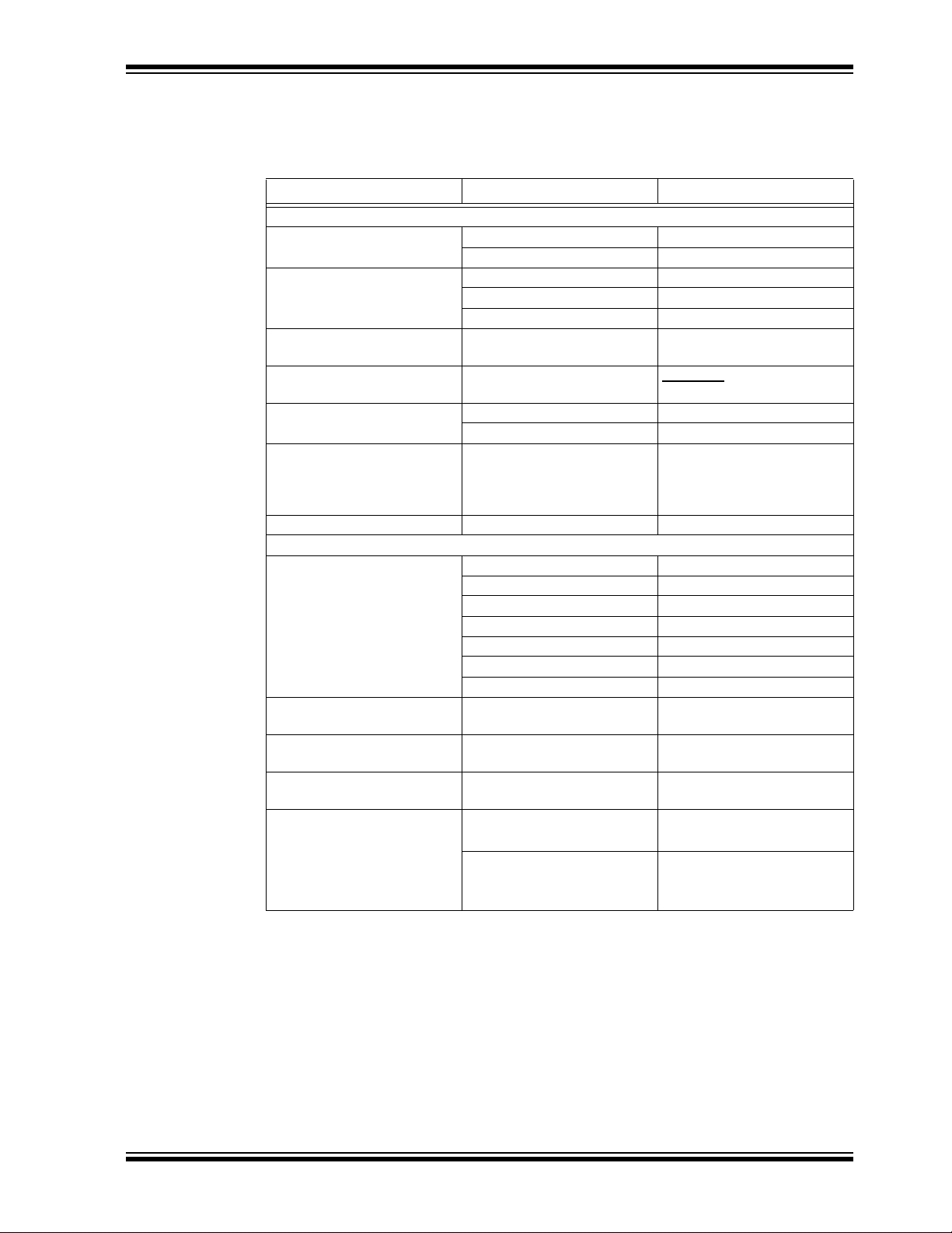
CONVENTIONS USED IN THIS GUIDE
This manual uses the following documentation conventions:
DOCUMENTATION CONVENTIONS
Description Represents Examples
Arial font:
Italic characters Referenced books MPLAB® IDE User’s Guide
Initial caps A window the Output window
Quotes A field name in a window or
Underlined, italic text with
right angle bracket
Bold characters A dialog button Click OK
N‘Rnnnn A number in verilog format,
Text in angle brackets < > A key on the keyboard Press <Enter>, <F1>
Courier New font:
Plain Courier New Sample source code #define START
Italic Courier New A variable argument file.o, where file can be
Square brackets [ ] Optional arguments mcc18 [options] file
Curly braces and pipe
character: { | }
Ellipses... Replaces repeated text
Preface
Emphasized text ...is the only compiler...
A dialog the Settings dialog
A menu selection select Enable Programmer
“Save project before build”
dialog
A menu path File>Save
A tab Click the Power tab
4‘b0010, 2‘hF1
where N is the total number of
digits, R is the radix and n is a
digit.
Filenames autoexec.bat
File paths c:\mcc18\h
Keywords _asm, _endasm, static
Command-line options -Opa+, -Opa-
Bit values 0, 1
Constants 0xFF, ‘A’
any valid filename
[options]
Choice of mutually exclusive
arguments; an OR selection
Represents code supplied by
user
errorlevel {0|1}
var_name [,
var_name...]
void main (void)
{ ...
}
© 2009 Microchip Technology Inc. DS70610A-page 7
Page 8

dsPICDEM™ MCSM Development Board User’s Guide
WARRANTY REGISTRATION
Please complete the enclosed Warranty Registration Card and mail it promptly.
Sending in the Warranty Registration Card entitles users to receive new product
updates. Interim software releases are available at the Microchip web site.
RECOMMENDED READING
This user’s guide describes how to use the dsPICDEM MCSM Development Board. The
device-specific data sheets contain current information on programming the specific
microcontroller or digital signal controller devices. Other useful documents are listed
below. The following Microchip documents are available and recommended as
supplemental reference resources:
MPLAB
This user’s guide is a comprehensive guide that describes installation and features of
Microchip’s MPLAB Integrated Development Environment (IDE), as well as the editor
and simulator functions in the MPLAB IDE environment.
Readme Files
For the latest information on using other tools, read the tool-specific Readme files in the
Readme subdirectory of the MPLAB IDE installation directory. The Readme files contain
updated information and known issues that may not be included in this user’s guide.
MPASM™ Assembler, MPLINK™ Object Linker, MPLIB™ Object Librarian User’s
Guide (DS33014)
This user’s guide describes how to use the Microchip MPASM Assembler, the MPLINK
Object Linker and the MPLIB Object Librarian.
dsPIC33FJ12MC202 PIM Information Sheet (DS70314)
This document provides device-specific information for the dsPIC33FJ12MC202 PIM
device. The dsPIC33FJ12MC202 is a high-performance 16-bit digital signal controller
within a small 28-pin 6x6 mm QFN package.
dsPIC33FJ32MC204 PIM Information Sheet (DS70316)
This document provides device specific information for the dsPIC33FJ32MC204 PIM
device. The dsPIC33FJ32MC204 is a high-performance 16-bit digital signal controller
within a small 44-pin QFN package.
dsPIC33FJ128MC804 PIM Information Sheet (DS70326)
This document provides device specific information for the dsPIC33FJ128MC804 PIM
device. The dsPIC33FJ128MC804 is a high-performance 16-bit digital signal controller
within a small 44-pin QFN package.
dsPIC33FJ256MC710 PIM Information Sheet (DS70564)
This document provides device specific information for the dsPIC33FJ256MC710 PIM
device. The dsPIC33FJ256MC710 is a high-performance 16-bit digital signal controller
within a small 100-pin TQFP package.
dsPIC33FJ12MC201/202 Data Sheet (DS70265)
This data sheet contains device specific information for the dsPIC33FJ12MC201/202
Digital Signal Controller (DSC) devices. The dsPIC33F devices contain extensive
Digital Signal Processor (DSP) functionality with a high performance 16-bit
microcontroller (MCU) architecture.
dsPIC33FJ32MC202/204 and dsPIC33FJ16MC304 Data Sheet (DS70283)
This data sheet provides device specific information for the dsPIC33FJ32MC202/204
and dsPIC33FJ16MC304 motor control family of devices.
®
IDE Simulator, Editor User’s Guide (DS51025)
DS70610A-page 8 © 2009 Microchip Technology Inc.
Page 9

dsPIC33FJ32MC302/304, dsPIC33FJ64MCX02/X04, and dsPIC33FJ128MCX02/
X04 Data Sheet (DS70291)
This data sheet contains device specific information for the dsPIC33FJ32MC302/304,
dsPIC33FJ64MCX02/ X04 and dsPIC33FJ128MCX02/X04 motor control family of
devices.
dsPIC33FJXXXMCX06/X08/X10 Data Sheet (DS70287)
This data sheet contains device specific information for the dsPIC33FJXXXMCX06/
X08/X10 motor control family of devices.
To download these documents, visit Microchip web site at www.microchip.com.
THE MICROCHIP WEB SITE
Microchip provides online support via our web site at www.microchip.com. This web
site is used as a means to make files and information easily available to customers.
The web site contains the following information:
• Product Support – Data sheets and errata, application notes and sample
programs, design resources, user’s guides and hardware support documents,
latest software releases and archived software
• General Technical Support – Frequently Asked Questions (FAQs), technical
support requests, online discussion groups, Microchip consultant program
member listing
• Business of Microchip – Product selector and ordering guides, latest Microchip
press releases, listing of seminars and events, listings of Microchip sales offices,
distributors and factory representatives
Preface
DEVELOPMENT SYSTEMS CUSTOMER CHANGE NOTIFICATION SERVICE
Microchip’s customer notification service helps keep customers current on Microchip
products. Subscribers will receive e-mail notification whenever there are changes,
updates, revisions or errata related to a specified product family or development tool of
interest.
To register, access the Microchip web site at www.microchip.com, click on Customer
Change Notification and follow the registration instructions.
The Development Systems product group categories are:
• Compilers – The latest information on Microchip C compilers and other language
tools. These include the MPLAB
and MPLAB ASM30 assemblers; MPLINK™ and MPLAB LINK30 object linkers;
and MPLIB™ and MPLAB LIB30 object librarians.
• Emulators – The latest information on Microchip in-circuit emulators.This
includes the MPLAB ICE 2000, MPLAB ICE 4000, and MPLAB REAL ICE™.
• In-Circuit Debuggers – The latest information on the Microchip in-circuit
debugger, MPLAB ICD 2.
• MPLAB
Integrated Development Environment for development systems tools. This list is
focused on the MPLAB IDE, MPLAB SIM simulator, MPLAB IDE Project Manager
and general editing and debugging features.
• Programmers – The latest information on Microchip programmers. These include
the MPLAB PM3 and PRO MATE
Plus and PICkit™ 1development programmers.
®
IDE – The latest information on Microchip MPLAB IDE, the Windows®
®
C18 and MPLAB C30 C compilers; MPASM™
®
II device programmers and the PICSTART®
© 2009 Microchip Technology Inc. DS70610A-page 9
Page 10

dsPICDEM™ MCSM Development Board User’s Guide
CUSTOMER SUPPORT
Users of Microchip products can receive assistance through several channels:
• Distributor or Representative
• Local Sales Office
• Field Application Engineer (FAE)
• Technical Support
• Development Systems Information Line
Customers should contact their distributor, representative or field application engineer
(FAE) for support. Local sales offices are also available to help customers. A listing of
sales offices and locations is included in the back of this document.
Technical support is available through the web site at: http://support.microchip.com
DOCUMENT REVISION HISTORY
Revision A (September 2009)
This is the initial released revision of this document.
DS70610A-page 10 © 2009 Microchip Technology Inc.
Page 11

dsPICDEM™ MCSM
DEVELOPMENT BOARD
USER’S GUIDE
Chapter 1. Introduction
The dsPICDEM MCSM Development Board is targeted to control both unipolar and
bipolar stepper motors with no hardware configuration changes. This flexible and
cost-effective board can be configured in different ways for use with Microchip’s
specialized dsPIC33F Motor Control Digital Signal Controllers (DSCs).
The dsPICDEM MCSM Development Board offers a mounting option to connect either
a 28-pin SOIC device or a generic 100-pin Plug-In Module (PIM). The board also has
two full-bridge inverters. The hardware is designed in such a way that no hardware
changes are necessary for 8-, 6- or 4-wire stepper motors in either bipolar or unipolar
configurations. Topics covered include:
•Overview
•Features
• What’s Included
• Reference Documents and Webinars
1.1 OVERVIEW
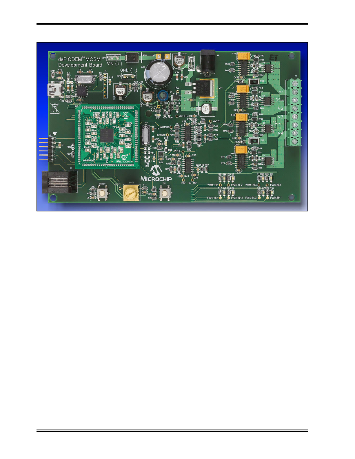
Figure 1-1 shows a photograph of the dsPICDEM MCSM Development Board. A
dsPIC33F device uses the MOSFET driver to drive the two full-bridge inverters that
power the motor windings. The board includes various circuitries to perform the
following functions:
• Drive two motor windings with the two on-board full-bridge inverters
• Measure feedback and other analog signals (i.e., current, DC voltage,
• Communicate with a host computer or an external device via USB
The dsPICDEM MCSM Development Board supports terminal voltages up to 80V and
currents up to 3A. Refer to Appendix B. “Electrical Specifications” for more
information.
Potentiometer and Fault signals)
© 2009 Microchip Technology Inc. DS70610A-page 11
Page 12
dsPICDEM™ MCSM Development Board User’s Guide
FIGURE 1-1: dsPICDEM MCSM DEVELOPMENT BOARD
DS70610A-page 12 © 2009 Microchip Technology Inc.
Page 13

1.2 FEATURES
The key features of this board include the following:
• Devices supported:
• Motor control device (U2) socket
• Motor control interfaces:
• Input/output control switches:
• Communication Ports:
• Built-in power supplies
• Power supply connectors:
• Programming Connectors:
Introduction
- 28-pin to 100-pin dsPIC33FJ12MC202 PIM (MA330014) with a dsPIC33F
- 44-pin to 100-pin dsPIC33FJ32MC204 PIM (MA330017) and
dsPIC33FJ128MC804 PIM (MA330018) with a dsPIC33F motor control
device (U2) socket
- 100-pin to 100-pin dsPIC33FJ256MC710 PIM (MA330013) with a dsPIC33F
- The dsPIC33FJ12MC202 Motor Control device in SOIC package (U3)
footprint
- Two full-bridge inverters
- Two phase current sense resistors
- DC bus voltage sense resistor
- Overcurrent protection
- One push button (S1)
- Reset push button (RESET)
-10 kΩ potentiometer (POT)
- LED indicators for PWM outputs arranged in a full-bridge format
- LED indicator for overcurrent
- UART communication via USB (J4)
- 15V power supply, maximum power available 11 W
- 3.3V power supply, maximum power available 2 W
- 24V power input connector (J6) for the controller and power stage
- Auxiliary Power Tab Fast-On connectors (BP1 and BP2) for the power stage
- ICSP™ connector for programming a dsPIC DSC device (J2)
- RJ11 connector for programming a dsPIC DSC device (J1)
- ICSP connector for programming the PIC18LF2450 USB-to-UART Bridge (J3)
1.3 WHAT’S INCLUDED
Note: The MCSM Development Board is available in two configurations:
• dsPICDEM MCSM Development Board
• dsPICDEM MCSM Development Board Kit
© 2009 Microchip Technology Inc. DS70610A-page 13
Page 14

dsPICDEM™ MCSM Development Board User’s Guide
The dsPICDEM MCSM Development Board with the part number DM330022 contains
the following:
• dsPICDEM MCSM Development Board
• dsPIC33FJ32MC204 Plug-In-Module
• USB-to-mini-USB cable
• Screwdriver
• dsPICDEM MCSM Development Board CD ROM, which includes:
- This user’s guide
- Data sheets for dsPIC families
- Example programs for use with the dsPIC DSC devices
The dsPICDEM MCSM Development Board Kit with part number DV330021 contains
the following:
• dsPICDEM MCSM Development Board
• dsPIC33FJ32MC204 Plug-In-Module (PIM)
• USB-to-mini-USB cable
• Screwdriver
• dsPICDEM MCSM Development Board CD ROM, which includes:
- This user’s guide
- Data sheets for dsPIC DSC families
- Example programs for use with the dsPIC DSC devices
• 24V Power Supply
• Leadshine Stepping Motor (P/N 42HS03)
• use the following link:
http://www.leadshine.com
If you are missing any part of the kit, please contact your nearest Microchip sales office,
which is listed on the last page of this manual.
1.4 REFERENCE DOCUMENTS AND WEBINARS
In addition to the documents listed in the “Recommended Reading” section, the
following are also available from Microchip to support the use of the dsPICDEM MCSM
Development Board.
•AN907 “Stepping Motors Fundamentals”
•AN906 “Stepper Motor Control Using the PIC16F684”
•AN822 “Motor Microstepping with PIC18C452”
• Stepper motor webinars are available at:
http://techtrain.microchip.com/webseminars/Archived.aspx
- Stepper Motors Part 1: Types of Stepper Motors
- Stepper Motors Part 2: Stepper Motor Control
You can obtain these reference documents from your nearest Microchip sales office
(listed in the last page of this document) or by downloading them from the Microchip
web site.
DS70610A-page 14 © 2009 Microchip Technology Inc.
Page 15

This chapter describes how to set up the dsPICDEM MCSM Development Board
hardware and software; and how to run the included demonstration software. Refer to
Chapter 3. “Hardware” for detailed information on the board and its components.
Topics in this chapter include:
• Board Setup
• Programming and Debugging Application Code
2.1 BOARD SETUP
The dsPICDEM MCSM Development Board is intended to drive bipolar or unipolar stepper motors. Before connecting the motor, make sure that the power rating of the motor
is equal to or less than the power rating of the board, as shown in Appendix
B. “Electrical Specifications”. Also, make sure the configuration resistors are correct
for the firmware and the specific dsPIC DSC device mounted on the socket. Failure to
comply with this warning could lead to malfunction of the board and the motor, and
could result in physical harm.
dsPICDEM™ MCSM
DEVELOPMENT BOARD
USER’S GUIDE
Chapter 2. Getting Started
WARNING
Before beginning the start-up procedure, complete a visual check of the board and the
motor for connectivity and mechanical damage. If damage is found, DO NOT power-up
the board. Otherwise, you may further damage the equipment. Contact Microchip’s
local office or distributor immediately.
The following procedure describes how to set up the dsPICDEM MCSM Development
Board to run with the demonstration software. The stepper motor used for the
demonstration is the Leadshine Stepping Motor (P/N 42HS03).
1. Place the dsPICDEM MCSM Development Board on a sturdy insulated platform.
2. Make sure that the dsPIC33FJ32MC204 device or an appropriate PIM is
mounted in the respective socket.
3. Connect the stepper motor (42HS03) to J8. Connect the motor phases in a bipolar series connection as described in Table 2-1.
TABLE 2-1: MOTOR CONFIGURATION TABLE
J8 Pin Number
J8 Pin Name
1 NC Green+Yellow — Yellow —
2 M1 Black Black+Yellow Black Black
3 DC+ — — Orange Green+Yellow
4 M2 Orange Green+Orange Green Orange
5 M3 Red Red+White Red Red
6 DC+ — — White Blue+White
7 M4 Brown Blue+Brown Blue Brown
8 NC Blue+White — Brown —
Bipolar
Series
Bipolar Parallel Bipolar Half-winding Unipolar
© 2009 Microchip Technology Inc. DS70610A-page 15
Page 16

dsPICDEM™ MCSM Development Board User’s Guide
4. Connect the 24V power supply to J6.
5. Press S1 to run the motor.
6. Vary the motor’s speed with the potentiometer.
7. Press S1 to switch to full-step wave mode, full-step, half-step and various
microstepping modes. Pushing S1 after the 256
the motor. Press S1 again to repeat the cycle.
Operating the dsPICDEM MCSM Development Board using the on-board POT and
switch button cannot offer the flexibility required in most applications and it is only
intended as a quick start demonstration. To have more control over the motor using a
real-time communication tool, please refer to the next section.
2.2 PROGRAMMING AND DEBUGGING APPLICATION CODE
The following procedure describes how to program the dsPICDEM MCSM
Development Board in Debug mode:
1. Place the dsPICDEM MCSM Development Board on a sturdy insulated platform.
2. Make sure that the dsPIC33FJ32MC204 device or an appropriate PIM is
mounted in the respective socket.
3. Connect the stepper motor (42HS03) to J8. Connect motor phases in a bipolar
series connection as described in Table 2-1.
4. Connect the 24V power supply to J6.
5. Connect PICkit™ 3 In-Circuit Debugger/Programmer, MPLAB
REAL ICE™ In-Circuit Emulator to the computer and to the board at J1 or J2.
6. Connect the USB cable to J4 and to the computer.
7. Download the code for the dsPIC33FJ32MC204 from the Microchip web site .
8. Build the project and download the program into the processor.
9. Click the Run icon when in Debug mode.
th
microstep step setting stops
®
ICD 3 or MPLAB
Note: For more information on running stepper motors, refer to
Section 1.4 “Reference Documents and Webinars”.
DS70610A-page 16 © 2009 Microchip Technology Inc.
Page 17

Chapter 3. Hardware
dsPIC33FJXXXMCXXX
PIM
Drivers
IMOTOR1
FAULT
IMOTOR2
Safe Current
Level
Amplifier
Amplifier
Comparator
PWM1H1
DC_BUS
24 VDC
BP1
BP2
J5
J7
J6
15V3.3V
Regulator
Regulator
PWM1L1
PWM1H2
PWM1L2
PWM1H3
PWM1L3
PWM2H1
PWM2L1
M1
M2
M3
M4
J8
M
UART
to
USB
USB
J4
ICD2
J1/J2
3.3V
POT
S1
DC_BUS
M1
M2
M3
M4
This chapter describes the hardware used in the dsPICDEM MCSM Development
Board. Topics covered include:
• Hardware Architecture
• PIM Configuration
• Board Connectors
• User Interface Hardware
3.1 HARDWARE ARCHITECTURE
The dsPIC DSC devices feature an 8-channel, high-speed PWM with Complementary
mode output, a programmable ADC trigger on the PWM reload cycle, digital dead time
control, internal shoot-through protection and hardware fault shutdown.
These features make the dsPIC DSC an ideal solution for high-performance stepper
motor control applications where full control of the full-bridge inverter is required.
Figure 3-1 provides a simplified block diagram of the development board hardware.
dsPICDEM™ MCSM
DEVELOPMENT BOARD
USER’S GUIDE
FIGURE 3-1: dsPICDEM MCSM DEVELOPMENT BOARD BLOCK DIAGRAM
© 2009 Microchip Technology Inc. DS70610A-page 17
Page 18

dsPICDEM™ MCSM Development Board User’s Guide
T1 T2 T1 T2
PWM1H1PWM1L1
PWM1H2PWM1L2
PWM1H1
PWM1L1
PWM1H2
PWM1L2
T1
PWM1H1PWM1L1
PWM1H2PWM1L2
3.1.1 Power Stage
The dsPICDEM MCSM Development Board features two full-bridge inverters to accommodate a bipolar stepper motor. MOSFET gate signals are powered from a 15V permanent supply while the full-bridge inverters can be powered from a supply up to 80V.
3.1.1.1 MOSFET DRIVER
Although the dsPIC DSC devices can operate in Complementary PWM mode,
Independent PWM mode is still possible. In this case, internal dead time control and
shoot-through protection circuits are disabled. In order to protect the power stage from
high shoot-through currents in Independent PWM mode, the chosen MOSFET driver
also has a built-in shoot-through protection and a small fixed dead time. In Independent
PWM mode, the development board is suitable for controlling two brushed DC motors
with full direction control, or up to four DC motors with a single turning direction.
3.1.1.2 SWITCHING TOPOLOGY
Driving a stepper motor in a full-bridge topology requires switching the opposite
diagonal MOSFETs on and off at the same time in order to reverse the drive current
and to accommodate all possible decay modes. Since all PWMxHx pins are on at the
same time (for example, PWM1H1 and PWM1H2), it is not possible to drive all of the
high-side MOSFETs with the PWMxHx signals. Figure 3-2 shows the PWM and
MOSFET assignment.
Driving the high PWM pins active will run the current through a motor winding in one
direction, while driving the low PWM pins active will run the current through the winding
in the opposite direction. By using this topology in addition to the dsPIC PWM Override
feature, all decay modes for the winding current can be achieved.
Refer to Appendix A. “Board Layout and Schematics” for the complete schematic
and PWM pin assignments.
FIGURE 3-2: MOSFET PWM ASSIGNMENT
DS70610A-page 18 © 2009 Microchip Technology Inc.
Page 19

Hardware
Gain R
SHUNT
R
27
R28R29+
---------------------- -
⋅=
Note: The default gain value is 0.75 V/A, allowing a resolution of 67 µA/bit with
a 10-bit ADC.
DC_REF
1
28
----- -
DC_BUS=
3.1.2 Current Sensing
Two shunt resistors are available for current sensing, one for each of the two motor
windings. In order to read both positive and negative currents, the amplifier circuit is
designed with an offset of V
current range of ±2.2A.
To calculate the amplifier gain, use the formula provided in Equation 3-1:
EQUATION 3-1: AMPLIFIER GAIN CALCULATION FORMULA
The formula shown in Equation 3-1 is a simplified version of the complete formula and
is only valid when R
28
are needed, use the above formula to calculate R
and then replace both R
changes for R
and R45.
39
The DC voltage supplied to the power stage is measured with a simple resistor divider.
To calculate the DC_REF signal used for this purpose use the formula provided in
Equation 3-2:
REF = AVDD/2. The amplifier gain allows for a maximum
= R29 = R33 = R34 and R27 = R35. If changes to the amplifier gain
corresponding to the desired gain,
and R35 with the calculated resistor value. Make the same
27
27
EQUATION 3-2: DC_REF SIGNAL CALCULATION FORMULA
This measurement is needed in the PI loop calculation and for algorithms such as
automatic motor induction and resistance identification.
3.1.3 Fault Protection
The dsPICDEM MCSM Development Board features an overcurrent fault detection,
which triggers a PWM shutdown. Each phase current is amplified and then compared
with a fixed “safe” current value. A value of 1.7A is set for the dsPICDEM MCSM
Development Board; however, the user can change this limit by changing the resistor
divider made by R48 and R51. When either of the two phase currents is above the
“safe” current level, a Fault signal is triggered and the dsPIC DSC hardware module
automatically switches off all PWM outputs.
The Fault LED (D15) is active only when an overcurrent is present in the motor
windings. It will go inactive immediately after the internal dsPIC Fault circuit shuts down
the PWM pins. In this case, the LED will not be visible as the on-time is very short. The
Fault LED will only be visible if the Fault is persistent, that is when the software fault
shutdown is disabled.
For details about the PWM module Fault feature, please refer to Section 14. “Motor
Control PWM” (DS70187) in the “dsPIC33F Family Reference Manual”.
WARNING
If the Fault LED is permanently active, power off the board immediately to avoid
damage to the power Mosfets.
© 2009 Microchip Technology Inc. DS70610A-page 19
Page 20

dsPICDEM™ MCSM Development Board User’s Guide
3.2 PIM CONFIGURATION
This section summarizes the resistor configurations required to connect the PIM pins
to the dsPIC DSC pins. The following PIMs can be configured on the dsPICDEM
MCSM Development Board:
• dsPIC33FJ256MC710 PIM (MA330013)
• dsPIC33FJ12MC202 PIM (MA330014)
• dsPIC33FJ32MC204 PIM (MA330017)
• dsPIC33FJ128MC804 PIM (MA330018)
Table 3-1, Table 3-2 and Table 3-3 describe the PIM configuration details. The
dsPIC33FJ32MC204 and dsPIC33FJ128MC804 PIMs are pin-compatible and share
the same table.
DS70610A-page 20 © 2009 Microchip Technology Inc.
Page 21

Hardware
TABLE 3-1: dsPIC33FJ256MC710 CONFIGURATION DETAILS
PIM Pin
Number
3PWM1H3 3PWM3H/RE5 —
4 PWM2L1 4 PWM4L/RE6 —
5PWM2H1 5PWM4H/RE7 —
13 MCLR 13 MCLR
18 PWM2H1 — AN20/FLTA/INT1/RE8 Not used, set pin as input
19 FAULT_1 19 AN21/FLTB/INT2/RE9 Solder R86, remove R87
20 POT 20 AN5/QEB/CN7/RB5 Not used, set pin as input
22 POT 22 AN3/INDX/CN5/RB3 —
23 DC_REF 23 AN2/SS1/CN4/RB2 —
24 IMOTOR2 24 PGEC3/AN1/CN3/RB1 —
25 IMOTOR1 25 PGED3/AN0/CN2/RB0 —
26 PGC 26 PGEC1/AN6/OCFA/RB6 —
27 PGD 27 PGED1/AN7/RB7 —
35 DC_REF 35 AN11/RB11 Not used, set pin as input
41 POT 41 AN12/RB12 Not used, set pin as input
49 USB_RX 49 U2RX/CN17/RF4 —
50 USB_TX 50 U2TX/CN18/RF5 —
51 USB_TX 51 U1TX/RF3 —
52 USB_RX 52 U1RX/RF2 —
54 USB_VBUS — SDI1/RF7 Not used, set pin as input
55 USB_3.3V — SCK1/INT0/RF6 Not used, set pin as input
56 USB_D- — SDA1/RG3 Not used, set pin as input
57 USB_D+ — SCL1/RG2 Not used, set pin as input
63 OSCI 63 OSC1/CLKIN/RC12 —
64 OSCO 64 OSC2/CLKO/RC15 —
68 FAULT_1 68 IC1/RD8 Not used, set pin as input
70 BTN_1 70 IC3/RD10 —
76 USB_TX 76 OC2/RD1 Not used, set pin as input
77 PWM2H1 77 OC3/RD2 Not used, set pin as input
78 PWM2L1 78 OC4/RD3 Not used, set pin as input
83 USB_TX — OC7/CN15/RD6 Not used, set pin as input
84 USB_RX — OC8/UPDN//CN16/RD7 Not used, set pin as input
93 PWM1L1 93 PWM1L/RE0 —
94 PWM1H1 94 PWM1H/RE1 —
98 PWM1L2 98 PWM2L/RE2 —
99 PWM1H2 99 PWM2H/RE3 —
100 PWM1L3 100 PWM3L/RE4 —
Note 1: When using a dsPIC33FJ256MC710 it is necessary to set PIM pin 19 as FAULT_1. PIM Pin 19 can be
configured for FAULT_1 or PWM2L1 signals by soldering the appropriate resistor as follows:
Labels on the
MCSM Board
Pin Number Pin Name
dsPIC33FJ256MC710
(1)
Comment/Board
Resistor Configuration
—
• For FAULT_1 : Remove R87 and Solder R86
• For PWM2L1 : Remove R86 and Solder R87 (Default)
© 2009 Microchip Technology Inc. DS70610A-page 21
Page 22

dsPICDEM™ MCSM Development Board User’s Guide
TABLE 3-2: dsPIC33FJ12MC202 CONFIGURATION DETAILS
PIM Pin
Number
3 PWM1H3 18 TDI/PWM1H3/RP10/CN16/RB10 Solder R12
4PWM2L1 — — —
5PWM2H1 — — —
13 MCLR 26 MCLR
18 PWM2H1 14 TCK/PWM2H1/SCL1/RP8/CN22/RB8 Solder R11
19 PWML1 15 TDO/PWM2L1/SDA1/RP9/CN21/RB9 Solder R14, solder R13
20 POT 2 PGC1/EMUC1/AN3/RP1/CN5/RB1 Solder R31, remove R21
22 POT — — Remove R9
23 DC_REF — — —
24 IMOTOR2 28 PGC2/EMUC2/AN1/VREF-/CN3/RA1 Solder R25, remove R26
25 IMOTOR1 27 PGD2/EMUD2/AN0/VREF+/CN2/RA0 Solder R24, remove R27
26 PGC 9 PGC3/EMUC3/SOSCO/T1CK/CN0/RA4 —
27 PGD 8 PGD3/EMUD3/SOSCI/RP4/CN1/RB4 —
35 DC_REF 1 PGD1/EMUD1/AN2/RP0/CN4/RB0 Solder R20, remove R28
41 POT — — —
49 USB_RX — — —
50 USB_TX — — —
51 USB_TX — — —
52 USB_RX — — —
54 USB_VBUS — — —
55 USB_3.3V — — —
56 USB_D- — — —
57 USB_D+ — — —
63 OSCI 6 OSCI/CLKI/CN30/RA2 —
64 OSCO 7 OSCO/CLKO/CN29/RA3 —
68 FAULT_1 11 ASDA1/RP5/CN27/RB5 Solder R6, remove R5, R33
70 BTN_1 13 INT0/RP7/CN23/RB7 Solder R10, remove R9
76 USB_TX — — —
77 PWM2H1 — — —
78 PWM2L1 — — —
83 USB_TX 3 AN4/RP2/CN6/RB2 Solder R30, remove R22
84 USB_RX 4 AN5/RP3/CN7/RB3 Solder R29, remove R23
93 PWM1L1 23 PWM1L1/RP15/CN11/RB15 Solder R19
94 PWM1H1 22 PWM1H1/ RP14/CN12/RB14 Solder R18
98 PWM1L2 21 PWM1L2/RP13/CN13/RB13 Solder R17
99 PWM1H2 20 PWM1H2/RP12/CN14/RB12 Solder R16
100 PWM1L3 19 TMS/PWM1L3/RP11/CN15/RB11 Solder R15
Note 1: No hardware changes are needed if the standard dsPICDEM MCSM Development Board is used with a
2: PIM Pin 19 can be configured for FAULT_1 or PWM2L1 signals by soldering the appropriate resistor as
Labels on the
MCSM Board
standard dsPIC33FJ12MC202 PIM.
follows:
Pin
Number
dsPIC33FJ12MC202
Pin Name
(1,2)
PIM Resistor
Configuration
—
• For FAULT_1 : Remove R87 and Solder R86
• For PWM2L1 : Remove R86 and Solder R87 (Default)
DS70610A-page 22 © 2009 Microchip Technology Inc.
Page 23

Hardware
TABLE 3-3: dsPIC33FJ32MC204 AND dsPIC33FJ128MC804 CONFIGURATION DETAILS
dsPIC33FJ32MC204
PIM Pin
Number
3 PWM1H3 8 PGED2/EMUD2/PWM1H3/RP10/CN16/RB10 Solder R6
4PWM2L1 — — —
5PWM2H1 — — —
13 MCLR 18 MCLR
18 PWM2H1 44 SCL1/RP8/CN22/RB8 Not used, set pin as input
19 PWM2L1 1 SDA1/RP9/CN21/RB9 Not used, set pin as input
20 POT 26 AN7/RP17/CN9/RC1 Not used, set pin as input
22 POT — — —
23 DC_REF — — —
24 IMOTOR2 20 AN1/VREF-/CN3/RA1 Solder R13
25 IMOTOR1 19 AN0/VREF+/CN2/RA0 Solder R12
26 PGC 42 PGEC3/EMUC3/ASCL1/RP6/CN24/RB6 —
27 PGD 41 PGED3/EMUD3/ASDA1/RP5/CN27/RB5 —
35 DC_REF 21 PGED1/EMUD1/AN2/C2IN-/RP0/CN4/RB0 Solder R14
41 POT 22 PGEC1/EMUC1/AN3/C2IN+/RP1/CN5/RB1 Solder R22
49 USB_RX — — —
50 USB_TX — — —
51 USB_TX — — —
52 USB_RX — — —
54 USB_VBUS — — —
55 USB_3.3V — — —
56 USB_D- — — —
57 USB_D+ — — —
63 OSCI 30 OSCI/CLKI/CN30/RA2 —
64 OSCO 31 OSCO/CLKO/CN29/RA3 —
68 FAULT_1 4 RP24/CN20/RC8 Solder R2, remove R18
70 BTN_1 43 INT0/RP7/CN23/RB7 Solder R3, remove R26
76 USB_TX 38 RP21/CN26/RC5 Solder R30
77 PWM2H1 2 PWM2H1/RP22/CN18/RC6 Solder R32
78 PWM2L1 3 PWM2L1/RP23/CN17/RC7 Solder R31
83 USB_TX 32 TDO/RA8 Not used, set pin as input
84 USB_RX 33 SOSCI/RP4/CN1/RB4 Solder R20
93 PWM1L1 15 PWM1L1/RP15/CN11/RB15 Solder R11
94 PWM1H1 14 PWM1H1/RP14/CN12/RB14 Solder R10
98 PWM1L2 11 PWM1L2/RP13/CN13/RB13 Solder R9
99 PWM1H2 10 PWM1H2/RP12/CN14/RB12 Solder R7
100 PWM1L3 9 PGEC2/EMUC2/PWM1L3/RP11/CN15/RB11 Solder R8
Note 1: No hardware changes are needed if the standard dsPICDEM MCSM Development Board is used with a
Labels on the
MCSM Board
standard dsPIC33FJ12MC204 or dsPIC33FJ128MC804 PIM.
2: PIM Pin 19 can be configured for FAULT_1 or PWM2L1 signals by soldering the appropriate resistor as
follows:
Pin
Number
• For FAULT_1 : Remove R87 and Solder R86
• For PWM2L1 : Remove R86 and Solder R87 (Default)
dsPIC33FJ128MC804
Pin Name
PIM Resistor
Configuration
—
© 2009 Microchip Technology Inc. DS70610A-page 23
Page 24

dsPICDEM™ MCSM Development Board User’s Guide
J8
D3-D10
S1
POT1
J2
J1
J4
J3
BP2
BP1
J7
J5
J6
RESET
U2
3.3 BOARD CONNECTORS
Figure 3-3 shows the various user interface components available on the dsPICDEM
MCSM Development Board. Table 3-4 describes the hardware connection between the
PICkit™ 3, MPLAB
supply, and the dsPICDEM MCSM Development Board connectors.
FIGURE 3-3: dsPICDEM MCSM DEVELOPMENT BOARD USER INTERFACE COMPONENTS
®
ICD 3 or MPLAB REAL ICE™ In-Circuit Emulator, the power
TABLE 3-4: dsPICDEM MCSM DEVELOPMENT BOARD USER INTERFACE
COMPONENTS
Designator Description
DS70610A-page 24 © 2009 Microchip Technology Inc.
BP1-BP2 Auxiliary power supply connector
D3-D10 PWM LEDs
RESET Device Reset switch
POT1 Potentiometer
S1 Push button switch 1
U2 Plug-in Module (PIM) adaptor
J1 RJ11, 6-pin connector for programming a dsPIC
J2 ICSP connector for programming a dsPIC DSC device
J3 ICSP™ programmer interface connector for programming the PIC18LF2450
USB-to-UART bridge
J4 USB interface port
J5 24V power supply select jumper
J6 24V Input power supply connector
J7 Auxiliary power supply select jumper
J8 Motor power connector
®
DSC device
Page 25

Hardware
3.3.1 Input Power Connector (J6, BP1-BP2)
The dsPICDEM MCSM Development Board receives the power for control circuits from
a +24V power supply. The 24V supply is always needed as it supplies 15V and 3.3V
necessary for the dsPIC DSC and for the interface between the dsPIC DSC and the
power stage. The power stage DC bus voltage can be connected to the development
board through the J6 or BP1-BP2 connectors.
3.3.2 DC Bus Power Supply Connector (J5 and J7)
By default, jumper J5 is short and jumper J7 is open, and the +24V input power supply
connected to J6 supplies both the control circuits and the DC bus voltage to the
development board. If jumper J7 is short and jumper J5 is open, the BP1-BP2
connectors supply the DC bus voltage to the development board power stage and J6
supplies the control circuits.
The 0-80V ADC power supply can be connected between BP1-BP2.
3.3.3 USB Interface (J4)
The development board uses an on-board PIC18 interface as a bridge between the
UART and the USB. The PIC18 UART pins are connected to the dsPIC33F devices on
different ports depending on the specific dsPIC33F device used. For the specific
devices that do not have remappable peripherals, additional UART RX/TX are
available on the device designated port for UART communication.
For dsPIC DSC devices that have an embedded USB port, populate R7, R8, R9 and
R10 with 0Ω resistors, and disable the PIC18 USB communication by removing R84
and R85.
3.3.4 ICSP Connector for dsPIC DSC (J1/J2)
The MPLAB ICD 3 and MPLAB REAL ICE Connector is an RJ11 female connector (J1)
that connects the MPLAB ICD 3 or MPLAB REAL ICE In-Circuit Debugger to the
dsPIC33F device for programming and debugging purposes. The PICkit 3 In-Circuit
Debugger/Programmer can be connected to the board using a 6-pin ICSP
connector (J2).
3.3.5 ICSP for PIC18 (J3)
J3 is a 6-pin connector that connects the PICkit 3 In-Circuit Debugger/Programmer to
the PIC18F device. The development board uses the on-board PIC18 interface as a
bridge between the UART and USB. The PIC18F can be programmed for USB
communication.
3.3.6 Motor Connector (J8)
The motor connector has eight terminals. Table 3-5 lists the functionality of each terminal.
TABLE 3-5: MOTOR CONNECTOR DETAILS
Terminal Number Designator Description
1 NC Not connected
2 M1 Motor wire 1 (phase 1)
3 DC+ DC bus voltage
4 M2 Motor wire 2 (phase 1)
5 M3 Motor wire 3 (phase 2)
6 DC+ DC bus voltage
7 M4 Motor wire 4 (phase 2)
8 NC Not connected
© 2009 Microchip Technology Inc. DS70610A-page 25
Page 26

dsPICDEM™ MCSM Development Board User’s Guide
The connector is configured in such a way so that all eight motor wires can be
connected in all possible configurations. Considering an eight-wire motor in a bipolar
configuration (series- or half-winding), two wires will be left floating. The NC pins are
available to accommodate the two floating wires.
The DC bus connection is placed between wires of two different phases to
accommodate the center tap of a winding in unipolar configurations. Refer to Table 3
for details on how to connect the motor wires to J8 for all possible configurations.
3.3.7 Test Points
Table 3-6 lists the test points that can be used to check various signals.
TABLE 3-6: TEST POINTS
Test Points Description
POT POT signal
15V 15V MOSFET driver supply
3.3V 3.3V digital supply
AV
DD Analog supply (3.3V)
AVSS Analog ground
IMOTOR1 Motor current phase 1
IMOTOR2 Motor current phase 2
V
REF Zero current reference voltage
DC_REF DC_BUS voltage input to ADC
IREF Reference current for Fault detection
PWM1H1 PWM output for wire 1 top switch
PWM1L1 PWM output for wire 1 bottom switch
PWM1H2 PWM output for wire 2 bottom switch
PWM1L2 PWM output for wire 2 top switch
PWM1H3 PWM output for wire 3 top switch
PWM1L3 PWM output for wire 3 bottom switch
PWM2H1 PWM output for wire 4 bottom switch
PWM2L1 PWM output for wire 4 top switch
DS70610A-page 26 © 2009 Microchip Technology Inc.
Page 27

3.4 USER INTERFACE HARDWARE
The dsPICDEM MCSM Development Board consists of the following push buttons,
LEDs and potentiometers:
• One push button
• One potentiometer
• Eight PWM LEDs
• One power-on status LED
• Two USB LEDs
• One Fault LED
• Device Reset push button
TABLE 3-7: INDICATORS AND HUMAN INTERFACES
Label Hardware Element Description
S1 Push button; this push button is connected to a port pin. When momentarily
pressed, the switch connects the respective port pin to Ground.
POT1 10 kΩ potentiometer; it is connected to analog input pin.
RESET Push button; this push button, when pressed, causes a device Reset.
D1 USB communication indicator, which indicates the device has been detected.
D2 USB bus indicator, which indicates that the device is connected to the USB bus.
D3-D10 LEDs, which indicate the PWM pin status. When an LED is ON, the respective
PWM pin is high.
D14 Power-on status LED, which indicates the status of the
D15 Fault LED; indicates an overcurrent.
Hardware
+3.3V regulator.
© 2009 Microchip Technology Inc. DS70610A-page 27
Page 28

dsPICDEM™ MCSM Development Board User’s Guide
NOTES:
DS70610A-page 28 © 2009 Microchip Technology Inc.
Page 29

Chapter 4. Troubleshooting
This chapter provides information for troubleshooting problems encountered while
using the dsPICDEM MCSM Development Board.
4.1 COMMON PROBLEMS
1. Problem: USB connection in DMCI fail (amber and green LEDs are ON)
This condition is accompanied by the following error message:
FIGURE 4-1: DMCI CONNECTION FAILURE
dsPICDEM™ MCSM
DEVELOPMENT BOARD
USER’S GUIDE
Solution:
a) Disconnect the USB cable. When disconnected, the green LED turns OFF.
b) Reconnect the USB cable. When reconnected, the amber LED turns OFF,
and the green LED turns ON.
2. Problem: Switching noise
While using a stepper motor, inductances are being switched on and off
frequently. Switching noise is present and can be seen with an oscilloscope.
Solution: To properly measure a signal, connect a probe to the desired signal
and one to ground and perform a division. The signal that results is what the
dsPIC DSC sees.
© 2009 Microchip Technology Inc. DS70610A-page 29
Page 30

dsPICDEM™ MCSM Development Board User’s Guide
NOTES:
DS70610A-page 30 © 2009 Microchip Technology Inc.
Page 31

dsPICDEM™ MCSM
DEVELOPMENT BOARD
USER’S GUIDE
Appendix A. Board Layout and Schematics
FIGURE A-1: dsPICDEM™ MCSM DEVELOPMENT BOARD LAYOUT (TOP)
© 2009 Microchip Technology Inc. DS70610A-page 31
Page 32

dsPICDEM™ MCSM Development Board User’s Guide
PWM1L3
PWM1H3
PWM2L1
PWM2H1
PWM1L2
PWM1L1
PWM1H1
PWM1H2
FIGURE A-2: dsPICDEM™ MCSM DEVELOPMENT BOARD SCHEMATIC (SHEET 1 OF 3)
DS70610A-page 32 © 2009 Microchip Technology Inc.
Page 33

Board Layout and Schematics
1
2
3
A
5
6
7
B
D13
SS1P3L
14
13
12
D
8
9
10
C
1
2
3
A
D11
BAT17
5
6
7
B
8
9
10
C
FIGURE A-3: dsPICDEM™ MCSM DEVELOPMENT BOARD SCHEMATIC (SHEET 2 OF 3)
© 2009 Microchip Technology Inc. DS70610A-page 33
Page 34

dsPICDEM™ MCSM Development Board User’s Guide
FIGURE A-4: dsPICDEM™ MCSM DEVELOPMENT BOARD SCHEMATIC (SHEET 3 OF 3)
DS70610A-page 34 © 2009 Microchip Technology Inc.
Page 35

dsPICDEM™ MCSM
DEVELOPMENT BOARD
USER’S GUIDE
Appendix B. Electrical Specifications
This appendix provides important electrical specifications for the dsPICDEM MCSM
Development Board.
TABLE B-1: DC INPUT RATING
Parameter Condition Min Typ Max Unit
Power supply connected to J6 — 18 24 35 VDC
Power supply connected to BP1-BP2 J5 open, J7 closed 0 24 80 VDC
TABLE B-2: DC OUTPUT RATING (J8)
Parameter Condition Min Typ Max Unit
Voltage J5 closed, J7 open
J5 open, J7 closed
Peak Current — 0 1 3.5 A
Power Rating — 0 9
Note 1: While driving two phases ON at 1A each through 4.6Ω winding resistance.
2: Maximum power tested is 40W.
3: Maximum theoretical power with no additional heat sink is: 80V * 1.7A = 135W.
0
0
24
24
(1)
40
24
80
(2,3)
VDC
W
© 2009 Microchip Technology Inc. DS70610A-page 35
Page 36

dsPICDEM™ MCSM Development Board User’s Guide
NOTES:
DS70610A-page 36 © 2009 Microchip Technology Inc.
Page 37

dsPICDEM™ MCSM DEVELOPMENT
BOARD USER’S GUIDE
Index
A
Amplifier Gain Calculation Formula.......................... 19
B
Block Diagram.......................................................... 12
Board Layout............................................................ 31
C
Connectors and Jumpers ......................................... 24
Current Sensing ....................................................... 19
Customer Notification Service.................................... 9
Customer Support.................................................... 10
D
DC Bus Power Supply Connector (J5 and J7) ......... 25
DC_REF Signal Calculation Formula....................... 19
Documentation
Conventions........................................................ 7
Layout ................................................................. 5
F
Fault LED (D15) ....................................................... 19
Fault Protection........................................................ 19
I
ICSP Connector for dsPIC DSC (J1/J2)................... 25
ICSP for PIC18 (J3) ................................................. 25
Indicators and Human Interfaces ............................. 27
Input Power Connector (J6, BP1-BP2) .................... 25
Internet Address......................................................... 9
K
Key Features............................................................ 13
Kit Contents ............................................................. 13
M
Microchip Internet Web Site....................................... 9
MOSFET PWM Assignment..................................... 18
Motor Configuration ................................................. 15
Motor Connector (J8) ............................................... 25
P
PIM Configuration .................................................... 20
dsPIC33FJ128MC804 ...................................... 23
dsPIC33FJ12MC202 ........................................ 22
dsPIC33FJ256MC710 ...................................... 21
dsPIC33FJ32MC204 ........................................ 23
Plug-In Module (PIM) ............................................... 11
Power Stage ............................................................ 18
MOSFET Driver ................................................ 18
Switching Topology........................................... 18
R
Reading, Recommended ........................................... 8
S
Schematics
Sheet 1 of 3....................................................... 32
Sheet 2 of 3....................................................... 33
Sheet 3 of 3....................................................... 34
Signal Test Points .................................................... 26
Stepper Motors
Bipolar............................................................... 11
Unipolar............................................................. 11
T
Troubleshooting
DMCI Connection Failure.................................. 29
Switching Noise ................................................ 29
U
USB Interface (J4).................................................... 25
User Interface Hardware .......................................... 27
W
Warranty Registration ................................................ 8
WWW Address........................................................... 9
© 2009 Microchip Technology Inc. DS70610A-page 37
Page 38

Worldwide Sales and Service
AMERICAS
Corporate Office
2355 West Chandler Blvd.
Chandler, AZ 85224-6199
Tel: 480-792-7200
Fax: 480-792-7277
Technical Support:
http://support.microchip.com
Web Address:
www.microchip.com
Atlanta
Duluth, GA
Tel: 678-957-9614
Fax: 678-957-1455
Boston
Westborough, MA
Tel: 774-760-0087
Fax: 774-760-0088
Chicago
Itasca, IL
Tel: 630-285-0071
Fax: 630-285-0075
Cleveland
Independence, OH
Tel: 216-447-0464
Fax: 216-447-0643
Dallas
Addison, TX
Tel: 972-818-7423
Fax: 972-818-2924
Detroit
Farmington Hills, MI
Tel: 248-538-2250
Fax: 248-538-2260
Kokomo
Kokomo, IN
Tel: 765-864-8360
Fax: 765-864-8387
Los Angeles
Mission Viejo, CA
Tel: 949-462-9523
Fax: 949-462-9608
Santa Clara
Santa Clara, CA
Tel: 408-961-6444
Fax: 408-961-6445
Toronto
Mississauga, Ontario,
Canada
Tel: 905-673-0699
Fax: 905-673-6509
ASIA/PACIFIC
Asia Pacific Office
Suites 3707-14, 37th Floor
Tower 6, The Gateway
Harbour City, Kowloon
Hong Kong
Tel: 852-2401-1200
Fax: 852-2401-3431
Australia - Sydney
Tel: 61-2-9868-6733
Fax: 61-2-9868-6755
China - Beijing
Tel: 86-10-8528-2100
Fax: 86-10-8528-2104
China - Chengdu
Tel: 86-28-8665-5511
Fax: 86-28-8665-7889
China - Hong Kong SAR
Tel: 852-2401-1200
Fax: 852-2401-3431
China - Nanjing
Tel: 86-25-8473-2460
Fax: 86-25-8473-2470
China - Qingdao
Tel: 86-532-8502-7355
Fax: 86-532-8502-7205
China - Shanghai
Tel: 86-21-5407-5533
Fax: 86-21-5407-5066
China - Shenyang
Tel: 86-24-2334-2829
Fax: 86-24-2334-2393
China - Shenzhen
Tel: 86-755-8203-2660
Fax: 86-755-8203-1760
China - Wuhan
Tel: 86-27-5980-5300
Fax: 86-27-5980-5118
China - Xiamen
Tel: 86-592-2388138
Fax: 86-592-2388130
China - Xian
Tel: 86-29-8833-7252
Fax: 86-29-8833-7256
China - Zhuhai
Tel: 86-756-3210040
Fax: 86-756-3210049
ASIA/PACIFIC
India - Bangalore
Tel: 91-80-3090-4444
Fax: 91-80-3090-4080
India - New Delhi
Tel: 91-11-4160-8631
Fax: 91-11-4160-8632
India - Pune
Tel: 91-20-2566-1512
Fax: 91-20-2566-1513
Japan - Yokohama
Tel: 81-45-471- 6166
Fax: 81-45-471-6122
Korea - Daegu
Tel: 82-53-744-4301
Fax: 82-53-744-4302
Korea - Seoul
Tel: 82-2-554-7200
Fax: 82-2-558-5932 or
82-2-558-5934
Malaysia - Kuala Lumpur
Tel: 60-3-6201-9857
Fax: 60-3-6201-9859
Malaysia - Penang
Tel: 60-4-227-8870
Fax: 60-4-227-4068
Philippines - Manila
Tel: 63-2-634-9065
Fax: 63-2-634-9069
Singapore
Tel: 65-6334-8870
Fax: 65-6334-8850
Taiwan - Hsin Chu
Tel: 886-3-6578-300
Fax: 886-3-6578-370
Taiwan - Kaohsiung
Tel: 886-7-536-4818
Fax: 886-7-536-4803
Taiwan - Taipei
Tel: 886-2-2500-6610
Fax: 886-2-2508-0102
Thailand - Bangkok
Tel: 66-2-694-1351
Fax: 66-2-694-1350
EUROPE
Austria - Wels
Tel: 43-7242-2244-39
Fax: 43-7242-2244-393
Denmark - Copenhagen
Tel: 45-4450-2828
Fax: 45-4485-2829
France - Paris
Tel: 33-1-69-53-63-20
Fax: 33-1-69-30-90-79
Germany - Munich
Tel: 49-89-627-144-0
Fax: 49-89-627-144-44
Italy - Milan
Tel: 39-0331-742611
Fax: 39-0331-466781
Netherlands - Drunen
Tel: 31-416-690399
Fax: 31-416-690340
Spain - Madrid
Tel: 34-91-708-08-90
Fax: 34-91-708-08-91
UK - Wokingham
Tel: 44-118-921-5869
Fax: 44-118-921-5820
03/26/09
DS70610A-page 38 © 2009 Microchip Technology Inc.
 Loading...