

Page 1

Digital Power Starter Kit
User’s Guide
2012 Microchip Technology Inc. DS52078A
Page 2

Note the following details of the code protection feature on Microchip devices:
YSTEM
CERTIFIED BY DNV
== ISO/TS 16949 ==
• Microchip products meet the specification contained in their particular Microchip Data Sheet.
• Microchip believes that its family of products is one of the most secure families of its kind on the market today, when used in the
intended manner and under normal conditions.
• There are dishonest and possibly illegal methods used to breach the code protection feature. All of these methods, to our
knowledge, require using the Microchip products in a manner outside the operating specifications contained in Microchip’s Data
Sheets. Most likely, the person doing so is engaged in theft of intellectual property.
• Microchip is willing to work with the customer who is concerned about the integrity of their code.
• Neither Microchip nor any other semiconductor manufacturer can guarantee the security of their code. Code protection does not
mean that we are guaranteeing the product as “unbreakable.”
Code protection is constantly evolving. We at Microchip are committed to continuously improving the code protection features of our
products. Attempts to break Microchip’s code protection feature may be a violation of the Digital Millennium Copyright Act. If such acts
allow unauthorized access to your software or other copyrighted work, you may have a right to sue for relief under that Act.
Information contained in this publication regarding device
applications and t he lik e is provided only for your convenience
and may be su perseded by upda t es . It is y our responsibility to
ensure that your application meets with your specifications.
MICROCHIP MAKES NO REPRESENTATIONS OR
WARRANTIES OF ANY KIND WHETHER EXPRESS OR
IMPLIED, WRITTEN OR ORAL, STATUTORY OR
OTHERWISE, RELATED TO THE INFORMATION,
INCLUDING BUT NOT LIMITED TO ITS CONDITION,
QUALITY, PERFORMANCE, MERCHANTABILITY OR
FITNESS FOR PURPOSE. Microchip disclaims all liability
arising from this information and its use. Use of Microchip
devices in life supp ort and/or safety ap plications is entir ely at
the buyer’s risk, and the buyer agrees to defend, indemnify and
hold harmless M icrochip from any and all dama ges, claims,
suits, or expenses re sulting from such use. No licens es are
conveyed, implicitly or otherwise, under any Microchip
intellectual property rights.
Trademarks
The Microchip name and logo, the Microchip logo, dsPIC,
K
EELOQ, KEELOQ logo, MPLAB, PIC, PICmicro, PICSTART,
32
PIC
logo, rfPIC and UNI/O are registered trademarks of
Microchip Technology I ncorporat ed in the U.S.A. and other
countries.
FilterLab, Hampshire, HI-TECH C, Linear Active Thermistor,
MXDEV, MXLAB, SEEVAL and The Embedded Control
Solutions Company are registered trademarks of Microchip
Technology Incorporated in the U.S.A.
Analog-for-the-Digital Age, Application Maestro, chipKIT,
chipKIT logo, CodeGuard, dsPICDEM, dsPICDEM.net,
dsPICworks, dsSPEAK, ECAN, ECONOMONITOR,
FanSense, HI-TIDE, In-Circuit Serial Programming, ICSP,
Mindi, MiWi, MPASM, MPLAB Certified logo, MPLIB,
MPLINK, mTouch, Omniscient Code Generation, PICC,
PICC-18, PICDEM, PICDEM.net, PICkit, PICtail, REAL ICE,
rfLAB, Select Mode, Total Endurance, TSHARC,
UniWinDriver, WiperLock and ZENA are trademarks of
Microchip Technology I ncorporat ed in the U.S.A. and other
countries.
SQTP is a service mark of Microchip Technology Incorporated
in the U.S.A.
All other trademarks mentioned herein are property of their
respective companies.
© 2012, Microchip Technology Incorporat ed, Printed in the
U.S.A., All Rights Reserved.
Printed on recycled paper.
QUALITY MANAGEMENT S
DS52078A-page 2 2012 Microchip Technology Inc.
ISBN: 978-1-62076-353-7
Microchip received ISO/TS-16949:2009 certification for its worldwide
headquarters, design and wafer fabrication facilities in Chandler and
Tempe, Arizona; Gresham, Oregon and design centers in California
and India. The Company’s quality system processes and procedures
are for its PIC
devices, Serial EEPROMs, microperipherals, nonvolatile memory and
analog products. In addition, Microchip’s quality system for the design
and manufacture of development systems is ISO 9001:2000 certified.
®
MCUs and dsPIC® DSCs, KEELOQ
®
code hopping
Page 3

2012 Microchip Technology Inc. DS52078A-page 3
Page 4

Digital Power Starter Kit User’s Guide
NOTES:
DS52078A-page 4 2012 Microchip Technology Inc.
Page 5
DIGIT AL POWER STARTER KIT
USER’S GUIDE
Safety Notice
The following safety notices and operating instructions should be adhered to avoid a
safety hazard. If in any doubt, consult your supplier.
DANGER – The Digital Power Starter Kit contains two resistive loads that are intended
to dissipate power in the form of heat. Depending on the output power level, it is possible for the resistive load to become hot to the touch or to any surface in direct contact
with the board.
WARNING – The Digital Power St arter Kit should only be installed, operated, serviced
or modified by qualified personnel. Any service or modification performed by the user
is done at the user’s own risk and voids all warranties.
CAUTION – Particular care should be taken during code development as unexpected
voltage regulation behavior is possible. Ensure that the power supply connected to the
Digital Power Starter Kit is properly protected against overcurrent event caused by
code development.
General Notices:
• The Digital Power Starter Kit is intended for evaluation and development purposes
and should only be operated in a normal laboratory environment as defined by
IEC 61010-1:2001.
• Clean with a dry cloth only.
• Operate flat on a bench away from any surface items that might become in contact with the board. Do not move during operation and avoid direct contact with
the bottom layer of the board.
• The Digital Power Starter Kit should not be connected or operated if there is any
apparent damage to the unit.
2012 Microchip Technology Inc. DS52078A-page 5
Page 6

Digital Power Starter Kit User’s Guide
NOTES:
DS52078A-page 6 2012 Microchip Technology Inc.
Page 7

DIGIT AL POWER STARTER KIT
USER’S GUIDE
Table of Contents
Safety Notice .................................................................................................................5
Preface ...........................................................................................................................9
Chapter 1. Introduction
1.1 Overview ............. ......................................................................................... 15
1.2 Kit Contents .............. .................................................................................... 15
1.3 Starter Kit Functionality and Features ..........................................................16
1.4 Electrica l Spe c ifications ........... ....................................................... .............. 18
Chapter 2. Hardware
2.1 Top Assembly .... .. ................................................................................ .. .. ..... 19
2.2 Signal Configuration .....................................................................................21
2.3 Application Components ..............................................................................22
2.4 Board Connectors ........................................................................................23
2.5 Indicators and Human Interfaces .................................................................23
2.6 Test Point s ............ ... ..................................................... .. .. ........................... 24
2.7 Power Rating of Converter Stages ............................... ................................25
2.8 Programmer/Debugger .................................................................................26
Chapter 3. Demonstration Program Operation
3.1 Program De mo n s tration .............. ................................................................. 27
3.2 Code Demo n s tr a tio n ............. .......................... .. ... ........................................ 29
3.3 Other Code Examples ......................... .. .. ............................. .. ......................29
Appendix A. Board Layout and Schematics..............................................................31
Worldwide Sales and Service ....................................................................................38
2012 Microchip Technology Inc. DS52078A-page 7
Page 8

Digital Power Starter Kit User’s Guide
NOTES:
DS52078A-page 8 2012 Microchip Technology Inc.
Page 9
DIGIT AL POWER STARTER KIT
USER’S GUIDE
Preface
NOTICE TO CUSTOMERS
All documentation becomes dated, and this manual is no exception. Microchip tools and
documentation are constantly evolving to meet customer needs, so some actual dialogs and/
or tool descriptions may differ from those in this document. Please refer to our web site
(www.microchip.com) to obtain the latest documentation available.
Documents are identified with a “DS” number. This number is located on the bottom of each
page, in front of the p age number. The numbering convention for the DS number is
“DSXXXXXA”, where “XXXXX” is the document number and “A” is the revision level of the
document.
For the most up-to-date information on development tools, see the MPLAB
Select the Help menu, and then Topics to open a list of available on-line help files.
INTRODUCTION
®
IDE on-line help.
This preface contains general information that will be useful to know before using the
Digital Power Starter Kit. Topics discussed in this preface include:
• Document Layout
• Conventions Used in this Guide
• Warranty Registration
• Recommended Reading
• The Microchip Web Site
• Development Systems Customer Change Notification Service
• Customer Support
• Document Revision History
DOCUMENT LAYOUT
This user’s guide provides an overview of the Digital Power Starter Kit. The document
is organized as follows:
• Chapter 1. “Introduction” – This chapter introduces the Digital Power Starter Kit
and provides a brief overview of its features.
• Chapter 2. “Hardwa re ” – This chapter describes the board layout and the main
components of the Digital Power Starter Kit.
• Chapter 3. “Demonstration Program Operation” – This chapter describes the
demonstration software that is preloaded on the device that accompanies the
Digital Power Starter Kit.
• Appendix A. “Board Layout and Schematics” – This appendix provides
diagrams of the hardware layout, as well as schematic diagrams for the Digital
Power Starter Kit.
2012 Microchip Technology Inc. DS52078A-page 9
Page 10
Digital Power Starter Kit User’s Guide
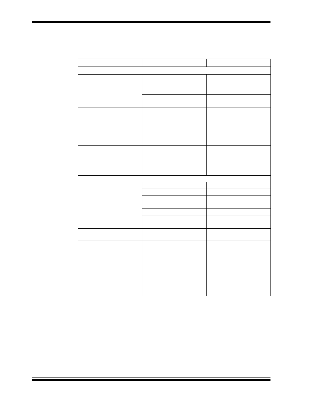
CONVENTIONS USED IN THIS GUIDE
This manual uses the following docum entat io n conven tion s:
DOCUMENTATION CONVENTIONS
Description Represents Examples
Arial font:
Italic chara c ters Referenced books MPLAB
Emphasized text ...is the only compiler...
Initial caps A window the Output window
A dialog the Settings dialog
A menu selection select Enable Programmer
Quotes A field name in a window or
dialog
Underlined, italic text with
right angle bracket
Bold characters A dialog button Click OK
N‘Rnnnn A number in verilog format,
Text in angle brac kets < > A key on the keyboard Press <Enter>, <F1>
Courier New font:
Plain Courier New Sample source code #define START
Italic Courier New A variable argument file.o, where file can be
Square brackets [] Optional arguments mcc18 [options] file
Curly braces and pipe
character: { | }
Ellipses... Replaces r epeated text var_name [,
A menu path File>Save
A tab Click the Power tab
where N is the tota l number of
digits, R is th e radi x and n is a
digit.
Filenames autoexec.bat
File paths c:\mcc18\h
Keywords _asm, _endasm, static
Command-line options -Opa+, -Opa-
Bit values 0, 1
Constants 0xFF, ‘A’
Choice of mut ually exclus ive
arguments; an OR selection
Represents code supplied by
user
®
IDE User’s Guide
“Save project before build”
4‘b0010, 2‘hF1
any valid filename
[options]
errorlevel {0|1}
var_name...]
void main (void)
{ ...
}
WARRANTY REGISTRATION
Please complete the enclosed Warranty Registration Card and mail it promptly.
Sending in the Warranty Registration Card entitles users to receive new product
updates. Interim software releases are available at the Microchip web site.
DS52078A-page 10 2012 Microchip Technology Inc.
Page 11

RECOMMENDED READING
This user’s guide describes how to use the Digital Power Starter Kit. The device-specific
data sheets contain current information on programming the specific microcontroller or
digital signal controller devices. The following Microchip documents are available and
recommended as supplemental reference resources:
MPLAB® C Compiler for PIC24 MCUs and dsPIC® DSCs User’s Guide
(DS51284)
This comprehensive guide describes the usage, operation and features of Microchip’s
MPLAB C compiler (formerly MPLAB C30) for use with 16-bit devices.
MPLAB® IDE User’s Guide (DS51519)
This user’s guide describes how to set up the MPLAB IDE software and use it to create
projects and program devices.
MPLAB X IDE User’s Guide (DS52027)
This document describes how to set up the MPLAB X IDE software and use it to create
projects and program devices.
Readme Files
Preface
For the latest information on using the Digital Power Starter Kit Board, read the
Readme.txt text file in the Readme subdirectory of the MPLAB IDE installation directory
from the Digital Power Start er Kit co de ex am pl e. T he Read me fil e co ntains update
information and kn own issu es t ha t may no t be inclu de d in th is u ser’s g uide.
dsPIC33FJ06GS001/101A/102A/202A and dsPIC33FJ09GS302 Dat a Sheet
(DS75018)
Refer to this document for detailed information on this family of dsPIC33F SMPS Digital
Signal Controllers (D SCs). Reference information found in this data sheet includes:
• Device memory maps
• Device pinout and packaging details
• Device electrical speci fic ati on s
• List of peripherals included on the devices
dsPIC33F/PIC24H Family Reference Manual Sections
Family Reference Manual (FRM) sections are available, which explain the operation of
the dsPIC
specifics of each device family are discussed in the individual family’s device
data sheet.
®
DSC and PIC24H MCU family architecture and peripheral modules. The
dsPIC33F Flash Programming Specification for Devices with Volatile
Configuration Bits (DS70659)
Refer to this document for information on instruction sets and firmware development.
Microchip SMPS Resources
• AN1114 “Switch Mode Power Suppl y (SMPS) Topologies (Part I)” (DS01114)
• AN1207 “Switch Mode Power Supply (SMPS) Topologies (Part II)” (D S01 207 )
• TB062 “Frequently Asked Questions (FAQs) About dsPIC
(DS93062)
To obtain any of these documents, visit the Microchip web site at www.microchip.com.
2012 Microchip Technology Inc. DS52078A-page 11
®
DSC SMPS Devices”
Page 12

Digital Power Starter Kit User’s Guide
THE MICROCHI P WEB SITE
Microchip provides online support via our web site at www.microchip.com. This web
site is used as a means to make files and information easily available to customers.
Accessible by using your favorite Internet browser, the web site contains the following
information:
• Product Support – Data sheets and errata, application notes and sample
programs, design resources, user’s guides and hardware support documents,
latest software releases and archived software
• General Technical Support – Frequently Asked Questions (FAQs), technical
support requests, online discussion groups, Microchip consultant program
member listin g
• Business of Microchip – Product selector and ordering guides, latest Microchip
press releases, listing of seminars and events, listings of Microchip sales offices,
distributors and factory representatives
DEVELOPMENT SYSTEMS CUSTOMER CHANGE NOTIFICATION SERVICE
Microchip’s customer notification service helps keep customers current on Microchip
products. Subscribers will receive e-mail notification whenever there are changes,
updates, revisions or errata related to a specified product family or development tool of
interest.
To register, access the Microchip web site at www.microchip.com, click on Customer
Change Notification and follow the registration instructions.
The Development Systems product group categories are:
• Compilers – The latest information on Microchip C compilers and other language
tools. These include the MPLAB
assemblers; MPLINK™ and MPLAB 16-bit object linkers; and MPLIB™ and
MPLAB 16-bit object librarians.
• Emulators – The latest information on the Microchip MPLAB REAL ICE™
in-circuit emulator.
• In-Circuit Debuggers – The latest information on the Microchip in-circuit
debugger, MPLAB ICD 3.
• MPLAB IDE – The latest information on Microchip MPLAB IDE, the Windows
Integrated Development Environment for development systems tools. This list is
focused on the MPLAB IDE, MPLAB SIM simulator, MPLAB IDE Project Manager
and general editing and debugging features.
• Programmers – The latest information on Microchip programmers. These include
the MPLAB PM3 device programmer and the PICkit™ 3 development
programmers.
®
C compiler; MPASM™ and MPLAB 16-bit
®
DS52078A-page 12 2012 Microchip Technology Inc.
Page 13

CUSTOMER SUPPORT
Users of Microchip products can receive assistance through several channels:
• Distributor or Representative
• Local Sales Office
• Field Application Engineer (FAE)
• Technical Support
Customers should contact their distributor, representative or field application engineer
(FAE) for support. Local sales offices are also available to help customers. A listing of
sales offices and locations is included in the back of this document.
Technical support is available through the web site at: http://support.microchip.com
DOCUMENT REVISION HISTORY
Revision A (June 2012)
This is the initial released version of the document.
Preface
2012 Microchip Technology Inc. DS52078A-page 13
Page 14

Digital Power Starter Kit User’s Guide
NOTES:
DS52078A-page 14 2012 Microchip Technology Inc.
Page 15

This chapter introduces the Digital Power Starter Kit and provides an overview of its
features. The topics covered include:
• Kit Contents
• Starter Kit Functionality and Features
• Electrical Specifications
1.1 OVERVIEW
Modern power supplies are becoming smaller, more efficient, more flexible and less
expensive. These desirable enhancements have come about as Digital Signal Controllers (DSCs) are incorporated into Switch Mode Power Supply (SMPS) designs. The
board provided in the kit is intended to introduce and demonstrate the capabilities and
features of Microchip SMPS families of devices. The Digital Power Starter Kit features
an on-board programmer/debugger, which eliminates the need for any additional
programmer or hardware interface.
The software for the demonstration application that is preprogrammed into the onboard dsPIC33F Digital Signal Controller (DSC) is available for download from the
Microchip web site at: http://www.microchip.com.
DIGIT AL POWER STARTER KIT
USER’S GUIDE
Chapter 1. Introduction
Note: Refer to the Readme file provided with the Digital Power Starter Kit demon-
1.2 KIT CONTENTS
The Digital Power Starter Kit contains the following:
• Digital Power Starter Kit Board
• 9V Power Supply
•USB Cable
Note: If you are missing any part of the kit, contact a Microchip sales office for
stration software for instructions on how to run the demonstration application.
Refer to the Information Sheet that is provided with the starter kit package for
additional resources and instructions on how to use the starter kit for
programming and debugging appli ca tio n software .
assistance. A list of worldwide Microchip offices for sales and service is
provided at the end of this document.
2012 Microchip Technology Inc. DS52078A-page 15
Page 16

Digital Power Starter Kit User’s Guide
VDD
VIN
5k
5k
Resistive
Load
VFB Buck
VIN
PWM1L
PWM1H
PWM2H
Current Sense
Buck
VFB Buck
SW1
Resistive
Load
VFB Boost
PWM2L
VIN
PWM4H
AN0
AN1
AN2
AN3
AN4
AN6
Current Sense
Boost
Vin_FB
RB8
AN5
Temperature
Sensor
AN7
On-Board
Debugger
Voltage/Current/
Temperature/Fault
LCD
USB
PC
dsPIC33FJ09GS302
VFB Boost
1.3 STARTER KIT FUNCTIONALITY AND FEATURES
The Digital Power Starter Kit is a power supply board that consists of one independent
DC/DC synchronous Buck converter and one independent DC/DC Boost converter.
Figure 1-1 illustrates a high-level block diagram of the Starter Kit.
The Digital Power Starter Kit provides closed-loop Proportional-Integral-Derivative
(PID) control in the software to maintain the desired output voltage level. The dsPIC
DSC device provides the necessary memory and peripherals for A/D conversion, PWM
generation, analog comparison and general purpose I/O, preventing the need to
perform these functions in external circuitry.
SMPS dsPIC DSC devices are specifically designed to provide low-cost and efficient
control for a wide range of power supply topologies. The specialized peripherals facilitate
closed-loop feedback control of switch mode power supplies, providing communication
for remote monit o rin g an d supe r vis ory co nt ro l.
The dsPIC33F SMPS family of devices provide the following features:
• Integrated program and data memory on a single chip
• Ultra-fast interrupt response time with interrupt priority logic
• Up to 2 Msps, on-chip ADC with Successive Approximation Register (SAR), an d
three Sample-and-Hold (S&H) circuits.
• Three independent, high-resolution PWM generators, specially designed to support
different power topologies
• Two high-speed analog comparators for control loop implementation and system
protection
• On-chip system communications (I
• On-chip fast RC oscillator for lower system cost
• High-current sink/source for PWM pins (16 mA/16 mA)
• CPU performance (40 MIPS)
• Extensive power-saving features
2
C™/SPI/UART)
®
FIGURE 1-1: DIGITAL POWER STARTER KIT SYSTEM DIAGRAM
DS52078A-page 16 2012 Microchip Technology Inc.
Page 17

Introduction
1.3.1 Power Stages
• One synchronous Buck converter power stage
• One Boost converter pow er stage
• Voltage/current measurement and display for digital controlled Buck converter
• Voltage/current measurement and display for digital controlled Boost converter
• MOSFET controlled 5W resistive load on Buck Converter Output (BUCK_Out)
• MOSFET controlled 5W resistive load on Boost Converter Output (BOOST_Out)
1.3.2 Additional Features
• 5 kOhm Potentiometers (P1 and P2), used to adjust the duty cycle of the
load resistors
• On-board temperature sensor, located near the resistive load; this enables the user
to program a temperature protection limit
• Input voltage sense, used to detect under/overvoltage conditions
• Connector for PICkit Serial Analyzer (J3)
• LED power-on indicator (D1)
• LED output voltage indicators (D5 and D12)
• LCD used to display voltage, current, temperature and Fault conditions
1.3.3 Start er Kit Power
• +9V power connector (J2) supplies power to the Digital Power Starter Kit
• USB connection jack (J5) supplies power/connection to the on-board debugger
• Buck and Boost converters are both operated in Voltage mode (default), but can
also be reprogrammed to operate in Average Current or Peak Current Control mode
2012 Microchip Technology Inc. DS52078A-page 17
Page 18

Digital Power Starter Kit User’s Guide
1.4 ELECTRICAL SPECIFICATIONS
TABLE 1-1: DC INPUT RATING (J2)
Parameter Minimum Typical Maximum Unit
Voltage 7.0 9 11 V
Current 1 — — A
TABLE 1-2: BUCK CONVERTER ELECTRICAL SPECIFICATIONS
Parameter Minimum Typical Maximum Unit
Output Voltage (default programmed) — 3.3 — V
Output Voltage (programmable range) 1.2 — 4.5 V
Output Voltage Ripple — 50 — mV (pk-pk)
Output Current — — 1.5 A
Load Regulation:
V
OUT = 3.3V, IOUT = 0.02-1.5A, VIN = 9V
Switching Frequency — 350 — kHz
Output Power — — 5 W
TABLE 1-3: BOOST CONVERTER ELECTRICAL SPECIFICATIONS
Parameter Minimum Typical Maximum Unit
—50—mV/A
Output Voltage (default programmed) — 15 — V
Output Voltage (programmable range) 11 — 18 V
Output Voltage Ripple — 100 — mV (pk-pk)
Output Current — — 0.4 A
Load Regulation:
V
OUT = 15V, IOUT = 0.02-0.3A, VIN = 9V
Switching Frequency — 350 — kHz
Output Power — — 5 W
—50—mV/A
DS52078A-page 18 2012 Microchip Technology Inc.
Page 19

This chapter describes the hardware components of the Digital Power Starter Kit.
1
2
4
5
3
6
7
8
Topics covered include:
• Top Assembly
• Signal Configuration
• Application Components
• Board Connectors
• Indicators and Human Interfaces
• Test Points
• Power Rating of Converter Stages
• Programmer/Debugger
2.1 TOP ASSEMBLY
The top and bottom assembly of the board is shown in Figure 2-1 and Figure 2-2.
Table 2-1 and Table 2-2 provide a description of the components.
DIGIT AL POWER STARTER KIT
USER’S GUIDE
Chapter 2. Hardware
FIGURE 2-1: DIGITAL POWER STARTER KIT (TOP VIEW)
2012 Microchip Technology Inc. DS52078A-page 19
Page 20

Digital Power Starter Kit User’s Guide
1
2
3
4
5
6
TABLE 2-1: DIGITAL POWER STARTER KIT COMPONENTS (TOP)
Number Description
1 dsPIC33FJ09GS302 Digital Signal Controller (DSC) (U3)
2 9V Power Connector (J2)
3 2x16 Character LCD
4 Boost Converter Stage
5 Buck Converter Stage
6 Push Button (SW1)
7 Potentiometers (P1 and P2)
8 Voltage Regulator (3.3V)
FIGURE 2-2: DIGITAL POWER STARTER KIT (BOTTOM VIEW)
TABLE 2-2: DIGITAL POWER STARTER KIT COMPONENTS (BOTTOM)
Number Description
1 Voltage Regulator (5V)
2 On-Board Programmer/Debugger
3 Programmer/Debugger USB Connector (J5)
4 Buck Converter Resistive Load
5 Boost Converter Resistive Load
6 On-Board Temperature Sensor
DS52078A-page 20 2012 Microchip Technology Inc.
Page 21

2.2 SIGNAL CONFIGURATION
Table 2-3 provides a full list of the dsPIC33FJ09GS302 DSC connections and a brief
functional description of the pins used in the Digital Power Starter Kit.
TABLE 2-3: dsPIC33FJ09GS302 CONFIGURATION DETAILS
Digital Power Starter Kit
Signal Label
Pin
#
dsPIC33FJ09GS302
Device Pin Name
Hardware
Description/Function
ICSP_MCLR_VPP_Target 1 MCLR
CS_BUCK 2 AN0/CMP1A/RA0 Analog – Buck Current Sense
VFB_BUCK 3 AN1/CMP1B/RA1 Analog – Buck Vo ltage Feedback
CS_BOOST 4 AN2/CMP1C/CMP2A/RA2 Analog – Boost Current Sense
VFB_BOOST 5 AN3/CMP1D/CMP2B/RP0/CN0/RB0 Analog – Boost Voltage Feedback
VIN_FB 6 AN4/ISRC4/CMP2C/RP9/CN9/RB9 Analog – Input Voltage Feedback
EXT POT2 7 AN5/ISRC3/CMP2D/RP10/CN10/RB10 Analog – 5k Potentiometer
—8VSS Ground
EXT POT1 9 OSC1/CLKI/AN6/ISRC2/RP1/CN1/RB1 Analog – 5k Potentiometer
Temp_Sensor 10 OSC2/CLKO/AN7/ISRC1//RP2/CN2/RB2 Analog – Temperature Sensor
PGD2 11 PGED2/DACOUT/INT0/RP3/CN3/RB3 Data I/O pin for programming/
PGC2 12 PGEC2/EXTREF/RP4/CN4/RB4 Clock Input pin for programming/
—13V
SW 14 PGED3/RP8/CN8/RB8 SW1 Push Button
LCD_Reset 15
LCD_RSelect 16 TDO/RP5/CN5/RB5 LCD Register Select Signal
SCL/TX 17 PGED1/TDI/SCL1/RP6/CN6/RB6 LCD Serial Clock
SDA/RX 18
—19VSS Ground
—20VCAP CPU Logic Filter Capacitor Connection
PWM4H 21 TMS/RP11/CN11/RB11 Boost MOSFET PWM Signal
LCD_CSB 22
Load BUCK 23 PWM2H/RP13/CN13/RB13 Buck-Resistive Load Driver PWM Signal
Load BOOST 24 PWM2L/RP14/CN14/RB14 Boost-Resistive Load Driver PWM
PWM1H 25 PWM1H/RA4 Buck High Side MOSFET PWM Signal
PWM1L 26 PWM1L/RA3 Buck Low Side MOSFET PWM Signal
—27AV
—28AV
DD Positive Supply for peripheral logic and
PGEC3/RP15/CN15/RB15 LCD Active-Low Reset Signal
PGEC1/SDA1/RP7/CN7/RB7 LCD_Data
TCK/RP12/CN12/RB12 LCD Active-Low Chip Select Signal
SS Ground Referen ce for analog modul es
DD Positive Supply for a nalog modules ; this
Master Clear (Reset) Input
debugging Communication Channel 2
debugging Communication Channel 2
I/O pins
Signal
pin must be c onnected at all times
2012 Microchip Technology Inc. DS52078A-page 21
Page 22

Digital Power Starter Kit User’s Guide
2.3 APPLICATION COMPONENTS
Table 2-4 describes the application components that are available on the Digital Power
Starter Kit (see Figure 2-1 and Figure 2-2 for component locations).
TABLE 2-4: APPLICATION COMPONENTS
Component Label Item Description
Top Assembly Components (see Figure 2-1)
dsPIC33FJ09GS302 DSC U3 1 Provides the processing power for the demonstration applica-
tions and application development on the starter kit. The MCU
features 9 Kbytes of Flash program memory and 1 Kbyte of
RAM. The demonstration application uses the MCU device’s
on-chip FRC oscillator with PLL as a clock source.
9V Power Connector J2 2 A 9V power supply powers the dsPIC33FJ09GS302 DSC and
supplies the power to both of the DC/DC converters on the
starter kit. To operate the starter kit, connect the power supply
provided with the starter kit to J2.
2x16 Character LCD LCD1 3 User-programmable 2x16 character LCD.
Boost Converter Stage N/A 4 5W step-up converter (Boost).
Buck Converter Stage N/A 5 5W step-down converter (Buck).
Potentiometer P1 & P2 7 T wo Potentiometers (POTs). Each POT is connected to an analog
input pin of the DSC, providing an analog reference voltage from
3.3V to ground (0V).
Voltage Regulator U2 8 Voltage regulator (3.3V) provides power to the
dsPIC33FJ09GS302 DSC, LCD, push button, potentiometers
and temperature sensor.
Bottom Assembly Components (see
Voltage Regulator U1 1 Voltage regulator (5V) provides power to the 3.3V regulator and
to the Buck stage gate driver (U9).
On-Board Programmer/
Debugger
Programmer/Debugger
USB Connector
Buck Resistive Load N/A 4 MOSFET controlled 2.2 Ohm resistive load (5W max).
Boost Resistive Load N/A 5 MOSFET controlled 48.3 Ohm resistive load (5W max).
On-Board Temperature
Sensor
N/A 2 Controls the programming/debugging operations of the target
dsPIC33FJ09GS302 DSC.
J5 3 Provides power to the programmer/debugger and bidirectional
communication between the host PC and starter kit.
U7 6 The temperature sensor is strategically placed near the load
resistors. It is intended to provide the board temperature to the
DSC and to disable bo th of th e res is tiv e lo ad s if th e tem pe r atu re
exceeds the set limit.
Figure 2-2)
DS52078A-page 22 2012 Microchip Technology Inc.
Page 23

2.4 BOARD CONNECTORS
Table 2-5 describes the hardware connections available on the Digital Power Starter Kit
(see Figure 2-1 and Figure 2-2 for component locations).
TABLE 2-5: HARDWARE CONNECTIONS
Label Hardware Element Description
J1 Connector for PICkit™ Serial Analyzer (not populated).
J2 9V power supply (not populated).
J3 ICSP™ programmer interface connector for programming the
dsPIC33FJ09GS302 DSC.
J4 ICSP programmer interface connector for programming the
PIC24FJ256GB106 MCU USB-to-UART bridge (not populated).
J5 Mini-USB connector provides bidirectional communication between the host
PC and the on-board programmer/debugger.
2.5 INDICATORS AND HUMAN INTERFACES
Table 2-6 describes the user interfaces available on the starter kit.
TABLE 2-6: INDICATORS AND HUMAN INTERFACES
Label Hardware Element Description
SW1 Push button switch, which is connected to the RB8 port pin. When momentarily
pressed, the LCD measurement and board status information is changed.
D1 Power-on status LED, which indicates that the Digita l Power Starter Kit is
powered by the 9V supply.
D14 USB bus indic ator , which in dicates that the de vice is connected to the USB bu s
and the programmer/debugger is powered.
P1 and P2 Two variable resis tors (pote ntiometers). Each pote ntiometer is connected to an
analog input pin, providing an analog reference voltage from 3.3V to ground
(0V).
D12 Buck converter power-on status LED, which indicates when the Buck DC/DC
converter is enabled.
D5 Boost c onv erte r po w er-on status LED, which indicates when the Boost D C/D C
converter is enabled. Because of the Boost conf iguration, this LED wil l be
illuminated when +9V is present at the J2 connector.
LCD1 User-programmable 2x16 character LCD display.
Hardware
2012 Microchip Technology Inc. DS52078A-page 23
Page 24

Digital Power Starter Kit User’s Guide
TP22 TP12TP11
TP13 TP12
TP11
TP17
TP10
TP9
TP14
TP15
TP6
TP1
+9VGND
GND
GND
BOOST_OUT
GND
BUCK_OUT
2.6 TEST POINTS
Table 2-7 describes the test points that are available on the Digital Power Starter Kit.
See Figure 2-3 for test point locations.
TABLE 2-7: TEST POINTS
Test Point Description
+9V 9V Power Supply test point
BUCK_OUT Output Voltage for the Buck Stage test point
BOOST_OUT Output Voltage fo r the Boost Stage test point
TP1 3.3V Supply Voltage test point
TP5 Boost Stage Switch Node test point
TP6 Boost Stage BODE test point
TP9 Buck Stage BODE test point
TP10 Buck Stage Current Sense test point
TP11 Buck Stage High-Side MOSFET Gate Signal test point
TP12 Buck Stage Low-Side MOSFET Gate Signal test point
TP13 Boost Stage MOSFET Gate Signal test point
TP14 Buck Stage Output Voltage Feedback test point
TP15 Boost Stage Output Voltage Feedback test point
TP16 Resistive Load MOSFET Gate Signal (Boost) test point
TP17 Resistive Load MOSFET Gate Signal (Buck) test point
TP22 Buck Stage Switch Node test point
FIGURE 2-3: DIGITAL POWER STAR TER KIT TEST POINT LOCATIONS
DS52078A-page 24 2012 Microchip Technology Inc.
Page 25

2.7 POWER RATING OF CONVERTER STAGES
The Digital Power Starter Kit is designed to be a self-contained power supply board with
variable 5W loads connected to each DC/DC converter.
2.7.1 BUCK CONVERTER
The Buck converter stage is rated for a maximum power output of 5W to the dedicated
on-board resistive load. The output voltage and output current should remain within its
Safe Operating Area (SOA) to avoid damage to the board, as shown in the graph in
Figure 2-4. The output voltage of the Buck converter (BUCK_Out) can be programmed
to be from a 1.2V to 4.5V output, with a default programmed voltage of 3.3V . The hardware gain [5k/(3.3k + 5k)] of the voltage feedback from the BUCK_Out is provided by
the resistor divider network, R97 and R105. Additionally, a 20 Ohm resistor, R90, for
bode plot measurements is also in series with the feedback network. The hardware
gain of the current feedback is provided by the current transformer (T1) with turns ratio
(1:60) and burden resistor, R69.
FIGURE 2-4: BUCK CONVERTER SOA CURVE
Hardware
2012 Microchip Technology Inc. DS52078A-page 25
Page 26

Digital Power Starter Kit User’s Guide
0.00
0.05
0.10
0.15
0.20
0.25
0.30
0.35
0.40
0.45
11 12 13 14 15 16 17 18 19
Output Voltage, V
Output Current, A
2.7.2 Boost Converter
The Boost converter stage is rated for a maximum output power of 5W to the dedicated
on-board resistive load. The output voltage and output current should remain within the
Boost converter Safe Operating Area (SOA) to avoid damage to the board, as shown
in the graph in Figure 2-5. The output voltage of the Boost converter (BOOST_Out) can
be programmed to be from an 11V to 18V output, with a default programmed voltage
of 15V. The hardware gain [20k/(20k + 3.3k)] of the voltage feedback from the
BOOST_Out is provided by the resistor divider network of R41 and R51. Additionally,
a 20 Ohm resistor, R30, for bode plot measurements is also in series with the feedback
network. The hardware gain of the current feedback is provided by the current sense
resistor, R61.
FIGURE 2-5: BOOST CONVERTER SOA CURVE
2.8 PROGRAMMER/DEBUGGER
The Digital Power Starter Kit includes an on-board programmer/debugger circuit that
provides connectivity over USB. This circuit is hard-wired to the dsPIC DSC device to
provide ICSP™ debugging/programming capability.
2.8.1 Programmer/Debugger Components
Table 2-8 describes the programmer/debugger components that are available on the
Digital Power Starter Kit (see Figure2-2 for component locations).
TABLE 2-8: PROGRAMMER/DEBUGGER COMPONENTS
Compone nt Label Item # Description
On-Board Programmer/
Debugger
Programmer/Debugger
USB Connector
DS52078A-page 26 2012 Microchip Technology Inc.
N/A 2 Controls the programming/debugging operations of the target
dsPIC33FJ09GS302 DSC.
J5 3 Provides power to the programmer/debugger, and bidirectional
communication between the host PC and the Digital Power
Starter Kit.
Page 27

Chapter 3. Demonstration Program Operation
The dsPIC33FJ09GS302 Digital Power Starter Kit is preprogrammed with a
demonstration application that illustrates simultaneous Proportional-Integral-Derivative
(PID) control of the output voltage for the two DC/DC converter circuits on board the
Digital Power Starter Kit. This code can be downloaded from the Microchip web site
(www.microchip.com).
This section covers the following topics:
• Program Demonstration
• Code Demonstration
• Other Code Examples
3.1 PROGRAM DEMONSTRATION
The demonstration program provides simultaneous closed-loop control of the output
voltage for both DC/DC converter stages of the Digital Power Starter Kit.
One PID loop controls the Buck converter output voltage (BUCK_Out) at 3.3V. The
other PID loop controls the Boost converter output voltage (BOOST_Out) at 15V.
The PID control scheme consists of the following parameters:
• Proportional Error Gain (P-Gain) – This parameter produces a correction factor
that is proportional to the magnitude of the output voltage error.
• Integral Error Gain (I-Gain) – This parameter uses the cumulative voltage error to
generate a correction factor that eliminates any residual error due to limitations in
offset voltages and measurement resolution.
• Derivative Error Gain (D-Gain) – This parameter produces a correction factor that
is proportional to the rate of change of the output error voltage, which helps the
system respond quickly to changes in system conditions.
The demonstration program requires no manual preparation except to connect 9V
power to the J2 connector.
DIGIT AL POWER STARTER KIT
USER’S GUIDE
2012 Microchip Technology Inc. DS52078A-page 27
Page 28

Digital Power Starter Kit User’s Guide
Start
ADC Interrupt
End
Yes
No
No
Yes
Soft Start
Routine
Disable
Outputs
Does Fault
Condition Exist?
Is Soft
Start Active?
Initialization Routines:
• Peripherals – ADC, PWM, Timers, GPIO,
LCD, etc.
• Variables – PID Gain Terms, Data Buffers
• Interrupts – ADC, Timers
• Set Soft Start Flag
Idle Loop Functions:
• Check VIN
• Check Soft Start Flag
• Check/Reset Fault Timers and Flag
• Measure Temperature and Potentiometer’s Position
• Update LCD Display Information
• Perform Non-Critical Functions (i.e., user application
tasks)
ADC Interrupt Routines:
• Measure VOUT
• Calculate PID Gain Parameters
• Update PWM Duty Cycle
Fault Check Routine
Soft Start Routine
FIGURE 3-1: SMPS DEMONSTRATION PROGRAM FLOW CHART
DS52078A-page 28 2012 Microchip Technology Inc.
Page 29

3.2 CODE DEMONSTRATION
3.2.1 System Initialization
When power is applied to the board, the program starts by executing the following
system initialization routines:
• Peripherals – The required periph erals (PWM, ADC, T i mers and GPIO) are
configured and en abled
• V ariables – Program variables are defined. RAM locations and register usage are
defined and documented
• Constants – Program constants are defined, including reference set points for
both Buck output voltage and Boost output voltage, input voltage, current limits,
Fault conditions, PWM periods and Timer periods
• Interrupts – The ADC and Timer interrupts are set up and enabled
3.2.2 Fault Check
The program checks for input under/overvoltage, output overvoltage and board temperature limit. If a Fault occurs, the PWM outputs are disabled until the Fault condition
is cleared. If no Fault is detected, the program proceeds.
3.2.3 Soft Start
Demonstration Program Operation
The Soft Start routine ramps up the output voltage in a close-loop fashion to bring the
system within the operating range of the PID control loop. This routine ensures that the
output does not overshoot the desired voltage; it also limits the current at start-up.
3.2.4 ADC Interrupt
The ADC interrupt is the heart of the demo program. This routine takes up approximately 75% of the execution time. It performs all the PID calculations and applies any
needed corrections to the output.
Note: The ADC interrupt can occur any time during program execution. The ADC
interrupt takes priority over any other tasks that the program is performing.
3.2.5 System Idle Loop
All auxiliary functions are performed in the system Idle routine. This is the time available
to the CPU while the demo program is waiting for an ADC interrupt. Non-critical
functions can be performed in this loop. During this time the LCD is refreshed, the
potentiometers position, input voltage, Fault timers and Soft Start flag are checked.
3.3 OTHER CODE EXAMPLES
There are several other SMPS code examples available on the Microchip web site.
Refer to the Readme files located in each code example folder for details on what
each code example demonstrates. Check the Microchip web site
(www.microchip.com/SMPS) for the latest updates to the code examples and for
additional code examples.
2012 Microchip Technology Inc. DS52078A-page 29
Page 30

Digital Power Starter Kit User’s Guide
NOTES:
DS52078A-page 30 2012 Microchip Technology Inc.
Page 31

DIGIT AL POWER STARTER KIT
Appendix A. Board Layout and Schematics
FIGURE A-1: DIGITAL POWER STARTER KIT LAYOUT (TOP)
USER’S GUIDE
2012 Microchip Technology Inc. DS52078A-page 31
Page 32

Digital Power Starter Kit User’s Guide
FIGURE A-2: DIGITAL POWER STARTER KIT LAYOUT (BOTTOM)
DS52078A-page 32 2012 Microchip Technology Inc.
Page 33

Board Layout and Schematics
231
J2
GND
10K
R1
GND
+9V
VIN_FB
+3.3V
GND
R3 DNP
R5 DNP
I2CAUX2
R6
DNP
R7
DNP
+3.3V
BAT54S LT1G
3
1
2
D2
DNP
BAT54 S
LT1
G
3
1
2
D3
DN
P
+3.3V
GND
SDA/RX
SCL/TX
R24
DNP
EXT_POT 1
Temp_Sens
Vin_FB
EXT_POT2
CS_BO OST
GND
VFB_BOOST
PGD2
PGC2
+3.3V
SW
LCD_RSElect
SCL/TX
GND
VFB_BUCK
CS_BUC K
AGND
AVDD
PWM1L
PWM1H
Load_BOOST
Load_BUCK
LCD_CSB
GND
SDA/RX
NHD-C0 216CZ -F S W -F BW -3V 3
RST1RS2CSB3SCL4SI5VSS6VDD7VOUT8C1+9C1+10LED+ALED-
K
LCD1
0RR11
0RR13
0RR14
0RR15
0RR18
0RR21
LCD_Reset
LCD_Reset
LCD_RSelect
LCD_CSB
SCL/TX
SDA/RX
GND
+3.3V
GND
GND
GND
2 4
1
3
SW1
10K
R8
0R
R9
GND
+3.3V
SW
P1
5K
P2
5K
+3.3V
+3.3V
GND
GND
EXT_POT1
EXT_POT2
PWM4H
R25
DNP
I2CAUX1
I2CAUX
1
I2CAUX
2
C2
GND
GND
GND
Green
D1
GND
330R
R2
+3.3V
0R
R17
GND
+3.3V
10K
R12
ICSP_MCL R_VPP_TAR GET
12345
6
J3
DNP
ICSP_MCL
R_VPP_TA RG ET
+3.3V
PGC2
PGD2
GND
+3.3V
R22 DN
P
R19 DN P
0RR16
0RR20
GND
1
GND
2
3
TAB(GND)
4
U2
VIN1GND
2
VOUT
3
TAB(GND)
4
U1
MCP1703T-5002
GND
+5V
GND
10 PF
C57
60.4R
0.25W
R2 3
MCLR1AN0/CMP1A/RA02AN1/CMP1B1/RA13AN2/CMP1C/CMP2A/RA24AN3/CMP1D /CMP2B/RP0(1)/CN0/RB05AN4 /I SR C4 /C MP 2C /R P9( 1) /CN 9/R B96AN5/I SRC3/CM P2D/RP10(1) /CN10/RB107OSC1/CL KI /AN6/ISRC2/ RP1(1) /CN1/RB19OSC2/CL KO/A N7/ISRC1/ RP2(1)/CN 2/RB210PGED2/DA COUT /INT0/RP 3(1)/CN3/RB311PGEC2/EX T REF /R P4(1)/CN4/RB 412VDD
13
VSS
8
PGED3/RP 8(1)/CN8/R B8
14
PGEC3/R P15/CN15/
RB1
5
15
TDO
/RP5(1
)/CN5/RB 5
16
PGED1/TDI/SCL1/RP6(1)/CN 6
/
RB6
17
PGEC1/S DA1/RP7(1)/C N7/RB7
18
VSS
19
VCAP
20
TMS/RP 11(1)/CN11/R B11
21
TCK/RP
12(1)/CN12/RB
12
22
PWM2H/R P13(1)/CN13/ RB13
23
PWM2L/RP 14(1)/CN14/RB14
24
PWM1H/RA4
25
PWM1L/RA 3
26
AVSS
27
AVDD
28
U3
TP1
TP 19
+9V
FID2 FID3 FID4
1
VDD2GND
3
456
J1
DNP
BAT54 SLT1G
3
1
2
D15
+3.3V
GND
BAT54S L T1
G
3
1
2
D16
+3.3V
GND
L3
R4
2.21K
TP4
10 PF
VIN VOUT
MCP1703-3302E/DB
C3
0.1 PF
C4
10 PF
C1
0.01 PF
C5
0.01 PF
C6
0.1 PF
PICkit™ 2
C11
0.1 PF
dsPIC33FJ09GS302
C8
0.1 PF
C7
0.1 PF
C4
10 PF
C10
1 PF
C9
1
PF
C12
1 PF
C13
0.1 PF
FIGURE A-3: DIGITAL POWER STARTER KIT SCHEMATIC
2012 Microchip Technology Inc. DS52078A-page 33
Page 34

Digital Power Starter Kit User’s Guide
+9V
GND GND
4
1
2
3
5
Q2
+9V
IN A2GND3IN B
4
OUT B
5
VDD
6
OUT A
7
NC
8
NC
1
U4
3.30K
R58
GND
5.1
R52
1/8W
GND
10K
R57
20R
R30
3.30K
R51
10K
R35
Green
D5
GND
20.0K
R41
D4
GND
1K
R59
1K
R63
1K
R60
1K
R64
GND
AVDD
GND
CS_BO OST
PWM4H
NTM S5838N LR2G
4
1
2
3
5
6
7
8
Q1
10K
R40
IN A2GND3IN B
4
OUT B
5
VDD
6
OUT A
7
NC
8
NC
1
U6
+9V
Load_BOOST
Load_BUCK
3.30K
R66
3.30K
R67
GND
Place close to dsPIC® DSC
VFB_BOOST
1
VSS
2
VDD
5
IN-4IN+
3
U5
AGND
C20
DNP
AGND
GND
AGND
60.4R
0.25W
R26
60.4R
0.25W
R27
60.4R
0.25W
R28
60.4R
0.25W
R29
60.4R
0.25W
R31
60.4R
0.25W
R32
60.4R
0.25W
R33
60.4R
0.25W
R34
60.4R
0.25W
R36
60.4R
0.25W
R37
60.4R
0.25W
R38
60.4R
0.25W
R39
60.4R
0.25W
R43
60.4R
0.25W
R44
60.4R
0.25W
R45
60.4R
0.25W
R46
60.4R
0.25W
R47
60.4R
0.25W
R48
60.4R
0.25W
R49
60.4R
0.25W
R50
18 pF
C24
10K
R54
10K
R65
C21
DNP
AVDD
OUT B
0.5R
0.5W
R61
R53
DNP
11R
R42
3.30K
R143
GND
18 pF
C25
TP5
TP6
BOOST_Out
TP2
TP15
TP13
TP16
0R
R56
0R
R62
470 pF
C19
TC4427ACOA
C22
4.7 PF
C23
0.1 PF
MCP6021T-E/OT
TC4427ACOA
C26
0.1 PF
C17
220 PF
C18
1 PF
MCP87050
L1
150 PH
C15
0.1 PF
C16
22 PF
FIGURE A-4: DIGITAL POWER STARTER KIT SCHEMATIC (BOOST CONVERTER)
DS52078A-page 34 2012 Microchip Technology Inc.
Page 35

Board Layout and Schematics
+9V
GND
4
1
2
3
5
6
Q3
+5V
3.30K
R106
3.30K
R107
GND
PWM1H
PWM1L
GND
D9
DNP
R79
5.1R 1/8W
10K
R74
R96
5.1R 1/8W
GND
R91
DNP
C39
DNP
GND
3.30K
R97
20R
R90
Green
D12
GND
NTMS 5838NLR2G
4
1
2
3
5
6
7
8
Q4
10K
R98
4.99K
R105
GND
VFB_BUCK
GND
GND
+3.3 V
Temp_S ens
10K
R104
PHASE
1
PWM_HI2PWM_LO
3
GND
4
LOWDR
5
VCC
6
BOOT
7
HIGHDR
8
U9
C28
DNP
1K
R68
R70
DNP
6
4 7
8
T1
TRANS _CST2 _06 0L
GND
CS_BUC K
18pF
C40
GND
2
VOUT
3
VDD
4
U7
GND
OUT B
2.74R
0.25W
R75
2.74R
0.25W
R76
2.74R
0.25W
R77
2.74R
0.25W
R78
2.74R
0.25W
R80
2.74R
0.25W
R81
2.74R
0.25W
R82
2.74R
0.25W
R83
2.74R
0.25W
R85
2.74R
0.25W
R86
2.74R
0.25W
R87
2.74R
0.25W
R88
2.74R
0.25W
R92
2.74R
0.25W
R93
2.74R
0.25W
R94
2.74R
0.25W
R95
2.74R
0.25W
R99
2.74R
0.25W
R100
2.74R
0.25W
R101
2.74R
0.25W
R102
11R
R71
TP22
TP9
TP10
BUCK_Out
TP3
TP14
R142
DNP
GND
TP11
TP12
TP17
4
1
2
3
5
6
Q5
BAT5 4S LT1G
3
1
2
D7
2.21K
R103
120R
R69
120R
R72
C34
0.1 PF
C33
4.7 PF
C31
220 PF
MCP87050
C29
0.1 PF
MCP9700
C30
0.1 PF
C32
0.1 PF
MCP14700-E/SN
MCP87050
L2
22 PH
C35
6.3V
150 PF
C37
6.3V
150 PF
C38
22 PF
C36
1 PF
FIGURE A-5: DIGITAL POWER STARTER KIT SCHEMATIC (BUCK CONVERTER)
2012 Microchip Technology Inc. DS52078A-page 35
Page 36

Digital Power Starter Kit User’s Guide
NOTES:
DS52078A-page 36 2012 Microchip Technology Inc.
Page 37

NOTES:
2012 Microchip Technology Inc. DS52078A-page 37
Page 38

Worldwide Sales and Service
AMERICAS
Corporate Office
2355 West Chandler Blvd.
Chandler, AZ 85224-6199
Tel: 480-792-7200
Fax: 480-792-7277
Techn ical Su pport:
http://www.microchip.com/
support
Web Address:
www.microchip.com
Atlanta
Duluth, GA
Tel: 678-957-9614
Fax: 678-957-1455
Boston
Westborough, MA
Tel: 774-760-0087
Fax: 774-760-0088
Chicago
Itasca, IL
Tel: 630-285-0071
Fax: 630-285-0075
Cleveland
Independence, OH
Tel: 216-447-0464
Fax: 216-447-0643
Dallas
Addison, TX
Tel: 972-818-7423
Fax: 972-818-2924
Detroit
Farmington Hills, MI
Tel: 248-538-2250
Fax: 248-538-2260
Indianapolis
Noblesville, IN
Tel: 317-773-8323
Fax: 317-773-5453
Los Angeles
Mission Viejo, CA
Tel: 949-462-9523
Fax: 949-462-9608
Santa Clara
Santa Clara, CA
Tel: 408-961-6444
Fax: 408-961-6445
Toronto
Mississauga, Ontario,
Canada
Tel: 905-673-0699
Fax: 905-673-6509
ASIA/PACIFIC
Asia Pacific Office
Suites 3707-14, 37th Floor
Tower 6, The Gateway
Harbour City, Kowloon
Hong Kong
Tel: 852-2401-1200
Fax: 852-2401-3431
Australia - Sydney
Tel: 61-2-9868-67 33
Fax: 61-2-9868-6755
China - Beijing
Tel: 86-10-8569-7 000
Fax: 86-10-8528-2104
China - Chengdu
Te l: 86-28-8665-55 11
Fax: 86-28-8665-7889
China - Chongqing
Tel: 86-23-8980-9 588
Fax: 86-23-8980-9500
China - Hangzhou
Tel: 86-571-2819- 3187
Fax: 86-571-2819-3189
China - Hong Kong SAR
Tel: 852-2401-1200
Fax: 852-2401-3431
China - Nanjing
Tel: 86-25-8473-2 460
Fax: 86-25-8473-2470
China - Qingdao
Tel: 86-532-8502- 7355
Fax: 86-532-8502-7205
China - Shanghai
Tel: 86-21-5407-5 533
Fax: 86-21-5407-5066
China - Shenyang
Tel: 86-24-2334-2 829
Fax: 86-24-2334-2393
China - Shenzhen
Tel: 86-755-8203- 2660
Fax: 86-755-8203-1760
China - Wuhan
Tel: 86-27-5980-5 300
Fax: 86-27-5980-5118
China - Xian
Tel: 86-29-8833-7 252
Fax: 86-29-8833-7256
China - Xiamen
Tel: 86-592-2388138
Fax: 86-592-2388130
China - Zhuhai
Tel: 86-756-3210040
Fax: 86-756-3210049
ASIA/PACIFIC
India - Bangalore
Tel: 91-80-3090-4444
Fax: 91-80-3090-4123
India - New Delhi
Tel: 91-11-4160-8631
Fax: 91-11-4160-8632
India - Pune
Tel: 91-20-2566-1512
Fax: 91-20-2566-1513
Japan - Osaka
Tel: 81-66-152-7160
Fax: 81-66-152-9310
Japan - Yokohama
Tel: 81-45-471- 6166
Fax: 81-45-471-6122
Korea - Daegu
Tel: 82-53-744-4301
Fax: 82-53-744-4302
Korea - Seoul
Tel: 82-2-554-7200
Fax: 82-2-558-5932 or
82-2-558-5934
Malaysia - Kuala Lumpur
Tel: 60-3-6201-9857
Fax: 60-3-6201-9859
Malaysia - Penang
Tel: 60-4-227-8870
Fax: 60-4-227-4068
Philippines - Manila
Tel: 63-2-634-9065
Fax: 63-2-634-9069
Singapore
Tel: 65-6334-8870
Fax: 65-6334-8850
Tai wan - Hsin Chu
Tel: 886-3-5778-366
Fax: 886-3-5770-955
Taiwan - Kaohsiung
Tel: 886-7-536-4818
Fax: 886-7-330-9305
Taiwan - Taipei
Tel: 886-2-2500-6610
Fax: 886-2-2508-0102
Thailand - Bangkok
Tel: 66-2-694-1351
Fax: 66-2-694-1350
EUROPE
Austria - Wels
Tel: 43-7242-2244- 39
Fax: 43-7242-2244-393
Denmark - Copenhagen
Tel: 45-4450-2828
Fax: 45-4485-2829
France - Paris
Tel: 33-1-69-53 -63-20
Fax: 33-1-69-30-90-79
Germany - Munich
Tel: 49-89-627- 144-0
Fax: 49-89-627-144-44
Italy - Milan
Tel: 39-0331-742611
Fax: 39-0331-466781
Netherlands - Drunen
Tel: 31-416-690399
Fax: 31-416-690340
Spain - Madrid
Tel: 34-91-708- 08-90
Fax: 34-91-708-08-91
UK - Wokingham
Tel: 44-118-921-5869
Fax: 44-118-921-5820
11/29/11
DS52078A-page 38 2012 Microchip Technology Inc.
 Loading...