

Page 1

CL88030
230 V
AC
Offline LED Driver
Evaluation Board
User’s Guide
2018 Microchip Technology Inc. DS50002772A
Page 2

Note the following details of the code protection feature on Microchip devices:
YSTEM
CERTIFIED BY DNV
== ISO/TS 16949 ==
• Microchip products meet the specification contained in their particular Microchip Data Sheet.
• Microchip believes that its family of products is one of the most secure families of its kind on the market today, when used in th
intended manner and under normal conditions.
• There are dishonest and possibly illegal methods used to breach the code protection feature. All of these methods, to our
knowledge, require using the Microchip products in a manner outside the operating specifications contained in Microchip’s Data
Sheets. Most likely, the person doing so is engaged in theft of intellectual property.
• Microchip is willing to work with the customer who is concerned about the integrity of their code.
• Neither Microchip nor any other semiconductor manufacturer can guarantee the security of their code. Code protection does not
mean that we are guaranteeing the product as “unbreakable.”
Code protection is constantly evolving. We at Microchip are committed to continuously improving the code protection features of our
products. Attempts to break Microchip’s code protection feature may be a violation of the Digital Millennium Copyright Act. If such acts
allow unauthorized access to your software or other copyrighted work, you may have a right to sue for relief under that Act.
Information contained in this publication regarding device
applications and the like is provided only for your convenience
and may be superseded by updates. It is your responsibility to
ensure that your application meets with your specifications.
MICROCHIP MAKES NO REPRESENTATIONS OR
WARRANTIES OF ANY KIND WHETHER EXPRESS OR
IMPLIED, WRITTEN OR ORAL, STATUTORY OR
OTHERWISE, RELATED TO THE INFORMATION,
INCLUDING BUT NOT LIMITED TO ITS CONDITION,
QUALITY, PERFORMANCE, MERCHANTABILITY OR
FITNESS FOR PURPOSE. Microchip disclaims all liability
arising from this information and its use. Use of Microchip
devices in life support and/or safety applications is entirely at
the buyer’s risk, and the buyer agrees to defend, indemnify and
hold harmless Microchip from any and all damages, claims,
suits, or expenses resulting from such use. No licenses are
conveyed, implicitly or otherwise, under any Microchip
intellectual property rights unless otherwise stated.
Microchip received ISO/TS-16949:2009 certification for its worldwide
headquarters, design and wafer fabrication facilities in Chandler and
Tempe, Arizona; Gresham, Oregon and design centers in California
and India. The Company’s quality system processes and procedures
are for its PIC
devices, Serial EEPROMs, microperipherals, nonvolatile memory and
analog products. In addition, Microchip’s quality system for the design
and manufacture of development systems is ISO 9001:2000 certified.
®
MCUs and dsPIC® DSCs, KEELOQ
®
code hopping
QUALITY MANAGEMENT S
Trademarks
The Microchip name and logo, the Microchip logo, AnyRate, AVR,
AVR logo, AVR Freaks, BitCloud, chipKIT, chipKIT logo,
CryptoMemory, CryptoRF, dsPIC, FlashFlex, flexPWR, Heldo,
JukeBlox, KeeLoq, Kleer, LANCheck, LINK MD, maXStylus,
maXTouch, MediaLB, megaAVR, MOST, MOST logo, MPLAB,
OptoLyzer, PIC, picoPower, PICSTART, PIC32 logo, Prochip
Designer, QTouch, SAM-BA, SpyNIC, SST, SST Logo,
SuperFlash, tinyAVR, UNI/O, and XMEGA are registered
trademarks of Microchip Technology Incorporated in the U.S.A.
and other countries.
ClockWorks, The Embedded Control Solutions Company,
EtherSynch, Hyper Speed Control, HyperLight Load, IntelliMOS,
mTouch, Precision Edge, and Quiet-Wire are registered
trademarks of Microchip Technology Incorporated in the U.S.A.
Adjacent Key Suppression, AKS, Analog-for-the-Digital Age, Any
Capacitor, AnyIn, AnyOut, BodyCom, CodeGuard,
CryptoAuthentication, CryptoAutomotive, CryptoCompanion,
CryptoController, dsPICDEM, dsPICDEM.net, Dynamic Average
Matching, DAM, ECAN, EtherGREEN, In-Circuit Serial
Programming, ICSP, INICnet, Inter-Chip Connectivity,
JitterBlocker, KleerNet, KleerNet logo, memBrain, Mindi, MiWi,
motorBench, MPASM, MPF, MPLAB Certified logo, MPLIB,
MPLINK, MultiTRAK, NetDetach, Omniscient Code Generation,
PICDEM, PICDEM.net, PICkit, PICtail, PowerSmart, PureSilicon,
QMatrix, REAL ICE, Ripple Blocker, SAM-ICE, Serial Quad I/O,
SMART-I.S., SQI, SuperSwitcher, SuperSwitcher II, Total
Endurance, TSHARC, USBCheck, VariSense, ViewSpan,
WiperLock, Wireless DNA, and ZENA are trademarks of
Microchip Technology Incorporated in the U.S.A. and other
countries.
SQTP is a service mark of Microchip Technology Incorporated in
the U.S.A.
Silicon Storage Technology is a registered trademark of Microchip
Technology Inc. in other countries.
GestIC is a registered trademark of Microchip Technology
Germany II GmbH & Co. KG, a subsidiary of Microchip
Technology Inc., in other countries.
All other trademarks mentioned herein are property of their
respective companies.
© 2018, Microchip Technology Incorporated, All Rights Reserved.
ISBN: 978-1-5224-3372-9
e
DS50002772A-page 2 2018 Microchip Technology Inc.
Page 3

CL88030
230 V
OFFLINE LED DRIVER
AC
EVALUATION BOARD USER’S GUIDE
Table of Contents
Preface ........................................................................................................................... 5
Introduction............................................................................................................ 5
Document Layout .................................................................................................. 5
Conventions Used in this Guide ............................................................................ 6
Recommended Reading........................................................................................ 7
The Microchip Website.......................................................................................... 7
Customer Support ................................................................................................. 7
Document Revision History ................................................................................... 7
Chapter 1. Product Overview
1.1 Introduction ..................................................................................................... 9
1.2 CL88030 Overview ......................................................................................... 9
1.3 CL88030 Key Features .................................................................................. 9
1.4 What is the CL88030 230 V
Evaluation Board (ADM00860)? ............................................................. 11
1.5 What the CL88030 230 V
Evaluation Board Kit Contains ................................................................ 13
Offline LED Driver
AC
Offline LED Driver
AC
Chapter 2. Installation and Operation
2.1 Introduction ................................................................................................... 15
2.2 Getting Started ............................................................................................. 16
2.3 Setup Procedure .......................................................................................... 17
2.4 How Does the CL88030 230 V
Evaluation Board Set Work? .................................................................. 18
2.5 Board Testing ............................................................................................... 19
Appendix A. Schematic and Layouts
A.1 Introduction .................................................................................................. 21
A.2 Board Schematic – ADM00860 .................................................................... 22
A.3 Board Schematic – ADM00861 .................................................................... 23
A.4 ADM00860 – Top Silk .................................................................................. 23
A.5 ADM00860 – Top Copper and Silk .............................................................. 24
A.6 ADM00860 – Top Copper ............................................................................ 24
A.7 ADM00860 – Bottom Copper and Silk ......................................................... 25
A.8 ADM00861 – Top Silk .................................................................................. 25
A.9 AMD00861 – Top Copper and Silk .............................................................. 26
A.10 ADM00861 – Top Copper .......................................................................... 26
A.11 ADM00861 – Bottom Copper and Silk ....................................................... 27
Offline LED Driver
AC
Appendix B. Bill of Materials (BOM)........................................................................... 29
2018 Microchip Technology Inc. DS50002772A-page 3
Page 4

CL88030 230 VAC Offline LED Driver Evaluation Board User’s Guide
Appendix C. Plots and Waveforms
C.1 CL88030 230 V
Evaluation Board Typical Waveforms ..................................................... 31
Offline LED Driver
AC
C.2 CL88030 230 V
Offline LED Driver
AC
Evaluation Board Typical Measurements ............................................... 37
Worldwide Sales and Service .....................................................................................41
DS50002772A-page 4 2018 Microchip Technology Inc.
Page 5

CL88030
230 V
OFFLINE LED DRIVER
AC
EVALUATION BOARD USER’S GUIDE
Preface
NOTICE TO CUSTOMERS
All documentation becomes dated, and this manual is no exception. Microchip tools and
documentation are constantly evolving to meet customer needs, so some actual dialogs
and/or tool descriptions may differ from those in this document. Please refer to our website
(www.microchip.com) to obtain the latest documentation available.
Documents are identified with a “DS” number. This number is located on the bottom of each
page, in front of the page number. The numbering convention for the DS number is
“DSXXXXXXXXA”, where “XXXXXXXX” is the document number and “A” is the revision level
of the document.
For the most up-to-date information on development tools, see the MPLAB
Select the Help menu, and then Topics to open a list of available online help files.
®
IDE online help.
INTRODUCTION
This chapter contains general information that will be useful to know before using the
CL88030 230 V
include:
• Document Layout
• Conventions Used in this Guide
• Recommended Reading
• The Microchip Website
• Customer Support
• Document Revision History
DOCUMENT LAYOUT
This document describes how to use the CL88030 230 V
ation Board as a development tool. The manual layout is as follows:
• Chapter 1. “Product Overview” – Important information about the CL88030 230
V
AC
• Chapter 2. “Installation and Operation” – Includes instructions on how to get
started with the CL88030 230 V
detailed description of each function.
• Appendix A. “Schematic and Layouts” – Shows the schematic and layout
diagrams for the CL88030 230 V
• Appendix B. “Bill of Materials (BOM)” – Lists the parts used to build the
CL88030 230 V
• Appendix C. “Plots and Waveforms” – Describes the plots and waveforms for
the CL88030 230 V
Offline LED Driver Evaluation Board. Items discussed in this chapter
AC
Offline LED Driver Evaluation Board.
Offline LED Driver Evaluation Board and a
AC
Offline LED Driver Evaluation Board.
AC
Offline LED Driver Evaluation Board.
AC
Offline LED Driver Evaluation Board.
AC
Offline LED Driver Evalu-
AC
2018 Microchip Technology Inc. DS50002772A-page 5
Page 6
CL88030 230 VAC Offline LED Driver Evaluation Board User’s Guide
CONVENTIONS USED IN THIS GUIDE
This manual uses the following documentation conventions:
DOCUMENTATION CONVENTIONS
Description Represents Examples
Arial font:
Italic characters Referenced books MPLAB® IDE User’s Guide
Emphasized text ...is the only compiler...
Initial caps A window the Output window
A dialog the Settings dialog
A menu selection select Enable Programmer
Quotes A field name in a window or
dialog
Underlined, italic text with
right angle bracket
Bold characters A dialog button Click OK
N‘Rnnnn A number in verilog format,
Text in angle brackets < > A key on the keyboard Press <Enter>, <F1>
Courier New font:
Plain Courier New Sample source code #define START
Italic Courier New A variable argument file.o, where file can be
Square brackets [ ] Optional arguments mcc18 [options] file
Curly brackets and pipe
character: { | }
Ellipses... Replaces repeated text var_name [,
A menu path File>Save
A tab Click the Power tab
where N is the total number of
digits, R is the radix and n is a
digit.
Filenames autoexec.bat
File paths c:\mcc18\h
Keywords _asm, _endasm, static
Command-line options -Opa+, -Opa-
Bit values 0, 1
Constants 0xFF, ‘A’
Choice of mutually exclusive
arguments; an OR selection
Represents code supplied by
user
“Save project before build”
4‘b0010, 2‘hF1
any valid filename
[options]
errorlevel {0|1}
var_name...]
void main (void)
{ ...
}
DS50002772A-page 6 2018 Microchip Technology Inc.
Page 7

RECOMMENDED READING
Preface
This user's guide describes how to use the CL88030 230 V
Evaluation Board. Another useful document is listed below. The following Microchip
document is available and recommended as supplemental reference resource:
• CL88030 Data Sheet - Sequential Linear LED Driver with Four or Six Taps
(DS20006049)
THE MICROCHIP WEBSITE
Microchip provides on-line support via our website at www.microchip.com. This
website is used as a means to make files and information easily available to customers.
Accessible by using your favorite internet browser, the website contains the following
information:
• Product Support – Data sheets, errata, application notes, sample programs,
design resources, user’s guides, hardware support documents, latest software
releases, and archived software
• General Technical Support – Frequently Asked Questions (FAQs), technical
support requests, online discussion groups, Microchip consultant program
member listing
• Business of Microchip – Product selector and ordering guides, latest Microchip
press releases, listing of seminars and events, listings of Microchip sales offices,
distributors and factory representatives
CUSTOMER SUPPORT
Offline LED Driver
AC
Users of Microchip products can receive assistance through several channels:
• Distributor or Representative
• Local Sales Office
• Field Application Engineer (FAE)
• Technical Support
Customers should contact their distributor, representative or Field Application Engineer
(FAE) for support. Local sales offices are also available to help customers. A listing of
sales offices and locations is included in the back of this document.
Technical support is available through the website at:
http://www.microchip.com/support.
DOCUMENT REVISION HISTORY
Revision A (August 2018)
• Initial release of this document.
2018 Microchip Technology Inc. DS50002772A-page 7
Page 8

CL88030 230 VAC Offline LED Driver Evaluation Board User’s Guide
NOTES:
DS50002772A-page 8 2018 Microchip Technology Inc.
Page 9

Chapter 1. Product Overview
1.1 INTRODUCTION
CL88030
230 V
OFFLINE LED DRIVER
AC
EVALUATION BOARD USER’S GUIDE
This chapter provides an overview of the CL88030 230 V
ation Board and covers the following topics:
• CL88030 Overview
• CL88030 Key Features
• What is the CL88030 230 V
• What the CL88030 230 V
1.2 CL88030 OVERVIEW
The CL88030 driver Integrated Circuit (IC) is a sequential linear LED driver, 4-tap
version, targeted to provide a flexible solution to drive LEDs from AC line voltages up
to 277 V
A sequential linear LED driver is an LED driver, operating from an AC voltage source
and comprised of multiple linear current regulators driving various tap points along a
long string of LEDs connected to the rectified AC. High efficiency is achieved by
shutting off upstream regulators when downstream regulators achieve regulation.
The CL88030 is in a DFN-10 package. The power dissipation for this device is much
lower than the CL8800 or CL88020 one, due to the external FETs. The bottom tab is
not necessary for thermal reasons, but it is necessary to provide 11 electrical
connections for the CL88030.
and at high-output powers.
AC
1.3 CL88030 KEY FEATURES
Offline LED Driver Evalu-
AC
Offline LED Driver Evaluation Board (ADM00860)?
AC
Offline LED Driver Evaluation Board Kit Contains
AC
• Scalable:
- AC line voltage limited only by external FETs
- Output power limited only by external FETs
• No Inductors:
- Reduces BOM cost and circuit complexity
• Efficient Operation:
- Typical electrical efficiencies of 80% to 90% across the AC input voltage
range
• No High Frequencies:
- Inherently low-conducted EMI, no need for input filters
• Inherently Dimmer Compatible:
- Works with most leading-edge and trailing-edge phase-cut dimmers
- Requires no special circuitry to detect and to handle dimmers
- May require an RC network across the AC line to provide adequate TRIAC
latching current
• Two Versions - 4-tap (CL88030) and 6-tap (CL88031):
- Higher taps increase efficiency and lower Total Harmonic Distortion (THD)
- Fewer taps reduce costs
2018 Microchip Technology Inc. DS50002772A-page 9
Page 10

CL88030 230 VAC Offline LED Driver Evaluation Board User’s Guide
• Reduced Output Ripple (optional):
- An external capacitor with four diodes provides lower output ripple
- Strobing occurs at low line
- Provides continuous power to the driver
• Active Line Regulation:
- Active circuitry provides better regulated output power over variations in AC
line voltage
- –12%/+0% line regulation typical
- Prevents driver from overheating at high AC line voltages
- Prevents excessive currents at low line
- Required for reasonable line regulation and efficient operation, given only four
or six taps
- If unused, the ALR pin is left open in the application
• Overtemperature Protection (OTP), Optional:
- An inexpensive external NTC thermistor provides remote temperature
sensing. The thermistor may be near the LEDs to provide nearly direct
monitoring of LED temperature.
- OTP is linear (no on/off cycling)
- A widely available, 470 k NTC provides an 85°C maximum temperature
- Temperature adjustable via selection of NTC thermistor resistance
- If unused, the OTP pin is tied to BIAS
• Two Current-setting Resistors:
- Different hold-up and direct AC currents lower the THD and output ripple
- Tap current ratios internally set
- Reduces component count
- Fewer pins
- Simplifies application design
- Single-point current control for reduced EMI
DS50002772A-page 10 2018 Microchip Technology Inc.
Page 11
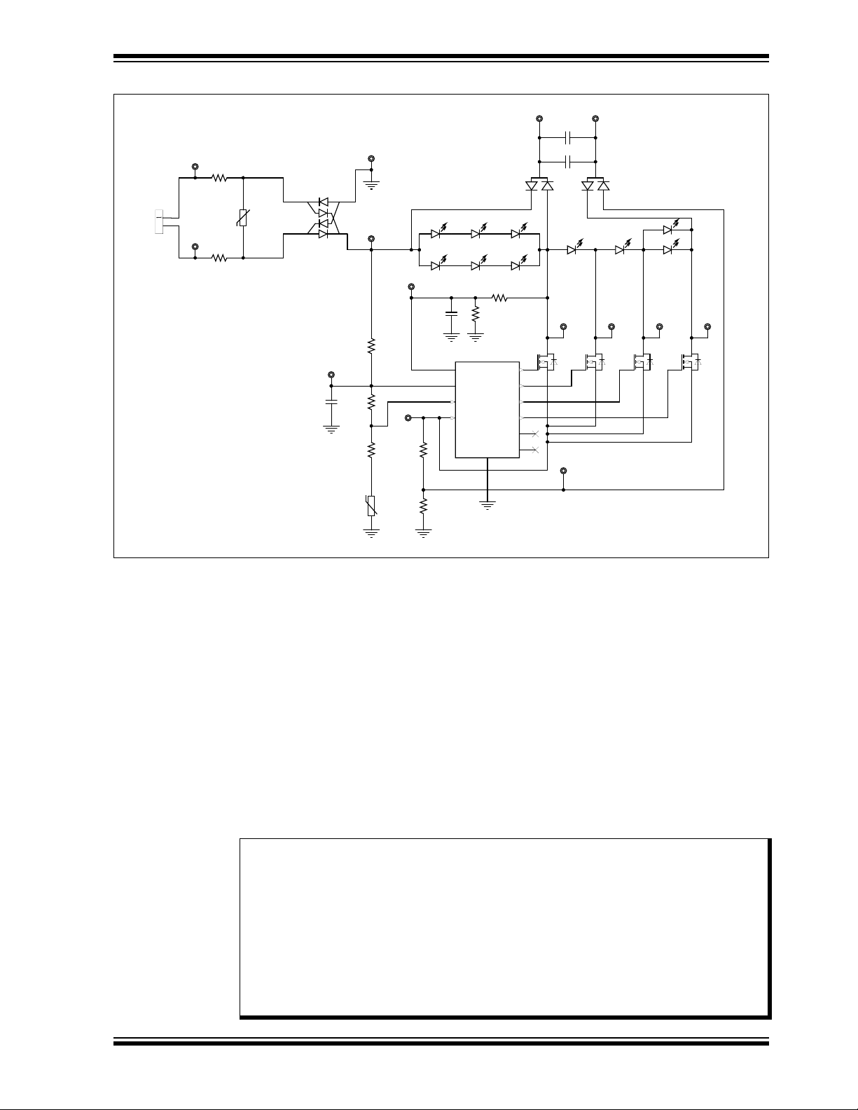
Product Overview
GND
GND
GND
GND
1 2
CRPL2
15uF
1 2
CRPL1
15uF
GND
1
2
3
MMBD1503A
D3
1
2
3
MMBD1503A
D2
387V
600V
1A
GND
7.5R
Rset1
3.24R
Rset2
28k
Ralr2
221k
Rotpu
200k
Rbias
4.7uF
Cbias
4.7uF
Calr
TP1
TP2
TP9 TP10
TP6 TP7TP5 TP8
TP3
TP4
TP14
TP13
TP12
TP11
1
2
J1
MOV1
4 1
23
~
~
+
-
D1
10R
Rtp1
10R
Rtp2
0R
Rotpl
1M
Ralr1
-t
470k
Rntc
GND
)
2
1
3
Q1
2
1
3
Q2
2
1
3
Q3
2
1
3
Q4
GT1
1
GT2
2
GT3
3
GT4
4
NC
5
NC
6
CS
7
OTP
8
BIAS
9
ALR
10
GND
11
CL88030
IC1
(24.8V, 10..200mA
FIGURE 1-1: Typical CL88030 230 V
1.4 WHAT IS THE CL88030 230 V
Offline LED Driver Evaluation Board Circuit.
AC
OFFLINE LED DRIVER EVALUATION
AC
BOARD (ADM00860)?
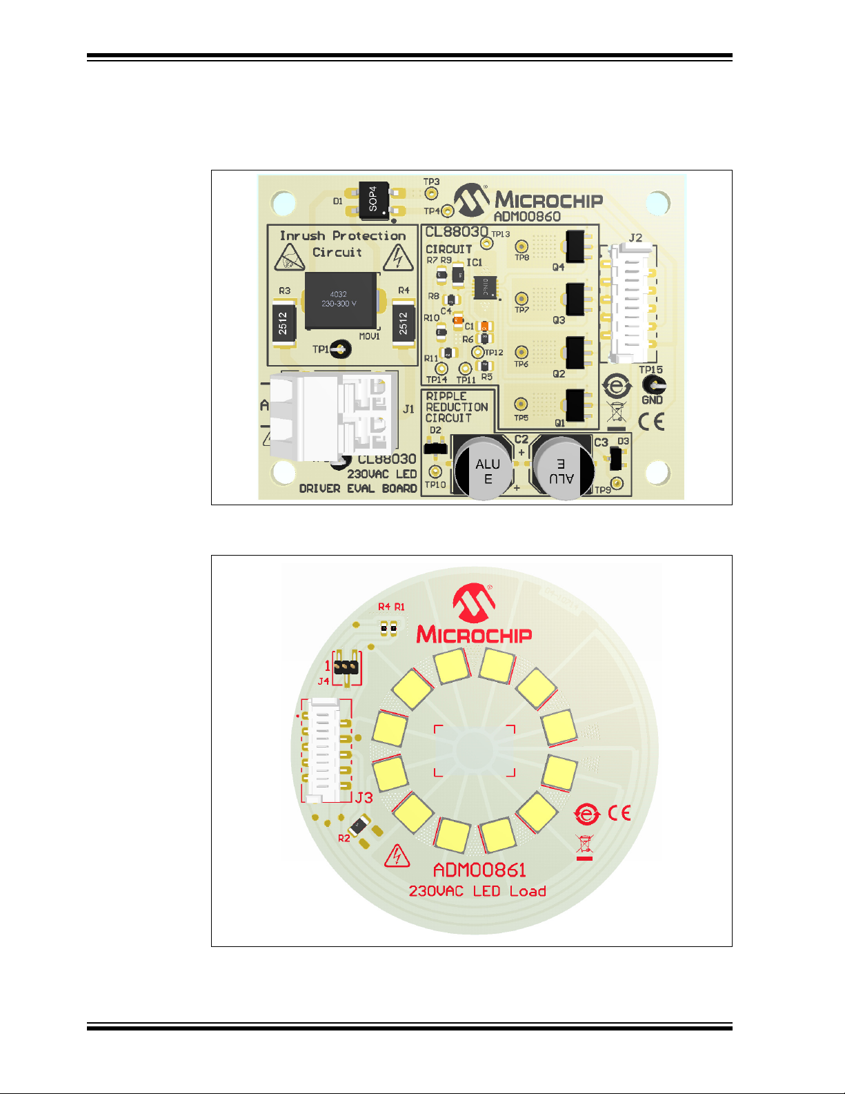
The CL88030 230 V
designated LED Load Board (ADM00861) represent a complete solution for a LED
lighting application, powered directly from the 230 V
Technology's CL88030 sequential linear LED driver. The application achieves efficient
operation without magnetics or conventional switching techniques and is a flexible
solution that allows users to design and test their own LED Load. The available LED
Load is made with 12 LEDs. Since no high frequencies are present, it exhibits inherently low conducted and radiated EMI without the need of input filters or shielding.
Because the current through the LEDs follows the AC input voltage, Power Factor
Correction (PFC) circuitry is not needed. With the addition of an RC network, the
CL88030 is compatible with both leading-edge and trailing-edge dimmers.
Note: The LED Load (ADM00861) is provided on a double-layer 60 mm diameter
FR4 (0.6 mm thick) PCB, ready to be mounted on a pin-fin heat sink. The
kit includes a black anodized pin-fin heat sink and a double-sided adhesive
thermal tape necessary to mount the LED Load on it. The LED Load is also
developed to be used with another LED Driver board from the CL88 series
(ADM00866, CL8800 LED Driver Board), so it is equipped with a selectable
(by means of a jumper) NTC or PTC thermistor, making Overtemperature
Protection (OTP) possible. For the current application, the selection activates the NTC thermistor by mounting the jumper between positions 2 and
3 of the J4 header.
Offline LED Driver Evaluation Board (ADM00860) and a
AC
line and based on Microchip
AC
2018 Microchip Technology Inc. DS50002772A-page 11
Page 12
CL88030 230 VAC Offline LED Driver Evaluation Board User’s Guide
The LED Driver PCB (ADM00860) is made on a 1.6 mm standard double-layer FR4.
The kit includes a 10-wire flat cable to connect the LED Driver Board to the LED Load.
All circuitry and hardware are provided, along with transient protection and OTP. Plug
into a 230 V
outlet (50 Hz or 60 Hz) to get started.
AC
FIGURE 1-2: CL88030 230 V
(ADM00860) – Top View.
Offline LED Driver Evaluation Board
AC
FIGURE 1-3: CL88030 LED Load Board (ADM00861) – Top View.
DS50002772A-page 12 2018 Microchip Technology Inc.
Page 13

Product Overview
1.5 WHAT THE CL88030 230 V
KIT CONTAINS
The CL88030 230 V
• CL88030 230 V
• 10-wire interconnection flat cable
• 4 nylon stand-offs with corresponding screws
• Important Information Sheet
Note: The CL88030 LED Load Board (ADM00861) is available for purchase from
www.microchipdirect.com. The CL88030 LED Load Board kit includes:
• CL88030 LED Load Board (ADM00861)
• LED Load pin-fin heat sink
• Thermal double-sided adhesive tape
• Important Information Sheet
AC
OFFLINE LED DRIVER EVALUATION BOARD
AC
Offline LED Driver Evaluation Board kit includes:
AC
Offline LED Driver Evaluation Board (ADM00860)
2018 Microchip Technology Inc. DS50002772A-page 13
Page 14

CL88030 230 VAC Offline LED Driver Evaluation Board User’s Guide
NOTES:
DS50002772A-page 14 2018 Microchip Technology Inc.
Page 15

Chapter 2. Installation and Operation
2.1 INTRODUCTION
CL88030
230 VAC OFFLINE LED DRIVER
EVALUATION BOARD USER’S GUIDE
The CL88030 230 V
string of inexpensive, low-current LEDs directly from the AC mains. A basic driver circuit consists of the CL88030, six resistors, four FETs and a bridge rectifier. Two to four
additional components are optional for various levels of transient protection, also with
a low-price NTC to assure remote OTP. No capacitors, EMI filters or power factor
correction circuits are needed.
The operation principle is identical to the CL88020 one, the difference being the output
FETs that are outside the IC and so, the power capability of the application is higher
and the input/output capability is also higher. A string of series/parallel LEDs is tapped
at four locations. Four linear current regulators sink current at each tap through a single
control point and are sequentially turned on and off. High efficiency is achieved by shutting off upstream regulators when downstream regulators achieve regulation. This
makes controlling overall input current easier than trying to control multiple current
paths, thereby tracking the input sine wave voltage. Voltage across each regulator is
minimized when conducting, providing high efficiency. It implements a self-commutation technique using only the tap currents. This technique inherently provides smooth
transitions from one regulator to the next, without relying on tap voltages or the rectified
AC to coordinate the transitions. The current waveform can be tailored to optimize for
input voltage range, active line/load regulation, output power/current, efficiency, power
factor, THD, dimmer compatibility and LED utilization. With the addition of a Resistor-Capacitor (RC) network, the driver is compatible with a wider range of phase-cut
dimmers. The data sheet includes a description of the driver’s operation mode, with
design guidelines and examples. Additional topics include optimization/tradeoffs in performance (output power, efficiency, LED utilization, driver dissipation, output ripple,
component selection, input current THD, PF and line regulation). Transient protection,
OTP and ripple reduction circuit are also covered. Explanations are provided for tap
sequencing, active line regulation and OTP.
Offline LED Driver evaluation board is designed to drive a long
AC
2.1.1 Board Features
The CL88030 230 V
following features:
• Input Voltage: 230 V
• Typical Output Capability: up to 130 mA
• Efficiency: over 83%
• Maximum Output Power: 14W (it depends on the cooling provided)
The CL88030 LED Load board (ADM00861) has the following features:
• 12 Osram Duris
• A 10-wire Flat Cable Input Connector
• One NTC for OTP
2018 Microchip Technology Inc. DS50002772A-page 15
Offline LED Driver evaluation board (ADM00860) has the
AC
+/-15%, 50/60 Hz
rms
®
S8 family LEDs (GW P9LR31.EM) Grouped in Four Taps
Page 16

CL88030 230 VAC Offline LED Driver Evaluation Board User’s Guide
2.2 GETTING STARTED
The CL88030 230 V
and demonstrate the CL88030 LED Driver.
Offline LED Driver evaluation board is fully tested to evaluate
AC
WARNING
The ADM00860 source board and ADM00861 LED Load board do NOT provide electrical
isolation between the AC line and the lamp circuitry. Dangerous voltages are present
when connected to the AC line. Exercise caution!
Consider the following recommendations before starting the setup process:
• Place the CL88030 LED Driver evaluation board and the LED Load assembly on
a non-conductive surface when connected to the AC line.
• Do not come into contact with any of the two demonstration unit boards while they
are connected to the AC line.
• Disconnect the demonstration units from the AC line before performing any work
on any of them.
• Do not connect instruments having earth-referenced inputs, such as most
oscilloscopes (use isolation transformers).
• It is suggested that utility power for testing is provided from an AC source with a
floating output, and that differential voltage probes are used.
Failure to adhere to these guidelines may result in damage to the demo unit, the test
instruments, and/or can put in danger the person conducting the tests.
2.2.1 Prerequisites
Since the power of the application is about 15 watts, for a continuous operation of the
LED Load (more than 30s), attach the provided heat sink using the double-sided adhesive thermal tape by following these steps:
1. Before you start, make sure that the surface of the heat sink and of the PCB are
dry and clean (use cotton made smooth material to clean if needed).
2. Detach the protection foil on the thermal tape from one side.
3. Attach the open portion of the thermal tape to the base of the heat sink.
4. Detach the second protection foil from the thermal tape.
5. Attach the PCB (ADM00861) to the heat sink.
6. Slowly press the top of the PCB to be sure that the thermal contact will be made
all over the board.
DS50002772A-page 16 2018 Microchip Technology Inc.
Page 17

2.3 SETUP PROCEDURE
Installation and Operation
Powering the CL88030 230 V
Offline LED Driver evaluation board is easy. The only
AC
connections to be made are from the LED Driver board to the LED Load assembled on
a pin-fin heat sink, using the provided 10-wire flat cable, and from the LED Driver Board
to the AC line via the power cord.
Follow these steps:
1. Read the getting started recommendations and precautions.
2. Set the jumper J4 on the LED Load board between positions 2 and 3 to activate
the NTC for the OTP (this is specific when using the LED Load with ADM00860).
3. Connect the CL88030 LED Driver evaluation board and the CL88030 LED Load
board by means of the provided 10-wire flat cable, between J2 and J3 connectors. It is recommended to exercise caution, as the connectors on the flat cable
are protected from incorrect connection.
4. Connect the power cord on J1 on the LED Driver board. The input connector J1
is placed on the left side of the LED Driver board, which is marked with the
inscription: AC.
5. Use a colored plexiglass above the LED Load board for eyes protection against
extreme light.
6. Plug the power cord into a 230 V
outlet and apply 230 VAC±15%, 50 Hz. While
AC
it is possible for the values to be below this range, it is recommended not to
exceed 277 V
. In this case, the transient protection feature is automatically
AC
activated. Line frequency is not critical (50 Hz or 60 Hz).
A variable AC power supply is needed for testing and evaluation in the laboratory. The
power supply requires an output capability of at least 20W and a voltage range from
0V
to 300 VAC. This can also be obtained from an auto-transformer supplied from
AC
the mains or an electronic AC/AC power supply (for example, the Chroma ATE Inc.
61500 series).
Note: Auto-transformers do not provide isolation from the utility mains.
Figure 2-1 illustrates the connection between ADM00860 and ADM00861.
FIGURE 2-1: Connection Diagram.
2018 Microchip Technology Inc. DS50002772A-page 17
Page 18

CL88030 230 VAC Offline LED Driver Evaluation Board User’s Guide
2.4 HOW DOES THE CL88030 230 V
BOARD SET WORK?
The CL88030 230 V
the current through the four LED taps while maintaining a high-input power factor (PF)
and low THD. The ADM00860 includes a CL88030 IC, which is a sequential linear LED
driver controlling four taps. Tap sequencing assures the regulators are turned on and
off at the proper times. Tap sequencing also controls the smooth transition from one
regulator to the next, without generating EMI-causing glitches in input current. Two concepts are involved:
• The first is a single-point control. All tap currents pass through a single control
point. This makes controlling overall input current easier than trying to control multiple current paths.
• The second concept is called self-commutation. Using only the tap currents
themselves, this technique inherently provides smooth transitions from one regulator to the next without relying on tap voltages or the rectified AC to coordinate
the transitions. This avoids having to monitor high voltages and is more precise.
These two concepts work together to properly sequence the current regulators and to
provide glitch-free operation and thus avoiding conducted EMI.
The CL88030 230 V
necessary to perform, as well as OTP, Active Line Regulation (ALR) and Ripple
Reduction Circuit (RRC).
The OTP operates linearly, gradually reducing the output power as temperature
increases. To accomplish this it uses an inexpensive, external NTC thermistor to
remotely sense LED temperature. The thermistor is located on the LED Load board, in
close proximity to the LEDs, providing near-direct LED temperature monitoring. The
OTP temperature is adjustable via selection of the NTC resistance.
The ALR circuit maintains fairly constant output power over variations in AC line
voltage. It is not a closed loop system that directly monitors and corrects output power.
Instead, it monitors the average voltage applied to the LED string and uses it to adjust
the reference voltage provided to the tap current regulators.
The RRC providing low output ripple is achieved using a capacitor and four diodes. The
capacitor may consist of one or more paralleled ceramic capacitors or electrolytic. The
CL88030 with RRC operates in four phases: recharge, hold-up, direct, and under certain conditions, idle. All active current paths include Segment 1 (TAP1), assuring uninterrupted light output on it during all phases of operation, excluding the idle. This
reduces overall ripple, which means about 0.15 flicker index.
For more information, see the CL88020 data sheet.
Offline LED Driver evaluation board set is designed to control
AC
Offline LED Driver evaluation board contains all the circuitry
AC
OFFLINE LED DRIVER EVALUATION
AC
DS50002772A-page 18 2018 Microchip Technology Inc.
Page 19

2.5 BOARD TESTING
To start testing the evaluation board, follow these steps:
1. Connect the input AC source and the output LED Load, as shown in Figure 2-1.
2. Use an eye protection filter to check that all the four taps light up on the LED Load
Board.
3. Power the board at 230 V
4. Verify each tap current through the LEDs. It should be within a range of 65 mA
and 134 mA. It can be measured by separating each wire from the
inter-connection 10-wire flat cable between the CL88030 LED Driver board and
the CL88030 LED Load board.
5. If a variable AC source is available, set the input voltage to any value between
180 V
application delivers between 10W and 14W electric output power.
6. Power-down the AC source.
Installation and Operation
, 50 Hz-60 Hz.
AC
and 245 VAC. The LED Load delivers nearly constant lumen power. The
AC
2018 Microchip Technology Inc. DS50002772A-page 19
Page 20

CL88030 230 VAC Offline LED Driver Evaluation Board User’s Guide
NOTES:
DS50002772A-page 20 2018 Microchip Technology Inc.
Page 21

Appendix A. Schematic and Layouts
A.1 INTRODUCTION
CL88030
230 V
OFFLINE LED DRIVER
AC
EVALUATION BOARD USER’S GUIDE
This appendix contains the following schematics and layouts for the CL88030 230 V
Offline LED Driver Evaluation Board (ADM00860) and for the CL88030 230 VAC LED
Load Board (ADM00861):
• Board Schematic – ADM00860
• Board Schematic – ADM00861
• ADM00860:
- ADM00860 – Top Silk
- ADM00860 – Top Copper and Silk
- ADM00860 – Top Copper
- ADM00860 – Bottom Copper and Silk
• ADM00861:
- ADM00861 – Top Silk
- AMD00861 – Top Copper and Silk
- ADM00861 – Top Copper
- ADM00861 – Bottom Copper and Silk
AC
2018 Microchip Technology Inc. DS50002772A-page 21
Page 22

DS50002772A-page 22 2018 Microchip Technology Inc.
GND
GND
GND
GND
GND
CMB02070X1809GB200
CRM2512-JW-100ELF
CU4032K275G2 275VAC
600V
1A
GND
GND
TP9
TP10
TP6 TP7TP5 TP8
TP3
TP4
TP14
TP13
TP12
TP11
1
2
TERMINAL 1x2
J1
OSTHD020080
387V
4032
10%
MOV1
4 1
23
~
~
+
-
MB6S
D1
1M 0805 1%
R5
TP2
0R
1206
1%
R9
1
2
3
MMBD1503A
D3
1
2
3
MMBD1503A
D2
10R
2512
5%
R4
10R
2512
5%
R3
TP1
221k
0805
1%
R8
7.5R
0805
1%
R10
3.24R
0805
1%
R11
28k
0805
1%
R6
4.7uF
25V
0805
C1
4.7uF
25V
0805
C4
TP15
112345678910
J2
15uF
160V
AL-E
C2
15uF
160V
AL-E
C3
200k
0805
1%
R7
GT1
1
GT2
2
GT3
3
GT4
4
NC
5
NC
6
CS
7
OTP
8
BIAS
9
ALR
10
GND
11
CL88030
IC1
2
1
3
VN2460N8-G
Q1
2
1
3
VN2460N8-G
Q2
2
1
3
VN2460N8-G
Q3
2
1
3
VN2460N8-G
Q4
A.2 BOARD SCHEMATIC – ADM00860
1
CL88030 230 V
AC
Offline LED Driver Evaluation Board User’s Guide
Page 23

A.3 BOARD SCHEMATIC – ADM00861
LED1-12 Osram Duris S8 GW P9LR31.EM
WHITE
LD1
WHITE
LD2
WHITE
LD3
WHITE
LD4
WHITE
LD5
WHITE
LD6
WHITE
LD7
WHITE
LD8
WHITE
LD9
WHITE
LD10
WHITE
LD12
WHITE
LD11
1
2345678910
J3
0R
1206
1%
R2
0R
1206
1%
DNP
R3
NCP18WM474J03RB
Molex 0908140810
470k
-t
R1
3.3R
+t
R4
1
2
3
J4
TP5TP6 TP7TP16
TP15
TP8 TP3
PRG18BC3R3MM1RB
Schematic and Layouts
1
A.4 ADM00860 – TOP SILK
2018 Microchip Technology Inc. DS50002772A-page 23
Page 24

CL88030 230 VAC Offline LED Driver Evaluation Board User’s Guide
A.5 ADM00860 – TOP COPPER AND SILK
A.6 ADM00860 – TOP COPPER
DS50002772A-page 24 2018 Microchip Technology Inc.
Page 25

A.7 ADM00860 – BOTTOM COPPER AND SILK
Schematic and Layouts
A.8 ADM00861 – TOP SILK
2018 Microchip Technology Inc. DS50002772A-page 25
Page 26

CL88030 230 VAC Offline LED Driver Evaluation Board User’s Guide
A.9 AMD00861 – TOP COPPER AND SILK
A.10 ADM00861 – TOP COPPER
DS50002772A-page 26 2018 Microchip Technology Inc.
Page 27

A.11 ADM00861 – BOTTOM COPPER AND SILK
Schematic and Layouts
2018 Microchip Technology Inc. DS50002772A-page 27
Page 28

CL88030 230 VAC Offline LED Driver Evaluation Board User’s Guide
NOTES:
DS50002772A-page 28 2018 Microchip Technology Inc.
Page 29

CL88030
230 V
OFFLINE LED DRIVER
AC
EVALUATION BOARD USER’S GUIDE
Appendix B. Bill of Materials (BOM)
TABLE B-1: BILL OF MATERIALS (BOM) FOR ADM00860
Qty. Reference Description Manufacturer Part Number
2 C1, C4 Capacitor Ceramic, 4.7 µF, 25V, 10%,
X7R, SMD 0805
2 C2, C3 Capacitor Aluminium, 15 µF, 160V, 20%,
SMD E
1 D1 Diode, Bridge Rectifier, MB6S, 1V, 0.5A,
600V, SMD, SOIC-4
2 D2, D3 Diode Array, MMBD1503A, 1.1V, 200 mA,
200V, SMD, SOT-23-3
1 IC1 Microchip Analog LED Driver
CL88030-E/MF, DFN-10
1 J1 Terminal Block, 5.08 mm, 1x2, Female,
16-22AWG,12A, TH, R/A
1 J2 Connector Header-1.27 Male, 1x10, Tin,
SMD Vertical
1 MOV1 Varistor, 430V, 1.2 kA, SMD 4032 EPCOS TDK B72660M0271K093
1 PCB CL88030 230 V
uation Board – Printed Circuit Board
4 Q1, Q2, Q3, Q4Transistor FET, N-Channel, 600V, 200 mA,
1.6W, SOT-89
2 R3, R4 Resistor, TKF, 10R, 5%, 1W, SMD 2512 Panasonic
1 R5 Resistor, TKF, 1M, 1%, 1/8W, SMD 0805 Panasonic – ECG ERJ-6ENF1004V
1 R6 Resistor, TKF, 28k, 1%, 1/8W, SMD 0805 Vishay
1 R7 Resistor, TKF, 200k, 1%, 1/8W, SMD 0805 Multicomp Inc. MCPWR05FTEW2003
1 R8 Resistor, TKF, 221k, 1%, 1/8W, SMD 0805 Vishay/Dale CRCW0805221KFKEA
1 R9 Resistor, TKF, 0R, 1%, 1/4W, SMD 1206 TT Electronics Plc. WCR1206-R005JI
1 R10 Resistor, TKF, 7.5R, 1%, 1/8W, SMD 0805 Vishay/Dale CRCW08057R50FKEA
1 R11 Resistor, TKF, 3.24R, 1%, 1/8W, SMD
0805
3TP1, TP2,
TP15
Note 1: The components listed in this Bill of Materials are representative of the PCB assembly. The released BOM
used in manufacturing uses all RoHS-compliant components.
Miscellaneous, Test Points, Multi-Purpose,
Miniature, Black
Offline LED Driver Eval-
AC
TDK Corporation C2012X7R1E475K125AB
Nichicon Corporation ULT2C150MNL1GS
Fairchild
Semiconductor
Fairchild
Semiconductor
Microchip Technology
Inc.
On-Shore Technology,
Inc.
Digi-Key
Microchip Technology
Inc.
Microchip Technology
Inc.
®
Vishay/Dale CRCW08053R24FKEA
Keystone Electronics
Corp.
®
®
Electronics WM19277-ND
®
– ECG ERJ-1TYJ100U
/Dale CRCW080528K0FKEA
MB6S
MMBD1503A
CL88030-E/MF
OSTHD020080
04-10710-R1
VN2460N8-G
5001
2018 Microchip Technology Inc. DS50002772A-page 29
Page 30

CL88030 230 VAC Offline LED Driver Evaluation Board User’s Guide
TABLE B-2: BILL OF MATERIALS (BOM) FOR ADM00860 - MECHANICAL PARTS
Qty
Reference Description Manufacturer Part Number
.
1 CBL1 Mechanical HW Cable, Picoflex™, IDT to
IDT, 10-COND, 250 mm
4HS1, HS2,
HS3, HS4
1 LABEL1 Label Assembly, W/REV Level (Small
4 SCR1, SCR2,
SCR3, SCR4
4 STANDOFF1,
STANDOFF2,
STANDOFF3,
STANDOFF4
1 TAPE1 Mechanical HW, Tape, Thermal Sheet,
Note 1: The components listed in this Bill of Materials are representative of the PCB assembly. The released BOM
used in manufacturing uses all RoHS-compliant components.
Mechanical HW Heat Sink,
L8.5 mm x W6.35 mm x H4.8 mm, Black
Modules), PER MTS-0002
Mechanical HW Screw, #6-32 x 1/4”,
PanHead, PHIL, Nylon
Mechanical HW Stand-Off, #6-32 x 3/8", F,
HEX, Nylon
L254W254, custom 9 x 7 mm
®
Molex
Assmann Electronics Inc. V5618A
B&F Fasteners Supply NY PMS 632 0025 PH
Keystone Electronics
Corp.
Bergquist Company
GmbH
0923151025
1903B
BP100-0.008-00-1010
TABLE B-3: BILL OF MATERIALS (BOM) FOR ADM00861
Qty. Reference Description Manufacturer Part Number
1 HS2 Mechanical HW Heat Sink, D60 mm x H30 mm,
9.1W, Black
1 J3 Connector Header, 1.27 mm, Male, 1x10, Tin,
SMD, Vertical
1 J4 Connector Header, Male, 1x3, 1.27 mm, AU,
SMD
1 LABEL1 Label, AIPD Board Assembly
12 LD1, LD2,
LD3, LD4,
LD5, LD6,
LD7, LD8,
LD9, LD10,
LD11, LD12
1 PCB1 CL88030 LED Load Board
1 R1 Resistor NTC Thermistor, 470k, 5%, 100 mW,
1 R2 Resistor, TKF, 0R, 1%, 1/4W, SMD, 1206 TT Electronics Plc. WCR1206-R005JI
0R3 DO NOT POPULATE TT Electronics Plc. WCR1206-R005JI
1 R4 Resistor, Fuse Resettable, 180 mA, 16V, PTC,
1 SH4 Mechanical HW Jumper, 1.27 mm, 1x2, Gold Sullins Connector
1 TAPE 1 Mechanical HW, Tape, Thermal Sheet,
Note 1: The components listed in this Bill of Materials are representative of the PCB assembly. The released BOM
used in manufacturing uses all RoHS-compliant components.
Diode LED, White, 24.8V, 150 mA, 500 lm,
2700K, SMD, L5W5H0.7
– Printed Circuit
Board
0603
SMD, 0603
L254W254, custom D60 mm
MechaTronix
Kaohsiung Co., Ltd.
Digi-Key Electronics WM19277-ND
Harwin Plc. M50-3630342
OSRAM Opto
Semiconductors
GmbH
Microchip
Technology Inc.
Murata Electronics
North America, Inc.
Murata Electronics
North America, Inc.
Solutions
Bergquist Company
GmbH
LPF60A30-5-B
GW
P9LR31.EM-PPPR-XX5
8-1-150-R18
04-10714-R1
NCP18WM474J03RB
PRG18BC3R3MM1RB
NPB02SVAN-RC
BP100-0.008-00-1010
DS50002772A-page 30 2018 Microchip Technology Inc.
Page 31

230 V
I max. = 90.5 mA Output Current 30.0 mA/div
at
230 VAC RMS Line
2.0 ms/div
Output Current at 255 V
AC
RMS Line
30.0 mA/div
I max. = 70 mA
2.0 ms/div
OFFLINE LED DRIVER
AC
EVALUATION BOARD USER’S GUIDE
Appendix C. Plots and Waveforms
CL88030
C.1 CL88030 230 V
WAVEFORMS
C.1.1 Total Output Current at 230 VAC and 255 VAC Input
FIGURE C-1: Total Output Current at 230 VAC Line Input Voltage.
OFFLINE LED DRIVER EVALUATION BOARD TYPICAL
AC
2018 Microchip Technology Inc. DS50002772A-page 31
FIGURE C-2: Total Output Current at 255 VAC Line Input Voltage.
Page 32

CL88030 230 VAC Offline LED Driver Evaluation Board User’s Guide
TAP 1 Curr e nt
30.0 mA/div
Line Voltage
230 V
AC
RMS
100.0V/div
I max. = 58.7 mA
4.0 ms/div
I max. = 74.8 mA
30.0 mA/div
Line Voltage
230 V
AC
RMS
100.0V/div
TAP2 Current
4.0 ms/div
C.1.2 TAPs 1, 2, 3, 4 Currents at 230 V
AC
FIGURE C-3: TAP1 Current at 230 VAC Line Input Voltage.
FIGURE C-4: TAP2 Current at 230 V
DS50002772A-page 32 2018 Microchip Technology Inc.
Line Input Voltage.
AC
Page 33

Plots and Waveforms
I max. = 84.7 mA
30.0 mA/div
Line Voltage
230 VAC RMS
TAP3 Current
4.0 ms/div
I max. = 89.5 mA
30.0 mA/div
Line Voltage 230 V
AC
RMS
TAP 4 Curr e nt
4.0 ms/div
FIGURE C-5: TAP3 Current at 230 VAC Line Input Voltage.
FIGURE C-6: TAP4 Current at 230 V
2018 Microchip Technology Inc. DS50002772A-page 33
Line Input Voltage.
AC
Page 34

CL88030 230 VAC Offline LED Driver Evaluation Board User’s Guide
Start at 230 VAC RMS
Line Input
I max. = 159 mA
30.0 mA/div
I Output = 68.0 mA RMS
200 ms/div
Stop
Line Input 230 VAC RMS
100.0V/div
Input Line Current
30.0 mA/div
66.0 mA RMS
4.0 ms/div
FIGURE C-7: Output Current on Startup at 230 VAC Line Input Voltage.
DS50002772A-page 34 2018 Microchip Technology Inc.
FIGURE C-8: Input Current and Line Input Voltage Waveforms.
Page 35

Plots and Waveforms
Input Line Current
30.0 mA/div
at 230 V
AC
Input Line
I max. = 92 mA
TAP4
TAP3
TAP2
TAP1
2.0 ms/div
Input Line Current at 230 V
AC
RMS Line Input
TAP1
TAP 2
TAP 3
TAP4
400.0 us/div
30.0 mA/div
FIGURE C-9: Input Current Waveform – TAPs Commutation.
2018 Microchip Technology Inc. DS50002772A-page 35
FIGURE C-10: Input Current Waveform – TAPs 1-4 Commutation Detail.
Page 36

CL88030 230 VAC Offline LED Driver Evaluation Board User’s Guide
Output Current with RRC
25.0 mA/div
I max. = 87.0 mA
Discharging the RRC CapacitorCharging the RRC Capacitor
4.0 ms/div
C.1.3 Output Current with Ripple Reduction Circuit (RRC) at 230 VAC
Input
FIGURE C-11: Output Current with RRC at 230 VAC Line Input Voltage.
DS50002772A-page 36 2018 Microchip Technology Inc.
Page 37

Plots and Waveforms
7
8
9
10
11
12
13
14
15
16
175 180 185 190 195 200 205 210 215 220 225 230 235 240 245 250 255 260
Input Power (W)
Input Voltage (V
RMS
)
0.7
0.75
0.8
0.85
0.9
0.95
1
175 180 185 190 195 200 205 210 215 220 225 230 235 240 245 250 255 260
PF
Input Voltage (V
RMS
)
C.2 CL88030 230 V
OFFLINE LED DRIVER EVALUATION BOARD TYPICAL
AC
MEASUREMENTS
Note: The graphs and tables provided following this note are a statistical summary based on a limited number of
samples and are provided for informational purposes only. The performance characteristics listed herein
are not tested or guaranteed. In some graphs or tables, the data presented may be outside the specified
operating range (e.g., outside specified power supply range) and therefore outside the warranted range.
FIGURE C-12: Input Power vs. Input Voltage (V
FIGURE C-13: Power Factor vs. Input Voltage (V
RMS
RMS
).
).
2018 Microchip Technology Inc. DS50002772A-page 37
Page 38

CL88030 230 VAC Offline LED Driver Evaluation Board User’s Guide
1.1
1.2
1.3
1.4
1.5
1.6
1.7
1.8
1.9
2
2.1
2.2
2.3
2.4
2.5
2.6
2.7
2.8
2.9
3
175 180 185 190 195 200 205 210 215 220 225 230 235 240 245 250 255 260
V
ALR
(V)
Input Voltage (V
RMS
)
0
1
2
3
4
5
6
7
8
9
10
11
12
13
14
15
175 180 185 190 195 200 205 210 215 220 225 230 235 240 245 250 255 260
Output Power (LED Load) (W)
Line Voltage (V
RMS
)
FIGURE C-14: V
DS50002772A-page 38 2018 Microchip Technology Inc.
FIGURE C-15: Output Power (Electric) vs. Input Line Voltage (V
Pin vs. Input Line Voltage (V
ALR
RMS
).
).
RMS
Page 39

Plots and Waveforms
50
60
70
80
90
100
175 180 185 190 195 200 205 210 215 220 225 230 235 240 245 250 255 260
EFF (%)
Input Voltage (V
RMS
)
1400
1450
1500
1550
1600
1650
1700
1750
1800
1850
1900
1950
2000
175 180 185 190 195 200 205 210 215 220 225 230 235 240 245 250 255 260
265
Light Output (Lm)
Line Voltage (V
RMS
)
FIGURE C-16: Electric Efficiency vs. Input Line Voltage (V
2018 Microchip Technology Inc. DS50002772A-page 39
FIGURE C-17: Light Output vs. Input Voltage (V
RMS
).
RMS
).
Page 40

CL88030 230 VAC Offline LED Driver Evaluation Board User’s Guide
118
120
122
124
126
128
130
132
175 180 185 190 195 200 205 210 215 220 225 230 235 240 245 250 255 260
265
LUMENS/W
Line Voltage (V
RMS
)
FIGURE C-18: Luminous Efficacy (Lumens/W) vs. Input Voltage (V
RMS
).
DS50002772A-page 40 2018 Microchip Technology Inc.
Page 41

Worldwide Sales and Service
AMERICAS
Corporate Office
2355 West Chandler Blvd.
Chandler, AZ 85224-6199
Tel: 480-792-7200
Fax: 480-792-7277
Technical Support:
http://www.microchip.com/
support
Web Address:
www.microchip.com
Atlanta
Duluth, GA
Tel: 678-957-9614
Fax: 678-957-1455
Austin, TX
Tel: 512-257-3370
Boston
Westborough, MA
Tel: 774-760-0087
Fax: 774-760-0088
Chicago
Itasca, IL
Tel: 630-285-0071
Fax: 630-285-0075
Dallas
Addison, TX
Tel: 972-818-7423
Fax: 972-818-2924
Detroit
Novi, MI
Tel: 248-848-4000
Houston, TX
Tel: 281-894-5983
Indianapolis
Noblesville, IN
Tel: 317-773-8323
Fax: 317-773-5453
Tel: 317-536-2380
Los Angeles
Mission Viejo, CA
Tel: 949-462-9523
Fax: 949-462-9608
Tel: 951-273-7800
Raleigh, NC
Tel: 919-844-7510
New York, NY
Tel: 631-435-6000
San Jose, CA
Tel: 408-735-9110
Tel: 408-436-4270
Canada - Toronto
Tel: 905-695-1980
Fax: 905-695-2078
ASIA/PACIFIC
Australia - Sydney
Tel: 61-2-9868-6733
China - Beijing
Tel: 86-10-8569-7000
China - Chengdu
Tel: 86-28-8665-5511
China - Chongqing
Tel: 86-23-8980-9588
China - Dongguan
Tel: 86-769-8702-9880
China - Guangzhou
Tel: 86-20-8755-8029
China - Hangzhou
Tel: 86-571-8792-8115
China - Hong Kong SAR
Tel: 852-2943-5100
China - Nanjing
Tel: 86-25-8473-2460
China - Qingdao
Tel: 86-532-8502-7355
China - Shanghai
Tel: 86-21-3326-8000
China - Shenyang
Tel: 86-24-2334-2829
China - Shenzhen
Tel: 86-755-8864-2200
China - Suzhou
Tel: 86-186-6233-1526
China - Wuhan
Tel: 86-27-5980-5300
China - Xian
Tel: 86-29-8833-7252
China - Xiamen
Tel: 86-592-2388138
China - Zhuhai
Tel: 86-756-3210040
ASIA/PACIFIC
India - Bangalore
Tel: 91-80-3090-4444
India - New Delhi
Tel: 91-11-4160-8631
India - Pune
Tel: 91-20-4121-0141
Japan - Osaka
Tel: 81-6-6152-7160
Japan - Tokyo
Tel: 81-3-6880- 3770
Korea - Daegu
Tel: 82-53-744-4301
Korea - Seoul
Tel: 82-2-554-7200
Malaysia - Kuala Lumpur
Tel: 60-3-7651-7906
Malaysia - Penang
Tel: 60-4-227-8870
Philippines - Manila
Tel: 63-2-634-9065
Singapore
Tel: 65-6334-8870
Taiwan - Hsin Chu
Tel: 886-3-577-8366
Taiwan - Kaohsiung
Tel: 886-7-213-7830
Taiwan - Taipei
Tel: 886-2-2508-8600
Thailand - Bangkok
Tel: 66-2-694-1351
Vietnam - Ho Chi Minh
Tel: 84-28-5448-2100
EUROPE
Austria - Wels
Tel: 43-7242-2244-39
Fax: 43-7242-2244-393
Denmark - Copenhagen
Tel: 45-4450-2828
Fax: 45-4485-2829
Finland - Espoo
Tel: 358-9-4520-820
France - Paris
Tel: 33-1-69-53-63-20
Fax: 33-1-69-30-90-79
Germany - Garching
Tel: 49-8931-9700
Germany - Haan
Tel: 49-2129-3766400
Germany - Heilbronn
Tel: 49-7131-67-3636
Germany - Karlsruhe
Tel: 49-721-625370
Germany - Munich
Tel: 49-89-627-144-0
Fax: 49-89-627-144-44
Germany - Rosenheim
Tel: 49-8031-354-560
Israel - Ra’anana
Tel: 972-9-744-7705
Italy - Milan
Tel: 39-0331-742611
Fax: 39-0331-466781
Italy - Padova
Tel: 39-049-7625286
Netherlands - Drunen
Tel: 31-416-690399
Fax: 31-416-690340
Norway - Trondheim
Tel: 47-7289-7561
Poland - Warsaw
Tel: 48-22-3325737
Romania - Bucharest
Tel: 40-21-407-87-50
Spain - Madrid
Tel: 34-91-708-08-90
Fax: 34-91-708-08-91
Sweden - Gothenberg
Tel: 46-31-704-60-40
Sweden - Stockholm
Tel: 46-8-5090-4654
UK - Wokingham
Tel: 44-118-921-5800
Fax: 44-118-921-5820
DS50002772A-page 41 2018 Microchip Technology Inc.
10/25/17
 Loading...