

Page 1

CEC1x02 Development Board
User’s Guide
Microchip Direct Order #DM990013
2018 Microchip Technology Inc. DS50002727A
Page 2

CEC1x02 Development Board User’s Guide
YSTEM
CERTIFIEDBYDNV
== ISO/TS16949 ==
Note the following details of the code protection feature on Microchip devices:
• Microchip products meet the specification contained in their particular Microchip Data Sheet.
• Microchip believes that its family of products is one of the most secure families of its kind on the market today, when used in the
intended manner and under normal conditions.
• There are dishonest and possibly illegal methods used to breach the code protection feature. All of these methods, to our
knowledge, require using the Microchip products in a manner outside the operating specifications contained in Microchip’s Data
Sheets. Most likely, the person doing so is engaged in theft of intellectual property.
• Microchip is willing to work with the customer who is concerned about the integrity of their code.
• Neither Microchip nor any other semiconductor manufacturer can guarantee the security of their code. Code protection does not
mean that we are guaranteeing the product as “unbreakable.”
Code protection is constantly evolving. We at Microchip are committed to continuously improving the code protection features of our
products. Attempts to break Microchip’s code protection feature may be a violation of the Digital Millennium Copyright Act. If such acts
allow unauthorized access to your software or other copyrighted work, you may have a right to sue for relief under that Act.
Information contained in this publication regarding device applications and the like is provided only for your convenience and may be
superseded by updates. It is your responsibility to ensure that your application meets with your specifications. MICROCHIP MAKES NO
REPRESENTATIONS OR WARRANTIES OF ANY KIND WHETHER EXPRESS OR IMPLIED, WRITTEN OR ORAL, STATUTORY OR
OTHERWISE, RELATED TO THE INFORMATION, INCLUDING BUT NOT LIMITED TO ITS CONDITION, QUALITY, PERFORMANCE,
MERCHANTABILITY OR FITNESS FOR PURPOSE. Microchip disclaims all liability arising from this information and its use. Use of Microchip devices in life support and/or safety applications is entirely at the buyer’s risk, and the buyer agrees to defend, indemnify and hold
harmless Microchip from any and all damages, claims, suits, or expenses resulting from such use. No licenses are conveyed, implicitly or
otherwise, under any Microchip intellectual property rights unless otherwise stated.
Trademarks
The Microchip name and logo, the Microchip logo, AnyRate, AVR, AVR logo, AVR Freaks, BeaconThings, BitCloud, CryptoMemory, CryptoRF,
dsPIC, FlashFlex, flexPWR, Heldo, JukeBlox, KEELOQ, KEELOQ logo, Kleer, LANCheck, LINK MD, maXStylus, maXTouch, MediaLB, megaAVR,
MOST, MOST logo, MPLAB, OptoLyzer, PIC, picoPower, PICSTART, PIC32 logo, Prochip Designer, QTouch, RightTouch, SAM-BA, SpyNIC,
SST, SST Logo, SuperFlash, tinyAVR, UNI/O, and XMEGA are registered trademarks of Microchip Technology Incorporated in the U.S.A. and
other countries.
ClockWorks, The Embedded Control Solutions Company, EtherSynch, Hyper Speed Control, HyperLight Load, IntelliMOS, mTouch, Precision
Edge, and Quiet-Wire are registered trademarks of Microchip Technology Incorporated in the U.S.A.
Adjacent Key Suppression, AKS, Analog-for-the-Digital Age, Any Capacitor, AnyIn, AnyOut, BodyCom, chipKIT, chipKIT logo, CodeGuard,
CryptoAuthentication, CryptoCompanion, CryptoController, dsPICDEM, dsPICDEM.net, Dynamic Average Matching, DAM, ECAN,
EtherGREEN, In-Circuit Serial Programming, ICSP, Inter-Chip Connectivity, JitterBlocker, KleerNet, KleerNet logo, Mindi, MiWi, motorBench,
MPASM, MPF, MPLAB Certified logo, MPLIB, MPLINK, MultiTRAK, NetDetach, Omniscient Code Generation, PICDEM, PICDEM.net, PICkit,
PICtail, PureSilicon, QMatrix, RightTouch logo, REAL ICE, Ripple Blocker, SAM-ICE, Serial Quad I/O, SMART-I.S., SQI, SuperSwitcher,
SuperSwitcher II, Total Endurance, TSHARC, USBCheck, VariSense, ViewSpan, WiperLock, Wireless DNA, and ZENA are trademarks of
Microchip Technology Incorporated in the U.S.A. and other countries.
SQTP is a service mark of Microchip Technology Incorporated in the U.S.A.
Silicon Storage Technology is a registered trademark of Microchip Technology Inc. in other countries.
GestIC is a registered trademark of Microchip Technology Germany II GmbH & Co. KG, a subsidiary of Microchip Technology Inc., in other
countries.
All other trademarks mentioned herein are property of their respective companies.
© 2018, Microchip Technology Incorporated, All Rights Reserved.
ISBN: 9781522426448
QUALITYMANAGEMENTS
DS50002727A-page 2 2018 Microchip Technology Inc.
Microchip received ISO/TS-16949:2009 certification for its worldwide
headquarters, design and wafer fabrication facilities in Chandler and
Tempe, Arizona; Gresham, Oregon and design centers in California
and India. The Company’s quality system processes and procedures
are for its PIC
devices, Serial EEPROMs, microperipherals, nonvolatile memory and
analog products. In addition, Microchip’s quality system for the design
and manufacture of development systems is ISO 9001:2000 certified.
®
MCUs and dsPIC® DSCs, KEELOQ
®
code hopping
Page 3

CEC1x02 Development Board
User’s Guide
Table of Contents
Preface ........................................................................................................................... 4
Introduction............................................................................................................ 4
Document Layout .................................................................................................. 4
Conventions Used in this Guide ............................................................................ 5
The Microchip Web Site ........................................................................................ 6
Development Systems Customer Change Notification Service ............................ 6
Customer Support ................................................................................................. 6
Document Revision History ................................................................................... 7
Chapter 1. Introduction ................................................................................................. 8
Chapter 2. Features ....................................................................................................... 9
2.1 CEC1x02 Development Board Layout ........................................................... 9
Chapter 3. Recommended Tools and Accessories .................................................. 11
Chapter 4. Powering the CEC1x02 Development Board ......................................... 12
Chapter 5. Jumper Options ........................................................................................ 13
Chapter 6. Initial Hardware Setup .............................................................................. 15
Chapter 7. Programming and Testing ....................................................................... 16
7.1 Programming ................................................................................................ 16
7.2 Testing .......................................................................................................... 18
Chapter 8. Schematics ................................................................................................ 19
8.1 CEC1x02 Development Board ..................................................................... 19
8.2 CEC1702PIM ............................................................................................... 20
Chapter 9. Bill of Materials ......................................................................................... 21
9.1 CEC1x02 Development Board ..................................................................... 21
9.2 CEC1702PIM Development Board ............................................................... 23
Worldwide Sales and Service .................................................................................... 24
2018 Microchip Technology Inc. DS50002727A-page 3
Page 4
CEC1x02 Development Board
User’s Guide
Preface
NOTICE TO CUSTOMERS
All documentation becomes dated, and this manual is no exception. Microchip tools and
documentation are constantly evolving to meet customer needs, so some actual dialogs
and/or tool descriptions may differ from those in this document. Please refer to our web site
(www.microchip.com) to obtain the latest documentation available.
Documents are identified with a “DS” number. This number is located on the bottom of each
page, in front of the page number. The numbering convention for the DS number is
“DSXXXXXA”, where “XXXXX” is the document number and “A” is the revision level of the
document.
For the most up-to-date information on development tools, see the MPLAB
Select the Help menu, and then Topics to open a list of available online help files.
®
IDE online help.
INTRODUCTION
This chapter contains general information that will be useful to know before using the
CEC1x02 Development Board. Items discussed in this chapter include:
• Document Layout
• Conventions Used in this Guide
• The Microchip Web SiteThe Microchip Web Site
• Development Systems Customer Change Notification Service
• Customer Support
• Document Revision History
DOCUMENT LAYOUT
This document describes how to use the CEC1x02 Development Board as a
development tool. The manual layout is as follows:
• Chapter 1. “Introduction” – Shows a brief description of the CEC1x02 Develop-
ment Board.
• Chapter 2. “Features” – Provides information on the layout of the CEC1x02
Development Board.
• Chapter 3. “Recommended Tools and Accessories” – Contains information
about the CEC1x02 Development Board tools provided.
• Chapter 4. “Powering the CEC1x02 Development Board” – Provides informa-
tion on powering the CEC1x02 Development Board.
• Chapter 5. “Jumper Options” – Summarizes several jumpers for the CEC1x02
Development Board.
• Chapter 6. “Initial Hardware Setup” – Includes detailed information on initial
setup for the CEC1x02 Development Board.
2018 Microchip Technology Inc. DS50002727A-page 4
Page 5
• Chapter 7. “Programming and Testing” – Includes steps for programming and
testing the CEC1x02 Development Board.
• Chapter 8. “Schematics” – CEC1x02 Development Board schematic diagrams.
• Chapter 9. “Bill of Materials” – Provides the CEC1x02 Development Board Bill
of Materials (BOM).
CONVENTIONS USED IN THIS GUIDE
This manual uses the following documentation conventions:
DOCUMENTATION CONVENTIONS
Description Represents Examples
Arial font:
Italic characters Referenced books MPLAB
Initial caps A window the Output window
Quotes A field name in a window or
Underlined, italic text with
right angle bracket
Bold characters A dialog button Click OK
N‘Rnnnn A number in verilog format,
Text in angle brackets < > A key on the keyboard Press <Enter>, <F1>
Courier New font:
Plain Courier New Sample source code #define START
Italic Courier New A variable argument file.o, where file can be
Square brackets [ ] Optional arguments mcc18 [options] file
Curly brackets and pipe
character: { | }
Ellipses... Replaces repeated text var_name [,
Preface
®
IDE User’s Guide
Emphasized text ...is the only compiler...
A dialog the Settings dialog
A menu selection select Enable Programmer
“Save project before build”
dialog
A menu path File>Save
A tab Click the Power tab
4‘b0010, 2‘hF1
where N is the total number of
digits, R is the radix and n is a
digit.
Filenames autoexec.bat
File paths c:\mcc18\h
Keywords _asm, _endasm, static
Command-line options -Opa+, -Opa-
Bit values 0, 1
Constants 0xFF, ‘A’
any valid filename
[options]
Choice of mutually exclusive
arguments; an OR selection
Represents code supplied by
user
errorlevel {0|1}
var_name...]
void main (void)
{ ...
}
2018 Microchip Technology Inc. DS50002727A-page 5
Page 6

CEC1x02 Development Board User’s Guide
THE MICROCHIP WEB SITE
Microchip provides online support via our web site at www.microchip.com. This web
site is used as a means to make files and information easily available to customers.
Accessible by using your favorite Internet browser, the web site contains the following
information:
• Product Support – Data sheets and errata, application notes and sample
programs, design resources, user’s guides and hardware support documents,
latest software releases and archived software
• General Technical Support – Frequently Asked Questions (FAQs), technical
support requests, online discussion groups, Microchip consultant program
member listing
• Business of Microchip – Product selector and ordering guides, latest Microchip
press releases, listing of seminars and events, listings of Microchip sales offices,
distributors and factory representatives
DEVELOPMENT SYSTEMS CUSTOMER CHANGE NOTIFICATION SERVICE
Microchip’s customer notification service helps keep customers current on Microchip
products. Subscribers will receive e-mail notification whenever there are changes,
updates, revisions or errata related to a specified product family or development tool of
interest.
To register, access the Microchip web site at www.microchip.com, click on Customer
Change Notification and follow the registration instructions.
The Development Systems product group categories are:
• Compilers – The latest information on Microchip C compilers, assemblers, linkers
and other language tools. These include all MPLAB C compilers; all MPLAB
assemblers (including MPASM assembler); all MPLAB linkers (including MPLINK
object linker); and all MPLAB librarians (including MPLIB object librarian).
• Emulators – The latest information on Microchip in-circuit emulators.This
includes the MPLAB REAL ICE and MPLAB ICE 2000 in-circuit emulators.
• In-Circuit Debuggers – The latest information on the Microchip in-circuit
debuggers. This includes MPLAB ICD 4 in-circuit debuggers and PIC-kit 4 debug
express.
• MPLAB IDE – The latest information on Microchip MPLAB IDE, the Windows
Integrated Development Environment for development systems tools. This list is
focused on the MPLAB IDE, MPLAB IDE Project Manager, MPLAB Editor and
MPLAB SIM simulator, as well as general editing and debugging features.
• Programmers – The latest information on Microchip programmers. These include
production programmers such as MPLAB REAL ICE in-circuit emulator, MPLAB
ICD 4 in-circuit debugger and MPLAB PM3 device programmers. Also included
are nonproduction development programmers such as PICSTART Plus and
PIC-kit4.
CUSTOMER SUPPORT
Users of Microchip products can receive assistance through several channels:
• Distributor or Representative
• Local Sales Office
• Field Application Engineer (FAE)
• Technical Support
DS50002727A-page 6 2018 Microchip Technology Inc.
Page 7
Customers should contact their distributor, representative or field application engineer
(FAE) for support. Local sales offices are also available to help customers. A listing of
sales offices and locations is included in the back of this document.
Technical support is available through the web site at:
http://www.microchip.com/support
DOCUMENT REVISION HISTORY
Revision Section/Figure/Entry Correction
DS50002727A (02-21-18) Document Release
Preface
2018 Microchip Technology Inc. DS50002727A-page 7
Page 8

CEC1x02 Development Board
User’s Guide
Chapter 1. Introduction
The CEC1x02 Development Board is intended as a development, demonstration, and
testing platform for Internet-of-Things applications using the CEC1702, a 32-bit ARM®
Cortex®-M4-based microcontroller with additional security peripherals. The board features a variety of hardware options (including a power supply, user interface, serial
communications, and expansion headers) that enable rapid prototyping and development of embedded, secure Internet-of-Things applications. In addition to the native
hardware features provided by the CEC1x02 Development Board, hardware expansion
is possible through the use of mikroBUS™ accessory boards.
The CEC1x02 Development Board features a Plug-In-Module (PIM), which has a
CEC1702Q-B2 device without a programmed key so users can create their own private key to
store into the CEC1702 for their end applications.
2018 Microchip Technology Inc. DS50002727A-page 8
Page 9

CEC1x02 Development Board
Chapter 2. Features
2.1 CEC1X02 DEVELOPMENT BOARD LAYOUT
User’s Guide
1. USB micro-B connector — Provides power to the board and provides an interface for serial input/output or I2C using the Microchip MCP2221A
USB-to-UART/I2C serial converter.
2. Power Adapter Plug — Provides another way to apply power to the board by
external power adapter from 6 V to 16 V, such as AC002014 - 9 V Wall Mount
Power Supply.
3. Connector for Plug-In Module (PIM) — Initially the board is supported with
CEC1702PIM.
4. SST26VF016B (on the CEC1702PIM) — Serial Quad I/O (SQI) flash to store the
program image for the CEC1702 and provides additional persistent storage for
application information.
5. JTAG Debugger/SPI Flash Programming Header (on the CEC1702PIM) —
Shared header design for SWD-mode JTAG or external SPI flash connection
controlled by VCC_RST pin.
6. eFuse programmability — Ability to evaluate, develop and program all aspects of
the CEC1702, including the keys used for authentication.
7. 10 kΩ Potentiometer — Useful as an analog signal source for ADC demonstration or user interface purposes.
8. Analog-to-Digital Converter expansion header — Provides an expansion header
for variable-resistance circuit elements, such as a thermistor.
9. Color LED — Full-color PWM-driven LED.
2018 Microchip Technology Inc. DS50002727A-page 9
Page 10

CEC1x02 Development Board User’s Guide
10. Status Indication LED — Output LED for the CEC1702’s Blinking/Breathing LED
hardware module.
11. 128x64 pixel LCD — EastRising ERC12864 SPI-interface LCD. Useful for displaying user application text/images.
12. JTAG Debugging headers — Provides a standard 20-pin header and a 1x6
header for flexibility.
13. I2C Expansion Header
14. 4x4 Keypad Header
15. GPIOs headers — Expansion headers to access all GPIOs of CEC1702.
16. 6x general-purpose pushbuttons
17. 2x mikroBUS™ Interfaces — Useful for attaching a wide array of hardware
expansion boards to extend the functionality of the platform.
DS50002727A-page 10 2018 Microchip Technology Inc.
Page 11

CEC1x02 Development Board
User’s Guide
Chapter 3. Recommended Tools and Accessories
For development with the CEC1702 Development Board, we have enabled multiple
tools options as shown below:
1. Recommended - Microchip Development Tools - MPLAB®X v4.10 or later, XC32
Compiler v2.05 or later, and ICD 4 or Segger J-Link debugger.
2. Keil® µVision® IDE and the MDK-ARM® Standard Cortex®-M compiler license,
and Keil uLinkPro/2/Me or Segger J-Link debugger.
3. IAR Embedded Workbench® for Arm v7.70 or later, and I-JET debugger.
4. MikroElektronika mikroC PRO for ARM® IDE v5.0 or later, and mikroProg™ for
CEC debugger/programmer.
5. GNU ARM® Embedded Toolchain or others similar that can support Cortex-M4F.
Microchip provides several free firmware projects and libraries that are compatible with
the CEC1x02 Development Board. These demos show the basic functionality of the
CEC1x02 Development Board and the CEC1702. Details on the usage of these example projects can be found in the documentation accompanying the projects.
The CEC1x02 Development Board’s mikroBUS™ expansion headers allow interfacing
with a wide variety of click boards™. A list of boards that may facilitate application
development is available from MikroElektronika.
MikroElektronika is a trusted third-party tool provider.
2018 Microchip Technology Inc. DS50002727A-page 11
Page 12

CEC1x02 Development Board
User’s Guide
Chapter 4. Powering the CEC1x02 Development Board
The CEC1x02 Development Board can be powered directly through the USB micro-B
port of the USB-Serial converter (CN1). The 5 V input from the USB voltage rail is regulated to 3.3 V by an MCP1755S voltage regulator.
Optionally, the CEC1x02 Development Board can be powered by an external power
supply through the Power Plug (X4). The 6 V to 16 V input from the external power voltage rail is regulated to 5 V by an MCP16312 voltage regulator. Then the 5 V is regulated to 3.3 V, which is the same as using USB micro-B port.
A shunt diode (D1) can be used to allow measurement of the total system power consumption when using the USB micro-B port or a jumper (X5) is provided to allow measurement of the total system power consumption when using an external power supply.
A jumper (X7) is provided to allow current measurement on the 3.3 V rail.
2018 Microchip Technology Inc. DS50002727A-page 12
Page 13
CEC1x02 Development Board
User’s Guide
Chapter 5. Jumper Options
The CEC1x02 Development Board has several jumpers, summarized as follows:
Jumper Description Details
J1 KeyPad Header Connect to an external keypad up to 4x4
J2 JTAG Header Standard 20 pin ARM®-JTAG Connec-
tor.
J3 JTAG Header 1x6 JTAG Connector.
J5 Voltage Reference Input Select Selects the positive voltage input to the
VREF_ADC pin. Shorting the pin 1-2 to
“VREF” will provide a Vdd/3.3V reference. Shorting the center pin 3-4 to
“VPP” will provide a reference voltage of
~1.59 V; this voltage is required by the
CEC1702’s EFUSE programming
sequence. See the "CEC1702 Data
Sheet EFUSE" chapter for additional
information.
J6, J7, J8, J9, J10, J11 GPIO Expansion Header Connect to CEC1702 GPIO pins.
J12 LCD Backlight Power Connect to LCD display power cable.
J13 MCP2221A I2C Header Connect to external I2C device(s) to the
MCP2221A.
JP1 MB_5V, VCC_5V Select Selects between MB_5V or VCC_5V
JP2 GPIO171/UART_RX Select Selects between MikroBUS™
UART_RX and USB-UART device
UART_RX
X1 I2C Expansion Header Connect to external I2C device(s).
X2 ADC Header Pull-up Enables a 3.3 V pull-up for the Ana-
log-to-Digital Converter expansion
header.
X3 ADC Header Connect to an external ADC device.
X5 VIN Connection Can be used for total system power con-
sumption measurement when using
external power supply.
X6 BATT 9V Optional header to support 9V battery
for portable environment where need.
X7 3.3V Current Sense Provides a test point to measure the
power consumption on the 3.3 V rail.
Removing this jumper will also
hard-reset the board.
X8, X9 MCP2221A I2C signals pull-high Pull-up the MCP2221A I2C signals.
2018 Microchip Technology Inc. DS50002727A-page 13
Page 14

CEC1x02 Development Board User’s Guide
The CEC1702PIM has several jumpers, summarized as follows:
Jumper Description Details
J2 JTAG/SPI Header Shared header design is mated with
MikroE's mikroProg for CEC programming/debugger device
T1 VCC_RST Grounded Put CEC1702 in reset for SPI flash pro-
gramming if jumper wires to an external
SPI flash programmer such as Dediprog
SF100.
DS50002727A-page 14 2018 Microchip Technology Inc.
Page 15

CEC1x02 Development Board
User’s Guide
Chapter 6. Initial Hardware Setup
The CEC1x02 Development Board should have all the required jumpers installed for
power up through the USB micro-B port (CN1). You can plug-in the USB micro-B Cable
from the PC to the board and +3.3V power LED (LD5) should be turned on.
eFuse Programming:
Please note that the CEC1702PIM is populated with the Bx "blank" version of device
which will stay in factory automatic test equipment (ATE) mode, which means the boot
ROM will not load any firmware from the external SPI flash device until eFuse programming is completed. However, the JTAG port is enabled in this mode, so using the JTAG
debugger to download code into SRAM for execution will work fine.
Please refer to "CEC1702" Product Page for User's Guide & Utility.
Note: Before performing eFuse programming on CEC1x02 development board,
you must jumper-wire J5 pin 3-4 to connect 1.59 V to the VREF_ADC pin.
Using JTAG for development:
Without performing the eFuse programming, the CEC1702 Bx "blank" device JTAG
port is enabled. You can connect the selected JTAG debugger to the JTAG header,
using the selected IDE development tools to select the CEC1702 device and configure
the debugger settings accordingly and then click on the 'debug' option to download the
compiled application firmware into the SRAM for execution.
For End-Product Evaluation - Building SPI Flash Image & Programming to external SPI flash:
Please refer to the product page sample projects. Depending on which IDE you have
selected, building the SPI image by an external utility may be required. The details are
included in the corresponding sample projects. After building a correct 2 MB size SPI
image, you should use external SPI flash programmer to flash the image into the external SPI flash on the CEC1702PIM. Finally, power cycle the board to see if the firmware
is being executed as expected.
2018 Microchip Technology Inc. DS50002727A-page 15
Page 16

Chapter 7. Programming and Testing
7.1 PROGRAMMING
1. Ensure the CEC1702PIM is installed into the CEC1x02 Development
Board.
2. Install jumper X7 is installed.
3. Programming the SPI Flash with mikroProg™:
a) Connect the mikroProg to J2 on CEC1702 PIM board.
b) Launch the mikroProg suite.
CEC1x02 Development Board
User’s Guide
c) Click on Detect MCU to display: CEC1702.
d) Click on Load to load the binary file to program to SPI Flash.
e) Click on Write to write binary file to SPI Flash.
2018 Microchip Technology Inc. DS50002727A-page 16
Page 17

Programming and Testing
4. Programming the SPI Flash with DediProg SF100:
a) Connect the Dediprog SF100 to J2 on CEC1702 PIM board as follows:
DediProg SF100 CEC1702 PIM
VCC <1> VCC_3.3V
MOSI <2> JTAG_TMS/SHD_SIO0
SCK <4> JTAG_TCK/SHD_SCK
MISO <6> JTAG_TDO/SHD_SIO1
CS <7> SHD_CS0
GND <9> GND
b) Install jumper T1 on CEC1702 PIM board before programming.
c) Open the Dediprog Software then select the SPI Flash chip ID: 26VF016B.
Click OK.
Note:
Please install SFv6.0.4.41 or later, older versions may not able to detect the
device.
d) Options settings: Press the Config button.
2018 Microchip Technology Inc. DS50002727A-page 17
Page 18

CEC1x02 Development Board User’s Guide
e) Click on File to select test binary, for example: spi_image_led_lcd_lcdBack-
light.bin from the sample project.
7.2 TESTING
f) Click Batch and it will start 'erase and program'.
g) After the programming has completed successfully, remove jumper T1 on
CEC1702 PIM board.
h) Unplug SF100 from J2.
1. Plug-in USB micro-B Cable to CN1.
2. LEDs (D2, LD3, LD4) should all blink if the application firmware was loaded and
executed as expected.
3. The LCD Display should show the Microchip Logo.
4. Test Done!
DS50002727A-page 18 2018 Microchip Technology Inc.
Page 19

Chapter 8. Schematics
2
2
3
3
4
4
5
5
6
6
7
7
8
8
2 of 2
CEC1x02 Development Board
17-Nov-17 08:33:19 PM
10757-R1.0.SchDoc
Project Title
Sch #: Date:
File:
Revision: Sheet
Designed with
Drawn By:
D. Rydahl
Sheet Title
Main Controller
Engineer:
T.Ts e
03-10757
1.0
Size
D
10757
PartNumber:
Altium.com
USB-D_N
USB-D_P
GPIO032 GPIO113
GPIO031
SPI0_CS
SPI0_SCK
SPI0_MISO
SPI0_MOSI
UART_RX
GPIO163
QSPI1_CS
QSPI1_SCK
QSPI1_MISO
QSPI1_MOSI
PWM5
INT1
GPIO013
GPIO012I2C3_SDA
I2C3_CLK
UART_TX
PWM10
INT0
JTAG_TMS
JTAG_TDI
JTAG_TDO
JTAG_TCK
JTAG_TDI
JTAG_TMS
JTAG_TCK
JTAG_TDO
KSI0
KSI1
KSI2
KSI3
KSO00
KSO01
KSO02
KSO04
ADC4
I2C3_CLK
GND
GPIO156
VCC_3.3V
VCI_OUT
ADC2
PWM1
JTAG_RST
JTAG_TCK
JTAG_TDO
JTAG_TDI
SPI0_MOSI
JTAG_TMS
SPI0_MISO
SPI0_SCK
PWM4
BGPO0
QSPI1_CS
ADC1
VCC_3.3V
ADC0
GPIO163
GPIO157
ADC4
GPIO047/LCD_RESET
KSI0
SHD_SIO1
VCC_3.3V
PWM0
KSI2
VCC_RST
KSI3
VCC_3.3V
GPIO165
INT1
SPI0_CS
ADC3
GND
GPIO051
GND
GPIO050
VCC_3.3V
GPIO127
GPIO225
UART_RX
UART_TX GPIO170
GPIO171
QSPI1_MOSI
QSPI1_SCK
QSPI1_MISO
I2C3_SDA
I2C3_CLK
KSO00
KSO01
KSO02
KSO04
VCC_3.3V
GND
GPIO135
INT0
GPIO027
GPIO120
GPIO140
GND
I2C02_SCL
I2C02_SDA/LCD_CS
PWM5
GPIO032
GPIO013
GPIO012
GPIO113
VREF_ADC
SHD_SIO2
SHD_SIO3
GND
KSI1
GPIO162
KSI0
KSI1
KSI2
KSI3
GPIO162
GPIO127
GPIO027
GPIO157
GPIO156
SHD_CS0
SHD_SCK
GPIO031
SHD_SIO0
PWM10
ADC2
ADC1
ADC0
I2C3_SDA
GPIO170
MB_UART_RX
GPIO171
FT_UART_RX
MB_UART_RX
VREF_ADC
GPIO135
GPIO225
VBAT_CHIP
GPIO050
JTAG_RST
JTAG_TCK
JTAG_TDI
JTAG_TDO
JTAG_TMS
SPI0_MISO
SPI0_SCK
PWM0
GPIO051
UART_RX
UART_TX
SPI0_MOSI
VCC_RST
SPI0_CS
GPIO156
GPIO163
INT1
ADC4
ADC2
PWM1
QSPI1_CS
ADC1
ADC0
PWM4
GPIO047/LCD_RESET
ADC3
VCI_OUT
BGPO0
GPIO157
KSI0
KSI2
GPIO162
KSI1
KSI3
GPIO165
GPIO127
VCC_3.3V
GND
GPIO225
PWM10
GPIO140
GPIO120
GPIO027
INT0
GPIO135
KSO04
I2C3_SDA
I2C3_CLK
KSO00
KSO01
KSO02
QSPI1_SCK
GPIO171
QSPI1_MISO
QSPI1_MOSI
GPIO170
GND
SHD_SCK
SHD_CS0
SHD_SIO2
SHD_SIO0
SHD_SIO3
VREF_ADC
GPIO113
GPIO012
GPIO013
GPIO032
PWM5
SHD_SIO1
GPIO031
I2C02_SDA/LCD_CS
I2C02_SCL
VBAT_CHIP
VBAT_CHIP
1
DNP
GND
VCC_USB
MB_5V
MB_5V
VCC_5V
VCC_3.3V
VCC_3.3V
AD_VIN
VIN
VCC_USB
VCC_3.3V
VCC_3.3V
VCC_5V
MB_5VVCC_3.3V
VCC_5V
VCC_3.3V
VCC_3.3V
VCC_3.3V
VCC_3.3VVCC_3.3V
VCC_3.3V
VCC_3.3V
VCC_3.3V
1.59V
VCC_3.3V
VCC_3.3V
CEC1702
HIGH:Parallel LOW:Serial
Four times Boosting
VIN 6-16V
BATT 9V OFF/CURRENT SENSE
3.3V CURRENT SENSE
USB TO UART CONVERTER
MIKROBUS HEADER1 MIKROBUS HEADER2
BUTTONSPOWER SUPPLY
MICRO USB
JTAG
KEYPAD HEADER
DISPLAY INTERFACE
RP adjustable resistor
I2C HEADER
ADAPTER INTERFACE
LED'S
DEBUG HEADERS
100k
0402
5%
R35
330k
0402
5%
R36
112
X5
112
X6
112
X2
112
10kNTC
X3
1
2
X7
123
JP2
123
JP1
1234567 8 9 10 11 12 13 14 15 16
J6
1234567 8 9 10 11 12 13 14 15 16
J7
1234567 8 9 10 11 12 13 14 15 16
J8
1234567 8 9 10 11 12 13 14 15 16J912345
J11
12345
J10
12345
6
Diligent JTAG
J3
1234
56
J5
RST2CS3SCK4MISO5MOSI6+3.3V7GND
8
PWM
16
INT
15
RX
14
TX
13
SCL
12
SDA
11
+5V
10
GND
9
AN
1
MIKROBUS1
RST2CS3SCK4MISO5MOSI6+3.3V7GND
8
PWM
16
INT
15
RX
14
TX
13
SCL
12
SDA
11
+5V
10
GND
9
AN
1
MIKROBUS2
ID4VBUS1GND5D-2D+
3
0
USB2.0 MICRO-B
CN1
47k
0402
5%
R23
1M
0402
1%
R19
8.2k
0402
5%
R24
GND
600R
FP1
10000pF
50V
0402
C2
10k
0402
5%
R30
4.7k
0402
5%
R15
2.2k
0402
5%
R14
YELLOW
LD1
YELLOW
LD2
1uF
25V
0603
C25
1uF
25V
0603
C26
1uF
25V
0603
C27
1uF
25V
0603
C29
100R
0402
1%
R2
100R
0402
1%
R1
10k
0402
5%
R25
10k
0402
5%
R27
YELLOW
LD5
470R
0402
5%
R44
1k
0402
5%
R41
1k
0402
5%
R37
GREEN
LD4
RED-ORANGE
LD3
2
1
4 3
GREEN
RED
BLUE
5
6
RED, GREEN, BLUED2LED_RGB
330R
R38
330R
R39
330R
R40
100k
R12
100k
R11
100k
R10
100kR8DNPR7DNPR5DNPR4DNP
R3
1234567 8
HDR-2.54 Male 1x8
J1
123456789
10
HDR-2.54 Female 2x5
X1
3.3k
0402
5%
R6
3.3k
0402
5%
R9
0.1uF
16V
0402
C1
10k
R29
10k
R28
10k
R26
10k
R22
123456789101112131415
16
171819
20
HDR-2.54 Male 2x10
J2
3.3k
0402
5%
R13
2
1 3
10k
P090S
20%
RP1
1k
0402
5%
R46
220k
0402
5%
R34
2.2uF
10V
0402
C28
2.2uF
10V
0402
C16
VOUT
3
VIN
1
GND
2
G
N
D
MCP1755/3.3V
DA1
VIN1EN
3
GND
2
ADJ
4
VOUT
5
N
D
J
U5 MIC5377YC5
0.1uF
16V
0402
C17
0.1uF
16V
0402
C21
1uF
25V
0603
C20
22UH
L1
MBR0520
D1
1uF
25V
0603
C15
231
POWER 2mm
X4
VEXT
CR1220
BATTERY MATING
12
+
-
CR1216, CR1220, CR1225
BT1
1
2
3
BAT54C
D3
3.3k
0402
5%
R16
3.3k
0402
5%
R17
QSPI1_SCK
QSPI1_MOSI
0.1uF
16V
0402
C13
GND GND
VCC_3.3V
1234567 8 9 10 11 12 13 14 15 16 17 18 19 20 21 22 23 24 25
P1A
1234567 8 9 10 11 12 13 14 15 16 17 18 19 20 21 22 23 24 25
P1D
1234567 8 9 10 11 12 13 14 15 16 17 18 19 20 21 22 23 24 25
P1B
1234567 8 9 10 11 12 13 14 15 16 17 18 19 20 21 22 23 24 25
P1C
9V
5V0
3V3
1
25
26
50 51
75
76
100
VFB
1
VCC2EN3VIN
4
PGND
5
SW
6
BOOST
7
AGND
8
MCP16312DA2
68k
0402
5%
R42
13k
0402
5%
R43
130k
0402
5%
R45
1234567 8 9 10 11 12 13 14 15 16 17 18 19 20 21 22 23 24 25 26 27 28 29 30
ER-CON30HB-1
J4
I2C02_SDA/LCD_CS
GPIO047/LCD_RESET
QSPI1_MISO
1uF
C11
1uF
C10
1uF
C9
1uF
C8
1uF
C7
1uF
C6
1uF
C4
1uF
C5
GND
GND
1uF
C12
ERC12864FS-1
LCD1
VDD
16
GP01GP1
2
RST
3
UART RX4UART TX5GP26GP37SDA8SCL
9
VUSB
10
D-
11
D+
12
VSS
13
EP
17
NC14NC
15
MCP2221A
U1
USB-D_N
USB-D_P
GPIO170
FT_UART_RX
0.47uF 6.3V
0402
C30
FT_3.3V
FT_3.3V
FT_3.3V
FT_3.3V
0.1uF
16V
0402
C3
12345
6
HDR-2.54 Female 1x6
J13
GPIO170
FT_UART_RX
FT_3.3V
1
2
X8
1
2
X9
2.2k
0402
5%
R18
2.2k
0402
5%
R20
FT_3.3V
JP5
JP6
GPIO013
GPIO012
GPIO013
GPIO012
JP3
100k
R21
PWM0
DNP
0402
5%
R31
VCC_5V
10uF
25V
0805
C18
10uF
25V
0805
C24
10uF
25V
0805
C23
10uF
25V
0805
C22
10uF
25V
0805
C31
10uF
25V
0805
C14
10uF
25V
0805
C19
1
3
2
MMBT2222A
Q1
112
J12
Header 1x2
1 4
2 3
PTS645SM43SMTR92 LFS
T1
1 4
2 3
PTS645SM43SMTR92 LFS
T2
1 4
2 3
PTS645SM43SMTR92 LFS
T3
1 4
2 3
PTS645SM43SMTR92 LFS
T4
1 4
2 3
PTS645SM43SMTR92 LFS
T5
1 4
2 3
PTS645SM43SMTR92 LFS
T6
0R
0603
R32
8.1 CEC1X02 DEVELOPMENT BOARD
CEC1x02 Development Board
User’s Guide
2018 Microchip Technology Inc. DS50002727A-page 19
D
N
I
Page 20
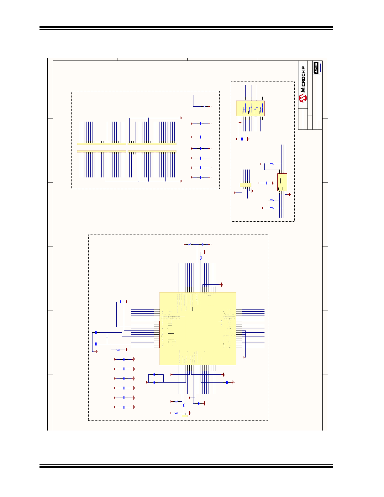
CEC1x02 Development Board User’s Guide
1
1
2
2
3
3
4
4
5
5
6
6
2 of 2
CEC1702 PIM ADAPTOR BOARD
21-Nov-17 11:47:56 PM
10758-R1.0.SchDoc
Project Title
Sch #: Date:
File:
Revision: Sheet
Designed with
Drawn By:
D. Rydahl
Sheet Title
PIM Module
Engineer:
T. Tse
03-10758
1.0
Size
C
10758
PartNumber:
Altium.com
VFLT_PLL
GPIO171
VCC_RST
VREF_ADC
JTAG_RST
VBAT_CHIP
VTR_PLL
SHD_SCK
SHD_SIO0
SHD_SIO3
VCC_RST
SHD_SIO1
SHD_CS0
SHD_SIO2
JTAG_TDI
JTAG_TDO
JTAG_TCK
JTAG_TMS
SHD_CS0
GND
GPIO156
VCC_3.3V
VCI_OUT
ADC2
PWM1
JTAG_RST
JTAG_TCK
JTAG_TDI
JTAG_TDO
SPI0_MOSI
JTAG_TMS
SPI0_MISO
SPI0_SCK
PWM4
QSPI1_CS
BGPO0
ADC1
ADC0
VCC_3.3V
GPIO163
GPIO157
ADC4
GPIO047/LCD_RESET
SHD_SIO1
KSI0
VCC_3.3V
PWM0
KSI2
VCC_RST
VCC_3.3V
KSI3
INT1
GPIO165
SPI0_CS
ADC3
GND
GPIO051
GPIO050
GND
VCC_3.3V
GPIO127
GPIO225
UART_RX
UART_TX GPIO170
GPIO171
QSPI1_MOSI
QSPI1_SCK
QSPI1_MISO
I2C3_SDA
I2C3_CLK
KSO00
KSO01
KSO02
KSO04
VCC_3.3V
GND
GPIO135
INT0
GPIO027
GPIO120
GPIO140
PWM10
GND
I2C02_SCL
I2C02_SDA/LCD_CS
PWM5
GPIO032
GPIO013
GPIO012
GPIO113
VREF_ADC
SHD_CS0
SHD_SCK
GPIO031
SHD_SIO0
SHD_SIO2
SHD_SIO3
GND
GPIO162
KSI1
VREF_ADC
VBAT_CHIP
VCC_3.3V
VCC_3.3V
VCC_3.3V
VCC_3.3V
VCC_3.3V
VCC_3.3V VCC_3.3V VCC_3.3V VCC_3.3V VCC_3.3V VCC_3.3V
NOTE:
VFLT_PLL is not connected to GND
CEC1702 CONTROLLER
SPI FLASH
MIKRO PROG HEADER
ADAPTER INTERFACE
PIN 2 PIN 16 PIN 30 PIN 37 PIN 46 PIN 62
123456789
10
J2
10k
0402
5%
R4
10k
0402
5%
R5
10k
0402
5%
R7
0.1uF
16V
0402
C5
0.1uF
16V
0402
C21
0.1uF
16V
0402
C22
0.1uF
16V
0402
C23
0.1uF
16V
0402
C6
0.1uF
16V
0402
C18
0.1uF
16V
0402
C20
0.1uF
16V
0402
C1
VCC_3.3V
0.1uF
16V
0402
C13
VCC_3.3V
0.1uF
16V
0402
C14
VCC_3.3V
0.1uF
16V
0402
C19
VCC_3.3V
0.1uF
16V
0402
C17
VCC_3.3V
0.1uF
16V
0402
C16
VCC_3.3V
0.1uF
16V
0402
C12
GPIO140 KSO01
KSI1
QSPI1_MOSI
GPIO027
SHD_SIO2
KSI3
GPIO135
GPIO225
GPIO127
GPIO157
GPIO156
UART_TX
UART_RX
GPIO170
INT0
SHD_SIO0
SPI0_SCK
SPI0_MISO
I2C02_SCL
I2C3_CLK
SPI0_CS
I2C02_SDA/LCD_CS
I2C3_SDA
SPI0_MOSI
GPIO013
GPIO012
KSO04
KSI2
GPIO120
ADC0
ADC2
ADC3
ADC1
ADC4
GND
0.1uF
16V
0402
C8
GND
1k
0402
5%
R9
GND
10k
0402
5%
R1
112
T1
VCC_3.3V
100R
0402
1%
R6
VCC_3.3VVCC_3.3V VCC_3.3V
1uF
16V
0603
C11
GND
GND
1uF
16V
0603
C15
GND
0.1uF
16V
0402
C9
22uF
6.3V
0805
C10
VCC_3.3V
GND
VCC_3.3V
PWM10
INT1
GPIO113
JTAG_TCK
JTAG_TDI
JTAG_TDO
JTAG_TMS
PWM4
GPIO050
PWM0
PWM5
SHD_SCK
PWM1
GPIO051
SHD_CS0
QSPI1_MISO
KSO02
VCI_OUT
BGPO0
GPIO163
GPIO162
GPIO031
KSO00
SHD_SIO3
KSI0
GPIO032
SHD_SIO1
QSPI1_SCK
QSPI1_CS
GPIO047/LCD_RESET
XTAL1
XTAL2
32 KHz Clock
DNP
50V
0402
C3
DNP
50V
0402
C4
DNP
Y1
GND
CE1SO/SIO12WP/SIO23VSS
4
SI/SIO0
5
SCK
6
HOLD/SIO3
7
VDD
8
SST26VF016B
U1
GPIO165
BGPO0B1GPIO145/SDA9/JTAGTDI
C2
VTR_PLLC1RESETD2VFLT_PLLD1GPIO051/TACH1E2VTR_REGE1VSS1E4VREF_ADCE3VTR_ANALOGF4GPIO050/TACH0F3GPIO034/SCK0/ID1G4VR_CAPF1GPIO200/ADC00F2GPIO203/ADC03G1GPIO201/ADC01G2GPIO202/ADC02H1GPIO202/ADC02H2VSS_ADCJ1GPIO013/SCL7/TOUT2
J2
GPIO012/SDA7/TOUT3
K1
GPIO016/Q0IO3/ICT3
K2
GPIO020/KSI1
J3
GPIO224/Q0IO1
K3
GPIO021/KSI2
J4
GPIO227/Q0IO2
K4
GPIO002/PWM5
J5
GPIO223/Q0IO0
K5
VTR2
G5
GPIO032/KSI7
H5
VTR1
G6
GPIO140/ICT5
H6
GPIO030/TIN3/KSI5
G7
GPIO056/PWM3/Q0CLK
K6
GPIO001/PWM4
J6
GPIO055/PWM2/Q0CS
K7
GPIO017/KSIO
J7
GPIO040/KSO00
K8
GPIO031/KSI6
J8
GPIO026/TIN1/KSI3
K9
GPIO054/PWM1
J9
GPIO053/PWM0
K10
KSI4/TIN2/GPIO027
J10
KSO04/GPIO107
H9
KSO07/GPIO120
H10
KSO05/GPIO112
G9
KSO06/GPIO113
G10
TX1/TFCLK/GPIO170
F9
ID2/MISO0/GPIO036
F10
VSS2
F7
JTAGSTRP/RX1/GPIO171
F8
CTS1/GPIO135
E7
JTAGRST
E8
LED0/GPIO156
D7
RTS1/PWM10/GPIO134
E10
RX0/GPIO105
E9
KSO08/Q1IO0/GPIO121
D10
TX0/GPIO104
D9
KSO11/Q1CS/GPIO124
C10
KSO02/GPIO046
C9
KSO09/Q1IO1/GPIO122
B10
LED1/GPIO157
B9
KSO12/Q1CLK1/GPIO125
A10
SDA2/GPIO154
A9
KSO03/GPIO047
B8
SCL3/GPIO010
A8
SCL2/GPIO155
B7
JTAGCLK/SDA8/GPIO147
A7
JTAGTDO/SCL9/GPIO146
B6
CTOUT0/32KHZ/GPIO165
A6
RTS0/G PIO 225
D6
CTS0/GPIO127
C6
VBAT
D5
KSO01/GPIO45
C5
VSS_ANALOG
D4
VCI_IN1/GPIO162
A5
SDA3/GPIO007
B5
XTAL1
A4
VCI_IN0/GPIO163
B4
CS0/SDA0/GPIO003
A3
JTAGTMS/SCL8/GPIO150
B3
XTAL2
A2
MOSI0/SCL0/GPIO004
B2
VCI_OUT
A1
G
O0
O
/S
/J
I
S
T
O
/
1
_
G
_A
C
_
O
/
0
/
/
_CA
O
C
0
O
/
C
3
O
/
C
O
/
C
2
O
C
2
C
/
/T
2
/
/T
G
P
I
O
016
/
Q
0
I
O
3
/
ICT
3
G
I
O
020
/
KSI
1
G
I
O
224
/
Q
0
I
O
1
G
I
O
021
/
KSI
2
G
I
O
2
2
7
/
Q
0
I
O2G
I
O
002
/
PWM
5
G
I
O
223
/
Q
0
I
O
0
VTR
2
G
I
O
032
/
KSI
7
VTR
1
G
I
O
140
/
I
C
5
G
I
O
030
/
TIN
3
/
KSI
5GP
I
O
056
/
PWM
3
/
Q0C
L
K
G
I
O
001
/
PWM
4
G
I
O
0
5
5/PWM
2
/
Q0C
S
G
P
I
O
0
1
7/KSI
O
G
I
O
040
/
K
S
O
0
0
G
I
O
031
/
KSI
6
G
P
I
O
026
/
TIN
1
/
KSI
3
G
I
O
054
/
PWM
1
G
I
O
053
/
PWM
0
/
/
/
7
/
SO
G
O
2
SO
/G
O
/
C
/G
O
/
SO
/G
O
/
/G
O
/G
O
5
/Q
/
1
/G
O
/
4
6
/Q
/
2
/G
O
/Q
/
SDA
2
/
G
P
I
O
154
S
O
0
3
/
G
P
I
O
0
4
7
S
C
L
3
/
G
P
I
O
010
S
C
2
/
G
P
I
O
1
55J
TAT
T
G
C
L
K/K
KSD
A
8
/
G
P
I
O
1
4
J
TAT
TGT
D
O/S
C
L
9
/
G
P
I
O
146
CTO
U
T
0/3
2
K
H
/
G
P
I
O
1
6
5RT
R
R
S
0
/
G
P
I
O
2
2
5
CTS
0
/
G
P
I
O
1
2
7
V
A
TAA
S
O
0
1
/
G
P
I
O
4
5
V
SSA
N
AAAL
O
G
VCIIN
1
/
G
P
I
O
162
SDA
3
/
G
P
I
O
0
0
7
TATTL
1
VCIIN
0
/
G
P
I
O
163
C
S
0
/
SDA
0
/
G
P
I
O
003
J
TAT
T
G
M
S/S
C
8
/
G
P
I
O
150
TATTL2M
O
S
I
0
/
S
C
0
/
G
P
I
O
004
VCIOU
T
CEC1702U2cec1702 wfbga-84
1OE11A
2
1Y
3
2OE42A
5
2Y
6
GND
7
3Y84Y
11
4A124OE
13
VCC
14
3OE103A
9
SN74LVC125A
U3
VCC_RST
JTAG_TMS SHD_SIO0
VCC_RST
JTAG_TCK SHD_SCK
VCC_RST
VCC_RST
SHD_SIO1 JTAG_TDO
VCC_3.3V
0.1uF
16V
0402
C2
GND
GND
GND GND GND GND GND GND
GND
GND GND GND GND GND
GND
GND
GND
GND GND
GND
GND
1234567 8 9 10 11 12 13 14 15 16 17 18 19 20 21 22 23 24 25
J1A
1234567 8 9 10 11 12 13 14 15 16 17 18 19 20 21 22 23 24 25
J1B
1234567 8 9 10 11 12 13 14 15 16 17 18 19 20 21 22 23 24 25
J1C
1234567 8 9 10 11 12 13 14 15 16 17 18 19 20 21 22 23 24 25
J1D
0R
0603
R3
GND
100k
0402
5%
R8
1uF
16V
0603
C7
0R
0603
R2
8.2 CEC1702PIM
DS50002727A-page 20 2018 Microchip Technology Inc.
7
B
X
X
157
PI
GPIO125
GPIO12
ED1
1IO1
SO02/GPIO04
1CLK1
K
KSO09
KSO12
L
Z
K
T
L
L
TD
T
DA9
145
E
P
PI
B
RE
GPIO12
1CS
1
104
PI
GPIO12
TX0
1IO0
KSO08
H
T
RE
051
TR
PI
156
10
PI
PI
ED0
RX0
D
ANALOG
1
TR
REF
11
1
170
036
PI
PI
PI
PI
GPIO10
GPIO120
0
05/
06
LK
SO04
SO07
K
K
MI
TF
ID2
TX1
UT
0
0
01
0
0
AD
AD
AD
SCL7
P
D
200/AD
203
201
202
202/AD
PI
PI
PI
PI
PI
R
PIO013
GPIO027
TIN2
SI4
UT3
SDA7
PIO012
P
P
P
P
P
P
P
P
T
P
P
P
P
P
P
P
GPIO135
TS1
ID1
H
SCK0
T
050
PIO034
PI
Page 21

Chapter 9. Bill of Materials
9.1 CEC1X02 DEVELOPMENT BOARD
CEC1x02 Development Board
User’s Guide
Reference Description Manufacturer
BATTERY MATING BATTERY LITHIUM 3 V COIN 12.5 mmPanasonic CR1220
BT1 HOLDER BATTERY COIN 12 mm DIA
THM
C1,C3,C13,C17,C21 CAP CER 0.1 µF 10 V X5R 0402 Murata GRM155R71C104KA88D
C2 CAP CER 10000 pF 50 V 10% X7R
SMD 0402
C4,C5,C6,C7,C8,
C9,C10,C11,C12,C15,
C20,C25,C26,C27,C29
C14,C18,C19,C22,C23,
C24, C31
C16,C28 CAP CER 2.2 µF 10 V 10% X5R SMD
C30 CAP CER 0.47 µF 6.3 V 10% X5R
CN1 CON USB2.0 MICRO-B FEMALE
D1 DIODE SCHOTTKY 20 V 500 mA
D2 LED RGB DIFFUSED 6SMD Cree Inc CLX6A-FKB-CJNN-
D3 Diode Schottky 30 V 0.2 A 3-Pin
DA1 IC REG LIN 3.3 V 300 mA SOT223-3 MICROCHIP MCP1755S-3302E/DB
DA2 IC REG BUCK ADJ 1A SYNC 8MSOP MICROCHIP MCP16312-E/MS
FP1 FERRITE BEAD 600 OHM 1206 1LN TDK MPZ2012S601AT000
J1 CON HDR-2.54 Male 1x8 Gold 5.84
J2 CON HDR-2.54 Male 2x10 Gold
J3 CON HDR-2.54 Male 1x6 Gold 5.84
J4 CON FFC/FPC ER-CON30HB-1 0.5
J5 CON HDR-2.54 Male 2x3 Gold 5.84
J6,J7,J8,J9 CON HDR-2.54 Male 1x16 Gold 5.84
J10,J11 CON HDR-2.54 Male 1x5 Gold 5.84
CAP CER 1 µF 25 V 10% X7R SMD
0603
CAP CER 10 µF 25 V 10% X5R SMD
0805
0402
SMD 0402
SMD R/A
SOD123
SOT-23 T/R
mH TH
Shroud 6.35 mH TH VERT
mH TH VERT
mm 30P Female SMD R/A
mH TH VERT
mH TH VERT
mH TH VERT
MPD BK-885-TR
Murata GRM155R71E103KA01D
TDK CGA3E1X7R1E105K080
Murata GRM21BR61E106KA73L
Murata GRM155R61A225KE95D
Murata GRM155R60J474KE19D
FCI 10104110-0001LF
Fairchild MBR0520L
Fairchild BAT54C
FCI 68001-108HLF
Samtec TST-110-01-G-D
FCI 68001-106HLF
EastRising ER-CON30HB-1
Samtec TSW-103-07-S-D
Samtec TSW-116-07-G-S
Samtec TSW-105-07-S-S
Manufacturer Part
Number
AC
RFJBB7A363
2018 Microchip Technology Inc. DS50002727A-page 21
Page 22

CEC1x02 Development Board User’s Guide
Reference Description Manufacturer
J12 CON HDR-2 Male 1x2 SHROUDED
LOCK SMD RA
J13 CON HDR-2.54 Female 1x6 Gold TH
R/A
JP1,JP2 CON HDR-2.54 Male 1x3 Tin 5.84 mH
TH VERT
JP3,JP5,JP6 MECH HW JUMPER 2.54 mm 1x2
Handle Gold
L1 INDUCTOR 22UH 1.65 A 96 MOHM
SMD 7.3X7.3X4.5
LCD1 DISPLAY LCD MODULE COG
GRAPHIC 128x64 DISPLAY
LD1, LD2, LD5 DIO LED YELLOW 1.8 V 30 mA
70mcd Clear SMD 0805
LD3 DIO LED RED ORANGE 2 V 10 mA
2mcd Clear SMD 0805
LD4 DIO LED GREEN 2 V 30 mA 35mcd
Clear SMD 0805
MIKROBUS1, MIKROBUS2
P1A,P1B,P1C,P1D CON HDR-1.27 Male 1x25 Gold 5.84
Q1 TRANS BJT NPN MMBT2222A 40 V 1
R1,R2 RES TKF 100R 1% 1/10 W SMD 0402 Panasonic ERJ-2RKF1000X
R3,R4,R5,R7,R8,
R10,R11,R12,R21
R14 RES TKF 2.2 k 5% 1/16 W SMD 0402 Vishay Dale CRCW04022K20JNED
R15 RES TKF 4.7 k 5% 1/10 W SMD 0402 Panasonic ERJ-2GEJ472X
R18,R20 RES TKF 2.2 k 5% 1/10 W SMD 0402 Panasonic ERJ-2GEJ222X
R19 RES TKF 1M 1% 1/10 W SMD 0402 Panasonic ERJ-2RKF1004X
R22,R26,R28,R29,R30 RES TKF 10 k 5% 1/16 W SMD 0402 Vishay CRCW040210K0JNED
R23 RES TKF 47 k 5% 1/10 W SMD 0402 Panasonic ERJ-2GEJ473X
R24 RES TKF 8.2 k 5% 1/10 W SMD 0402 Panasonic ERJ-2GEJ822X
R25,R27 RES TKF 10 k 5% 1/10 W SMD 0402 Panasonic ERJ-2GEJ103X
R31 RES TKF 10 k 5% 1/16 W SMD 0402 Vishay CRCW040210K0JNED
R32 RES TKF 0R 1/10 W SMD 0603 Panasonic ERJ-3GSY0R00V
R34 RES TKF 220 k 5% 1/10 W SMD 0402 Panasonic ERJ-2GEJ224X
R35 RES TKF 100 k 5% 1/10 W SMD 0402 Panasonic ERJ-2GEJ104X
R36 RES TKF 330 k 5% 1/10 W SMD 0402 Panasonic ERJ-2GEJ334X
R37,R41,R46 RES TKF 1 k 5% 1/16 W SMD 0402 Panasonic ERJ-2GEJ102X
R38,R39,R40 RES TKF 330R 5% 1/10 W SMD 0402 Panasonic ERJ-2GEJ331X
R42 RES TKF 68 k 5% 1/10 W SMD 0402 Panasonic ERJ-2GEJ683X
R43 RES TKF 13 k 5% 1/10 W SMD 0402 Panasonic ERJ-2GEJ133X
R44 RES TKF 470R 5% 1/16 W SMD 0402 Yageo RC0402JR-07470RL
R45 RES TKF 130 k 5% 1/10 W SMD 0402 Panasonic ERJ-2GEJ134X
R6,R9,R13,R16,R17 RES TKF 3.3 k 5% 1/10 W SMD 0402 Panasonic ERJ-2GEJ332X
RP1 Res Variable 10 k 20% TH P090S TT ELECTRONICS/BI P090S-04F20BR10K
mikroBUS HOST Sullins Connector
mH TH VERT
A 350 mW SOT-23
RES TKF 100 k 1% 1/10 W SMD 0402 Panasonic ERJ-2RKF1003X
EastRising ER-CON2.0-2P-SMD
Sullins PPPC061LGBN-RC
Samtec TSW-103-07-T-S
TE Connectivity 881545-2
Bourns Inc. SRR0745A-220M
EastRising ERC12864FS-1
Lite On Inc. LTST-C170KSKT
Lite On Inc. LTST-C170EKT
Lite On Inc. LTST-C170KGKT
Solutions
Samtec TMS-125-01-G-S
Fairchild MMBT2222A
Manufacturer Part
Number
PPTC081LFBN-RC
DS50002727A-page 22 2018 Microchip Technology Inc.
Page 23

Bill of Materials
Reference Description Manufacturer
T1,T2,T3,T4,T5,T6 SWITCH TACT SPST 12 V 50 mA
PTS645SM43SMTR92 LFS SMD
U1 MCHP INTERFACE USB I2C/UART
MCP2221A-I/ML QFN-16
U5 IC REG LDO ADJ 0.15 A SC70-5 MICROCHIP MIC5377YC5-TR
X1 CON HDR-2.54 Female 2x5 GOLD TH
R/A
X2,X3,X5,X6,X7, X8,X9 CON HDR-2.54 Male 1x2 Tin 6.75 mH
TH VERT
X4 CON POWER 2 mm 5.5 mm SWITCH
TH R/A
Wurth Electronics Inc 430182043816
MICROCHIP MCP2221A-I/ML
Samtec SSQ-105-02-G-D-RA
Molex 0901200122
CUI Inc. PJ-002AH
Manufacturer Part
Number
9.2 CEC1702PIM DEVELOPMENT BOARD
Reference Description Manufacturer Manufacturer Part Number
C1,C2,C5,C6,C8,
C9,C12,C13,C14,C1
6,
C17,C18,C19,C20,C
21, C22,C23
C10 CAP CER 22 µF 6.3 V 20% X5R SMD
C7,C11,C15 CAP CER 1 µF 16 V 10% X5R SMD 0603 AVX 0603YD105KAT2A
J1A,J1B,J1C,J1D CON HDR-1.27 Female 1x25 TH VERT Preci-Dip 851-87-025-10-001101
J2 CON HDR-2.54 Male 2x5 0.100" (2.54
R1,R4,R5,R7 RES TKF 10 k 5% 1/10 W SMD 0402 Panasonic ERJ-2GEJ103X
R2,R3 RES TKF 0R 1/10 W SMD 0603 Panasonic ERJ-3GSY0R00V
R6 RES TKF 100R 1% 1/10 W SMD 0402 Panasonic ERJ-2RKF1000X
R8 RES TKF 100 k 5% 1/10 W SMD 0402 Panasonic ERJ-2GEJ104X
R9 RES TKF 1 k 5% 1/16 W SMD 0402 Panasonic ERJ-2GEJ102X
T1 CON HDR-2.54 Male 1x2 Tin 6.75 mH TH
U1 MCHP MEMORY SERIAL FLASH 16M
U2 CRYPTO EMBEDDED CONTROLLER
U3 IC LOGIC SN74LVC125ADBR Quad Bus
Y1 (DNP) CRYSTAL 32.768 kHz 12.5 pF SMD
C3,C4 (DNP) CAP CER 10 pF 50 V 5% NP0 SMD 0402 Murata GRM1555C1H100JZ01D
CAP CER 0.1 µF 16 V 10% X7R SMD
0402
0805
mm) TH VERT
VERT
104 MHz SST26VF016B-104I/SM SOIJ-8
480 K
CEC1702Q-C2-I/SX
Buffer Gate SSOP-14
ABS07
Murata GRM155R71C104KA88D
Murata GRM21BR60J226ME39L
Samtec TSW-105-07-G-D
Molex 0901200122
MICROCHIP SST26VF016B-104I/SM
MICROCHIP SST26VF016B-104I/SM
TI CEC1702Q-C2-I/SX
Seiko SC32S-12.5PF20PPM
2018 Microchip Technology Inc. DS50002727A-page 23
Page 24

Worldwide Sales and Service
AMERICAS
Corporate Office
2355 West Chandler Blvd.
Chandler, AZ 85224-6199
Tel: 480-792-7200
Fax: 480-792-7277
Technical Support:
http://www.microchip.com/
support
Web Address:
www.microchip.com
Atlanta
Duluth, GA
Tel: 678-957-9614
Fax: 678-957-1455
Austin, TX
Tel: 512-257-3370
Boston
Westborough, MA
Tel: 774-760-0087
Fax: 774-760-0088
Chicago
Itasca, IL
Tel: 630-285-0071
Fax: 630-285-0075
Dallas
Addison, TX
Tel: 972-818-7423
Fax: 972-818-2924
Detroit
Novi, MI
Tel: 248-848-4000
Houston, TX
Tel: 281-894-5983
Indianapolis
Noblesville, IN
Tel: 317-773-8323
Fax: 317-773-5453
Tel: 317-536-2380
Los Angeles
Mission Viejo, CA
Tel: 949-462-9523
Fax: 949-462-9608
Tel: 951-273-7800
Raleigh, NC
Tel: 919-844-7510
New York, NY
Tel: 631-435-6000
San Jose, CA
Tel: 408-735-9110
Tel: 408-436-4270
Canada - Toronto
Tel: 905-695-1980
Fax: 905-695-2078
ASIA/PACIFIC
Australia - Sydney
Tel: 61-2-9868-6733
China - Beijing
Tel: 86-10-8569-7000
China - Chengdu
Tel: 86-28-8665-5511
China - Chongqing
Tel: 86-23-8980-9588
China - Dongguan
Tel: 86-769-8702-9880
China - Guangzhou
Tel: 86-20-8755-8029
China - Hangzhou
Tel: 86-571-8792-8115
China - Hong Kong SAR
Tel: 852-2943-5100
China - Nanjing
Tel: 86-25-8473-2460
China - Qingdao
Tel: 86-532-8502-7355
China - Shanghai
Tel: 86-21-3326-8000
China - Shenyang
Tel: 86-24-2334-2829
China - Shenzhen
Tel: 86-755-8864-2200
China - Suzhou
Tel: 86-186-6233-1526
China - Wuhan
Tel: 86-27-5980-5300
China - Xian
Tel: 86-29-8833-7252
China - Xiamen
Tel: 86-592-2388138
China - Zhuhai
Tel: 86-756-3210040
ASIA/PACIFIC
India - Bangalore
Tel: 91-80-3090-4444
India - New Delhi
Tel: 91-11-4160-8631
India - Pune
Tel: 91-20-4121-0141
Japan - Osaka
Tel: 81-6-6152-7160
Japan - Tokyo
Tel: 81-3-6880- 3770
Korea - Daegu
Tel: 82-53-744-4301
Korea - Seoul
Tel: 82-2-554-7200
Malaysia - Kuala Lumpur
Tel: 60-3-7651-7906
Malaysia - Penang
Tel: 60-4-227-8870
Philippines - Manila
Tel: 63-2-634-9065
Singapore
Tel: 65-6334-8870
Taiwan - Hsin Chu
Tel: 886-3-577-8366
Taiwan - Kaohsiung
Tel: 886-7-213-7830
Taiwan - Taipei
Tel: 886-2-2508-8600
Thailand - Bangkok
Tel: 66-2-694-1351
Vietnam - Ho Chi Minh
Tel: 84-28-5448-2100
EUROPE
Austria - Wels
Tel: 43-7242-2244-39
Fax: 43-7242-2244-393
Denmark - Copenhagen
Tel: 45-4450-2828
Fax: 45-4485-2829
Finland - Espoo
Tel: 358-9-4520-820
France - Paris
Tel: 33-1-69-53-63-20
Fax: 33-1-69-30-90-79
Germany - Garching
Tel: 49-8931-9700
Germany - Haan
Tel: 49-2129-3766400
Germany - Heilbronn
Tel: 49-7131-67-3636
Germany - Karlsruhe
Tel: 49-721-625370
Germany - Munich
Tel: 49-89-627-144-0
Fax: 49-89-627-144-44
Germany - Rosenheim
Tel: 49-8031-354-560
Israel - Ra’anana
Tel: 972-9-744-7705
Italy - Milan
Tel: 39-0331-742611
Fax: 39-0331-466781
Italy - Padova
Tel: 39-049-7625286
Netherlands - Drunen
Tel: 31-416-690399
Fax: 31-416-690340
Norway - Trondheim
Tel: 47-7289-7561
Poland - Warsaw
Tel: 48-22-3325737
Romania - Bucharest
Tel: 40-21-407-87-50
Spain - Madrid
Tel: 34-91-708-08-90
Fax: 34-91-708-08-91
Sweden - Gothenberg
Tel: 46-31-704-60-40
Sweden - Stockholm
Tel: 46-8-5090-4654
UK - Wokingham
Tel: 44-118-921-5800
Fax: 44-118-921-5820
DS50002727A-page 24 2018 Microchip Technology Inc.
10/25/17
Page 25

Mouser Electronics
Authorized Distributor
Click to View Pricing, Inventory, Delivery & Lifecycle Information:
Microchip:
DM990013 DM990013-BNDL
 Loading...