

Page 1

BM83 EVB
BM83 Bluetooth® Audio Development Board User's Guide
Introduction
The BM83 Bluetooth Audio Development Board (BM83 EVB) enables the user to evaluate and demonstrate the
functionality of the BM83 audio module and IS2083BM System-on-Chip (SoC). This board is a complete, all-in-one
solution to develop multiple Bluetooth audio applications including portable speakers and headphones. The BM83
EVB features an on-board PIC32 for Host MCU mode applications, an external codec to improve audio quality, a
digital microphone to capture voice audio, indicator LEDs and buttons for ease of development.
In addition to the BM83 EVB, the IS2083 SDK and IS208x_Config_GUI_Tool (Config Tool) are provided to customize
the audio processing settings.
Features
• BM83 module, qualified for Bluetooth 5.0 specifications
• On-board microcontroller (PIC32MX450F256L) for easy operation and feature demonstration
• Plug-in module (PIM) socket for external microcontroller (MCU)
• STMicroelectronics codec (STA369BW) Daughter Board
• Digital Microphone (Knowles’ SPH0641LU4H-1) Daughter Board
• J-Link 6-Pin Adapter Board for IS2083BM debugging
• On-board keypad matrix (audio control buttons) that can be controlled either by the BM83 module or the onboard PIC32 MCU, which makes it easy for playback control
• Aux-in, MIC-In, and Stereo out ports
• On-board thermistor
• 2 LEDs for the Bluetooth subsystem and various other LEDs configurable by the on-board MCU
• JTAG program/debug port, USB to UART port, XPRO header interfaces
• Li-ion battery connector, 15V DC power jack and USB power source
© 2019 Microchip Technology Inc.
User Guide
DS50002902A-page 1
Page 2

BM83 EVB
Table of Contents
Introduction.....................................................................................................................................................1
Features......................................................................................................................................................... 1
1. Quick References....................................................................................................................................4
1.1. Reference Documentation............................................................................................................4
1.2. Hardware Requirements.............................................................................................................. 4
1.3. Software Requirements................................................................................................................4
1.4. Acronyms/Abbreviations...............................................................................................................5
2. Kit Overview............................................................................................................................................ 8
2.1. Kit Contents..................................................................................................................................8
3. Hardware...............................................................................................................................................10
3.1. Hardware Features.....................................................................................................................11
3.1.1. Power Supply...............................................................................................................11
3.1.2. USB Connectivity.........................................................................................................12
3.1.3. Switches and Push Buttons.........................................................................................12
3.1.4. LEDs............................................................................................................................12
3.1.5. Headers....................................................................................................................... 13
3.1.5.1. I2S Header................................................................................................ 13
3.1.5.2. Audio Daughter Board Interface Header................................................... 13
3.1.5.3. Audio Control Button Headers...................................................................14
3.1.5.4. BM83 Carrier Board Interface................................................................... 15
3.1.5.5. ICSP Header............................................................................................. 16
3.1.5.6. Xplained PRO Header...............................................................................16
3.1.5.7. Digital Microphone Headers...................................................................... 17
4. Embedded Mode Quick Demo.............................................................................................................. 18
5. Firmware Update...................................................................................................................................20
5.1. Firmware Update over UART..................................................................................................... 20
5.2. Firmware Update over USB ...................................................................................................... 23
6. Customizing Module Parameters.......................................................................................................... 28
6.1. Config Tool Setup.......................................................................................................................28
7. Appendix A: BM83 EVB Reference Schematics................................................................................... 41
8. Appendix B: STA369BW Audio Daughter Board...................................................................................55
9. Appendix C: Digital Microphone Daughter Board................................................................................. 57
10. Appendix D: J-Link 6-Pin Adapter Board.............................................................................................. 58
11. Appendix E: Updating PIC32 MCU Parameters....................................................................................59
12. Appendix F: Hardware Setup for Application Demo in Host MCU Mode.............................................. 63
12.1. Host MCU Mode Quick Demo.................................................................................................... 64
© 2019 Microchip Technology Inc.
User Guide
DS50002902A-page 2
Page 3

BM83 EVB
13. Appendix G: Hardware Setup for Application Demo in Embedded Mode.............................................67
14. Appendix H: Bluetooth Audio Demonstration in Embedded Mode with Internal Codec........................69
15. Document Revision History...................................................................................................................70
The Microchip Website.................................................................................................................................71
Product Change Notification Service............................................................................................................71
Customer Support........................................................................................................................................ 71
Microchip Devices Code Protection Feature................................................................................................ 71
Legal Notice................................................................................................................................................. 71
Trademarks.................................................................................................................................................. 72
Quality Management System....................................................................................................................... 72
Worldwide Sales and Service.......................................................................................................................73
© 2019 Microchip Technology Inc.
User Guide
DS50002902A-page 3
Page 4

1. Quick References
1.1 Reference Documentation
For further study, refer to the following:
• BM83 Bluetooth® Stereo Audio Module Data Sheet
• IS2083 Bluetooth® Stereo Audio SoC Data Sheet
• IS2083 SDK User’s Guide (DS50002894)
• BM83 Host MCU Firmware Development Guide
• IS2083 Bluetooth® Audio Application Design Guide
• IS2083 SDK Debugger User’s Guide
• IS2083 Reference Design Application Note
Note: For a complete list of development support tools and documentation, visit http://www.microchip.com/BM83.
1.2 Hardware Requirements
• BM83 Bluetooth® Audio Development Board (BM83 EVB)
• BM83 module mounted on BM83 Carrier Board
• Bluetooth-enabled smartphone:
– Android™ device running on Android 4.3 or later version
– iOS: iPhone® 4S or later version
• Windows® host PC with USB port
• Speaker, microphone or headset
• Type-A to Micro-B USB cable
• STA369BW Audio Daughter Board
• Digital Microphone Daughter Board
• 15V DC power adapter
• MPLAB® REAL ICE™/MPLAB ICD 3/PICkit™ 3
• J-Link 6-Pin Adapter Board
BM83 EVB
Quick References
1.3 Software Requirements
Note: For the following software tools and firmware files, refer to http://www.microchip.com/BM83.
• IS2083 firmware
• Host MCU firmware
• isUpdate tool
• Config GUI tool
• MPLAB Integrated Development Environment (MPLAB X IDE) tool
• Microchip Bluetooth Audio Application for smartphone
Note: MPLAB X IDE is available for download from Microchip website at: http://www.microchip.com/mplab/mplab-x-
ide.
© 2019 Microchip Technology Inc.
User Guide
DS50002902A-page 4
Page 5

1.4 Acronyms/Abbreviations
Table 1-1. Acronyms/Abbreviations
Acronyms/Abbreviations Description
A2DP Advanced Audio Distribution Profile
AAC Advanced Audio Codec
ADC Analog-to-Digital Converter
AEC Acoustic Echo Cancellation
AFH Adaptive Frequency Hopping
ANCS Apple Notification Center Service
API Application Programming Interfaces
AVRCP Audio/Video Remote Control Profile
AW Audio Widening
BDR Basic Data Rate
BER Bit Error Rate
BLE Bluetooth Low Energy
BOM Bill of Materials
BPF Band Pass Filter
BR Basic Rate
CVSD Continuous Variable Slope Delta
DAC Digital-to-Analog Converter
DFU Device Firmware Upgrade
DIS Device Information Service
DLE Data Length Extension
DPSK Differential Phase Shift Keying
DQPSK Differential Quadrature Phase Shift Keying
DR Receive Data
DSP Digital Signal Processor
DT Transmit Data
EDR Enhanced Data Rate
EMC Electromagnetic Compatibility
EVB Evaluation Board
FET Field Effect Transistor
GAP General Access Profile
GATT General Attribute Profile
GFSK Gaussian Frequency Shift Keying
GPIO General Purpose Input Output
GUI Graphical User Interface
HFP Hands-free Profile
HPF High Pass Filter
HSP Headset Profile
BM83 EVB
Quick References
© 2019 Microchip Technology Inc.
User Guide
DS50002902A-page 5
Page 6

...........continued
Acronyms/Abbreviations Description
HW Hardware
I2C/I2C Inter-Integrated Circuit
I2S/I2S Inter-IC Sound
IC Integrated Circuit
ICSP In-Circuit Serial Programming
IDE Integrated Development Environment
IF Intermediate Frequency
IPE Integrated Programming Environment
JTAG Joint Test Action Group
LDO Low-Dropout
LED Light Emitting Diode
LNA Low-Noise Amplifier
LPA Linear Power Amplifier
LSB Least Significant Bit
MAC Medium Access Control
MB DRC Multiband Dynamic Range Compression
MCLK Master Clock
MCU Microcontroller
MEMS Micro-Electro-Mechanical Systems
MFB Multi-function Button
Modem Modulator-demodulator
MPA Medium Power Amplifier
mSBC Modified Sub-band Coding
MSPK Multi-speaker
NR Noise Reduction
OTA Over-the-Air
PBAP Phone Book Access Profile
PCB Printed Circuit Board
PCM Pulse Code Modulation
PDM Pulse Density Modulation
PIM Plug-in Module
PLC Packet Loss Concealment
PMU Power Management Unit
POR Power-on Reset
PWM Pulse Width Modulation
RF Radio Frequency
RFS Receive Frame Sync
RoHS Restriction of Hazardous Substances
RSSI Received Signal Strength Indicator
RX Receiver
BM83 EVB
Quick References
© 2019 Microchip Technology Inc.
User Guide
DS50002902A-page 6
Page 7

...........continued
Acronyms/Abbreviations Description
SAR Successive Approximation Register
SBC Sub-band Coding
SCO Synchronous Connection-oriented
SDK Software Development Kit
SIG Special Interest Group
SNR Signal-to-Noise Ratio
SoC System-on-Chip
SPP Serial Port Profile
SW Software
TX Transmitter
UART Universal Asynchronous Receiver-Transmitter
UI User Interface
USB Universal Serial Bus
VB Virtual Bass Enhancement
VCO Voltage-controlled Oscillator
WDT Watchdog Timer
BM83 EVB
Quick References
© 2019 Microchip Technology Inc.
User Guide
DS50002902A-page 7
Page 8

2. Kit Overview
Host MCU (PIC32MX450F256L)
PIM Socket (External MCU)
15V DC Adapter (P200)
USB-UART Port (J600)
Power Switch (SW200)
MFB Button (SW701)
Bluetooth Module USB (J200)
Li-ion Battery Connector (J201)
Type-A USB (P400)
ICSP Header (J400)
BM83 JTAG Header (J301)
XPRO Header (J304)
STA369BW Audio
Daughter Board
ANA MIC1(P500)
LINE_IN (P501)
I2S Header (J404, J405)
ANA MIC2 (P502)
Stereo Out (P503)
Carrier Board Interface (J300)
BM83 Carrier Board
BM83 Module
Digital Microphone
Daughter Boards
Audio Control Buttons Header
(J700, J701, J702)
This section provides an overview of the BM83 EVB. The following figure illustrates the top view of the BM83 EVB
with its components.
Figure 2-1. BM83 EVB Components
BM83 EVB
Kit Overview
2.1 Kit Contents
The BM83 EVB includes the following:
• One BM83 EVB that contains a BM83 module (BM83SM1-00AA) mounted on a BM83 Carrier Board
• One 15V DC power adapter
• One pair of speaker cables
• One Type-A to Micro-B USB cable
• One STA369BW Audio Daughter Board
• Two Digital Microphone Daughter Boards
• One J-link 6-pin Adapter Board
© 2019 Microchip Technology Inc.
User Guide
DS50002902A-page 8
Page 9

Figure 2-2. Kit Contents
BM83 EVB
STA369BW Audio
Daughter Board
Digital Microphone
Daughter Boards
Power Cable
BM83 Carrier Board
J-Link Adapter Board
Speaker Cable
Micro-B USB Cable
DC Power Adapter
BM83
Module
BM83 EVB
Kit Overview
Note: If any part of the BM83 EVB is missing, contact your Microchip sales office for assistance. A list of Microchip
offices for sales and service is provided on the back page of this document.
© 2019 Microchip Technology Inc.
User Guide
DS50002902A-page 9
Page 10

3. Hardware
SYS_PWR
LED2
AOHPR
AOHPM
AOHPL
MIC1_P
MIC2_N
MIC_BIAS
UART
BAT_IN
Buttons and
Switches
MIC and
Bias Circuit
Audio
Input
Jack
Status LEDs
Power
Jack
15V
Adapter
ADC CH
16 MHz
Crystal
SPKR
SPKL
Thermistor
Li-Ion
Battery
Audio
Output
Jack
Aux-In Jack
USB to UART
(MCP2200)
3V35V
Regulator
ADAP_IN
Micro-B
USB
12 MHz
Crystal
Power
Switch
15V5V
15V
3V3
I/O
5V
3V3
LDO
5V
P3_4
Mode
Switch
Type-A USB
Audio
Input
Jack
MIC and
Bias Circuit
DMIC_CLK
Audio Daugh ter
Board
3.3 V
15 V
5
V
I2S
15 V
LED1
CPU JTAG
JTAG
XPRO
Header
I/O
AIRAIL
DMIC
1
L
/
R
DMIC
2
L
/
R
MIC1_N
MIC2_P
BM83 Module on the
BM83 Carrier Board
External MCU
(PIC32MX450F256L)
/PIM Socket
Micro-B
USB
USB
J-link
Adapter
Board
Bluetooth Audio Development Board
Regulator
STA369BW
Digital Microphone
Daugther Boards
This chapter describes the hardware features of the BM83 EVB. The BM83 EVB includes a range of peripheral
components.
Figure 3-1. Block Diagram
BM83 EVB
Hardware
© 2019 Microchip Technology Inc.
User Guide
DS50002902A-page 10
Page 11

3.1 Hardware Features
Dxxx - LEDs
JPxxx/Jxxx - Jumpers
Sxxx/SWxxx - Switches/Push buttons
Legends:
D401
D402
D403
D404
D405
D406
D407
D411
S400
SW402
SW403
SW400
SW705
SW702
SW707
SW708
SW704
J600
D401
D402
D403
D404
D405
D406
D407
D411
S400
SW402
SW403
SW400
SW200
SW701
SW401
SW711
SW703
D202
D600
D203
D209
JP203
JP201
JP400
J200
JP600, JP601
D300, D301, D302
SW700
SW300
J700, J701, J702
J404
J405
JP501
JP503
J401, J402, J403
JP305
JP304
J505, J504
The following sections provide detailed information on the BM83 EVB components. To locate these components in
the BM83 EVB, refer to Figure 2-1 and Figure 3-2.
Figure 3-2. BM83 EVB Switches, LEDs, and Jumpers
BM83 EVB
Hardware
3.1.1 Power Supply
The BM83 EVB can be powered using any one of the following:
• Li-ion battery (J201) – when using a battery input, mount a jumper on JP200 and pin 1 and 2 of JP201. Do not
mount a jumper on JP202. JP202 is a provision for connecting a battery power source with 2.54 mm connector.
• 15V DC power adapter (P200)
• USB (J200 and J600) – USB cable is connected to the PC which provides 5V (USB_5V)
Note: Power switch (SW200) is utilized to switch between two 5V power sources available on board:
• 5V_DC: derived from 15V DC
• 5V_USB: supplied by 5V USB source
Note: To locate these power sources available on the BM83 EVB, refer to Figure 2-1.
© 2019 Microchip Technology Inc.
User Guide
DS50002902A-page 11
Page 12

3.1.2 USB Connectivity
The USB ports for BM83 EVB are:
• Micro-B USB port (J600 UART USB) – USB signals are converted to UART by the serial converter MCP2200,
which is connected to BM83 module.
• Micro-B USB port (J200 BT_USB) – USB signals are directly connected to the BM83 module.
• Type A USB port (P400- MCU_USB) – USB signals are directly connected to host MCU ( PIC32MX450F256L).
Note: To locate these USB ports available on the BM83 EVB, refer to Figure 2-1.
3.1.3 Switches and Push Buttons
The functions of the switches and push buttons on the BM83 EVB are:
• S400 – Switch to select between on-board PIC32 MCU or external Plug-in Module (PIM)
• SW200 – Power switch to switch between 5V_DC and 5V_USB
• SW300 – Mode selection switch for configuring BM83 module into Application mode or Test mode
• SW400 – Microcontroller to Bluetooth control switch
• SW401 – Reset button for the host MCU (MCU_RESET)
• SW402 – Microcontroller to Bluetooth control switch
• SW403 – Microcontroller to Bluetooth control switch
• SW700 – Reset button for BM83 module (RST_N)
• SW701 – Multifunction button (MFB)
• SW702 – Increase volume (VOL_UP)
• SW703 – Enter into pairing mode (PAIRING)
• SW704 – Play or pause the audio playback (PLAY/PAUSE)
• SW705 – Decrease volume (VOL_DN)
• SW707 – Skip the audio track forward (FWD)
• SW708 – Skip the audio track backward (REV)
• SW711 – Select button (SEL), turns on the system and puts the system into Pairing mode during Host MCU
mode application demonstration
Note: To locate these switches and push buttons available on the BM83 EVB, refer to Figure 3-2.
The following table provides the settings of mode selection switch (SW300) for configuring the BM83 module in
various operating modes.
Table 3-1. Mode Selection Switch (SW300) Details
BM83 EVB
Hardware
Mode Pin Description
Test mode SW300 is placed in ON (P3_4: Low) position
Application mode SW300 is placed in OFF (P3_4: Floating) position
3.1.4 LEDs
All the on-board LEDs are categorized into three main types:
• Power LEDs:
• LEDs driven by the BM83 module:
• Host MCU (PIC32) related LEDs:
Note: To locate these LEDs available on the BM83 EVB, refer to Figure 3-2.
© 2019 Microchip Technology Inc.
– Red (D600 and D202)
– Green (D209 and D203)
– Red (D301)
– Blue (D300)
– Green (D401-D407 )
– Green (D411)
User Guide
DS50002902A-page 12
Page 13

3.1.5 Headers
The following headers are available on the BM83 EVB.
Note: To locate these headers available on the BM83 EVB, refer to Figure 2-1.
3.1.5.1 I2S Header
I2S header (J405) provides the interface to connect an STA369BW Audio Daughter Board to the BM83 module. The
following table provides the pin details of I2S header.
Table 3-2. I2S Header (J405) Pin Details
Pin Number Pin Name
1 RFS1
2 SCLK1
3 DR1
4 DT1
5 MCLK1
6 GND
7 3V3_IO
BM83 EVB
Hardware
Note: Connect J405 and J404 to enable I2S interface with the STA369BW Audio Daughter Board.
3.1.5.2 Audio Daughter Board Interface Header
The Audio Daughter Board interface headers (J500 and J501) provide the interface to use the STA369BW Audio
Daughter Board. The Table 3-3 and Table 3-4 tables provide the pin details of these headers.
Table 3-3. Audio Daughter Board Interface Header (J500) Pin Details
Pin Number Pin Name Pin Number Pin Name
1 GND 11 I2S_DR1
2 GND 12 I2S_SCLK1
3 GPIO/RxD 13 I2S_DT1
4 GPIO/CTS# 14 I2S_MCLK1
5 GPIO/TxD 15 GND
6 GPIO/RTS# 16 GND
7 GPIO/SCL 17 15V_DC_IN
8 GPIO/RST# 18 3V3_GEN
9 GPIO/SDA 19 15V_DC_IN
10 I2S_RFS1 20 5V_DC
Table 3-4. Audio Daughter Board Interface Header (J501) Pin Details
Pin Number Pin Name Pin Number Pin Name
1 NC 7 NC
2 NC 8 GPIO/PROT_N_DSP
3 GPIO/DSP_IRQ_N 9 NC
4 GPIO/SLEEP_N_DSP 10 NC
© 2019 Microchip Technology Inc.
User Guide
DS50002902A-page 13
Page 14

...........continued
Pin Number Pin Name Pin Number Pin Name
5 NC 11 GND
6 GPIO/MUTE_N_DSP 12 GND
3.1.5.3 Audio Control Button Headers
The audio control button headers (J700, J701, J702) provide the mechanism to control the audio function buttons
either by the BM83 module (Embedded mode) or on-board PIC32 MCU (Host MCU mode). The following tables
provide the header pin description Embedded and Host MCU mode configurations.
Table 3-5. Audio Control Button Headers (J700, J701, and J702) Pin Description
Pin Number Pin Name Description
1 PLY/PAU Play or pause
2 REV Reverse
3 FWD Forward
4 VOL– Volume down
5 VOL+ Volume up
BM83 EVB
Hardware
(1)
6 PAIRING Used for pairing the module with a smartphone (only for Host
MCU mode)
7 Sel Not used
8 NC Not connected
1. To locate these headers on the BM83 EVB, refer to Figure 2-1.
Table 3-6. Embedded Mode Audio Control Button Header Configurations (J700, J701, and J702)
Pin Number Jumper Names and Positions Description
J700 J701 J702
1 Open Mount a jumper on J701 and J702 Audio streaming is controlled
2 Open Mount a jumper on J701 and J702
3 Open Mount a jumper on J701 and J702
4 Open Mount a jumper on J701 and J702
5 Open Mount a jumper on J701 and J702
6 Open Open Open
7 Open Mount a jumper on J701 and J702
8 Open Open Open
1. To locate these headers on the BM83 EVB, refer to Figure 2-1.
by the BM83 module in
Embedded mode.
(1)
© 2019 Microchip Technology Inc.
User Guide
DS50002902A-page 14
Page 15

BM83 EVB
Hardware
Table 3-7. Host MCU Mode Audio Control Button Header Configurations (J700, J701, and J702)
Pin Number Jumper Names and Positions Description
J700 J701 J702
1 Mount a jumper on J700 and J701 Open Audio streaming is controlled by on-
2 Mount a jumper on J700 and J701 Open
3 Mount a jumper on J700 and J701 Open
4 Mount a jumper on J700 and J701 Open
5 Mount a jumper on J700 and J701 Open
6 Mount a jumper on J700 and J701 Open
7 Mount a jumper on J700 and J701 Open
8 Open Open Open
1. To locate these headers on the BM83 EVB, refer to Figure 2-1.
3.1.5.4 BM83 Carrier Board Interface
The following table provides the pin details of J300 and the BM83 module interface with the BM83 EVB.
Table 3-8. Carrier Board Interface (J300) Pin Details
Pin Name Pin Number Pin Name
(1)
board PIC32MX450F256L MCU in
Host MCU mode.
BK1_O_1V5 1 2 MCLK1
LED3 3 4 DT1
NC 5 6 DR1
RST_N 7 8 SCLK1
DP 9 10 RFS1
DM 11 12 GND
GND 13 14 P3_7
GND 15 16 P3_5
P2_7 17 18 NC
P1_3 19 20 BK2_O_1V8
P1_2 21 22 NC
P0_5 23 24 P0_1
P0_2 25 26 P0_0
P0_3 27 28 P2_3
P0_6 29 30 P0_7
LED2 31 32 UART_TXD
P1_6 33 34 UART_RXD
LED1 35 36 SK2_KEY_AD
P3_4 37 38 PWM
SK1_AMB_DET 39 40 MFB
© 2019 Microchip Technology Inc.
User Guide
DS50002902A-page 15
Page 16

...........continued
Pin Name Pin Number Pin Name
NA 41 42 DMIC2_R
NA 43 44 DMIC2_L
P3_2 45 46 VDD_IO
GND 47 48 SYS_PWR
MIC_BIAS 49 50 BAT_IN
MIC_P1 51 52 ADAP_IN
MIC_N1 53 54 NC
AIL 55 56 P2_6
AIR 57 58 DMIC1_R
MIC_P2 59 60 DMIC1_L
MIC_N2 61 62 DMIC_CLK
AOHPL 63 64 GND
AOHPM 65 66 GND
BM83 EVB
Hardware
AOHPR 67 — —
3.1.5.5 ICSP Header
ICSP header (J400) provides the programming/debugging interface for the on-board PIC32 MCU
(PIC32MX450F256L). To locate this header on the BM83 EVB, refer to Figure 2-1. The following table provides the
ICSP header pin description.
Table 3-9. ICSP Header (J400) Pin Description
Pin Number Description
1 Reset (MCLR)
2 Power supply (3V3_PIC)
3 Ground (GND)
4 Data (PGED1)
5 Clock (PGEC1)
6 Not connected (NC)
3.1.5.6 Xplained PRO Header
The BM83 EVB provides 20-pin XPRO header (J304) to interface with XPRO platform. The following table provides
the pin details of XPRO header.
Table 3-10. XPRO Header (J304) Pin Details
Pin Name Pin Number Pin Name
NC
SK2_KEY_AD
NA
PWM
P0_6
© 2019 Microchip Technology Inc.
1 2
3
5
7
9
User Guide
GND
4 SK1_AMB_DET
6 NA
8 P0_0
10 P3_5
DS50002902A-page 16
Page 17

...........continued
Pin Name Pin Number Pin Name
BM83 EVB
Hardware
P1_3
UART_RXD
P0_7
P2_3
GND
3.1.5.7 Digital Microphone Headers
The 5-pin digital microphone header provides an interface to BM83 EVB and the Digital Microphone Daughter Board.
The pin description is provided in the following table.
Table 3-11. Digital Microphone Headers (J1, J503, and J502) Pin Description
Pin
Number
1 VDD VDD DIGMIC VDD DIGMIC Power supply from BM83 EVB
2 CLOCK DMIC1_CLK DMIC1_CLK Clock input to the microphone from
3 GND GND GND Ground
4 DATA DMIC1_L DMIC1_R PDM output from the microphone to
Digital
Microphone
Daughter
Board
Pin Name (J1) Pin Name (J503) Pin Name (J502)
11
13
15
17
19
12 P1_2
14 UART_TXD
16 P2_6
18 P1_6
20 3V3_IO
BM83 EVB Pin Description
BM83 module
BM83 module
5 SEL DM1 SELECT DM2 SELECT Select input for microphone
© 2019 Microchip Technology Inc.
User Guide
DS50002902A-page 17
Page 18

4. Embedded Mode Quick Demo
This section provides a quick demo to stream audio using the BM83 module in Embedded mode.
Perform the following steps:
Note: The BM83 EVB is preconfigured for the Embedded mode quick demo.
1. Unbox the kit and connect the speaker cables to the STA369BW Audio Daughter Board at CN1 and CN2, and
connect the cables to the speaker.
Figure 4-1. Speakers Connected to the STA369BW Audio Daughter Board
BM83 EVB
Embedded Mode Quick Demo
2. The SW200 switch is set to 5V_USB position as shown in the following figure.
Figure 4-2. SW200 Switch Position
3. Connect the 15V DC adapter at DC power jack P200. Notice that the Green LED (D203) and the Red LED
(D202) turn ON.
4. Set the SW200 switch to 5V_DC position. Notice that the Green LED (D209) turns ON.
5. Long press MFB button (SW701) for minimum 4-5 seconds until the Blue LED (D300) and Red LED (D301)
start blinking alternately. Observe the sound on the speakers.
6. Release MFB button.
7. Perform the following steps to pair the BM83 module with a smartphone:
7.1. Turn ON the smartphone's Bluetooth to scan for the available devices.
7.2. Tap on “MCHP BM83” from the scan results. Pair to connect the device.
7.3. On successful pairing, the MCHP BM83 device must be visible under the “PAIRED DEVICES” as
shown in the following figure.
© 2019 Microchip Technology Inc.
User Guide
DS50002902A-page 18
Page 19

Figure 4-3. Pairing and Connection
BM83 EVB
Embedded Mode Quick Demo
7.4. Stream the audio from the smartphone to the BM83 module over Bluetooth connection, and listen to
it over the speakers.
8. Control the audio with the following buttons:
8.1. Press VOL_UP button (SW702) to increase the volume.
8.2. Press VOL_DN button (SW705) to reduce the volume.
8.3. Press Play button (SW704) to play the audio.
8.4. Press Pause button (SW704) to pause the audio.
8.5. Press FWD button (SW707) to jump to next audio file.
8.6. Press REV button (SW708) to jump to previous audio file.
8.7. Press MFB button (SW701) for a minimum of 4-5 seconds to turn OFF the system.
© 2019 Microchip Technology Inc.
User Guide
DS50002902A-page 19
Page 20

5. Firmware Update
This section describes the firmware update of the BM83 module over UART and USB DFU.
5.1 Firmware Update over UART
To update the firmware of the BM83 module, the user must ensure the hardware settings and configurations
described in the following table.
Table 5-1. BM83 EVB Firmware Update Settings
(
Jumpers and Switches
JP600 and JP601 • Mount a jumper on JP600 (TXD)
JP304 Mount a jumper on “ADAP_IN” and “5V_ADAP_IN” pins of JP304 pin2 and pin3
JP203 Mount a jumper on 5V_USB and 5V_MCP pins of JP203 pin2 and pin3
SW300 Put SW300 switch to ON position for Test mode
SW200 Put SW200 switch to 5V_USB position
1)
Description
• Mount a jumper on JP601 (RXD)
BM83 EVB
Firmware Update
JP305 Mount a jumper on “3V3_IO” and “VDDIO” pins of JP305
J600 Connect the USB cable from a PC to J600
1. To locate these jumpers, switches, and power sources on the BM83 EVB, refer to Figure 3-2 and Figure 2-1.
Perform the following steps to load the firmware files onto the BM83 module using isUpdate tool.
Note: Download isUpdate tool from http://www.microchip.com/BM83.
1. Connect the BM83 EVB Micro-B USB port J600 over USB cable to the PC.
Note: Be sure to disconnect the 15V power supply before connecting the USB cable.
2. Observe that the Red LED (D600), Green LED (D209), and Blue LED (D300) turn ON.
3. Open the isUpdate tool. Select the appropriate COM port, set the baud rate to 115200, and image num to 1 as
shown in the following figure.
4. Click Connect.
© 2019 Microchip Technology Inc.
User Guide
DS50002902A-page 20
Page 21

Figure 5-1. isUpdate Tool Window
BM83 EVB
Firmware Update
Note: In isUpdate tool, image num values must be equal to the number of images to be programmed on the
device. For example, to program firmware (image1), DSP (image2), and configuration (image3), the image
num value must be selected as 3.
5. The message on console and the transition of Connect button to Disconnect indicates that the connection is
established successfully between the PC and the BM83 module.
Figure 5-2. Connection Established
© 2019 Microchip Technology Inc.
User Guide
DS50002902A-page 21
Page 22

BM83 EVB
Firmware Update
6. Once the connection is established, click Browse and locate the firmware image provided in the release
package.
Note: The Embedded mode firmware images are available in the package, refer to http://www.microchip.com/
BM83.
Figure 5-3. Browsing and Loading the Files
7. Click Update to load the firmware to BM83 module and observe the progress.
Figure 5-4. Updating the Firmware
© 2019 Microchip Technology Inc.
User Guide
DS50002902A-page 22
Page 23
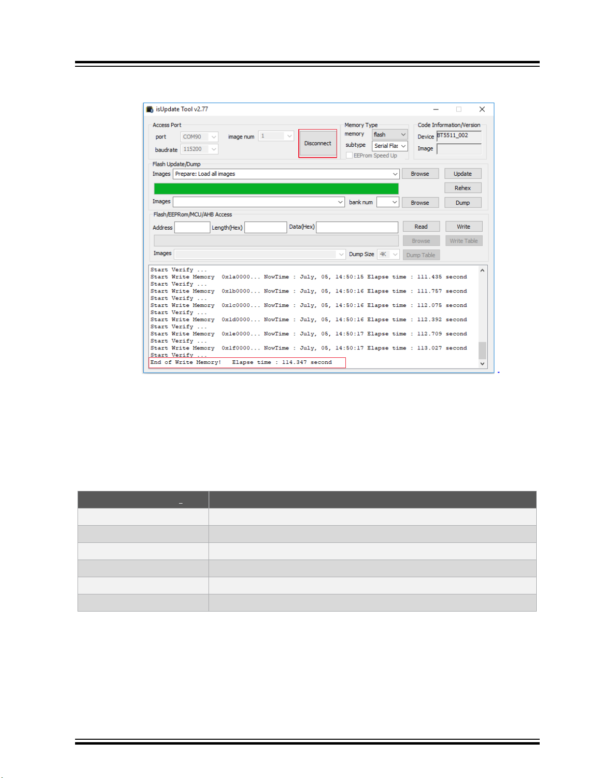
8. Click Disconnect and close the isUpdate tool after a successful firmware update.
Figure 5-5. Process Completed
BM83 EVB
Firmware Update
9. Remove the USB cable.
5.2 Firmware Update over USB
Use the isUpdate tool to perform a firmware update on the BM83 module through USB Device Firmware Upgrade
(DFU). The BM83 EVB should be in Application mode. For firmware update over the USB, the user must ensure the
hardware settings and configurations described in the following table.
Table 5-2. BM83 EVB Firmware Update Settings
Jumpers and Switches
JP304 Mount a jumper on “ADAP_IN” and “5V_ADAP_IN” pins of JP304 pin2 and pin3
JP203 Mount a jumper on 5V_USB and 5V_BT pins of JP203 pin1 and pin2
SW200 Put SW200 switch to 5V_USB position
SW300 Put SW300 switch to OFF position for Application Mode
J200 Connect the USB cable from a PC to J200
JP305 Mount a jumper on “3V3_IO” and “VDD_IO” pins of JP305
1. To locate these jumpers, switches, and power sources on the BM83 EVB, refer to Figure 3-2 and Figure 2-1.
Perform the following steps to load the firmware files onto the BM83 module using the isUpdate tool. Ensure that the
SW200 switch is in 5V_DC before connecting USB cable to J200 USB port.
1. Connect the BM83 EVB Micro-B USB port J200 over USB cable to the PC.
Note: Be sure to disconnect the 15V power supply before connecting the USB cable.
2. Observe that the Green LED (D209) and Red LED (D202) turn ON.
3. Set the SW200 switch to 5V_USB.
(1)
Description
© 2019 Microchip Technology Inc.
User Guide
DS50002902A-page 23
Page 24

BM83 EVB
Firmware Update
4. Open the isUpdate tool. Select the port as USB HID, set the baud rate to 115200, and image num to 1 as
shown in the following figure.
5. Click Connect.
Figure 5-6. Loading the Firmware Files
Note: In isUpdate tool, image num value must be equal to the number of images to be programmed on the
device. For example, to program firmware (image1), DSP (image2), and configuration (image3), the image
num value must be selected as 3.
© 2019 Microchip Technology Inc.
User Guide
DS50002902A-page 24
Page 25

BM83 EVB
Firmware Update
6. The message on console and the transition of Connect button to Disconnect indicates that the connection is
established successfully between the PC and the BM83 module.
Figure 5-7. Connection Established
© 2019 Microchip Technology Inc.
User Guide
DS50002902A-page 25
Page 26

BM83 EVB
Firmware Update
7. Once the connection is established, click Browse and open the firmware image provided in the release
package.
Note: The Embedded mode firmware images are available in the package, refer to www.microchip.com/
BM83.
Figure 5-8. Browsing and Loading the Files
8. Click Update to update the firmware and observe the progress.
© 2019 Microchip Technology Inc.
User Guide
DS50002902A-page 26
Page 27

Figure 5-9. Updating the Firmware
BM83 EVB
Firmware Update
9. Click Disconnect and close the isUpdate tool after a successful firmware update.
Figure 5-10. Process Completed
10. Remove the USB cable.
© 2019 Microchip Technology Inc.
User Guide
DS50002902A-page 27
Page 28
6. Customizing Module Parameters
6.1 Config Tool Setup
The IS208x_Config_GUI_Tool Config Tool setup is a configuration tool that allows the user to change the BM83
module parameters such as device name, Bluetooth Low Energy connection settings, LED configuration, enable/
disable Pairing mode and other functions.
Note: For this demonstration, Config Tool version IS208x_Config_GUI_Tool v1.0.11 is used. Refer to the
latest version at http://www.microchip.com/BM83. For additional details on the Config Tool, refer to IS208x Config
GUI Tool User’s Guide.
To configure the GUI parameters, perform the following steps:
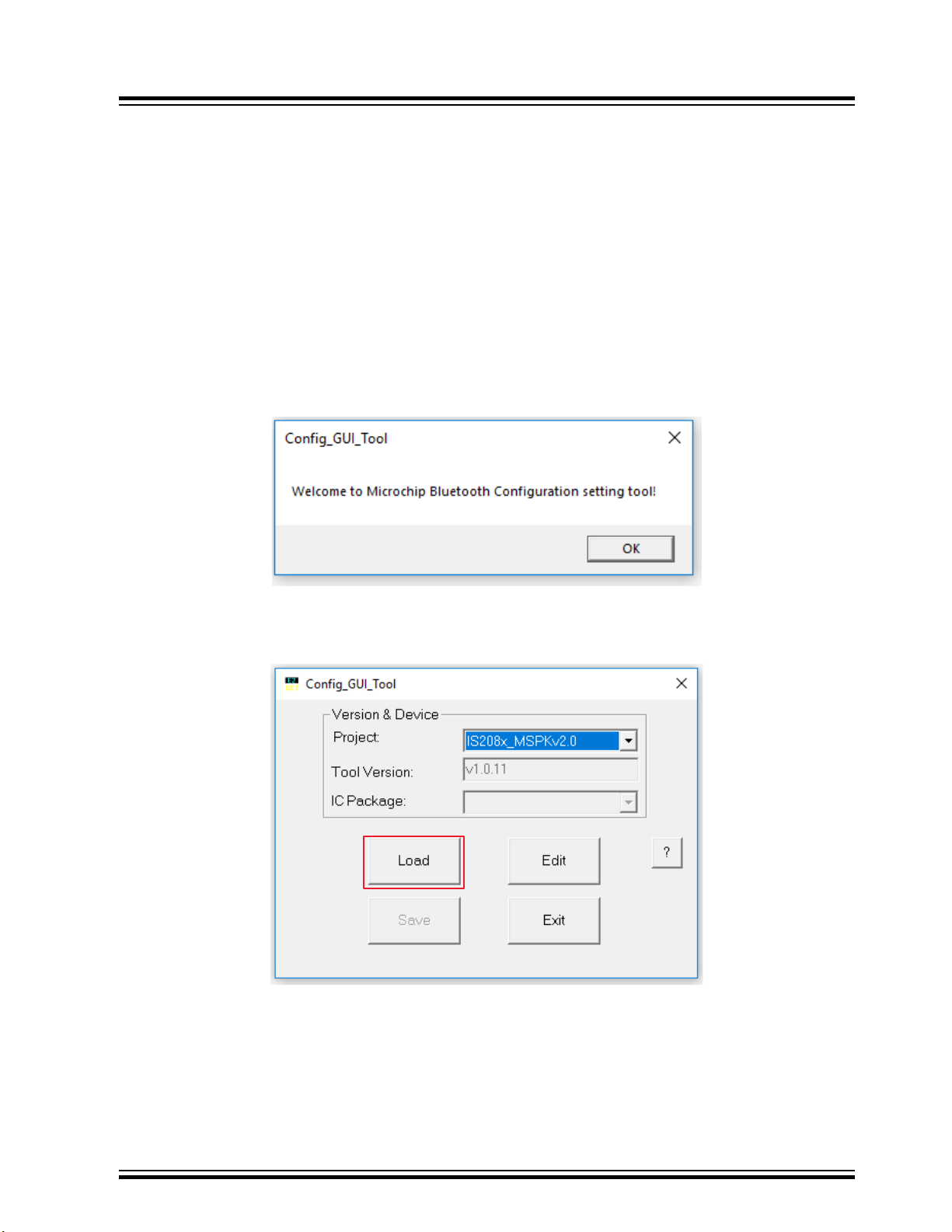
1. Open the Config Tool and click OK to configure the parameters.
Figure 6-1. Config Tool - Welcome Window
BM83 EVB
Customizing Module Parameters
2. In the Config Tool, click Load.
Figure 6-2. Config Tool
© 2019 Microchip Technology Inc.
User Guide
DS50002902A-page 28
Page 29

1
3
2
BM83 EVB
Customizing Module Parameters
3. From the Open window, select the default GUI parameters file (provided with the UI tool) for this module (BM83),
and then click Open, see the following figure.
Figure 6-3. Loading Default GUI Parameters
4. After loading the GUI parameters, click Edit to customize the GUI parameters on the Main Feature window.
Figure 6-4. Editing Parameters
© 2019 Microchip Technology Inc.
User Guide
DS50002902A-page 29
Page 30

BM83 EVB
Customizing Module Parameters
5. In the Main Feature window, the user can enable or disable the features required for their application. Select the
“Embedded Mode” option (see Figure 6-5) and click Next.
Note:
• For Host MCU mode, select the “Host MCU Mode”.
• For Embedded mode, select the “Embedded Mode”.
Figure 6-5. Main Feature Settings
© 2019 Microchip Technology Inc.
User Guide
DS50002902A-page 30
Page 31

BM83 EVB
Customizing Module Parameters
6. In the System and Functional Settings window, go to Sys. Setup1 tab to power ON/OFF the Bluetooth system.
Select MFB Power ON/OFF in the “Power Switch Type” section.
Figure 6-6. Options in Sys. Setup1 Tab
© 2019 Microchip Technology Inc.
User Guide
DS50002902A-page 31
Page 32
BM83 EVB
Customizing Module Parameters
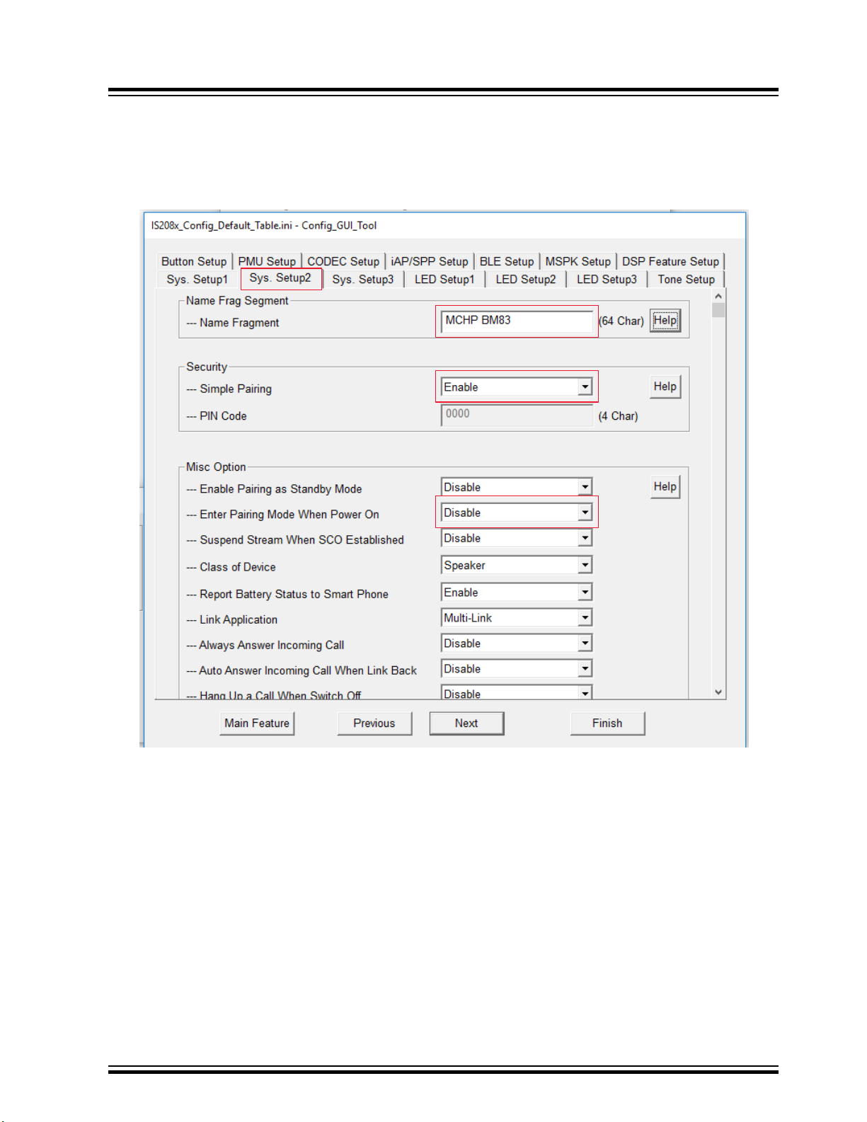
7. In the Sys. Setup2 tab, the user can change the following as shown in the Figure 6-7:
• Device name – add the device name in the text box available under “Name Frag Segment” section.
• Pairing mechanism – select Enable for the pairing mechanism available under “Simple Pairing” drop-down
menu.
Figure 6-7. Options in Sys. Setup2 Tab
© 2019 Microchip Technology Inc.
User Guide
DS50002902A-page 32
Page 33
BM83 EVB
Customizing Module Parameters
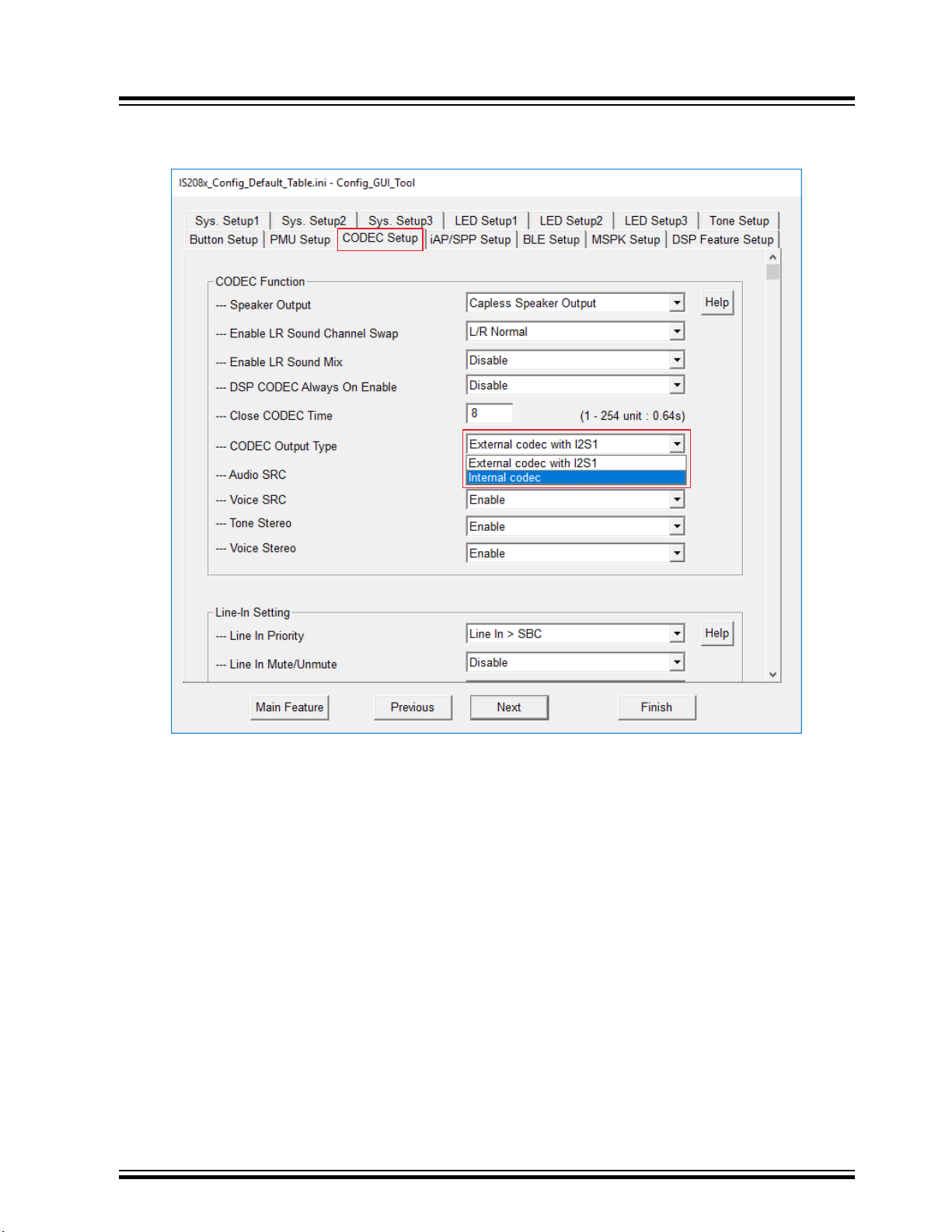
8. In the CODEC Setup tab, select Internal codec from the “CODEC Output Type” drop-down menu.
Figure 6-8. Options in CODEC Setup Tab
© 2019 Microchip Technology Inc.
User Guide
DS50002902A-page 33
Page 34

BM83 EVB
Customizing Module Parameters
9. Click Finish after modifying these settings. IS208x_DSP_GUI_Tool window opens as shown in the following figure.
Figure 6-9. Main Function Tab
© 2019 Microchip Technology Inc.
User Guide
DS50002902A-page 34
Page 35

BM83 EVB
Customizing Module Parameters
10. In the Voice Function tab, the user can set the required parameters as highlighted in the following figure.
Figure 6-10. Voice Function Tab
© 2019 Microchip Technology Inc.
User Guide
DS50002902A-page 35
Page 36

BM83 EVB
Customizing Module Parameters
11. In the Audio Function tab, the user can set the required parameters as highlighted in the following figure.
Figure 6-11. Audio Function Tab
© 2019 Microchip Technology Inc.
User Guide
DS50002902A-page 36
Page 37

BM83 EVB
Customizing Module Parameters
12. In the I2S/PCM tab, the user can set the required parameters as highlighted in the following figure.
Figure 6-12. I2S/PCM Tab
© 2019 Microchip Technology Inc.
User Guide
DS50002902A-page 37
Page 38

2
1
BM83 EVB
Customizing Module Parameters
13. Click Save to save the changed parameters onto a file and click OK on the confirmation window (see the
following figure).
Figure 6-13. Saving Parameters
© 2019 Microchip Technology Inc.
User Guide
DS50002902A-page 38
Page 39
Customizing Module Parameters
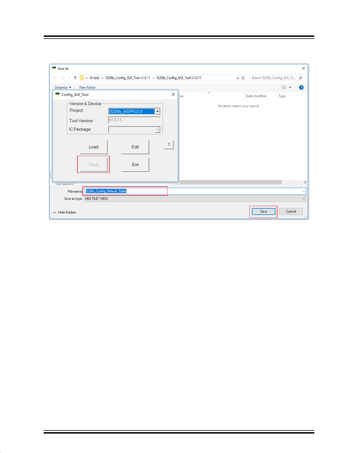
14. Click Save to save the file in .HEX format as shown in the following figure.
Figure 6-14. Save as a HEX File
BM83 EVB
© 2019 Microchip Technology Inc.
User Guide
DS50002902A-page 39
Page 40
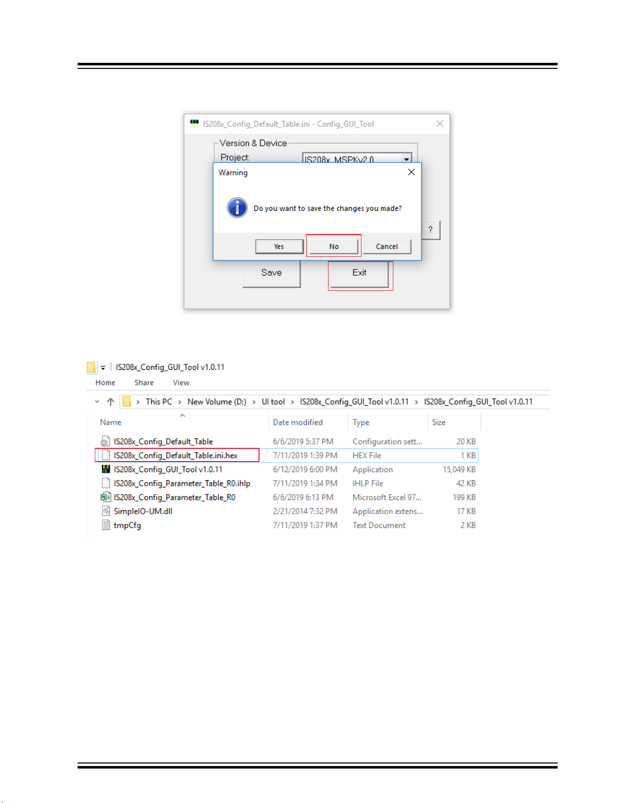
15. Click Exit followed by No as shown in the following figure.
1
2
Figure 6-15. Exiting the GUI Tool
BM83 EVB
Customizing Module Parameters
After saving the file, the user can see an additional .hex file in the GUI tool folder as shown in the following figure.
Figure 6-16. Generated HEX File
Note: For Embedded mode with internal codec demo, refer to 14. Appendix H: Bluetooth Audio Demonstration in
Embedded Mode with Internal Codec.
© 2019 Microchip Technology Inc.
User Guide
DS50002902A-page 40
Page 41
DP
DM
USB CONNECTOR
5V_BT
0.1uF
16V
0603
C211
1uF
16V
0603
C212
100R
FB200
100R
FB201
5V
D207
A
1
K
2
5V
SOD-882
PESD5V0X1BL,315
D208
CAD Note:
ESD Diod es to be p laced closest
to the US B connector
TP LOOP Red
TP203
GND_SHLD
GND_SHLD
GND_SHLD
5V
D206
0R
0603
R206
0R
0603
R207
ID
4
VBUS
1
GND
5
D-
2
D+
3
0
USB2.0 MICRO-B F EMALE
J200
BM83 Carrier Board USB
MODULE INTERFACE
AOHPM
AOHPL
MIC_P2
MIC_N2
AOHPR
AIL
AIR
MIC_N1
MIC_P1
MIC_BIAS
DP
DM
P3_4
P3_2
P0_2
P0_3
P0_5
P2_7
P0_6
P3_4
P0_2
P0_6
P0_3
P0_5
P1_6
LED1
LED2
RST_N
LED1
LED2
MIC_BIAS
P3_5
SYS_PWR
VDD_IO
BAT_IN
ADAP_IN
SK1_AMB_DET
SK2_KEY_AD
MFB
RFS1
DR1
DT1
SCLK1
MCLK1
ADAP_IN
BAT_IN
SYS_PWR
VDD_IO
MFBSK1_AMB_DET
SK2_KEY_AD
HCI_TXD
HCI_RXD
P3_5
P0_0
P0_0
P0_1
P1_3
P1_2
P0_1
DMIC2_R
DMIC2_L
P2_6
P0_7
P3_7
P0_7
P3_7
P1_6
P2_3
P2_6
RFS1
SCLK1
DR1
DT1
MCLK1
RST_N
DP
DM
P2_7
P1_3
P1_2
P2_3
DMIC1_R
DMIC1_L
DMIC_CLK
GPIO_1
GPIO_2
PWM
LED3
CLDO_O
CODEC_VO
RFLDO_O
BK1_O_1V5
BK2_O_1V8
LDO31_VO
DMIC1_L
DMIC_CLK
DMIC1_R
DMIC2_R
DMIC2_L
P3_2
0.1uF
16V
0603
C315
0.1uF
16V
0603
C316
SYS_PWR VDD_IO
1
TP300
LDO31_VO
1 2
3 4
5 6
7 8
9 10
11
68
69 70
71 72
73 74
75
20
21 22
23 24
25 26
27 28
29 30
31 32
33 34
35 36
37 38
39 40
41 42
43 44
45 46
47 48
49 50
51 52
53 54
55 56
57 58
59 60
61 62
63 64
65 66
67
M1
M2
EDGE 67 P Female
J300
Appendix A: BM83 EVB Reference Schematics
7. Appendix A: BM83 EVB Reference Schematics
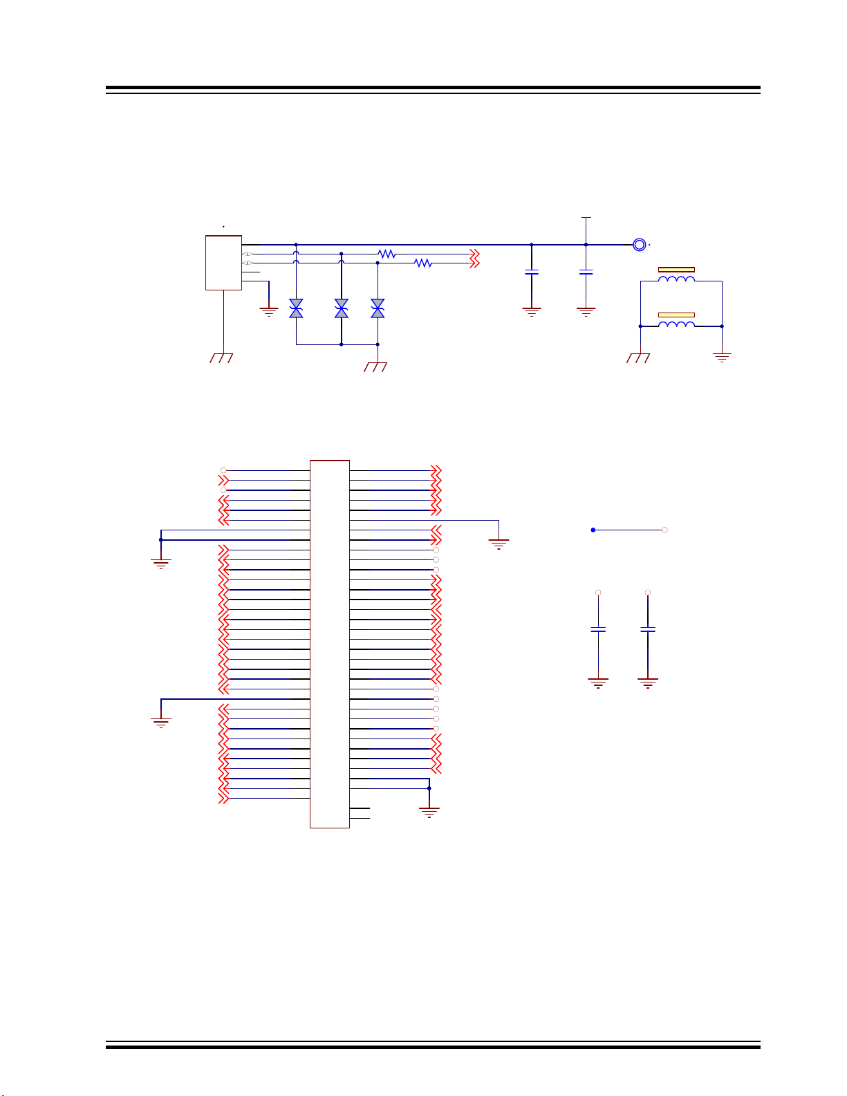
Figure 7-1. USB Connector Schematic
Figure 7-2. BM83 Module Interface (over BM83 Carrier Board)
BM83 EVB
© 2019 Microchip Technology Inc.
User Guide
DS50002902A-page 41
Page 42

Figure 7-3. 5V Power Switch
5V_DC
5V_USB
5V_ADAP_IN
5V POWER SWITCH
GREEN
D209
1K
0603
R208
0.1uF
16V
0603
C213
1uF
16V
0603
C214
TP LOOP Red
TP204
GND_SHLD
NOTE :
Recommend ed to switch to
5V_DC mode for audio
applications
In pu t R ange for
ADAP _IN : 4. 6V to 6V
5V
D205
5V_DC
5V_USB
1
2
3
TOGGLE SPDT
SW200
MCP_OSCINMCP_OSCOUT
USB TO UART CONVERTER
1 3
12Mhz
X600
12pF
50V
0603
C60912pF
50V
0603
C608
RST
4
GP7/TxLED
5
GP6/RxLED
6
GP5
7
GP4
8
GP3
9
GP2
14
GP1/USB-CFG
15
GP0/SSPND
16
CTS
13
RTS
11
RX
12
TX
10
VDD
1
VSS
20
OSC1
2
OSC2
3
D+
19
D-
18
VUSB
17
MCP2200
U602
EXT_3V3
0.1uF
0603
C605
0R
0603
R601
MCP_OSCIN
MCP_OSCOUT
EXT_3V3
0.1uF
16V
0603
C607
10k
0603
1%
R603
10k
0603
1%
DNP
R602
5V_MCP
10k
0603
1%
DNP
R606
MCP_TX
MCP_RX
MCP_D+
MCP_D-
EXT_3V3
0.1uF
16V
0603
C606
0R
0603
R605
1
TP600
1
TP601
1
TP602
1
TP603
1
TP604
1
TP605
1
TP606
1
TP607
Figure 7-4. USB-UART Converter
BM83 EVB
Appendix A: BM83 EVB Reference Schematics
© 2019 Microchip Technology Inc.
User Guide
DS50002902A-page 42
Page 43

Figure 7-5. Reset IC
RST_N
RESET IC (OPTIONAL)
0.1uF
16V
0603
C301
4.7k
0603
1%
R307
VDD_IO
SYS_PWR
VDD3VOUT
1
VSS
2
MCP111 DNP
U300
RST_N
RST_N
RESET
5V_ADAP_IN
1uF
16V
0603
C704
0R
0603
DNP
R701
RST_N
1 4
2 3
TACT SPST
SW700
2k
0603
5%
R702
GND_SHLD
PESD5V0S1BA
SOD-323
D700
15pF
50V
0603
C700
1
3
2
MMBT3904
Q700
Figure 7-6. Reset
BM83 EVB
Appendix A: BM83 EVB Reference Schematics
© 2019 Microchip Technology Inc.
User Guide
DS50002902A-page 43
Page 44
Figure 7-7. Push Button Interface
MFB/Power
VOL+
VOL-PLAY/PAUSE
REVFWD
PUSH BUTTON
1 4
2 3
TACT SPST
SW702
VOL_UP
1 4
2 3
TACT SPST
SW705
VOL_DN
REV
1 4
2 3
TACT SPST
SW708
PLAY/PAUSE
1 4
2 3
TACT SPST
SW704
FWD
1 4
2 3
TACT SPST
SW707
MFB
1 4
2 3
TACT SPST
SW701
SYS_PWR
PAIRING
1 4
2 3
TACT SPST
SW703
PAIRING
GND_SHLD
GND_SHLD GND_SHLD
GND_SHLD
GND_SHLD
GND_SHLD
GND_SHLD
PESD5V0S1BA
SOD-323
D701
PESD5V0S1BA
SOD-323
D702
PESD5V0S1BA
SOD-323
D703
PESD5V0S1BA
SOD-323
D705
PESD5V0S1BA
SOD-323
D704
PESD5V0S1BA
SOD-323
D707
PESD5V0S1BA
SOD-323
D708
0R
0603
R700
MFB
15pF
50V
0603
C701
15pF
50V
0603
C702
15pF
50V
0603
C703
15pF
50V
0603
C705
15pF
50V
0603
C706
15pF
50V
0603
C708
15pF
50V
0603
C709
P0_6
1 4
2 3
TACT SPST
SW711
GND_SHLD
PESD5V0S1BA
SOD-323
D710
15pF
50V
0603
C712
SELECT
BM83 EVB
Appendix A: BM83 EVB Reference Schematics
© 2019 Microchip Technology Inc.
User Guide
DS50002902A-page 44
Page 45
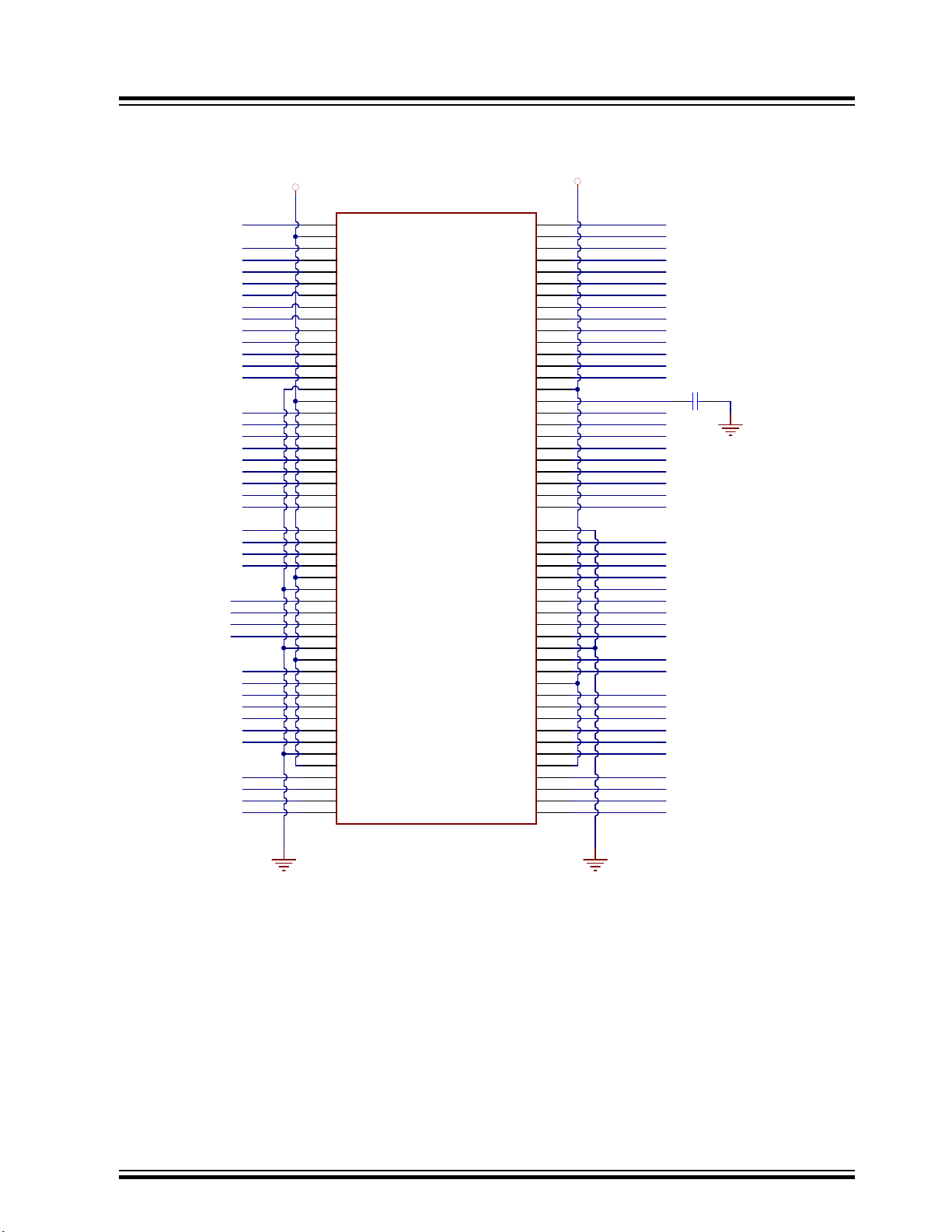
Figure 7-8. PIM Socket
48
48
4
4
21
21
22
22
23
23
72
72
71
71
70
70
69
69
41
41
42
42
43
43
1
1
44
44
10
10
5
5
100
100
24
24
25
25
82
82
83
83
84
84
85
85
86
86
87
87
81
81
80
80
91
91
90
90
9
9
15
15
79
79
78
78
77
77
76
76
11
11
6
6
99
99
36
36
35
35
75
75
96
96
74
74
73
73
12
12
7
7
50
50
49
49
30
30
31
31
29
29
28
28
34
34
33
33
32
32
40
40
39
39
98
98
97
97
95
95
94
94
8
8
68
68
65
65
13
13
89
89
88
88
56
56
55
55
54
54
53
53
64
64
67
67
66
66
14
14
63
63
62
62
61
61
52
52
51
51
60
60
59
59
58
58
57
57
3
3
2
2
26
26
27
27
38
38
37
37
93
93
92
92
16
16
17
17
47
47
45
45
46
46
18
18
19
19
20
20
PIM 100 Pin Male TH
U400
RG15
RE5
RE6
RE7
RC1
MCU_SDI
PIM_MCLR
MCU_BCLK
MCU_SDO
MCU_P20
3V3_PIC
RA0
RE8
RB5
MCU_REC
FUNC2_MCU
FUNC1_MCU
MCU_PLAY/PAUSE
MCU_REV
MCU_FWD
MCU_VOL_DN
MCU_VOL_UP
RA1
MCU_LED1
MCU_LED6
MCU_LED5
MCU_LED4
MCU_LED3
MCU_LED2
MCU_LED8
MCU_LED7
TXD_MCU
RXD_MCU
RST_MCU
FLASH_CS#
MCU_VBUS
3V3_PIC
MCU_DP
MCU_DM
RA3
RA2
OSC2
OSC1
MCU_EXT1
RPD9
SCK1
MCU_SCL
MCU_SDA
RC14
RC13
RD11
RD8
MCU_EXT2
MCU_EXT3
MCU_EXT4
MCU_EXT5
MCU_EXT6
RD4
MCU_EXT7
MCU_EXT8
RF1
RF0
MFB_MCU
RG1
RPE3
RE4
RG13
RE2
RG14
RG12
RE0
RE1
RA7
RC3
RC4
RC2
RTSn_MCU
CTSn_MCU
100 Pin PIM Socket
10uF
16V
0805
C409
MCU_SLEEP
MCU_MUTE
MCU_PROT_N
MCU_IC_N
PAIRING_MCU
UTX_IND
LINE_IN_DET_MCU
PGEC1
PGED1
BM83 EVB
Appendix A: BM83 EVB Reference Schematics
© 2019 Microchip Technology Inc.
User Guide
DS50002902A-page 45
Page 46

Figure 7-9. Microphone
MIC_P2
MIC_N2
MIC2
MICROPHONE INPUT
1
2
3
HDR-2.54 Male 1x3
JP502
0603
DNP
C516
1
TP503
1
TP504
1uF
16V
0603
C518
1uF
16V
0603
C513
1uF
16V
0603
C514
2.2k
0603
1%
R506
MIC_P1
MIC_N1
MIC1
1
2
3
HDR-2.54 Male 1x3
JP500
0603
DNP
C504
MIC_P1
MIC_N1
1
TP500
1
TP501
1uF
16V
0603
C506
1uF
16V
0603
C500
1uF
16V
0603
C502
2.2k
0603
1%
R500
MIC_N2
MIC_P2
MIC_N1
MIC_P1
MIC_BIAS
MIC_BIAS
5
1
4
3
2
JACK Stereo Phone 3.5mm
P500
5
1
4
3
2
JACK Stereo Phone 3.5mm
P502
Note:
Single En d Type MIC : R505=0E
Differential Type MIC: R505=2.2K
Note:
Single En d Type MIC : R508=0E
Differential Type MIC: R508=2.2K
0R
0603
R508
0R
0603
R505
BM83 EVB
Appendix A: BM83 EVB Reference Schematics
© 2019 Microchip Technology Inc.
User Guide
DS50002902A-page 46
Page 47

Figure 7-10. MCU to Bluetooth Switch
MFB_MCU
TXD_MCU
RXD_MCU
RST_MCU
MCU_BCLK
MCU_SDI
FLASH_CS#
MFB
HCI_RXD
HCI_TXD
RST_N
P3_4
SCLK1
P3_7
MCU to BT Switch
MCU
BT
33R 06035%R423
33R 06035%R424
33R 06035%R425
33R 06035%R426
33R 06035%R427
33R 06035%R428
33R 06035%R422
33R 06035%R420
33R 06035%R419
33R 06035%R418
33R 06035%R416
33R 06035%R417
RFS1
DT1
MCU I2S IN BT I2S OUT
P2_6
P0_0
UTX_IND
P2_3
CTSn_MCU
RTSn_MCU
MCU_P20
FUNC1_MCU
11A
22A
33A
44A
55A
66A
DIP 6 SPST
SW402
11A
22A
33A
44A
55A
66A
DIP 6 SPST
SW403
SCK1
MCU_EXT1
SCLK1_DSP
DT1_DSP
RFS1_DSP
MCU vs. BT SWITCH
DSP I2S
33R 06035%R400
33R 06035%R401
33R 06035%R402
MCU_EXT1
LINE_IN_DET_MCULINE_IN_DET
MCLK1_DSP
RPD9
33R 06035%R434
RPE3
P3_2
11A
22A
33A
44A
55A
66A
DIP 6 SPST
SW400
BM83 EVB
Appendix A: BM83 EVB Reference Schematics
© 2019 Microchip Technology Inc.
User Guide
DS50002902A-page 47
Page 48
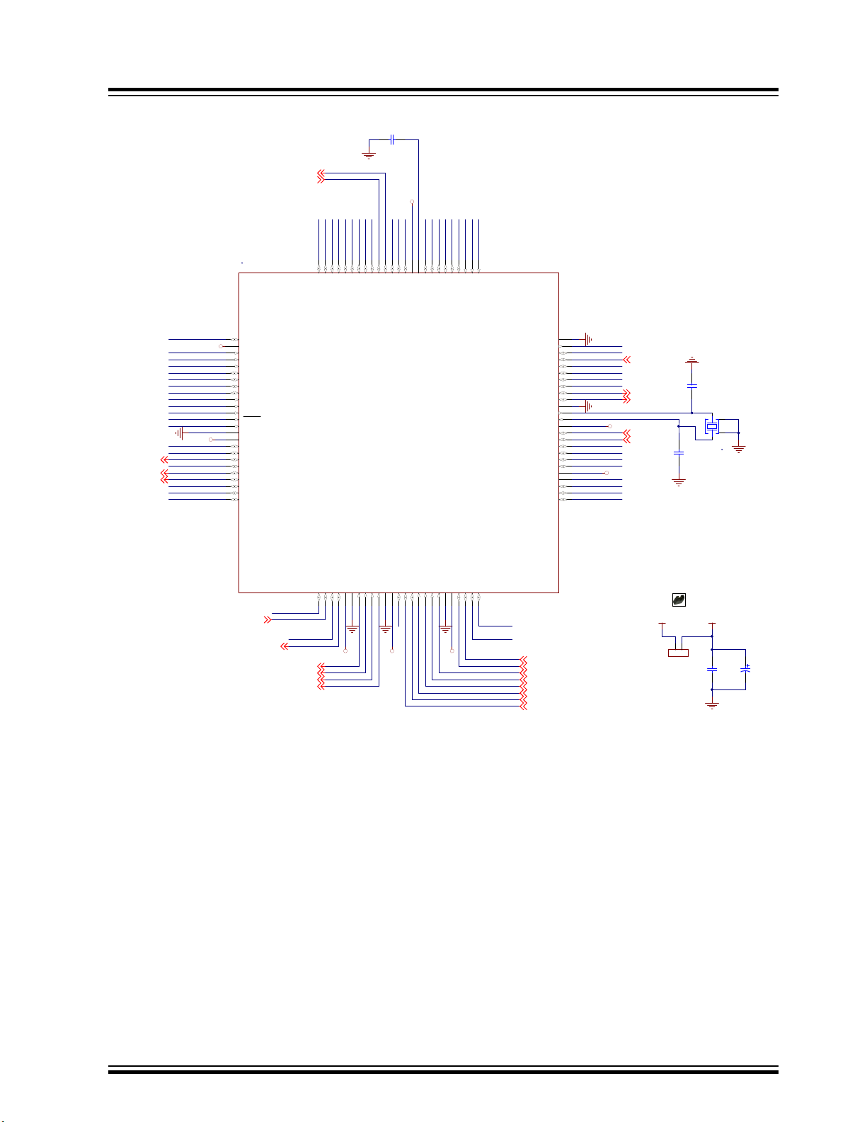
Figure 7-11. PIC32MX450F256L Pin Configuration
PIC32_MCLR
MFB_MCU
OSC2
OSC1
MCU_SDI
MCU_SDO
MCU_BCLK
RC3
RC4
RC2
MCU_P20
RA0
3V3_PIC
3V3_PIC
3V3_PIC
3V3_PIC 3V3_PIC3V3_PIC
3V3_PIC
3V3_PIC
MCU_LED1
MCU_LED2
MCU_LED3
MCU_LED4
MCU_EXT1
MCU_MUTE
MCU_SLEEP
MCU_IC_N
MCU_LED5
MCU_LED6
MCU_LED7
MCU_LED8
MCU_VOL_UP
MCU_FWD
MCU_VOL_DN
MCU_REV
MCU_PLAY/PAUSE
MFB_MCU
(UART_TXD)
(UART_RXD)
10uF
16V
0805
C408
RG15
RE5
RE6
RE7
RC1
RE8
RB5
FUNC2_MCU
FUNC1_MCU
MCU_PLAY/PAUSE
MCU_REV
MCU_FWD
MCU_VOL_DN
MCU_VOL_UP
MCU_LED8
MCU_LED7
MCU_LED6
MCU_LED5
MCU_LED4
MCU_LED3
MCU_LED2
MCU_LED1
RC14
RC13
RD8
RPE3
RE4
RG13
RE2
RG14
RG12
RE0
RE1
RA7
RF1
RF0
10pF
50V
0603
C412
10pF
50V
0603
C415
RG1
MCU_SCL
MCU_SDA
MCU_IC_N
100uF
25V
C417
MCU_VBUS
RA1
10uF
25V
0805
C416
PAIRING_MCU
PAIRING_MCU
MCU_PROT_N
SCK1
RPD9
MCU_EXT1
MCU_SDA
MCU_SCL
MCU_SLEEP
MCU_MUTE
RA3
RA2
MCU_DP
MCU_DM
CTSn_MCU
FLASH_CS#
RST_MCU
MCU_VBUS
TXD_MCU
RXD_MCU
MCU_EXT8
MCU_EXT7
RTSn_MCU
RD4
MCU_EXT6
MCU_EXT5
MCU_EXT4
MCU_EXT3
MCU_EXT2
VCAP
MCU_REC
MCU_REC
LINE_IN_DET _MCU
MCU_PROT_N
5V_ADAP_IN
1 2
HDR-2.54 Male 1x2
JP401
RD11
13
16MHz
X400
RG15
1
VDD
2
AN22/RPE5/PM D5/RE5
3
AN23/PMD6/RE 6
4
AN27/PMD7/RE 7
5
RPC1/RC1
6
RPC2/RC2
7
RPC3/RC3
8
RPC4/CTED7/RC4
9
AN16/C1IND/ RPG6/SCK2/PMA5/RG6
10
AN17/C1INC/RP G7/PMA4/RG7
11
AN18/C2IND/ RPG8/PMA3/RG8
12
MCLR
13
AN19/C2INC/RP G9/PMA2/RG9
14
VSS
15
VDD
16
17 TMS/CTED1/RA0
17
RPE8/RE8
18
RPE9/RE9
19
AN5/C1INA/RP B5/VBUSON/RB5
20
PGEC2/AN6/RPB6/RB6
26
PGED2/AN7/RPB7/CTED3/RB727VREF-/CVREF-/PMA7/RA9
28
VREF+/CVREF+/PMA6/RA10
29
AVDD
30
AVSS
31
AN8/RPB8/CTED10/RB8
32
AN9/RPB9/CTED4/RB9
33
AN10/RPB10/CTED11/PMA13/RB10
34
AN11/PMA12/RB1135VSS
36
VDD
37
TCK/CTED2/RA138RPF13/RF1339RPF12/RF1240AN12/PMA11/RB1241AN13/PMA10/RB1342AN14/RPB14/CTED5/PMA1/RB14
43
AN15/RPB15/OCFB/CTED6/PMA0/RB1544VSS
45
VSS
75
SOSCO/RPC14/T1CK /RC14
74
SOSCI/RPC13/RC13
73
RPD0/INT0/RD0
72
RPD11/PMCS1/RD11
71
RPD10/SCK1/PMCS2/ RD10
70
RPD9/RD9
69
RPD8/RTCC/RD8
68
SDA1/RPA15/RA15
67
SCL1/RPA14/RA14
66
VSS
65
OSC2/CLKO/RC15
64
OSC1/CLKI/RC12
63
VDD
62
TDO/RA5
61
TDI/CTED9/RA 4
60
SDA2/RA3
59
SCL2/RA2
58
D+
57
D-
56
AN21/PMD4/RE4
100
RPE3/PMD3/RE3
99
AN20/CTPLS/PMD2/RE2
98
TRD0/RG13
97
TRD1/RG12
96
TRD2/RG14
95
PMD1/RE194PMD0/RE0
93
TRD3/CTED8/RA7
92
TRCLK/RA6
91
RPG0/PMD8/RG0
90
RPG1/PMD9/RG1
89
RPF1/PMD10/RF1
88
RPF0/PMD11/RF0
87
VDD
86
VCAP
85
PMD15/RD7
84
PMD14/RD6
83
RPD5/PMRD/RD5
82
RPD4/PMWR/RD4
81
AN4/C1INB/RB4
21
PGED3/AN3/ C2INA/RPB3/RB3
22
PGEC3/AN2/C2 INB/RPB2/CTED13/RB2
23
PGEC1/AN1/RPB 1/CTED12/RB1
24
PGED1/AN0/ RPB0/RB0
25
VDD
46
RPD14/RD14
47
RPD15/RD15
48
RPF4/PMA9/RF4
49
RPF5/PMA8/RF5
50
VUSB3V3
55
VBUS
54
RPF8/RF8
53
RPF2/RF2
52
USBID/RF3
51
PMD13/RD13
80
RPD12/PMD12/RD12
79
AN26/RPD3/RD3
78
AN25/RPD2/RD2
77
AN24/RPD1/RD1
76
PIC32MX450F256 L
U402
LINE_IN_DET_MCU
UTX_IND
PGEC1
PGED1
Shunt 2.54mm 1x2
JP403
BM83 EVB
Appendix A: BM83 EVB Reference Schematics
© 2019 Microchip Technology Inc.
User Guide
DS50002902A-page 48
Page 49

Figure 7-12. LED Interface
MCU_LED1
MCU_LED2
MCU_LED3
MCU_LED4
MCU_LED5
MCU_LED6
MCU_LED7
MCU_LED8
LED(MCU)
200R
0603
1%
R406
200R
0603
1%
R409
200R
0603
1%
R411
200R
0603
1%
R412
200R
0603
1%
R413
200R
0603
1%
R414
200R
0603
1%
R415
200R
0603
1%
R421
GREEN
D401
GREEN
D402
GREEN
D403
GREEN
D404
GREEN
D405
GREEN
D406
GREEN
D407
GREEN
D411
3V3_GEN
BM83 EVB
Appendix A: BM83 EVB Reference Schematics
© 2019 Microchip Technology Inc.
User Guide
DS50002902A-page 49
Page 50

Figure 7-13. ICSP Interface
GND
GND
MCU_RESET
TARGET SELECT On board MCU or PIM
ICSP
3V3_PIC
3V3_PIC
1 4
2 3
TACT SPST
SW401
PESD5V0S1BA
D400
1K
0603 1%
R405
10k
0603
1%
R404
0.1uF
50V
0603
C413
0.1uF
50V
0603
C414
MCLR
JS202011SCQN
6
4
5
1
2
3
S400
GND
PIM_MCLR
PIC32_MCLR
3V3_GEN 3V3_PIC
1 2
HDR-2.54 Male 1x2
JP400
VDD
8
VSS
4
CE
1
WP
3
SCK
6
HOLD
7
SO
2
SI
5
SST25VF080B
U401
3V3_PIC
0.1uF
50V
0603
C410
20k
0603
5%
R403
3V3_PIC
MCU_SDO
MCU S-Flash
3V3_PIC
10uF
25V
0805
C411
MCU_BCLK
MCU_SDI
FLASH_CS#
PGEC1
PGED1
Shunt 2. 54mm 1x2
JP402
1
2
3
4
5
6
HDR-2.54 Male 1x6
J400
1
2
3
4
5
6
7
HDR-2.54 Male 1x7
J404
1
2
3
4
5
6
7
HDR-2.54 Male 1x7
J405
BT DSP
RFS1_DSP
SCLK1_DSP
DT1_DSP
DR1_DSP
MCLK1_DSP
RFS1
DR1
DT1
SCLK1
Serial clock
Serial data receive
Serial data transmit
I2S HEADER
33R 06035%R431
33R 06035%R429
33R 06035%R432
33R 06035%R433
Receive Frame Sync
33R 06035%R430
MCLK1
3V3_IO 3V3_IO
BM83 EVB
Appendix A: BM83 EVB Reference Schematics
Figure 7-14. I2S Header
© 2019 Microchip Technology Inc.
User Guide
DS50002902A-page 50
Page 51

Figure 7-15. I2C Interface
3V3_IO
P1_3
P1_2
0R
0603
R325
P3_2
3V3_IO
0.1uF
16V
0603
C313
1uF
16V
0603
C314
I2C_INTERFACE
A0
1
SDA
5
A2
3
A1
2
WP
7
VSS
4
SCL
6
VCC
8
24LC64
U301
3V3_IO
1
2
3
HDR-2.54 M ale 1x3
JP307
P2_3
P2_3
1
2
3
HDR-2.54 M ale 1x3
JP308
P2_6
P2_6
P1_2
P1_3
JP307, JP308
1-2
2-3
SW I2C
HW I2C (Default)
1 2
HDR-2.54 M ale 1x2
JP309
P2_3
P2_3
P2_6
P2_6
Note:
JP309 is Test Point for SW I2C IOs .
To be used to c onnect to Ext Codec (J 402)
while us ing SW I2C .
To be placed near t he Ext Cod ec section
I2C_SDA
I2C_SCL
Shunt 2. 54mm 1x2
JP315
Shunt 2. 54mm 1x2
JP316
1.5k
0603
1%
R300
1.5k
0603
1%
R301
3V3_IO
P1_3
P1_2
0R
0603
R325
P3_2
3V3_IO
0.1uF
16V
0603
C313
1uF
16V
0603
C314
I2C_INTERFACE
A0
1
SDA
5
A2
3
A1
2
WP
7
VSS
4
SCL
6
VCC
8
24LC64
U301
3V3_IO
1
2
3
HDR-2.54 M ale 1x3
JP307
P2_3
P2_3
1
2
3
HDR-2.54 M ale 1x3
JP308
P2_6
P2_6
P1_2
P1_3
JP307, JP308
1-2
2-3
SW I2C
HW I2C (Default)
1 2
HDR-2.54 M ale 1x2
JP309
P2_3
P2_3
P2_6
P2_6
Note:
JP309 is Test Point for SW I2C IOs .
To be used to c onnect to Ext Codec (J 402)
while us ing SW I2C .
To be placed near t he Ext Cod ec section
I2C_SDA
I2C_SCL
Shunt 2. 54mm 1x2
JP315
Shunt 2. 54mm 1x2
JP316
1.5k
0603
1%
R300
1.5k
0603
1%
R301
BT----DSP----MCU INTERFACE
MCU_IC_N
MCU_SLEEP
MCU_MUTE
MCU_SCL
MCU_SDA
MCU_PROT_N
P0_2
P2_7
P0_5
P1_6
P0_01
2
3
4
5
6
7
HDR-2.54 Male 1x7
J401
1
2
3
4
5
6
7
HDR-2.54 Male 1x7
J402
1
2
3
4
5
6
7
HDR-2.54 Male 1x7
J403
BT
DSP
MCU
P1_2
P1_3
SCL_DSP
SDA_DSP
PROT_N_DSP
DSP_IC_N_DSP
SLEEP_N_DSP
MUTE_N_DSP
DSP_IRQ_N
JP406
JP407
JP405
JP404
Embedded Mode Jumper Settings
J401 J402#1Jumper to be Mount
JP404
#4
#5
#7
#1
#4
#5
#7
JP405
JP406
JP407
GND
VDD_DIGMIC
DM1_SELECT
GND
VDD_DIGMIC
DM2_SELECT
1
2
3
HDR-2.54 Mal e 1x3
J505
1
2
3
HDR-2.54 Mal e 1x3
J504
1
2
3
4
5
HDR-2.54 Mal e 1x5
J503 VDD _DIGMIC
DM1_SELECT
1
2
3
4
5
HDR-2.54 Mal e 1x5
J502 VDD_D IGMIC
GND
DM2_SELECT
DIGITAL_MIC
DMIC1_R
DMIC1_L
GND
DMIC1_L
DMIC1_R
DMIC1_CLK
DMIC1_CLKShunt 2.5 4mm 1x2
JP509
Shunt 2.5 4mm 1x2
JP511
100R
FB500
DMIC2_CLK
DMIC1_CLK
100R
FB501
DMIC_CLK
DMIC_CLK
Figure 7-16. BT –DSP–MCU Interface
BM83 EVB
Appendix A: BM83 EVB Reference Schematics
Figure 7-17. Digital MIC and Interface
© 2019 Microchip Technology Inc.
User Guide
DS50002902A-page 51
Page 52

Figure 7-18. CPU JTAG Header
CPU_JTAG
RST_N
GND
3V3_IO
P1_2
P1_3
EMUD_CP U
EMUC_CP U
0.1uF
16V
0603
C311
1
2
3
4
5
6
HDR-2.54 Male 1x6
J301
XPRO_INTERFACE
3V3_IO
Xplained Pr o sta ndar d extension head er
I2C_SDA I2C_SCL
UART_RX UART_TX
SPI_SS_A SPI_MOSI
SPI_MISO SPI_SCK
IRQ/GPIO SPI_SS_B/GPIO
0R 0 603R309
0R 0 603R314
0R 0 603R312
0R 0 603R315
0R 0 603R310
0R 0 603R317
0R 0 603R319
0R 0 603R316
0R 0 603R318
0R 0 603R313
4.7uF
6.3V
0603
C302
SK2_KEY_AD
HOST_WAK EUP
UART_RTS
CHIP_EN
IRQN
SPI_SSN
BT_UART1 _TXD
SPI_MISO
HCI_TXDHCI_RXD
P0_6
0R 0 603R324
SK1_AMB_DET
GPIO_1 GPIO_2
I2C_SDA I2C_SCL
GPIO_1 GPIO_ 2
ADC+ ADC-
SK1_AMB_DE TSK2_KEY_ AD
PWM
PWM+
P1_6
P3_5
P0_7
P2_3
P2_6
P0_0
0R 0 603R326 0R 0 603R327
0R 0 603R328
1
2
3
4
5
6
7
8
9
10
11
12
13
14
15
16
17
18
19
20
HDR-2.54 Male 2x10 RA Rotated 180
J304
MCU_VOL_UP
MCU_FWD
MCU_REV
MCU_VOL_DN
PAIRING_MCU
MCU_PLAY/PAUSE
12345678
HDR-2.54 Male 1x8
J700
12345678
HDR-2.54 Male 1x8
J702
VOL_UP
FWD
REV
VOL_DN
PAIRING
PLAY/PAUSE
12345678
HDR-2.54 Male 1x8
J701
BUTTON CO-USE JUMPER
MCU BUTTON BM8X_CARRIER_BOARD
CAD Note:
Place these 3 headers close to each other
J 701<-->J 702 Default C on figu r ation
J 701<-->J 700 For M CU Button Contr ol
P0_2
P0_3
P0_5
P2_7
P0_1
MCU_REC P0_6SELECT
JP702
JP704
JP705
JP706
JP703
JP701
JP700
Figure 7-19. XPRO Header
BM83 EVB
Appendix A: BM83 EVB Reference Schematics
Figure 7-20. Button Control Jumper
© 2019 Microchip Technology Inc.
User Guide
DS50002902A-page 52
Page 53

HPL
HPR
AOHPM
AOHPM
AOHPL
AOHPR
AOHPL/R Stereo
Output Jack
AUDIO HEADSET OUTPUT
12
HDR-2.54 Male 1x2
JP501
1 2
HDR-2.54 Male 1x2
JP503
0R
0603
DNP
R509
0R
0603
DNP
R507
0.1uF
0603
DNP
C520
0.1uF
0603
DNP
C515
1
TP502
1
TP505
5
1
4
3
2
JACK Stereo Phone 3.5mm
P503
68uF
6.3V
TANT-B
C517
68uF
6.3V
TANT-B
C519
Shunt 2.54mm 1x2
JP505
Shunt 2.54mm 1 x2
JP507
AUDIO_BOARD_INTERFACE
GND
0.1uF
50V
0603
C510
0.1uF
50V
0603
C511
0.1uF
50V
0603
C512
0.1uF
50V
0603
C509
GND
GND
GND
NOTE: PWR Vol tage r ange +9 t o +15V
HCI_RXD
GND
SCL_DSP
SDA_DSP
SCL
SDA
DT1_DSP
DR1_DSP
15V_DC_IN
5V_DC
3V3_GEN
GND
GND
MCLK1_DSP
SCLK1_DSP
RFS1_DSP
P3_7
HCI_TXD P3_4
RX
TX
CTS
RTS
RFS1
DR1
DT1 SCLK1
MCLK1
SLEEP_N_DSPDSP_IRQ_N
DSP_IC_N_DSP
RST(P0_0)
1
2
3
4
5
6
7
8
9
10
11
12
13
14
15
16
17
18
19
20
HDR-2.54 Male 2x10
J500
1
2
3
4
5
6
7
8
9
10
11
12
HDR-2.54 Male 2x6
J501
MUTE_N_DSP
PROT_N_DSP
GND GN D
AIR
AIL
LINE_IN_DET
STEREO AUX LINE INPUT
0.1uF
16V
0603
C508
10uF1 6V
0805
C503
10uF1 6V
0805
C505
5V
DNP
D500
5V
DNP
D501
5V
SOD-882
DNP
D502
1K 0603
R502
1K 0603
R503
10k
0603
1%
R501
10k
0603
1%
R504
470pF
50V
0603
C501
470pF
50V
0603
C507
4
1
10
3
2
CON JACK PHONE 3.5mm TSH-386D
P501
AMB_DET
NCP15WF104F03
(Thermi st or)
86.6k
0603
1%
R322
-t
100k
0402
1%
TH300
0.1uF
16V
0603
C303
1 2
HDR-2.54 Male 1x2
JP302
12
HDR-2.54 Male 1x2
JP301
1uF
16V
0603
C304
1M
0603
1%
R321
VDD_IO
SK1_AMB_DET
Shunt 2. 54mm 1x2
JP312
Shunt 2. 54mm 1x2
JP313
Appendix A: BM83 EVB Reference Schematics
Figure 7-21. Stereo AUX Line Input, Audio Headset Output, Audio Board Interface
BM83 EVB
Figure 7-22. Temperature Sensor
© 2019 Microchip Technology Inc.
User Guide
DS50002902A-page 53
Page 54

5V_MCP EXT_3V3
0.1uF
16V
0603
C603
0.1uF
16V
0603
C602
10uF
10V
0603
C604
5V TO 3V3 GENERATION
VIN
3
GND
1
VOUT
2
MCP1702T-3302E/CB
U600
Appendix A: BM83 EVB Reference Schematics
Figure 7-23. 5V to 3V3 Generation for USB-UART Section
BM83 EVB
© 2019 Microchip Technology Inc.
User Guide
DS50002902A-page 54
Page 55
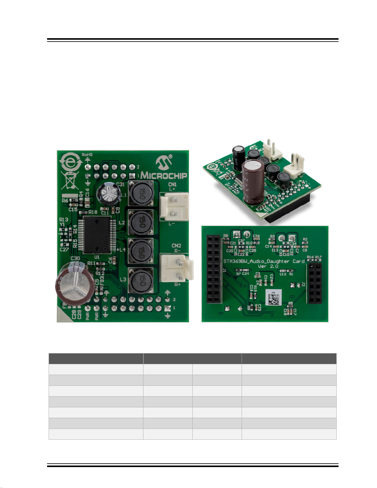
Appendix B: STA369BW Audio Daughter Board
8. Appendix B: STA369BW Audio Daughter Board
The STA369BW Audio Daughter Board is a high-performance stereo codec board, which is suitable for adding audio
input and output capabilities to the Bluetooth Audio development platforms.
The STA369BW Audio Daughter Board has the following components:
• STMicroelectronics codec (STA369BW)
• Female 20-pin dual-row header (J1)
• Female 12-pin dual-row header (J2)
• Audio out connectors (CN1 and CN2)
Figure 8-1. STA369BW Audio Daughter Board
BM83 EVB
The following table provides the pin description of Audio Daughter Board headers.
Table 8-1. 20-Pin Audio Daughter Board Header (J1) Pin Details
Pin Name Pin Number Pin Name
GND 1 2 GND
UART_RXD 3 4 UART_CTS
UART_TXD 5 6 UART_RTS
I2C_SCL 7 8 RST
I2C_SDA 9 10 I2S_RFS1
I2S_DR1 11 12 I2S_SCLK1
I2S_DT1 13 14 I2S_MCLK1
© 2019 Microchip Technology Inc.
User Guide
DS50002902A-page 55
Page 56

Appendix B: STA369BW Audio Daughter Board
...........continued
Pin Name Pin Number Pin Name
GND 15 16 GND
PWR 17 18 3V3
PWR 19 20 5V
Table 8-2. 12-Pin Audio Daughter Board Header (J2) Pin Details
Pin Name Pin Number Pin Name
NC 1 2 3V3
DSP_IRQ_N 3 4 PWRDN
NC 5 6 MUTE_N
NC 7 8 INT
NC 9 10 NC
GND 11 12 GND
BM83 EVB
© 2019 Microchip Technology Inc.
User Guide
DS50002902A-page 56
Page 57

Appendix C: Digital Microphone Daughter Bo...
9. Appendix C: Digital Microphone Daughter Board
The Digital Microphone Daughter Board has the following components:
• On-board Knowles’ Digital Microphone SPH0641LU4H-1
• Female 5-pin 1x5 header (J1) to interface to BM83 EVB (J503 and J502)
Figure 9-1. Digital Microphone Daughter Board - Top and Bottom View
BM83 EVB
The following table provides the pin description of the Digital Microphone header.
Table 9-1. Digital Microphone Headers (J1, J503, and J502) Pin Description
Pin
Number
1 VDD VDD DIGMIC VDD DIGMIC Power supply from BM83 EVB
2 CLOCK DMIC1_CLK DMIC1_CLK Clock input to the microphone from
3 GND GND GND Ground
4 DATA DMIC1_L DMIC1_R PDM output from the microphone to
5 SEL DM1 SELECT DM2 SELECT Select input for microphone
Note:
1. BM83 module supports 1 stereo Digital Microphone (left and right) terminated at J503 and J502 headers
2. The VDD power supply for Digital Microphone operation is provided over J509 header on the BM83 EVB.
3. The Select pin should not be left floating and should be connected to high or low. This is achieved by 3-pin
4. For more details on using Digital Microphone with the BM83, refer to IS208x Config UI Tool User’s Guide.
Digital
Microphone
Daughter
Board
Pin Name (J1) Pin Name (J503) Pin Name (J502)
respectively.
headers J505 and J504 on BM83 EVB.
BM83 EVB Pin Description
BM83 module
BM83 module
© 2019 Microchip Technology Inc.
User Guide
DS50002902A-page 57
Page 58

Appendix D: J-Link 6-Pin Adapter Board
10. Appendix D: J-Link 6-Pin Adapter Board
J-Link 6-Pin Adapter Board is designed to connect to its targets through a 20-pin cable, provided with the J-Link.
However, BM83 EVB uses a 6-pin connector supporting 2-wire JTAG.
Figure 10-1. J-Link 6-Pin Adapter Board
BM83 EVB
The following table provides the pin description of J-Link 6-Pin Adapter Board.
Table 10-1. J-Link 6-Pin Adapter Board Pin Description
Pin Number Pin Name on J-Link
Adapter Board
1 Reset_n Reset_n Reset
2 3V3 3V3_IO Power supply from BM83 EVB
3 GND GND Ground
4 TDI P1_2 CPU-2 Wire Debug Data
5 TCK P1_3 CPU-2 Wire Debug Clock
6 NC NC NC
Pin Name on BM83
EVB
Pin Description
© 2019 Microchip Technology Inc.
User Guide
DS50002902A-page 58
Page 59

Appendix E: Updating PIC32 MCU Parameters
11. Appendix E: Updating PIC32 MCU Parameters
Perform the following steps to load the .Hex file to the MCU:
1. Set SW200 switch to 5V_DC position.
2. Plug the 15V DC power adapter into the P200 jack for supplying power to the host MCU.
3. Connect the MPLAB ICD 3 to ICSP header J400 and PC.
Figure 11-1. ICD 3 Interface at the ICSP Header
BM83 EVB
4. Ensure that jumpers on JP400 and JP401 are mounted.
Note: Download and install the latest version of MPLAB X IDE tool, which is available at www.microchip.com/
mplab/mplab-x-ide.
5. Open the MPLAB X IPE tool.
6. Under the Device drop-down menu, select the MCU (PIC32MX450F256L) that is present on the BM83 EVB.
The red dot indicates that the selected device does not match.
© 2019 Microchip Technology Inc.
User Guide
DS50002902A-page 59
Page 60
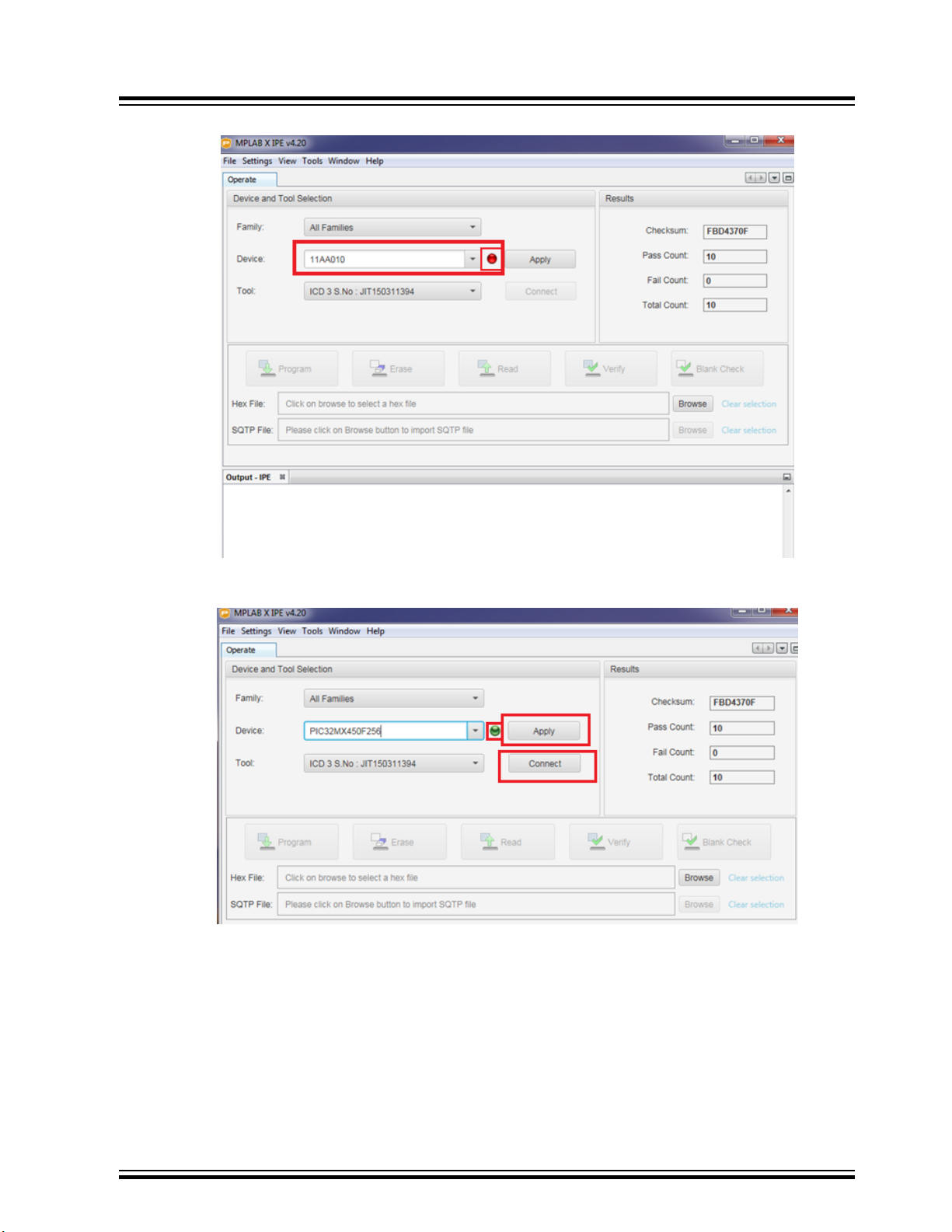
Figure 11-2. MPLAB X IPE Window
BM83 EVB
Appendix E: Updating PIC32 MCU Parameters
7. Successful device connection is indicated by a green dot. Click Apply followed by Connect.
Figure 11-3. Search for On-board Microcontroller
8. After the connection is established, click Browse and locate the MCU firmware file from the software folder.
Then click Program as shown in the following figure.
© 2019 Microchip Technology Inc.
User Guide
DS50002902A-page 60
Page 61
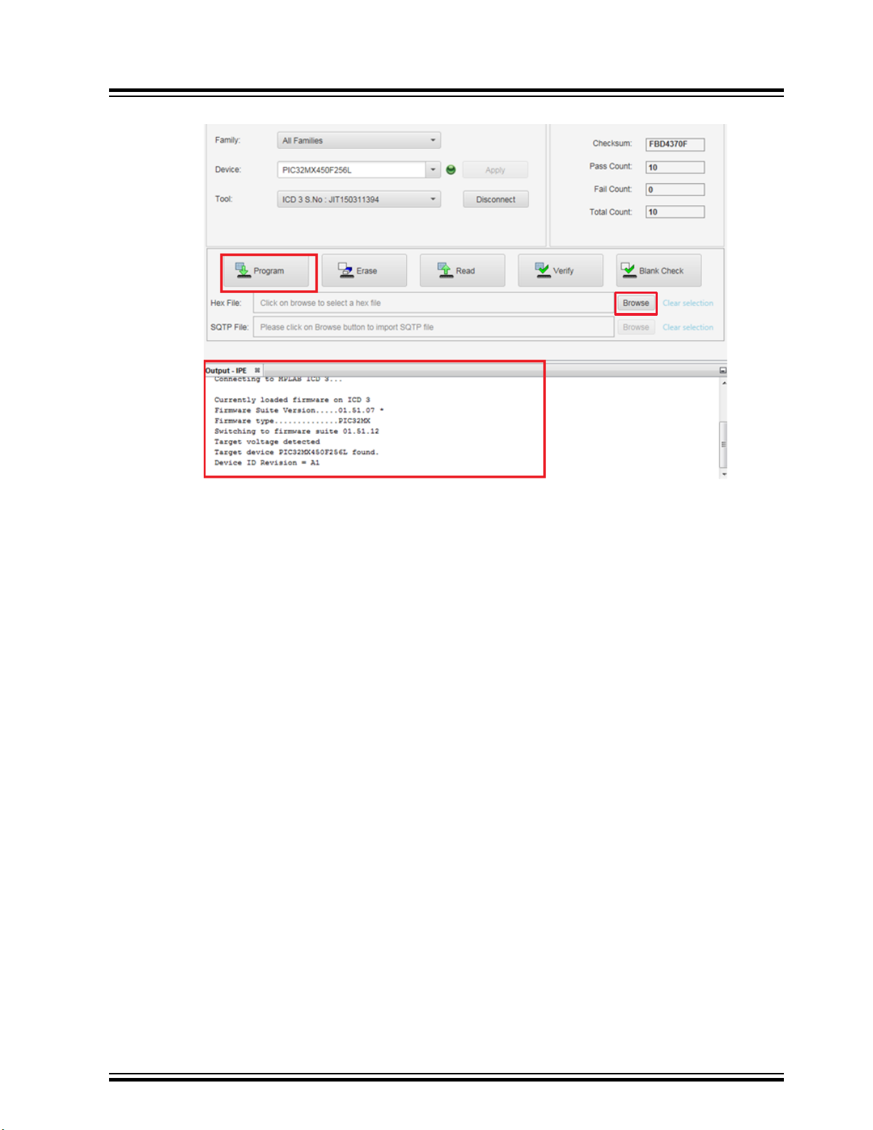
Figure 11-4. Connect and Program
BM83 EVB
Appendix E: Updating PIC32 MCU Parameters
© 2019 Microchip Technology Inc.
User Guide
DS50002902A-page 61
Page 62

Appendix E: Updating PIC32 MCU Parameters
9. After the programming is complete, observe the Output – IPE window on the console.
Note: MCU firmware version V1.4.1 is used for the demonstration.
Figure 11-5. Verify the Log
BM83 EVB
10. Remove the 15V adapter.
© 2019 Microchip Technology Inc.
User Guide
DS50002902A-page 62
Page 63

BM83 EVB
Appendix F: Hardware Setup for Application Dem...
12. Appendix F: Hardware Setup for Application Demo in Host MCU Mode
Note: The host MCU (on-board PIC32 MCU) is connected to the BM83 module over UART. The host MCU is
controlling the BM83 module and driving the I2S audio out from the BM83 to an STA369BW Audio Daughter Board.
Perform the following hardware changes for the Host MCU mode application demo:
Note: To locate these switches, jumpers, and headers on the BM83 EVB, refer to Figure 2-1 and Figure 3-2.
1. Mount a jumper on the pin2 (3V3_IO) and pin3 (VDDIO) of JP305.
2. Set the SW200 switch to 5V_DC position to enable the 5V supply to ADAP_IN.
3. Mount a jumper on the 3V3_GEN pin and 3V3_PIC pin of the JP400 to enable 3.3V to PIC.
4. Jumper settings on J402 and J403 to enable BM83 module to control DSP (audio codec):
4.1. Mount a jumper on pin1 of J402 and J403.
4.2. Mount a jumper on pin2 of J402 and J403.
4.3. Mount a jumper on pin3 of J402 and J403.
4.4. Mount a jumper on pin4 of J402 and J403.
4.5. Mount a jumper on pin5 of J402 and J403.
4.6. Mount a jumper on pin6 of J402 and J403.
4.7. Open pin7 of J402 and J403.
5. Jumper settings on J700 and J701 to enable BM83 module to control the audio control buttons:
5.1. Mount a jumper on pin1 of J700 and J701.
5.2. Mount a jumper on pin2 of J700 and J701.
5.3. Mount a jumper on pin3 of J700 and J701.
5.4. Mount a jumper on pin4 of J700 and J701.
5.5. Mount a jumper on pin5 of J700 and J701.
5.6. Mount a jumper on pin6 of J700 and J701.
5.7. Mount a jumper on pin6 of J700 and J701.
5.8. Open pin8 of J700 and J701.
6. Mount a jumper on pin2 and pin3 of JP201.
7. Set SW400 switches as follows:
7.1. RFS1_DSP to OFF position.
7.2. SCLK1 to OFF position.
7.3. DT1_DSP to OFF position.
7.4. MCLK1_DSP to OFF position.
7.5. LINE_IN_DET to ON position.
7.6. P3_2 to OFF position.
8. Set SW402 switches as follows:
8.1. MFB to OFF position.
8.2. HCI_RXD to ON position.
8.3. HCI_TXD to ON position.
8.4. RST_N to OFF position.
8.5. P0_0 to ON position.
8.6. P3_4 to ON position.
9. Set SW403 switches as follows:
9.1. P3_7 to ON position.
9.2. P2_6 to OFF position.
9.3. P2_3 to OFF position.
9.4. RFS1 to OFF position.
9.5. SCLK1 to OFF position.
9.6. DT1 to OFF position.
10. Jumper settings on J404 and J405 to connect BM83 module and STA369BW codec (ST) over I2S interface:
© 2019 Microchip Technology Inc.
User Guide
DS50002902A-page 63
Page 64
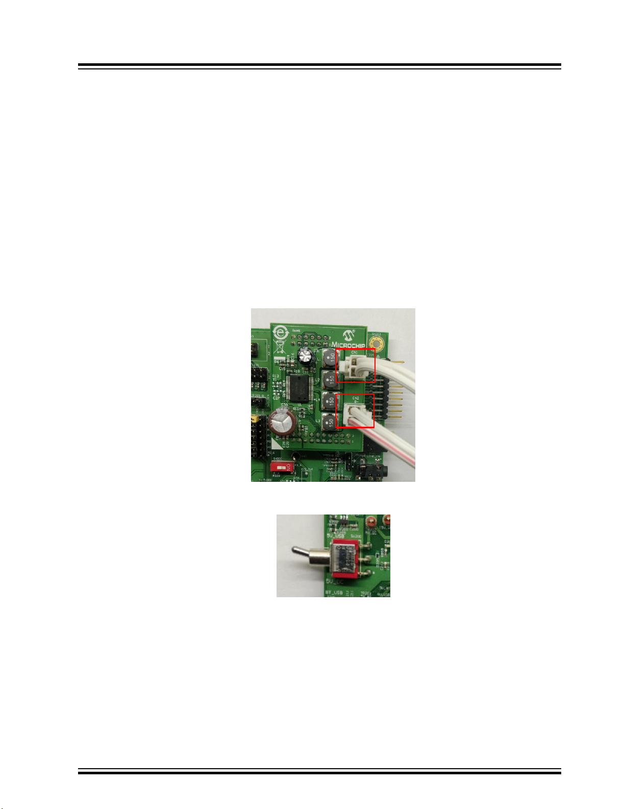
10.1. Mount a jumper on pin1 of J404 and J405.
10.2. Mount a jumper on pin2 of J404 and J405.
10.3. Mount a jumper on pin3 of J404 and J405.
10.4. Mount a jumper on pin4 of J404 and J405.
10.5. Mount a jumper on pin5 of J404 and J405.
10.6. Open pin6 of J404 and J405.
10.7. Open pin7 of J404 and J405.
11. Put the S400 switch to PIC32_MCLR position.
12. Put the SW300 switch to OFF position.
Note: In order to perform the following demo, the user must flash the Host mode firmware into the BM83 module as
well as PIC32 MCU, as illustrated in the preceding sections.
12.1 Host MCU Mode Quick Demo
Perform the following steps to stream audio using the BM83 module in Host MCU mode.
1. Connect the speakers to the STA369BW Audio Daughter Board at CN1 and CN2.
Figure 12-1. Speakers Connected to the STA369BW Audio Daughter Board
BM83 EVB
Appendix F: Hardware Setup for Application Dem...
2. The SW200 switch is set to 5V_USB position as shown in the following figure.
Figure 12-2. SW200 Switch Position
© 2019 Microchip Technology Inc.
User Guide
DS50002902A-page 64
Page 65
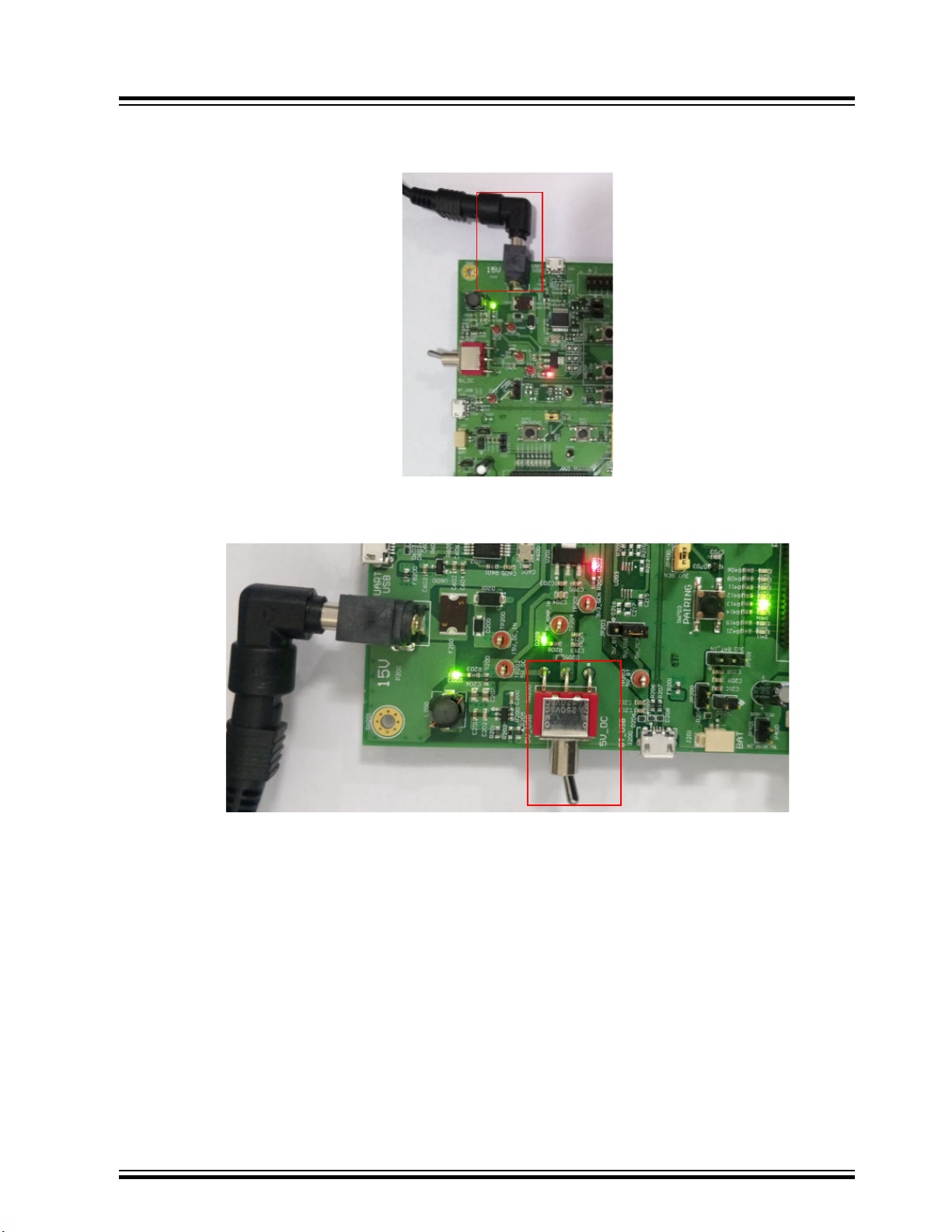
BM83 EVB
Appendix F: Hardware Setup for Application Dem...
3. Connect the 15V DC adapter at DC power jack P200. Notice that the green LED (D203) and red LED (D202)
turn ON as shown in the following figure.
Figure 12-3. 15V DC Adapter Plugged In
4. Change the SW200 switch to 5V_DC position. Notice that the green LEDs (D209 and D405) turn ON, as
shown in the following figure.
Figure 12-4. LED Indication as SW200 is Turned to 5V_DC position
5. Long press SEL button (SW711) to turn on the system. Observe the sound on the speakers and the following
LED behavior:
– Green LED (D401) turns ON
– Blue (D300) and green (D402) LEDs blink
6. Long press SEL button (SW711) to make the BM83 module discoverable to other devices. Observe the sound
on the speakers and the alternate blinking of red LED (D301) and blue LED (D300).
7. Follow the steps to pair the BM83 module with a smartphone:
7.1. Turn on the smartphone's Bluetooth to scan for the available devices.
7.2. Select the module device name "BM83" from the scan results. Pair and then connect the device.
7.3. On successful pairing, see the device name with status as Connected.
Note: This demonstration uses the EA1 demo version of the firmware.
© 2019 Microchip Technology Inc.
User Guide
DS50002902A-page 65
Page 66
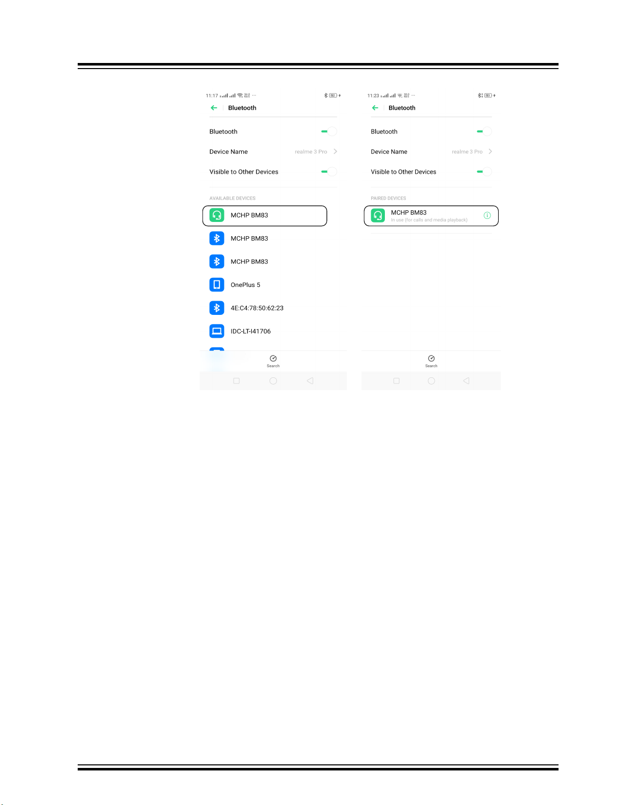
Appendix F: Hardware Setup for Application Dem...
Figure 12-5. Pairing and Connection
BM83 EVB
7.4. Stream the audio from the smartphone to the BM83 over Bluetooth connection, and listen to it over
the speakers.
8. Control the audio with the following buttons:
8.1. Press VOL_UP button(SW702) to increase the volume.
8.2. Press VOL_DN button (SW705) to reduce the volume.
8.3. Press Pause button (SW704) to pause the audio.
8.4. Press Play button (SW704) to play the audio.
8.5. Press FWD button (SW707) to jump to next audio file.
8.6. Press REV button (SW708) to jump to previous audio file.
8.7. Press SEL button (SW711) to turn OFF the system.
© 2019 Microchip Technology Inc.
User Guide
DS50002902A-page 66
Page 67

BM83 EVB
Appendix G: Hardware Setup for Application Dem...
13. Appendix G: Hardware Setup for Application Demo in Embedded Mode
Note: In this mode of operation, the BM83 module is driving the I2S audio out to the STA369BW Audio Daughter
Board. The BM83 module is connected to the external codec over I2S and I2C.
Perform the following hardware changes for the Embedded mode application demo.
Note: To locate these switches, jumpers, and headers on the BM83 EVB, refer to Figure 2-1 and Figure 3-2.
1. Mount a jumper on the 3V3_IO pin and VDDIO pins of the JP305 pin 2 and pin3.
2. Put the SW200 switch to 5V_DC position to enable the 5V supply to ADAP_IN.
3. Jumper settings on J401 and J402 enable BM83 module to control the STA369BW Audio Daughter Board:
3.1. Mount a jumper on pin1 of J401 and J402.
3.2. Open pin2 of J401 and J402.
3.3. Open pin3 of J401 and J402.
3.4. Mount a jumper on pin4 of J401 and J402.
3.5. Mount a jumper on pin5 of J401 and J402.
3.6. Open pin6 of J401 and J402.
3.7. Mount a jumper on pin7 of J401 and J402.
4. Jumper settings on J701 and J702 to enable BM83 module to control the audio control buttons:
4.1. Mount a jumper on pin1 of J701 and J702.
4.2. Mount a jumper on pin2 of J701 and J702.
4.3. Mount a jumper on pin3 of J701 and J702.
4.4. Mount a jumper on pin4 of J701 and J702.
4.5. Mount a jumper on pin5 of J701 and J702.
4.6. Open pin6 of J701 and J702.
4.7. Mount a jumper on pin7 of J701 and J702.
4.8. Open pin8 of J701 and J702.
5. Mount jumper on the JP201 pin2 and pin3.
6. Set SW400 switches as follows:
6.1. RFS1_DSP to OFF position.
6.2. SCLK1 to OFF position.
6.3. DT1_DSP to OFF position.
6.4. MCLK1_DSP to OFF position.
6.5. LINE_IN_DET to OFF position.
6.6. P3_2 to ON position.
7. Set SW402 switches as follows:
7.1. MFB to OFF position.
7.2. HCI_RXD to OFF position.
7.3. HCI_TXD to OFF position.
7.4. RST_N to OFF position.
7.5. P0_0 to OFF position.
7.6. P3_4 to OFF position.
8. Set SW403 switches as follows:
8.1. P3_7 to OFF position.
8.2. P2_6 to OFF position.
8.3. P2_3 to OFF position.
8.4. RFS1 to OFF position.
8.5. SCLK1 to OFF position.
8.6. DT1 to OFF position.
© 2019 Microchip Technology Inc.
User Guide
DS50002902A-page 67
Page 68

BM83 EVB
Appendix G: Hardware Setup for Application Dem...
9. Jumper settings on J404 and J405 to connect BM83 module I2S with STA369BW Audio Daughter Board I2S:
9.1. Mount a jumper on pin1 of J404 and J405.
9.2. Mount a jumper on pin2 of J404 and J405.
9.3. Mount a jumper on pin3 of J404 and J405.
9.4. Mount a jumper on pin4 of J404 and J405.
9.5. Mount a jumper on pin5 of J404 and J405.
9.6. Open pin6 of J404 and J405.
9.7. Open pin7 of J404 and J405.
10. Put the SW300 switch to OFF position.
11. By default, the board is configured with hardware (HW) I2C settings. For more details on the software (SW)
I2C settings, refer to I2C Interface section in the IS2083 SDK User’s Guide (DS50002894).
12. Mount a jumper on pin2 and pin3 of the JP203.
With the above settings, the user can plug in the 15V DC adapter and perform the application demo in Embedded
mode with the appropriate firmware image. This firmware image for the Embedded mode is available at
www.microchip.com/BM83.
© 2019 Microchip Technology Inc.
User Guide
DS50002902A-page 68
Page 69
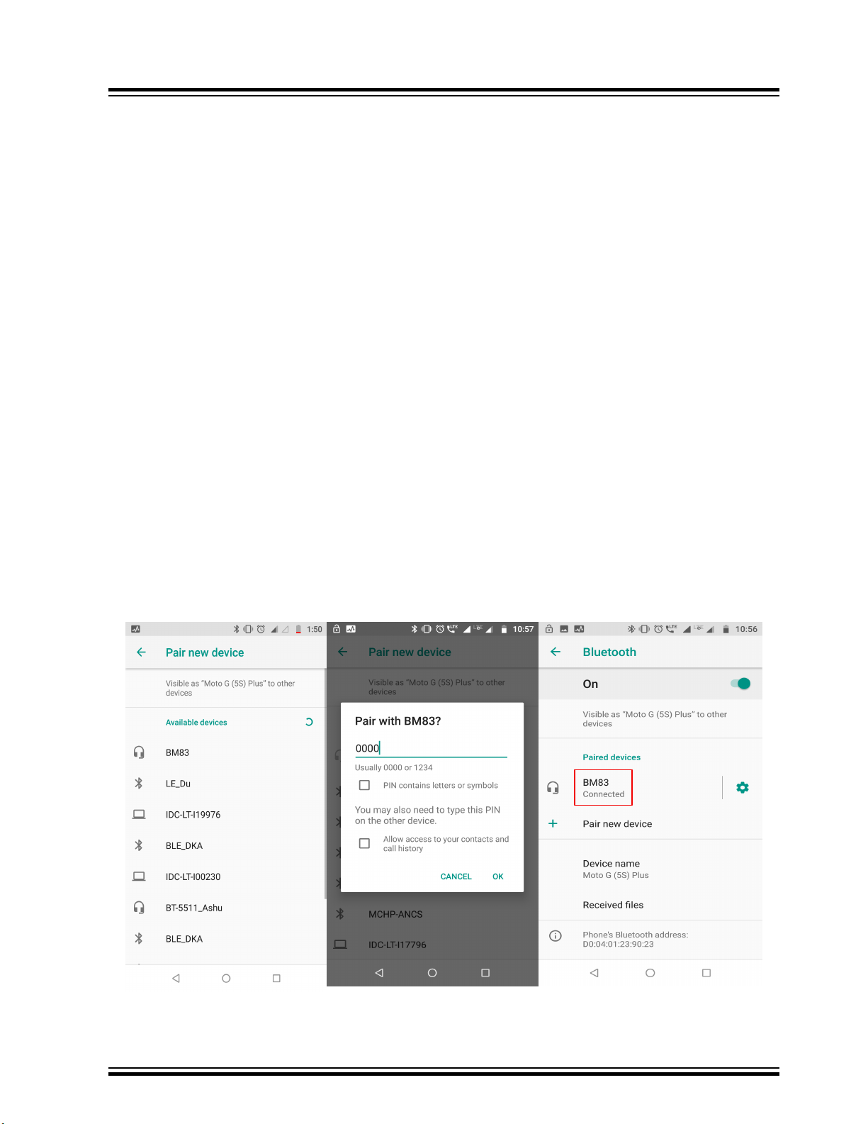
BM83 EVB
Appendix H: Bluetooth Audio Demonstration in ...
14. Appendix H: Bluetooth Audio Demonstration in Embedded Mode with Internal Codec
Note:
1. In this mode of operation, the BM83 module uses internal codec to drive the audio.
2. Do not connect 15V adapter at DC power jack P200.
3. Use the internal codec config file for this demo, for more details, refer to 6.1 Config Tool Setup.
In this demonstration, the user can stream audio on the BM83 EVB using a smartphone. Perform the following
hardware settings on the BM83 EVB for Embedded mode with internal codec audio demo after updating the
firmware:
1. Turn OFF the SW300 switch.
2. Mount a jumper at 5V_ADAP_IN and ADAP_IN of JP304.
3. Ensure to mount JP501 and JP503 (stereo out). Connect headphones or a speaker at stereo jack P503.
4. Set the SW200 switch to 5V_USB.
5. Plug the USB cable at J600. Observe that the Red LED (D600) and the Green LED (D209) turn ON.
Note: Red LED (D300) and Blue LED (D301) do not glow in this case.
6. Long press MFB button (SW701) to turn ON the system and keep pressing the MFB button to enter into
Pairing mode. Once the system is turned ON, the Red LED (D301) and the Blue LED (D300) blink alternately
to indicate that the device has entered into Pairing mode.
7. The following steps help in pairing between BM83 module and a smartphone:
7.1. Turn ON the smartphone's Bluetooth to scan for the discoverable devices.
7.2. Select the module device name “BM83” from the scan results.
7.3. Enter 0000 as passcode to pair the smartphone with the BM83 module. The passcode is not required
if simple pairing is enabled in the Config Tool.
The smartphone displays “Connected” upon successful pairing as highlighted in the following figure. The audio can
be listened over the headphones.
Figure 14-1. Pairing BM83 with Smartphone
© 2019 Microchip Technology Inc.
User Guide
DS50002902A-page 69
Page 70

15. Document Revision History
Revision Date Section Description
A 07/2019 Document Initial Revision
BM83 EVB
Document Revision History
© 2019 Microchip Technology Inc.
User Guide
DS50002902A-page 70
Page 71

BM83 EVB
The Microchip Website
Microchip provides online support via our website at http://www.microchip.com/. This website is used to make files
and information easily available to customers. Some of the content available includes:
• Product Support – Data sheets and errata, application notes and sample programs, design resources, user’s
guides and hardware support documents, latest software releases and archived software
• General Technical Support – Frequently Asked Questions (FAQs), technical support requests, online
discussion groups, Microchip design partner program member listing
• Business of Microchip – Product selector and ordering guides, latest Microchip press releases, listing of
seminars and events, listings of Microchip sales offices, distributors and factory representatives
Product Change Notification Service
Microchip’s product change notification service helps keep customers current on Microchip products. Subscribers will
receive email notification whenever there are changes, updates, revisions or errata related to a specified product
family or development tool of interest.
To register, go to http://www.microchip.com/pcn and follow the registration instructions.
Customer Support
Users of Microchip products can receive assistance through several channels:
• Distributor or Representative
• Local Sales Office
• Embedded Solutions Engineer (ESE)
• Technical Support
Customers should contact their distributor, representative or ESE for support. Local sales offices are also available to
help customers. A listing of sales offices and locations is included in this document.
Technical support is available through the website at: http://www.microchip.com/support
Microchip Devices Code Protection Feature
Note the following details of the code protection feature on Microchip devices:
• Microchip products meet the specification contained in their particular Microchip Data Sheet.
• Microchip believes that its family of products is one of the most secure families of its kind on the market today,
when used in the intended manner and under normal conditions.
• There are dishonest and possibly illegal methods used to breach the code protection feature. All of these
methods, to our knowledge, require using the Microchip products in a manner outside the operating
specifications contained in Microchip’s Data Sheets. Most likely, the person doing so is engaged in theft of
intellectual property.
• Microchip is willing to work with the customer who is concerned about the integrity of their code.
• Neither Microchip nor any other semiconductor manufacturer can guarantee the security of their code. Code
protection does not mean that we are guaranteeing the product as “unbreakable.”
Code protection is constantly evolving. We at Microchip are committed to continuously improving the code protection
features of our products. Attempts to break Microchip’s code protection feature may be a violation of the Digital
Millennium Copyright Act. If such acts allow unauthorized access to your software or other copyrighted work, you
may have a right to sue for relief under that Act.
Legal Notice
Information contained in this publication regarding device applications and the like is provided only for your
convenience and may be superseded by updates. It is your responsibility to ensure that your application meets with
© 2019 Microchip Technology Inc.
User Guide
DS50002902A-page 71
Page 72

BM83 EVB
your specifications. MICROCHIP MAKES NO REPRESENTATIONS OR WARRANTIES OF ANY KIND WHETHER
EXPRESS OR IMPLIED, WRITTEN OR ORAL, STATUTORY OR OTHERWISE, RELATED TO THE INFORMATION,
INCLUDING BUT NOT LIMITED TO ITS CONDITION, QUALITY, PERFORMANCE, MERCHANTABILITY OR
FITNESS FOR PURPOSE. Microchip disclaims all liability arising from this information and its use. Use of Microchip
devices in life support and/or safety applications is entirely at the buyer’s risk, and the buyer agrees to defend,
indemnify and hold harmless Microchip from any and all damages, claims, suits, or expenses resulting from such
use. No licenses are conveyed, implicitly or otherwise, under any Microchip intellectual property rights unless
otherwise stated.
Trademarks
The Microchip name and logo, the Microchip logo, Adaptec, AnyRate, AVR, AVR logo, AVR Freaks, BesTime,
BitCloud, chipKIT, chipKIT logo, CryptoMemory, CryptoRF, dsPIC, FlashFlex, flexPWR, HELDO, IGLOO, JukeBlox,
KeeLoq, Kleer, LANCheck, LinkMD, maXStylus, maXTouch, MediaLB, megaAVR, Microsemi, Microsemi logo, MOST,
MOST logo, MPLAB, OptoLyzer, PackeTime, PIC, picoPower, PICSTART, PIC32 logo, PolarFire, Prochip Designer,
QTouch, SAM-BA, SenGenuity, SpyNIC, SST, SST Logo, SuperFlash, Symmetricom, SyncServer, Tachyon,
TempTrackr, TimeSource, tinyAVR, UNI/O, Vectron, and XMEGA are registered trademarks of Microchip Technology
Incorporated in the U.S.A. and other countries.
APT, ClockWorks, The Embedded Control Solutions Company, EtherSynch, FlashTec, Hyper Speed Control,
HyperLight Load, IntelliMOS, Libero, motorBench, mTouch, Powermite 3, Precision Edge, ProASIC, ProASIC Plus,
ProASIC Plus logo, Quiet-Wire, SmartFusion, SyncWorld, Temux, TimeCesium, TimeHub, TimePictra, TimeProvider,
Vite, WinPath, and ZL are registered trademarks of Microchip Technology Incorporated in the U.S.A.
Adjacent Key Suppression, AKS, Analog-for-the-Digital Age, Any Capacitor, AnyIn, AnyOut, BlueSky, BodyCom,
CodeGuard, CryptoAuthentication, CryptoAutomotive, CryptoCompanion, CryptoController, dsPICDEM,
dsPICDEM.net, Dynamic Average Matching, DAM, ECAN, EtherGREEN, In-Circuit Serial Programming, ICSP,
INICnet, Inter-Chip Connectivity, JitterBlocker, KleerNet, KleerNet logo, memBrain, Mindi, MiWi, MPASM, MPF,
MPLAB Certified logo, MPLIB, MPLINK, MultiTRAK, NetDetach, Omniscient Code Generation, PICDEM,
PICDEM.net, PICkit, PICtail, PowerSmart, PureSilicon, QMatrix, REAL ICE, Ripple Blocker, SAM-ICE, Serial Quad
I/O, SMART-I.S., SQI, SuperSwitcher, SuperSwitcher II, Total Endurance, TSHARC, USBCheck, VariSense,
ViewSpan, WiperLock, Wireless DNA, and ZENA are trademarks of Microchip Technology Incorporated in the U.S.A.
and other countries.
SQTP is a service mark of Microchip Technology Incorporated in the U.S.A.
The Adaptec logo, Frequency on Demand, Silicon Storage Technology, and Symmcom are registered trademarks of
Microchip Technology Inc. in other countries.
GestIC is a registered trademark of Microchip Technology Germany II GmbH & Co. KG, a subsidiary of Microchip
Technology Inc., in other countries.
All other trademarks mentioned herein are property of their respective companies.
©
2019, Microchip Technology Incorporated, Printed in the U.S.A., All Rights Reserved.
ISBN: 978-1-5224-4808-2
Quality Management System
For information regarding Microchip’s Quality Management Systems, please visit http://www.microchip.com/quality.
© 2019 Microchip Technology Inc.
User Guide
DS50002902A-page 72
Page 73

Worldwide Sales and Service
AMERICAS ASIA/PACIFIC ASIA/PACIFIC EUROPE
Corporate Office
2355 West Chandler Blvd.
Chandler, AZ 85224-6199
Tel: 480-792-7200
Fax: 480-792-7277
Technical Support:
http://www.microchip.com/support
Web Address:
http://www.microchip.com
Atlanta
Duluth, GA
Tel: 678-957-9614
Fax: 678-957-1455
Austin, TX
Tel: 512-257-3370
Boston
Westborough, MA
Tel: 774-760-0087
Fax: 774-760-0088
Chicago
Itasca, IL
Tel: 630-285-0071
Fax: 630-285-0075
Dallas
Addison, TX
Tel: 972-818-7423
Fax: 972-818-2924
Detroit
Novi, MI
Tel: 248-848-4000
Houston, TX
Tel: 281-894-5983
Indianapolis
Noblesville, IN
Tel: 317-773-8323
Fax: 317-773-5453
Tel: 317-536-2380
Los Angeles
Mission Viejo, CA
Tel: 949-462-9523
Fax: 949-462-9608
Tel: 951-273-7800
Raleigh, NC
Tel: 919-844-7510
New York, NY
Tel: 631-435-6000
San Jose, CA
Tel: 408-735-9110
Tel: 408-436-4270
Canada - Toronto
Tel: 905-695-1980
Fax: 905-695-2078
Australia - Sydney
Tel: 61-2-9868-6733
China - Beijing
Tel: 86-10-8569-7000
China - Chengdu
Tel: 86-28-8665-5511
China - Chongqing
Tel: 86-23-8980-9588
China - Dongguan
Tel: 86-769-8702-9880
China - Guangzhou
Tel: 86-20-8755-8029
China - Hangzhou
Tel: 86-571-8792-8115
China - Hong Kong SAR
Tel: 852-2943-5100
China - Nanjing
Tel: 86-25-8473-2460
China - Qingdao
Tel: 86-532-8502-7355
China - Shanghai
Tel: 86-21-3326-8000
China - Shenyang
Tel: 86-24-2334-2829
China - Shenzhen
Tel: 86-755-8864-2200
China - Suzhou
Tel: 86-186-6233-1526
China - Wuhan
Tel: 86-27-5980-5300
China - Xian
Tel: 86-29-8833-7252
China - Xiamen
Tel: 86-592-2388138
China - Zhuhai
Tel: 86-756-3210040
India - Bangalore
Tel: 91-80-3090-4444
India - New Delhi
Tel: 91-11-4160-8631
India - Pune
Tel: 91-20-4121-0141
Japan - Osaka
Tel: 81-6-6152-7160
Japan - Tokyo
Tel: 81-3-6880- 3770
Korea - Daegu
Tel: 82-53-744-4301
Korea - Seoul
Tel: 82-2-554-7200
Malaysia - Kuala Lumpur
Tel: 60-3-7651-7906
Malaysia - Penang
Tel: 60-4-227-8870
Philippines - Manila
Tel: 63-2-634-9065
Singapore
Tel: 65-6334-8870
Taiwan - Hsin Chu
Tel: 886-3-577-8366
Taiwan - Kaohsiung
Tel: 886-7-213-7830
Taiwan - Taipei
Tel: 886-2-2508-8600
Thailand - Bangkok
Tel: 66-2-694-1351
Vietnam - Ho Chi Minh
Tel: 84-28-5448-2100
Austria - Wels
Tel: 43-7242-2244-39
Fax: 43-7242-2244-393
Denmark - Copenhagen
Tel: 45-4450-2828
Fax: 45-4485-2829
Finland - Espoo
Tel: 358-9-4520-820
France - Paris
Tel: 33-1-69-53-63-20
Fax: 33-1-69-30-90-79
Germany - Garching
Tel: 49-8931-9700
Germany - Haan
Tel: 49-2129-3766400
Germany - Heilbronn
Tel: 49-7131-72400
Germany - Karlsruhe
Tel: 49-721-625370
Germany - Munich
Tel: 49-89-627-144-0
Fax: 49-89-627-144-44
Germany - Rosenheim
Tel: 49-8031-354-560
Israel - Ra’anana
Tel: 972-9-744-7705
Italy - Milan
Tel: 39-0331-742611
Fax: 39-0331-466781
Italy - Padova
Tel: 39-049-7625286
Netherlands - Drunen
Tel: 31-416-690399
Fax: 31-416-690340
Norway - Trondheim
Tel: 47-72884388
Poland - Warsaw
Tel: 48-22-3325737
Romania - Bucharest
Tel: 40-21-407-87-50
Spain - Madrid
Tel: 34-91-708-08-90
Fax: 34-91-708-08-91
Sweden - Gothenberg
Tel: 46-31-704-60-40
Sweden - Stockholm
Tel: 46-8-5090-4654
UK - Wokingham
Tel: 44-118-921-5800
Fax: 44-118-921-5820
© 2019 Microchip Technology Inc.
User Guide
DS50002902A-page 73
 Loading...