

Page 1

Introduction
BM71-XPro
BM70/71 XPro User's Guide
The BM71-XPro board is a hardware platform designed to evaluate and test the capabilities of the BM71 Bluetooth
RF module. The BM71-XPro board provides multiple options for rapid prototyping and developing applications. The
board is supported by Atmel Studio, an integrated development platform, which provides predefined applications and
examples.
®
Features
• USB-UART Bridge (MCP2200) for Host PC Operation
• On Board 3.3V LDO for Power Regulation
• On Board SPI Flash for Storing Firmware Images (DFU OTA)
• Test Point for GPIO Pin (P1_3)
• Reset Push Button
• DIP Switch to Control:
– BM71 operation mode
– LED
– GPIO pin
• Passive RC Filters for PWM and ADC Inputs
• Atmel Studio (ASF3), to Provide Predefined Application Examples
• XPRO Extension Header
• Header Pins for Current Measurement
• Two Power Sources:
– Micro USB
– XPRO Connector
© 2019 Microchip Technology Inc.
DS50002891A-page 1
Page 2

BM71-XPro
Table of Contents
Introduction.....................................................................................................................................................1
Features......................................................................................................................................................... 1
1. Kit Contents.............................................................................................................................................3
1.1. Reference Documentation............................................................................................................3
2. Hardware Features................................................................................................................................. 4
2.1. Power Supply............................................................................................................................... 4
2.2. USB-UART Bridge........................................................................................................................4
2.3. XPRO Connector..........................................................................................................................4
2.4. DIP Switch....................................................................................................................................5
2.5. Reset Switch................................................................................................................................ 5
2.6. Current Measurement Header......................................................................................................5
2.7. On-board SPI Flash......................................................................................................................5
3. Module Configuration.............................................................................................................................. 7
3.1. Connecting the BM71 XPRO to MBD App in Auto Mode.............................................................7
3.2. Configuring the BM71 Module to Operate in Manual Mode (Host PC)...................................... 10
3.3. Connecting the BM71-XPro to MBD App in Manual Mode (Host PC)........................................14
3.4. Using the BM70/71 MCU drivers................................................................................................23
4. Appendix A. Updating the BM71 Module Firmware.............................................................................. 27
5. Appendix B. Schematics and Bill of Materials.......................................................................................28
6. Agency Certification.............................................................................................................................. 33
6.1. Europe........................................................................................................................................33
7. Document Revision History...................................................................................................................34
The Microchip Website.................................................................................................................................35
Product Change Notification Service............................................................................................................35
Customer Support........................................................................................................................................ 35
Microchip Devices Code Protection Feature................................................................................................ 35
Legal Notice................................................................................................................................................. 35
Trademarks.................................................................................................................................................. 36
Quality Management System....................................................................................................................... 36
Worldwide Sales and Service.......................................................................................................................37
© 2019 Microchip Technology Inc.
DS50002891A-page 2
Page 3
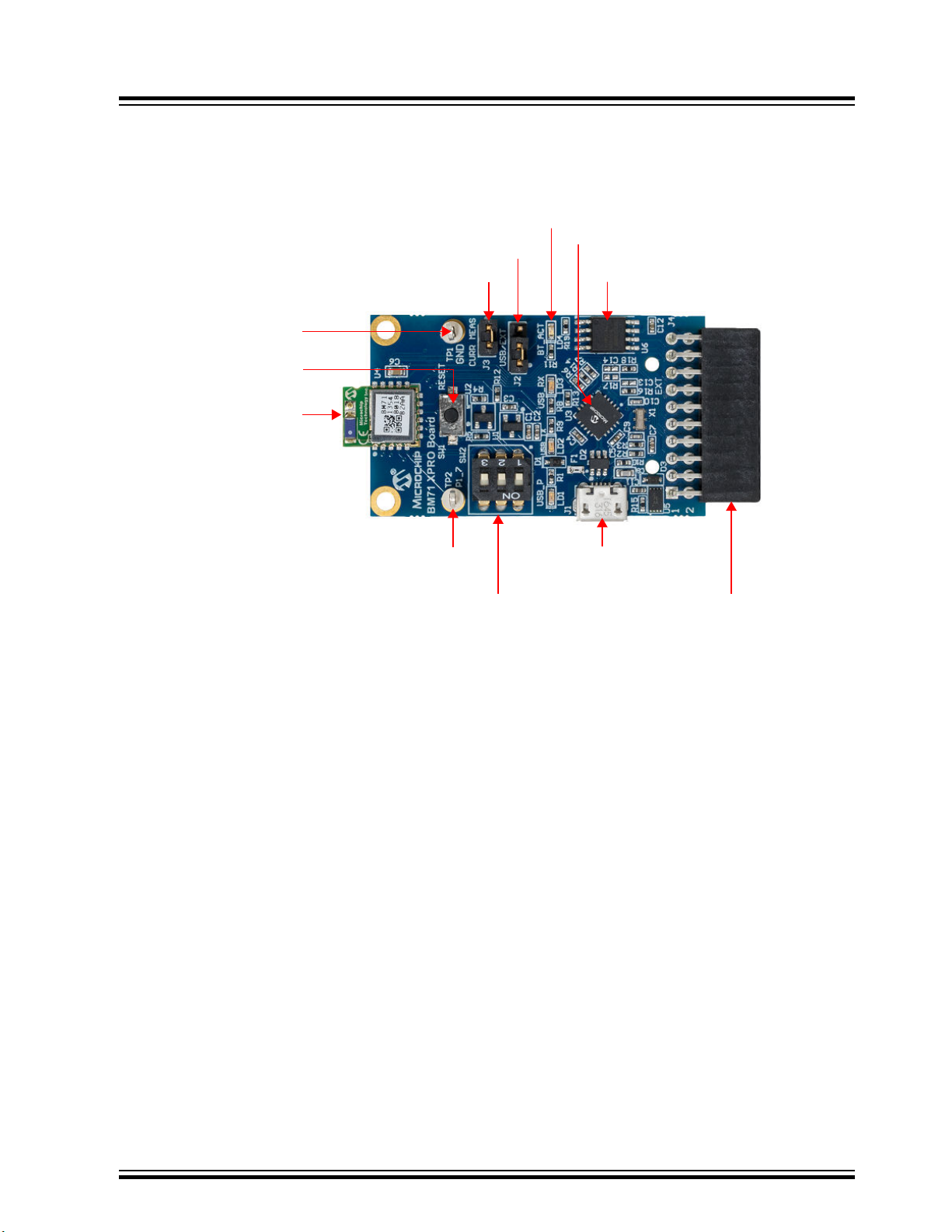
1. Kit Contents
BM71 Module
Reset Switch
Ground Test Point
Current Measurement Header
Power Supply Selection Header
BM71 LED
USB-UART Bridge (MCP200)
On board SPI Flash
XPRO Connector
Mini USB Connector
DIP Switch
GPIO P1_7 Test Point
The following figure shows the layout of the BM71-XPro board and illustrates the components available in the board:
Figure 1-1. BM71-XPro Board
BM71-XPro
Kit Contents
1.1 Reference Documentation
Microchip offers several smartphone applications, available for free in both the App Store (iPhone®) and Google
Play™ store (Android™), to evaluate the BM71 module. For details on the currently available apps, please refer to the
BM71 XPro webpage.
For further information, refer to the following:
• BM70/71 Bluetooth® Low Energy (BLE) Module Data Sheet (DS60001372)
• BM70/71 Bluetooth® Low Energy Module User’s Guide (DS50002542).
© 2019 Microchip Technology Inc.
DS50002891A-page 3
Page 4

2. Hardware Features
A description of some of the key features in the BM71-XPro board is provided below. Refer to Figure 1-1 for details of
the kit contents.
2.1 Power Supply
Power the BM71-XPro kit using any of the power sources listed below:
• Micro USB port (J1)
• XPro Connector
Use the J2 header for selecting between these power supply options using a jumper. The green LED (LD1) indicates
that the board is powered by a micro-USB. The micro-USB has ESD and overcurrent protection, and the input to the
module is controlled via an LDO (U1). The BM71-XPro board can be operated in a standalone mode when powered
via the micro-USB.
2.2 USB-UART Bridge
The MCP2200 in the BM71-XPro board provides the option to evaluate the BM71 module in Standalone mode. By
default (out of the box), the BM71 module is set to operate in Auto mode. So, the module, once powered via the
micro-USB, will be able to connect to a peer Bluetooth Low Energy device and open a data pipe for data transfer.
Refer to 3.1 Connecting the BM71 XPRO to MBD App in Auto Mode for details. Apart from powering the board, the
micro-USB port can also be used to evaluate and test the module via a host PC. Microchip provides emulation tools,
such as a UI tool, auto pattern tool, and manual tool (refer to BM71 webpage for details) to evaluate the BM71 via a
host PC. The BM71 module can be set to operate in Manual mode for complete control or in Auto mode for a simple
data pipe application.
BM71-XPro
Hardware Features
2.3 XPRO Connector
The BM71-XPro board has an Xplained Pro (XPRO) header to offer connectivity and control from a host MCU. The
header is based on a standard extension header and its pin details are specified in the following table. The headers
have a pitch of 2.54 mm. For details on the operating the BM71-XPro via a host MCU Xplained Pro board, refer to
3.3 Connecting the BM71-XPro to MBD App in Manual Mode (Host PC).
Table 2-1. Extension Header (J1) Pin Description
Pin# Pin name Description
1 ID ID Chip communication
2 GND Ground
3 ADC1 Connected to pin P2_0 to set system configuration
4 ADC2 Connect to Reset pin of BM71
5 RTS/GPIO Connected to host MCU RTS
6 CTS/GPIO Connected to host MCU CTS
7 PWM+ PWM pin (+) of host MCU
8 PWM- PWM pin (-) of host MCU
9 GPIO Connected to GPIO pin P2_7 (TX_Ind)
10 GPIO Connected to GPIO Pin P1_6 (RX_Ind)
© 2019 Microchip Technology Inc.
DS50002891A-page 4
Page 5

...........continued
Pin# Pin name Description
11 I2C SDA
12 I2CSCL
13 Host MCU Rx Connects to BM71 Tx pin
14 Host MCU Tx Connects to BM71 Rx pin
15 SPI SS SPI SS pin of Flash memory
16 SPI MOSI SPI MOSI pin of Flash memory
17 SPI MISO SPI MISO pin of Flash memory
18 SPI SCK SPI SCK pin of Flash memory
19 GND Ground
20 Vdd Power supply
BM71-XPro
Hardware Features
2.4 DIP Switch
The DIP switch has three switches which provide the functions described in the following table.
Table 2-2. DIP Switch Functions
Switch# Function
1 Manually set the BM71 system configuration. Connected to pin P2_0.
• ON: Memory Programming mode
• OFF: Application mode
2 Turn the Blue LED (LD4) ON/OFF
3 Control the GPIO pin P1_3
2.5 Reset Switch
The Reset push button is connected to the BM71 module reset line. When the Reset button is pressed, it drives the
reset line to ground. The BM71-XPro board has an on-board voltage detected reset IC (MCP112) connected to the
Reset pin of the BM71.
2.6 Current Measurement Header
A J3 header can be used for current measurement.. All power to the BM71-XPro is routed through these header pins.
To measure the power consumption of the module, remove the jumper and replace it with an ammeter. To make sure
only the power consumption of the BM71 module is measured, turn off the blue LED using switch #2 of the DIP
switch.
2.7 On-board SPI Flash
An SST25VF080B SPI Flash memory is included in the BM71-XPro board for nonvolatile firmware storage. This can
be used to update the device firmware for the BM71 or the host MCU.
© 2019 Microchip Technology Inc.
DS50002891A-page 5
Page 6

BM71-XPro
Hardware Features
Note: BM71 Xplained Pro board is intended for use for development, demonstration or evaluation purposes only. It
is not a finished appliance, nor is it intended for incorporation into or reference design for finished appliances that are
made commercially available.
Every effort has been made to minimize electromagnetic emissions from the product. However, under certain
conditions, the system (this product connected to a host application circuit via Xplained Pro extension header for
communicating with External SPI Flash) may emit individual electromagnetic component frequencies which exceed
the maximum values allowed by the standards. The frequency and magnitude of the emissions will be determined by
several factors, including layout and routing of the application with which the product is used. The recommendation is
to add external series resistors on the Xplained Pro Extension Header SPI signals to the External SPI Flash if the
product causes emissions above the permissible limits of the standard. For reference for the BM71 module
placement and layout guidelines please refer the BM71 Module datasheet.
© 2019 Microchip Technology Inc.
DS50002891A-page 6
Page 7

3. Module Configuration
The BM70/71 module supports following modes, which affect the overall Bluetooth Low Energy and hardware
behavior:
• Auto operation configuration or Auto mode: By default, the BM70/71 module is set to operate in the Auto
mode. The Auto mode restricts the available Bluetooth Low Energy operations by only allowing the Bluetooth
Low Energy peripheral to act as a raw data pipe. This is compatible with hosts who only require the BM70/71
module to act as a virtual UART cable between the host and the remote peer device.
• Manual operation configuration or Manual mode: Manual operation provides the host MCU a lot more control
and functional options over the BM71 Bluetooth Low Energy protocol and operation in comparison to the Auto
Operation mode. This configuration is used by a host MCU to leverage the flexibility and feature set offered by
both the Bluetooth Low Energy protocol and the BM71 module (for example: private services and
characteristics).
Note: For more details, refer to the Section 1.1 Operation Overview in the BM70/71 Bluetooth Low Energy Module
User’s Guide (DS50002542).
The simplest method to start evaluating the BM71 is to connect it to a host PC that supports USB CDC virtual COM
(serial) ports and operates in Auto mode. In this mode, the user can directly connect to the BM71 from a peer device
(phone app) and open a raw data pipe. Refer to 3.1 Connecting the BM71 XPRO to MBD App in Auto Mode for
connection procedure. See 3.2 Configuring the BM71 Module to Operate in Manual Mode (Host PC) and 3.3
Connecting the BM71-XPro to MBD App in Manual Mode (Host PC) for an example of Manual mode of operation.
BM71-XPro
Module Configuration
3.1 Connecting the BM71 XPRO to MBD App in Auto Mode
Hardware/Software required:
• BM71-XPro board; Mini-USB cable.
• A PC host supporting USB CDC virtual serial port. BM71-XPro board uses MCP2200 USB to UART bridge. The
drivers can be downloaded from http://www.microchip.com/MCP2200.
• Terminal Emulator application. TeraTerm or CoolTerm is recommended.
• Microchip MBD app for iOS or Android. Available in:
– App Store (iOS) for iPhones.
– Google Play Store for Android phones.
By default, the BM71 module is set to operate in Auto mode. For details on the Auto mode of operation on the BM71
module, refer to section 1.1.2.1 in the BM70/71 User’s Guide (DS50002542).
The procedure to connect the BM71-XPro board to a peer device (phone/table) via host PC is given below:
1. Ensure that the BM71-XPro board is configured as follows:
1.1. Jumper on the J2 header is closed to select USB power option.
1.2. The current measurement jumper on J3 is present.
1.3. Switch 1 (system configuration) on the DIP switch is set to OFF.
1.4. Switch 2 (blue LED) on the DIP switch is set to ON.
2. Connect the BM71-XPro board to a host PC using the mini-USB cable. Ensure that green LED (LD1) is solid
ON indicating USB power.
3. Connect BM71-XPro to a PC host using micro-USB cable.
3.1. Verify the virtual COM port is enumerated on a host PC. If the COM port does not enumerate, the
MCP2200 drivers may be missing from the host PC. If needed, the drivers can be downloaded from
the www.microchip.com/MCP2200 webpage.
3.2. Press the Reset button (SW1) and verify that the blue LED (LD4) is flashing intermittently.
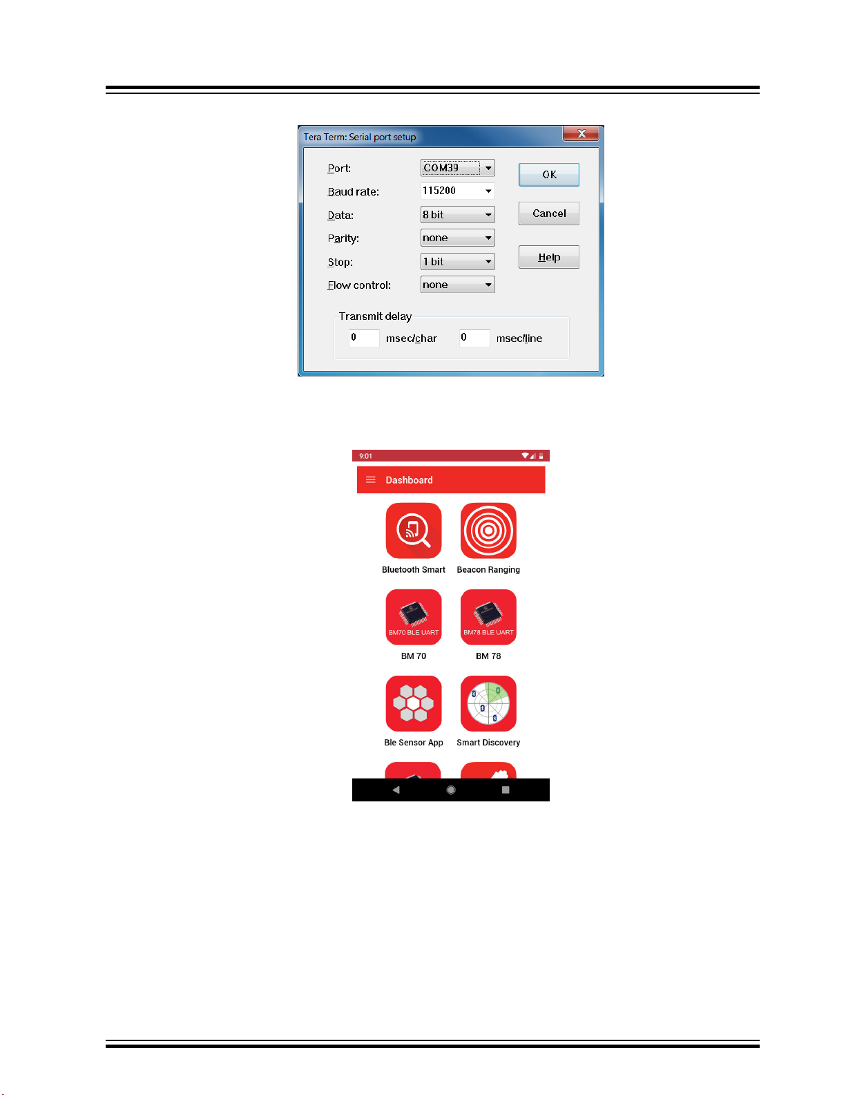
4. Start the Terminal Emulator software. In this example, TeraTerm is used. Configure the serial port settings of
the enumerated COM port as shown in the following figure.
© 2019 Microchip Technology Inc.
DS50002891A-page 7
Page 8
BM71-XPro
Module Configuration
Figure 3-1. TeraTerm Serial Port Setup
5. Open the MBD app on the phone/tablet. Ensure that the Bluetooth is turned ON in the device.
6. On Dashboard, select “BM70”, see the following figure.
Figure 3-2. MBD Dashboard
7. In the follow-up screen, click Scan and “Scan” again at the bottom.
8. Once the scanning process completes, the BM71 module should appear as “BM71_BLE” by default.
© 2019 Microchip Technology Inc.
DS50002891A-page 8
Page 9
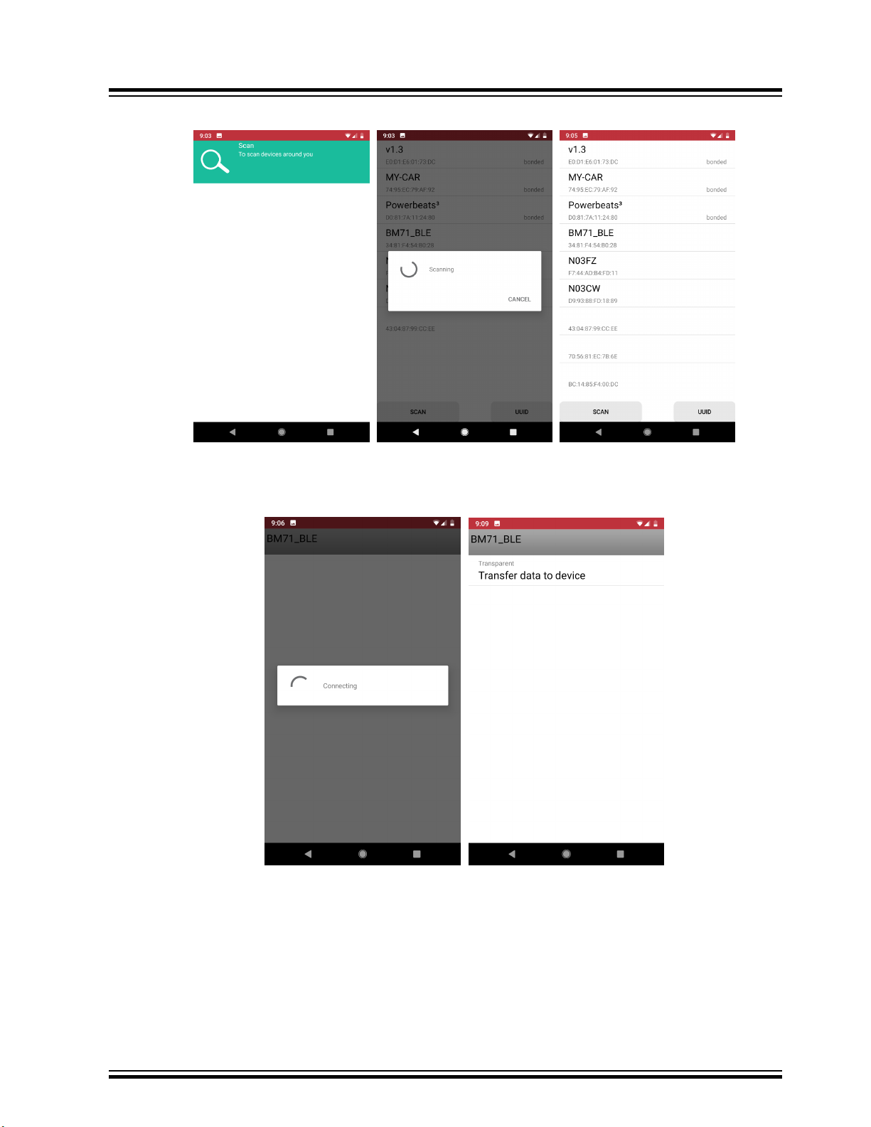
Figure 3-3. MBD Scanning Process
BM71-XPro
Module Configuration
9. Click on the “BM71_BLE” to start a connection process. Once connected, the transparent UART service
available on the BM71 module should show up.
Figure 3-4. MBD Connecting to BM71 XPRO
10. Click on “Transfer data to device”. The Transparent UART screen should open (see following figure). The data
pipe is now open.
© 2019 Microchip Technology Inc.
DS50002891A-page 9
Page 10
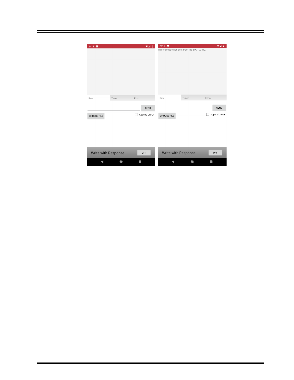
Figure 3-5. MBD Data Pipe
BM71-XPro
Module Configuration
11. In the serial emulator application (TeraTerm), enter any text and this should show up in the transparent UART
page in the app.
3.2 Configuring the BM71 Module to Operate in Manual Mode (Host PC)
Hardware/Software required:
• BM71-XPro board; Mini-USB cable.
• A PC host supporting USB CDC virtual serial port. BM71-XPro board uses MCP2200 USB to UART bridge. The
drivers can be downloaded from http://www.microchip.com/MCP2200.
• BM71 emulator tools: UI Tool. These tools can be download from the BM71 webpage.
The procedure to change the BM71 to Manual mode via host PC is given below:
1. Ensure that the BM71-XPro board is configured as follows:
1.1. Middle jumper on J2 is closed to select USB power option.
1.2. The current measurement jumper on J3 is present.
1.3. Switch 2 (blue LED) on the DIP switch is set to ON.
2. Connect the BM71-XPro board to the host PC using the mini-USB cable. Ensure that the green LED (LD1) is
solid ON indicating USB power.
3. Connect BM71-XPro board to the host PC using micro-USB cable. Verify the virtual COM port is enumerated
on the host PC. If the COM port does not enumerate, the MCP2200 drivers may be missing from the host PC.
If needed, the drivers can be downloaded from the http://www.microchip.com/MCP2200 web page.
4. Set switch 1 (system configuration) on the DIP switch to ON. Press the Reset button (SW1). The blue LED
(LD4) should turn to a solid ON.
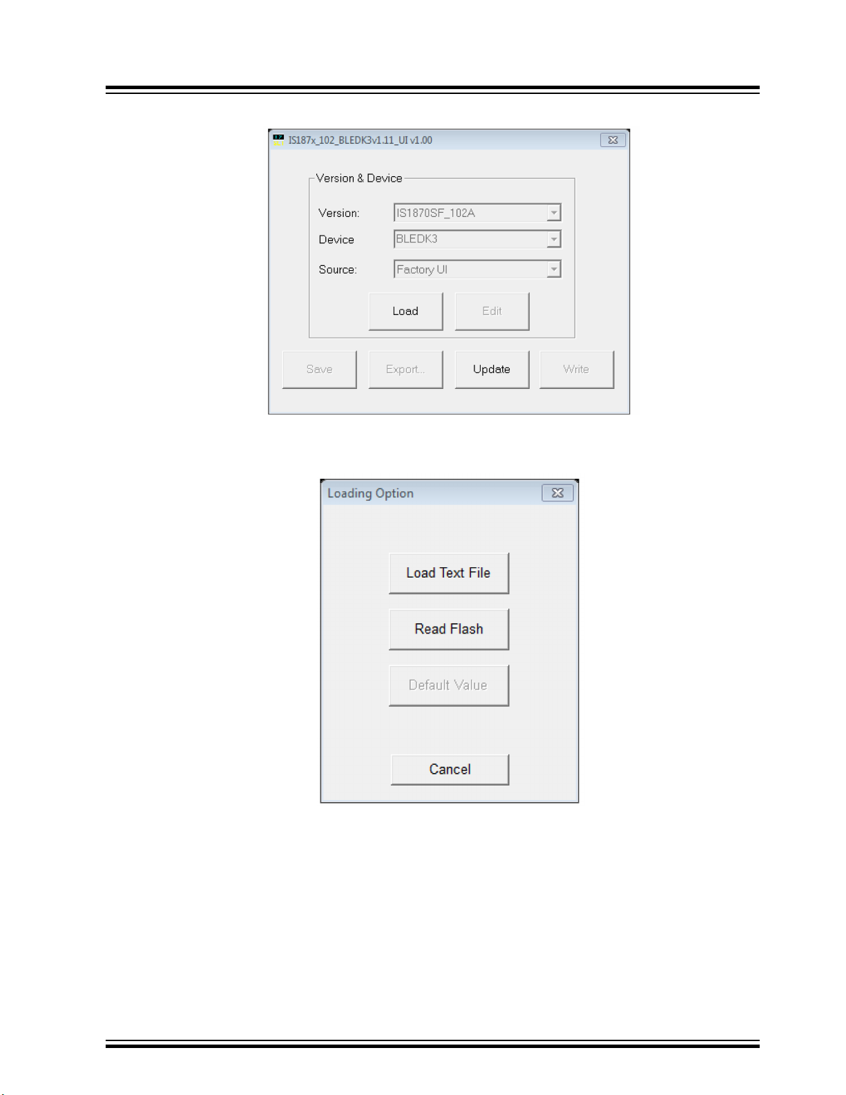
5. Open the UI tool (see the following figure) and Click on ‘Load’.
© 2019 Microchip Technology Inc.
DS50002891A-page 10
Page 11
Module Configuration
Figure 3-6. UI Tool
6. In the ‘Loading Option’ dialog box, select “Load Text File” option (see the following figure)
Figure 3-7. Loading Option
BM71-XPro
7. In the file browser, select “IS1871SF_102_BLEDK3v1.11_UI v1.00(BM71)_default.txt”
8. In the UI tool dialog box, click on “Edit”
© 2019 Microchip Technology Inc.
DS50002891A-page 11
Page 12
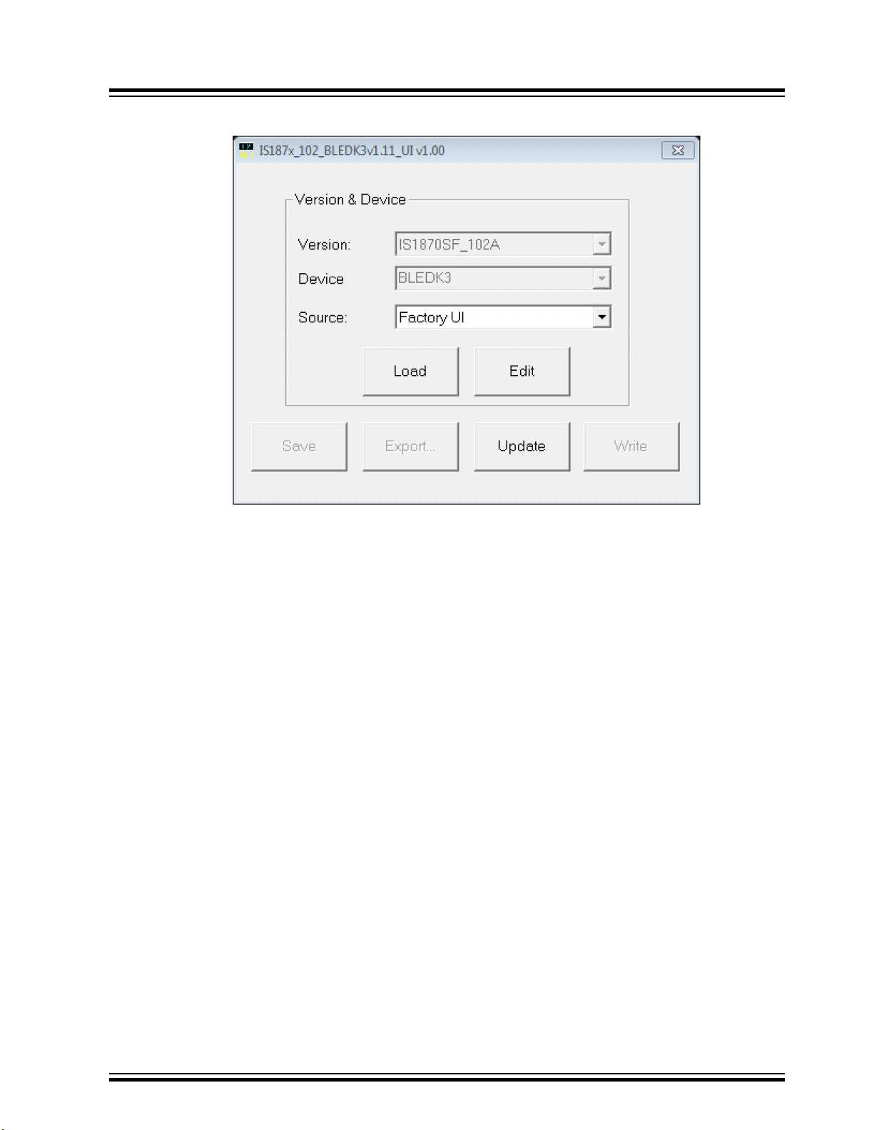
Figure 3-8. UI Tool - Editing
BM71-XPro
Module Configuration
9. Click ‘OK’ in ‘Feature’ dialog box.
10. In the UI Tool, under the ‘System Setup’:
10.1. Set the UART_RX_IND (Low power operation) to ‘Disable’ from the drop-down menu.
10.2. Set the Operation mode to “Manual Pattern” under the ‘Operation mode setting’ section.
11. Click ‘Finish’
12. In the UI Tool, click ‘Write’ (see following figure)
© 2019 Microchip Technology Inc.
DS50002891A-page 12
Page 13

Figure 3-9. UI tool: Select ‘Write’
BM71-XPro
Module Configuration
13. In the ‘Read/Write Flash’ dialog box, select an appropriate COM port and click on ‘Write’. In the confirmation
window, click ‘Yes’ to update EFLASH.
Figure 3-10. Read / Write Flash
14. After the successful Flash write, a confirmation message will be flashed as shown in the following figure.
© 2019 Microchip Technology Inc.
DS50002891A-page 13
Page 14

Module Configuration
Figure 3-11. Write Confirmation
15. Close the UI tool.
16. Set switch 1 (system configuration) on the DIP switch to ON. Press the Reset button (SW1). The blue LED
(LD4) should blink intermittently.
17. The module is now set to work in Manual mode.
3.3 Connecting the BM71-XPro to MBD App in Manual Mode (Host PC)
Hardware/Software required:
• BM71-XPro board; Mini-USB cable.
• A PC host supporting USB CDC virtual serial port. BM71-XPro board uses MCP2200 USB to UART bridge. The
drivers can be downloaded from http://www.microchip.com/MCP2200.
• BM71 emulator tools: UI Tool and Manual pattern tool. These tools can be download from the BM71 webpage.
• Microchip MBD app for iOS or Android. Available in:
– App Store (IOS) for iPhones
– Google Play Store for Android devices
To configure the module to operate in Manual mode, follow the procedure described in the 3.2 Configuring the BM71
Module to Operate in Manual Mode (Host PC). The procedure to connect to a peer device (phone/tablet) in Manual
mode is given below:
1. Ensure that the BM71-XPro board is configured as follows:
1.1. Middle jumper on J2 is closed to select USB power option.
1.2. The current measurement jumper on J3 is present.
1.3. Switch 1 (system configuration) on the DIP switch is set to OFF.
1.4. Switch 2 (blue LED power) on the DIP switch is set to ON.
2. Connect the BM71-XPro board to the host PC using the mini-USB cable. Ensure that green LED (LD1) is solid
ON indicating USB power.
3. Connect BM71-XPro to the host PC using micro-USB cable. Verify the virtual COM port is enumerated on host
PC. If the COM port does not enumerate, the MCP2200 drivers may be missing from the host PC. If needed,
the drivers can be downloaded from the http://www.microchip.com/MCP2200 webpage.
4. Press the Reset button (SW1) and verify that the blue LED (LD4) is flashing intermittently.
5. Open the manual pattern tool. Select the enumerated COM port for the BM71-XPro board in the COM port
drop down list (top-left - see following figure) and click ‘Connect’. The ‘Connect’ button should change to
‘Disconnect’ upon a successful connection.
BM71-XPro
© 2019 Microchip Technology Inc.
DS50002891A-page 14
Page 15

Figure 3-12. Manual Test Tool
BM71-XPro
Module Configuration
6. To verify the module information (not mandatory), in the ‘Common’ tab (left side), under the ‘Common
Command’ section, select ‘0x01: Read Local Information’ for the ‘Opcode’ field. Click ‘Send’ (see following
figure). The module will respond with the Bluetooth MAC address, firmware version and hardware version. The
response is shown in the “Log view” window.
© 2019 Microchip Technology Inc.
DS50002891A-page 15
Page 16

Figure 3-13. Read Local Information
BM71-XPro
Module Configuration
7. To begin advertising, enter the ‘GAP’ tab, under the ‘GAP Command’ section, select the following options for
each field (see following figure):
7.1. Select “0x1C: Set Adv Enable” for Opcode field.
7.2. Select “0x01: Enter Standby Mode” for the Standby mode field.
7.3. Click “Send”.
8. Once the module enters the Standby mode (started advertising), the BT Status field will be updated (see the
following figure).
© 2019 Microchip Technology Inc.
DS50002891A-page 16
Page 17

Figure 3-14. Start Advertising
BM71-XPro
Module Configuration
9. Open the MBD app on the phone/tablet. Ensure that the Bluetooth is turned ON in the device.
10. On Dashboard, select “BM70”, see the following figure.
© 2019 Microchip Technology Inc.
DS50002891A-page 17
Page 18

Figure 3-15. MBD Dashboard
BM71-XPro
Module Configuration
11. In the follow-up screen, click Scan and “Scan” again at the bottom.
12. Once the scanning process completes, the BM71 module should appear as “BM71_BLE” by default.
Figure 3-16. MBD Scanning Process
13. Click on the “BM71_BLE” to start a connection process. Once connected, the transparent UART service
available on the BM71 module should show up.
© 2019 Microchip Technology Inc.
DS50002891A-page 18
Page 19

Figure 3-17. MBD Connecting to BM71-XPro
BM71-XPro
Module Configuration
14. The manual tool should show the connection details once the connection from the peer device (phone/tablet)
is successfully executed (see the following figure).
© 2019 Microchip Technology Inc.
DS50002891A-page 19
Page 20

Figure 3-18. Connecting from a Peer Device
BM71-XPro
Module Configuration
15. On the MBD app, click on “Transfer data to device”. The Transparent UART screen should open. Ensure that
the ‘Write with Response’ in the app is set to ON. The data pipe is now open.
© 2019 Microchip Technology Inc.
DS50002891A-page 20
Page 21

Figure 3-19. MBD Data Pipe
ON
BM71-XPro
Module Configuration
16. The manual tool should provide the message for the data pipe in the log view (see following figure).
© 2019 Microchip Technology Inc.
DS50002891A-page 21
Page 22

Figure 3-20. Open a Transparent UART Data Pipe
BM71-XPro
Module Configuration
17. Go to the ‘Transparent’ tab on the manual tool. Check operation of the data pipe, by entering data in the app or
in the ‘Send Data’ field in the manual tool.
© 2019 Microchip Technology Inc.
DS50002891A-page 22
Page 23

Figure 3-21. Transparent UART Data Pipe Testing
BM71-XPro
Module Configuration
18. The transparent UART data pipe is now operational in Manual mode.
3.4 Using the BM70/71 MCU drivers
Microchip offers a library of MCU drivers for the BM70/71 modules integrated into the Harmony and ASF3 for
MPLAB® and Atmel Studio, respectively. This section describes how to access the BM71 MCU drivers from ASF3
library in Atmel Studio.
Hardware/software required:
• Atmel Studio 7.x7.0 with ASF3 installed (version 3.44.0 or later).
• SAML21 Xplained Pro board.
• BM71-XPro board.
To use the BM71 MCU drivers in ASF3, the BM71-XPro board needs to be connected to EXT1 header of the BM71XPro board (see following figure).
© 2019 Microchip Technology Inc.
DS50002891A-page 23
Page 24

Figure 3-22. BM71-XPro Board Connected to the SAML21 Xplained Pro
BM71-XPro
Module Configuration
1. Connect to the BM71-XPro board to EXT1 header of the SAML21 Xplained Pro board. Open Atmel Studio
software. On the top menu, select ‘File’ → ‘New’ → ‘Example Project’.
2. In the ‘New Example Project’ dialog box
2.1. Select Device Family: as “SAML21” from the drop down list and enter ‘ble_host_sdk’ in the search
field as shown in the following figure. The list of example projects should be available in the ‘All
Projects’ tab. (If not visible, try clicking on the horizontal triangle to expand the list under ‘Atmel-Atmel
Corp.’ header.
© 2019 Microchip Technology Inc.
DS50002891A-page 24
Page 25

Figure 3-23. Opening an Example Project for BM71-XPro Board
BM71-XPro
Module Configuration
3. The list of available example projects is provided. Select any project to get started. In the preceding figure, the
iBeacon was selected as an example. Click OK in the succeeding dialog box to accept the terms and
conditions. The iBeacon example will now be loaded as can be seen in the following Solution Explorer window.
© 2019 Microchip Technology Inc.
DS50002891A-page 25
Page 26

Figure 3-24. Solution Explorer window in Atmel Studio
BM71-XPro
Module Configuration
Note: For more instructions on executing the project, click on the
‘iBeacon_Demo_Getting_Started_Guide.pdf’ file for details.
4. Follow the instructions in the getting started guide to build, load, and test the project.
© 2019 Microchip Technology Inc.
DS50002891A-page 26
Page 27

Appendix A. Updating the BM71 Module Firmware
4. Appendix A. Updating the BM71 Module Firmware
The firmware in the BM71 module can be updated using a PC Tool isupdate.exe over the USB port. The latest BM71
firmware images and the isupdate.exe tool are available from the BM71 product webpage.
The procedure to change/update the firmware on the BM71 module using the host PC utility is given below:
1. Download the firmware zip file from the BM71 webpage and extract the contents. The zip file contains the
isupdate.exe utility and a folder including the firmware images.
2. Connect the BM71-XPro board to the host PC using the micro-USB cable.
3. Verify that swtich#1 of the DIP switch (SW2) is set to ON position. Press Reset button (SW1) and verify that
the blue LED (LD4) is solid ON indicating that the BM71 is in Memory Programming mode.
4. Launch the isupdate.exe application. In the tool:
4.1. Select the COM port used by the BM71-XPro board.
4.2. Verify that other settings (baud, memory type, and address) are set as follows:
4.2.1. Baudrate: 115200
4.2.2. Memory type/subtype: Flash/Embedded
4.2.3. Address: 0000
Figure 4-1. Firmware Update Tool
BM71-XPro
4.3. Click the Connect button and verify that the “Port connect -> COMxx” is displayed in the text box.
4.4. Verify firmware update is successfully completed. The “End of Write Memory” message is displayed.
4.5. Click the Disconnect button to close the COM port.
4.6. Set switch 1 in DIP switch SW2 to the ‘1’ position for Application mode.
© 2019 Microchip Technology Inc.
DS50002891A-page 27
Page 28

Appendix B. Schematics and Bill of Materia...
5. Appendix B. Schematics and Bill of Materials
The schematic and the Bill of Materials (BOM) for the BM71-XPro board are provided below.
BM71-XPro
© 2019 Microchip Technology Inc.
DS50002891A-page 28
Page 29

USB Device / +5V Input Power
GNDE
GNDE
+VUSB_FUSED
Overcurrent
USB_D_N
USB_D_P
GNDE
ESD Protection
NOTE: Place near the USB connector
USB_D_N_CON
USB_D_P_CON
Short and wide traces to power and GND
GND
GND GND
GND
ID
HCI_RX_R HCI_TX_R
SPI_SS_ASPI_MOSI
SPI_MISOSPI_SCK
Extension Connector
GND
GND
GNDGND GND
+VDD_USB
GND GND
GND
GND
Power Source Select
+VDD_R
HCI_TX_USB
GND GNDGND
GND
GND
Radio Module
USB-UART Bridge
< HCI_RX_HOSTHCI_TX_HOST<
HCI_TX_R
HCI_RX_R
USB Traffic LEDs
GND
Reset Circuit
Reset Switch
HCI_TX_R
HCI_RX_R
HCI_RX_R
HCI_TX_R
GND
HCI_BUS HCI_BUS
HCI_BUS
ID Device
RST>
< HCI_RTS_R
HCI_CTS_R
HCI_RTS_R
HCI_CTS_RHCI_RTS_USB
MCU_CTS/GPIO2
HCI_CTS_R
GND
GND
GND
Protection
GND
IO_BUS
IO_BUS IO_BUS
LED_BLUE
LED_BLUE
P2_0/MODE
P2_0/MODE
GND
GND
SPI_SCK
SPI_MISO
SPI_MOSI
P1_3
P1_3
On-Board Flash Memory
5V to 3.3V LDO
USB_TX
USB_RX
USB_P
GND
BT_ACT
SPI_SS_A
ADC1ADC2
PWM+PWM-
IRQ/GPIO
I2C_SDAI2C_SCL
MCU_RTS/GPIO1
HCI_RTS_R
P1_2
P1_6
P1_7
P2_7
P1_2
P1_6
P1_7
P2_7
SPI_SS_B/GPIO
AD10
DIO/RX_IND
AD14/TX_IND
GND GND
MCU_PWM+
MCU_PWM+
MCU_PWM-
MCU_PWM-
Optional RC Filters For PWM to Module ADC Usage
RST P2_0/MODE
IRQ/GPIO
IRQ/GPIO
TX_IND
AD14
GND
Module Current Measure
+VDD_EXT
+VDD_EXT
+VDD_EXT
+VDD_EXT
+VDD
+VDD
USB/EXT
+VDD
+VDD_USB +VDD_USB
MF-FSMF050XF1FUSE
470R
R1
470R
R5
470R
R6
470R
R7
270R
R8
270R
R9
1M
R10
27R
R11
0R
R13
0R
R14
100k
R15
0R
R16
0R
R17
DNP
0R
R18
100k
R19
DNPDNP
10nF
C1
1uF
C2
1uF
C3
1nF
C8
12pF
C9
12pF
C10
4.7uF
C11
1uF
C13
1uF
C14
2 1
BAT54HT1G
D1
SCHOTTKY_SMD_12
2 1
BAT54HT1G
D3
SCHOTTKY_SMD_12
21
SML-310MTT86N
LD1
21
SML-310MTT86N
LD2
21
SML-310MTT86N
LD3
21
19-117/BHC-YJ2K2TX/3T
LD4
LED_12
1
2
MTSW-102-08-L-S-276
J3
1
2
3
MTSW-103-08-L-S-276
J2
SNT-100-BK-G
JP1
SNT-100-BK-G
JP2
KSR211GLFS
SW1
1 2 3 4 5
IDD+D-+5V GND
Micro-AB Recep tacle
Shield
Shield
105017-0001
J1
USB_AB
GND
1
VIN
3
VOUT
2
MCP1700/3.3V
U1
IO
5
NC0
6
GND
4
VCC
8
PAD
9
NC
1
NC2NC3NC
7
ATSHA204A SWI UDFN8
U5
ATSHA204A-SWI
56
1
34278
910
1112
1314
1516
1718
1920
2185-210RS0CYNT1
J4
PT-5012-KEYSTONE_2
TP1
PT-5012-KEYSTONE_2
TP2
SJ-5076
RP1
RUBBER FEE T
SJ-5076
RP2
RUBBER FEE T
1
234561112
13
1089
7
1817
192016
15
14
RST
GP7/TxLED
GP6/RxLED
GP5
GP4
GP3
GP2
GP1/USB-CFG
GP0/SSPND
CTS
RTS
RX
TX
VDDVSS
OSC1
OSC2
D+
D-
VUSB
EP
21
MCP2200-I/MQ
U3
MCP2200 QFN-20
123 4
5
6
USBLC6-2SC6
D2
VDD
3
VOUT
1
VSS
2
MCP112/1.9V
U2
1 2
3
CSTCE12M0G15L99-R0
X1
P0_0
11
RST
10
P2_7
15
GND13GND
2
P1_2
3
UART_TX
8
P1_6
6
P2_0
16
UART_RX
7
P1_7
5
P1_3
4
P3_6
9
BT_RF
1
VBAT
14
P0_2
12
BM71BLES1FC2
U4
47uF
C6
$ >_
A11-0433
TEST1
A12-1361
PCBADOC1
A12-1362
TESTDOC1
100n
C5
100n
C4
100n
C7
100n
C12
4.7k
R2
4.7k
R4
4.7k
R12
10k
R3
A08-2951
BM71 Xplained Pro PCB
PCB1
Prod uct nu mber /revision
Serial nu mber
Label PCBA
LABEL1
123 4
5
6
On
DSI-03H
SW2
#CE1SO2#WP3VSS
4
SI
5
SCK
6
#HOLD
7
VDD
8
U6
SST25VF080B
BM71-XPro
Appendix B. Schematics and Bill of Materia...
© 2019 Microchip Technology Inc.
Figure 5-1. BM71-XPro Schematic
DS50002891A-page 29
Page 30

BM71-XPro
Appendix B. Schematics and Bill of Materia...
Supplier 1 Supplier Part Number 1 Populated Quantity MCHP-ID
1
Murata GRM155R71E103KA01D Digi-Key 490-1312-2-ND YES 1 CAP1071
Murata GRM155R61C105KE01D Digi-Key 490-10453-2-ND YES 2 CAP1065
GRM188R60J476ME15D Digi-Key 490-13247-1-ND YES 1 CAP1661
Murata GRM155R71C104KA88D Digi-Key 490-3261-2-ND Yes 4 CAP1033
Murata Electronics
06032C102KAT2A Digi-Key 478-1194-1-ND YES 1 CAP1591
GRM1555C1H120FA01D Digi-Key 490-6196-2-ND YES 2 CAP1367
Corporation
Murata Electronics
AVX Corporation AVX
North America
TDK Corporation C1005X5R1A475K050BC Digi-Key 445-13820-1-ND YES 1 CAP1684
Murata GRM155R61C105KE01D Digi-Key 490-10453-2-ND DNP 0 CAP1065
North America
STMicroelectronics USBLC6-2SC6 Digi-Key 497-5235-1-ND YES 1 DIODE1148
STMicroelectronics BAT54JFILM Digi-Key 497-7163-1-ND Yes 2 DIODE0182
Littelfuse Inc. 1206L075THYR Digi-Key F3370CT-ND YES 1 RES1648
FCI 10118194-0001LF Digi-Key 609-4618-1-ND YES 1 CON1383
FCI 68000-103HLF Digi-Key 609-3461-ND Yes 1 CON1105
PPPC102LJBN-RC Digi-Key S5563-ND YES 1 CON1532
FCI 77311-118-02LF Digi-Key 609-4434-ND Yes 1 CON1108
Sullins Connector
Solutions
Dev Tools MECH 1 08-00028
Lumex SML-LX0603GW-TR Digi-Key 67-1549-1-ND YES 3 LED0120
CAP CER 0.1uF 16V 10% X7R SMD
0402
4 C4, C5, C7,
0402
C12
SMD 0402
Quantity Designator Description_ Manufacturer 1 Manufacturer Part Number
1 C1 CAP CER 10000pF 50V 10% X7R
Table 5-1. Bill of Materials
2 C2, C3 CAP CER 1uF 16V 10% X5R SMD
© 2019 Microchip Technology Inc.
0402
0402
0603
SMD 0603
2 C9, C10 CAP CER 12pF 50V 1% NP0 SMD
1 C6 CAP CER 47uF 6.3V 20% X5R SMD
1 C8 CAP CER 1000pF 200V 10% X7R
1 C11 CAP CER 4.7uF 10V 10% X5R SMD
0402
0 C13, C14 CAP CER 1uF 16V 10% X5R SMD
SMD 1206
SMD SOT-23-6
40V SOD-323
1 F1 RES FUSE 750mA 8V 0.2s Poly
1 D2 DIO TVSARR USBLC6-2SC6 5.25V
2 D1, D3 DIO SCTKY BAT54 900mV 300mA
TH/SMD R/A
1 J1 CON USB2.0 MICRO-B FEMALE
Rotated 180Degrees Gold TH RT
5.84MH TH VERT
5.84MH TH VERT
1 J3 CON HDR-2.54 Male 1x2 Gold
1 J2 CON HDR-2.54 Male 1x3 Gold
ANGLE
1 J4 CON HDR-2.54 Female 2x10
2 JP1, JP2 MECH HW JUMPER 2.54mm 1x2 3M 969102-0000-DA Digi-Key 3M9580-ND MECH 2 HW1006
DS50002891A-page 30
(SMALL MODULES) PER MTS-0002
Diffuse SMD 0603
1 LABEL LABEL, ASSY W/REV LEVEL
3 LD1, LD2, LD3 DIO LED GREEN 2.2V 25mA 18mcd
Page 31

BM71-XPro
Appendix B. Schematics and Bill of Materia...
YES 1 IC1400
DSS-03-B-PF YES 1 SWITCH1042
Supplier 1 Supplier Part Number 1 Populated Quantity MCHP-ID
1
Panasonic ERJ-2GEJ471X Digi-Key P470JCT-ND Yes 4 RSMT0337
Lite-On LTST-C193TBKT-5A Digi-Key 160-1827-1-ND YES 1 DIODE1056
Panasonic ERJ-2GEJ271X Digi-Key P270JTR-ND YES 2 RES1027
ERJ-2RKF27R0X Digi-Key P27.0LTR-ND YES 1 RES1823
Components
C&K Components RS-282G05A3-SM RT Digi-Key CKN10384CT-ND YES 1 SWITCH1057
3M SJ5076BLACK Farnell 1165061 MECH 2 MECH0087
ELECTRONICS
CO., LTD.
DSS-03-B-PF ROKI
ROKI ELECTRONICS
CO., LTD.
Microchip MCP1700T-3302E/TT Microchip MCP1700T-3302E/TT Yes 1 MIC0598
Microchip Technology MCP112T-195I/TT Mouser 579-MCP112T-195I/TT YES 1 MIC7057
Microchip Technology MCP2200-I/MQ Digi-Key MCP2200-I/MQ-ND YES 1 MIC6326
Microchip BM71BLES1FC2 Microchip BM71BLES1FC2 YES 1 MIC6577
0402
Clear SMD 0603
3 R2, R4, R12 RES TKF 4.7k 5% 1/10W SMD 0402 Panasonic ERJ-2GEJ472X Digi-Key P4.7KJCT-ND Yes 3 RSMT0734
Quantity Designator Description_ Manufacturer 1 Manufacturer Part Number
...........continued
4 R1, R5, R6, R7 RES TKF 470R 5% 1/16W SMD
1 LD4 DIO LED BLUE 2.8V 20mA 15mcd
1 R3 RES TKF 10k 5% 1/10W SMD 0402 Panasonic ERJ-2GEJ103X Digi-Key P10KJCT-ND Yes 1 RSMT0735
© 2019 Microchip Technology Inc.
0402
2 R8, R9 RES TKF 270R 5% 1/10W SMD
1 R10 RES TKF 1M 5% 1/16W SMD 0402 Yageo RC0402JR-071ML Digi-Key 311-1.0MJRCT-ND YES 1 RES1019
RES TKF 0R SMD 0402 Panasonic ERJ-2GE0R00X Digi-Key P0.0JCT-ND Yes 4 RSMT0730
R16, R18
2 R15, R19 RES TKF 100k 5% 1/10W SMD 0402 Panasonic ERJ-2GEJ104X Digi-Key P100KJCT-ND Yes 2 RSMT0737
4 R13, R14,
1 R11 RES TKF 27R 5% 1/10W SMD 0402 Panasonic Electronic
flat top D8H2.8 Black
0 R17 RES TKF 0R SMD 0402 Panasonic ERJ-2GE0R00X Digi-Key P0.0JCT-ND DNP 0 RSMT0730
2 RP1, RP2 MECH HW RUBBER PAD Cylindrical
DSS-03-B-PF TH
RS-282G05A3-SM RT
1 SW2 SWITCH DIP 3 SPST 24VDC 25MA
1 SW1 SWITCH TACT SPST 12V 50mA
MCP1700T-3302E/TT SOT-23-3
2 TP1, TP2 CON TP LOOP Black TH Keystone 5011 Digi-Key 36-5011-ND YES 2 MISC0025
1 U1 MCHP ANALOG LDO 3.3V
1 U2 MCHP ANALOG VOLATGE
DETECTOR 1.9V MCP112T-195I/TT
SOT-23-3
MCP2200-I/MQ QFN-20
BM71BLES1FC2 MODULE-16
ATSHA204A-MAHCZ-T UDFN-8
1 U3 MCHP INTERFACE USB UART
1 U4 MCHP RF BLUETOOTH
1 U5 IC Crypto Element SHA-256 1-Wire
DS50002891A-page 31
Page 32

YES 1 MIC5599
SAF-T
BM71-XPro
Appendix B. Schematics and Bill of Materia...
Supplier 1 Supplier Part Number 1 Populated Quantity MCHP-ID
1
Microchip SST25VF040B-50-4I-SAF-T Microchip SST25VF040B-50-4I-
Murata CSTCE12M0G15L99-R0 Digi-Key 490-7848-1-ND YES 1 OSC1027
50MHz SST25VF040B-50-4I-SAF
SOIC-8
CSTCE-G
Quantity Designator Description_ Manufacturer 1 Manufacturer Part Number
...........continued
1 U6 MCHP MEMORY SERIAL FLASH 4M
1 X1 RESONATOR 12MHz 0.1% SMD
© 2019 Microchip Technology Inc.
DS50002891A-page 32
Page 33

6. Agency Certification
This equipment (SAM R34 Xplained Pro Evaluation Kit/A09-3167) is intended for evaluation purposes only. The
following regulatory notices are to cover the requirements under the regulatory approval.
6.1 Europe
This equipment (A09-3167) has been assessed under the Radio Equipment Directive (RED) for use in European
Union countries. A Declaration of Conformity must be issued for each of these standards and kept on file as
described in Radio Equipment Directive.
Furthermore, the manufacturer must maintain a copy of the module's documentation and ensure the final product
does not exceed the specified power ratings, antenna specifications, and/or installation requirements as specified in
the user manual. If any of these specifications are exceeded in the final product, a submission must be made to a
notified body for compliance testing to all required standards.
Important: On account of the nature of radio equipment, the height of the CE marking affixed to radio
equipment may be lower than 5 mm, provided that it remains visible and legible. More detailed information
about CE marking requirements, refer Article 19 of "DIRECTIVE 2014/53/EU OF THE EUROPEAN
PARLIAMENT AND OF THE COUNCIL" of 16 April 2014.
BM71-XPro
Agency Certification
SIMPLIFIED EU DECLARATION OF CONFORMITY
Hereby, Microchip Technology Inc. declares that the radio equipment type [A09-3110] is in compliance with Directive
2014/53/EU.
The full text of the EU declaration of conformity is available at the following internet address (refer product specific
pages): http://www.microchip.com/design-centers/wireless-connectivity/.
© 2019 Microchip Technology Inc.
DS50002891A-page 33
Page 34

7. Document Revision History
Revision Date Section Description
A 07/2019 Document Initial Revision
BM71-XPro
Document Revision History
© 2019 Microchip Technology Inc.
DS50002891A-page 34
Page 35

BM71-XPro
The Microchip Website
Microchip provides online support via our website at http://www.microchip.com/. This website is used to make files
and information easily available to customers. Some of the content available includes:
• Product Support – Data sheets and errata, application notes and sample programs, design resources, user’s
guides and hardware support documents, latest software releases and archived software
• General Technical Support – Frequently Asked Questions (FAQs), technical support requests, online
discussion groups, Microchip design partner program member listing
• Business of Microchip – Product selector and ordering guides, latest Microchip press releases, listing of
seminars and events, listings of Microchip sales offices, distributors and factory representatives
Product Change Notification Service
Microchip’s product change notification service helps keep customers current on Microchip products. Subscribers will
receive email notification whenever there are changes, updates, revisions or errata related to a specified product
family or development tool of interest.
To register, go to http://www.microchip.com/pcn and follow the registration instructions.
Customer Support
Users of Microchip products can receive assistance through several channels:
• Distributor or Representative
• Local Sales Office
• Embedded Solutions Engineer (ESE)
• Technical Support
Customers should contact their distributor, representative or ESE for support. Local sales offices are also available to
help customers. A listing of sales offices and locations is included in this document.
Technical support is available through the web site at: http://www.microchip.com/support
Microchip Devices Code Protection Feature
Note the following details of the code protection feature on Microchip devices:
• Microchip products meet the specification contained in their particular Microchip Data Sheet.
• Microchip believes that its family of products is one of the most secure families of its kind on the market today,
when used in the intended manner and under normal conditions.
• There are dishonest and possibly illegal methods used to breach the code protection feature. All of these
methods, to our knowledge, require using the Microchip products in a manner outside the operating
specifications contained in Microchip’s Data Sheets. Most likely, the person doing so is engaged in theft of
intellectual property.
• Microchip is willing to work with the customer who is concerned about the integrity of their code.
• Neither Microchip nor any other semiconductor manufacturer can guarantee the security of their code. Code
protection does not mean that we are guaranteeing the product as “unbreakable.”
Code protection is constantly evolving. We at Microchip are committed to continuously improving the code protection
features of our products. Attempts to break Microchip’s code protection feature may be a violation of the Digital
Millennium Copyright Act. If such acts allow unauthorized access to your software or other copyrighted work, you
may have a right to sue for relief under that Act.
Legal Notice
Information contained in this publication regarding device applications and the like is provided only for your
convenience and may be superseded by updates. It is your responsibility to ensure that your application meets with
© 2019 Microchip Technology Inc.
DS50002891A-page 35
Page 36

BM71-XPro
your specifications. MICROCHIP MAKES NO REPRESENTATIONS OR WARRANTIES OF ANY KIND WHETHER
EXPRESS OR IMPLIED, WRITTEN OR ORAL, STATUTORY OR OTHERWISE, RELATED TO THE INFORMATION,
INCLUDING BUT NOT LIMITED TO ITS CONDITION, QUALITY, PERFORMANCE, MERCHANTABILITY OR
FITNESS FOR PURPOSE. Microchip disclaims all liability arising from this information and its use. Use of Microchip
devices in life support and/or safety applications is entirely at the buyer’s risk, and the buyer agrees to defend,
indemnify and hold harmless Microchip from any and all damages, claims, suits, or expenses resulting from such
use. No licenses are conveyed, implicitly or otherwise, under any Microchip intellectual property rights unless
otherwise stated.
Trademarks
The Microchip name and logo, the Microchip logo, Adaptec, AnyRate, AVR, AVR logo, AVR Freaks, BesTime,
BitCloud, chipKIT, chipKIT logo, CryptoMemory, CryptoRF, dsPIC, FlashFlex, flexPWR, HELDO, IGLOO, JukeBlox,
KeeLoq, Kleer, LANCheck, LinkMD, maXStylus, maXTouch, MediaLB, megaAVR, Microsemi, Microsemi logo, MOST,
MOST logo, MPLAB, OptoLyzer, PackeTime, PIC, picoPower, PICSTART, PIC32 logo, PolarFire, Prochip Designer,
QTouch, SAM-BA, SenGenuity, SpyNIC, SST, SST Logo, SuperFlash, Symmetricom, SyncServer, Tachyon,
TempTrackr, TimeSource, tinyAVR, UNI/O, Vectron, and XMEGA are registered trademarks of Microchip Technology
Incorporated in the U.S.A. and other countries.
APT, ClockWorks, The Embedded Control Solutions Company, EtherSynch, FlashTec, Hyper Speed Control,
HyperLight Load, IntelliMOS, Libero, motorBench, mTouch, Powermite 3, Precision Edge, ProASIC, ProASIC Plus,
ProASIC Plus logo, Quiet-Wire, SmartFusion, SyncWorld, Temux, TimeCesium, TimeHub, TimePictra, TimeProvider,
Vite, WinPath, and ZL are registered trademarks of Microchip Technology Incorporated in the U.S.A.
Adjacent Key Suppression, AKS, Analog-for-the-Digital Age, Any Capacitor, AnyIn, AnyOut, BlueSky, BodyCom,
CodeGuard, CryptoAuthentication, CryptoAutomotive, CryptoCompanion, CryptoController, dsPICDEM,
dsPICDEM.net, Dynamic Average Matching, DAM, ECAN, EtherGREEN, In-Circuit Serial Programming, ICSP,
INICnet, Inter-Chip Connectivity, JitterBlocker, KleerNet, KleerNet logo, memBrain, Mindi, MiWi, MPASM, MPF,
MPLAB Certified logo, MPLIB, MPLINK, MultiTRAK, NetDetach, Omniscient Code Generation, PICDEM,
PICDEM.net, PICkit, PICtail, PowerSmart, PureSilicon, QMatrix, REAL ICE, Ripple Blocker, SAM-ICE, Serial Quad
I/O, SMART-I.S., SQI, SuperSwitcher, SuperSwitcher II, Total Endurance, TSHARC, USBCheck, VariSense,
ViewSpan, WiperLock, Wireless DNA, and ZENA are trademarks of Microchip Technology Incorporated in the U.S.A.
and other countries.
SQTP is a service mark of Microchip Technology Incorporated in the U.S.A.
The Adaptec logo, Frequency on Demand, Silicon Storage Technology, and Symmcom are registered trademarks of
Microchip Technology Inc. in other countries.
GestIC is a registered trademark of Microchip Technology Germany II GmbH & Co. KG, a subsidiary of Microchip
Technology Inc., in other countries.
All other trademarks mentioned herein are property of their respective companies.
©
2019, Microchip Technology Incorporated, Printed in the U.S.A., All Rights Reserved.
ISBN: 978-1-5224-4789-4
Quality Management System
For information regarding Microchip’s Quality Management Systems, please visit http://www.microchip.com/quality.
© 2019 Microchip Technology Inc.
DS50002891A-page 36
Page 37

Worldwide Sales and Service
AMERICAS ASIA/PACIFIC ASIA/PACIFIC EUROPE
Corporate Office
2355 West Chandler Blvd.
Chandler, AZ 85224-6199
Tel: 480-792-7200
Fax: 480-792-7277
Technical Support:
http://www.microchip.com/support
Web Address:
http://www.microchip.com
Atlanta
Duluth, GA
Tel: 678-957-9614
Fax: 678-957-1455
Austin, TX
Tel: 512-257-3370
Boston
Westborough, MA
Tel: 774-760-0087
Fax: 774-760-0088
Chicago
Itasca, IL
Tel: 630-285-0071
Fax: 630-285-0075
Dallas
Addison, TX
Tel: 972-818-7423
Fax: 972-818-2924
Detroit
Novi, MI
Tel: 248-848-4000
Houston, TX
Tel: 281-894-5983
Indianapolis
Noblesville, IN
Tel: 317-773-8323
Fax: 317-773-5453
Tel: 317-536-2380
Los Angeles
Mission Viejo, CA
Tel: 949-462-9523
Fax: 949-462-9608
Tel: 951-273-7800
Raleigh, NC
Tel: 919-844-7510
New York, NY
Tel: 631-435-6000
San Jose, CA
Tel: 408-735-9110
Tel: 408-436-4270
Canada - Toronto
Tel: 905-695-1980
Fax: 905-695-2078
Australia - Sydney
Tel: 61-2-9868-6733
China - Beijing
Tel: 86-10-8569-7000
China - Chengdu
Tel: 86-28-8665-5511
China - Chongqing
Tel: 86-23-8980-9588
China - Dongguan
Tel: 86-769-8702-9880
China - Guangzhou
Tel: 86-20-8755-8029
China - Hangzhou
Tel: 86-571-8792-8115
China - Hong Kong SAR
Tel: 852-2943-5100
China - Nanjing
Tel: 86-25-8473-2460
China - Qingdao
Tel: 86-532-8502-7355
China - Shanghai
Tel: 86-21-3326-8000
China - Shenyang
Tel: 86-24-2334-2829
China - Shenzhen
Tel: 86-755-8864-2200
China - Suzhou
Tel: 86-186-6233-1526
China - Wuhan
Tel: 86-27-5980-5300
China - Xian
Tel: 86-29-8833-7252
China - Xiamen
Tel: 86-592-2388138
China - Zhuhai
Tel: 86-756-3210040
India - Bangalore
Tel: 91-80-3090-4444
India - New Delhi
Tel: 91-11-4160-8631
India - Pune
Tel: 91-20-4121-0141
Japan - Osaka
Tel: 81-6-6152-7160
Japan - Tokyo
Tel: 81-3-6880- 3770
Korea - Daegu
Tel: 82-53-744-4301
Korea - Seoul
Tel: 82-2-554-7200
Malaysia - Kuala Lumpur
Tel: 60-3-7651-7906
Malaysia - Penang
Tel: 60-4-227-8870
Philippines - Manila
Tel: 63-2-634-9065
Singapore
Tel: 65-6334-8870
Taiwan - Hsin Chu
Tel: 886-3-577-8366
Taiwan - Kaohsiung
Tel: 886-7-213-7830
Taiwan - Taipei
Tel: 886-2-2508-8600
Thailand - Bangkok
Tel: 66-2-694-1351
Vietnam - Ho Chi Minh
Tel: 84-28-5448-2100
Austria - Wels
Tel: 43-7242-2244-39
Fax: 43-7242-2244-393
Denmark - Copenhagen
Tel: 45-4450-2828
Fax: 45-4485-2829
Finland - Espoo
Tel: 358-9-4520-820
France - Paris
Tel: 33-1-69-53-63-20
Fax: 33-1-69-30-90-79
Germany - Garching
Tel: 49-8931-9700
Germany - Haan
Tel: 49-2129-3766400
Germany - Heilbronn
Tel: 49-7131-72400
Germany - Karlsruhe
Tel: 49-721-625370
Germany - Munich
Tel: 49-89-627-144-0
Fax: 49-89-627-144-44
Germany - Rosenheim
Tel: 49-8031-354-560
Israel - Ra’anana
Tel: 972-9-744-7705
Italy - Milan
Tel: 39-0331-742611
Fax: 39-0331-466781
Italy - Padova
Tel: 39-049-7625286
Netherlands - Drunen
Tel: 31-416-690399
Fax: 31-416-690340
Norway - Trondheim
Tel: 47-72884388
Poland - Warsaw
Tel: 48-22-3325737
Romania - Bucharest
Tel: 40-21-407-87-50
Spain - Madrid
Tel: 34-91-708-08-90
Fax: 34-91-708-08-91
Sweden - Gothenberg
Tel: 46-31-704-60-40
Sweden - Stockholm
Tel: 46-8-5090-4654
UK - Wokingham
Tel: 44-118-921-5800
Fax: 44-118-921-5820
© 2019 Microchip Technology Inc.
DS50002891A-page 37
 Loading...