

Page 1
BM70 PICtail
Evaluation Board (EVB)
™
/PICtail Plus
User’s Guide
2015-2016 Microchip Technology Inc. DS70005235C
Page 2

Note the following details of the code protection feature on Microchip devices:
YSTEM
CERTIFIED BY DNV
== ISO/TS 16949 ==
• Microchip products meet the specification contained in their particular Microchip Data Sheet.
• Microchip believes that its family of products is one of the most secure families of its kind on the market today, when used in the
intended manner and under normal conditions.
• There are dishonest and possibly illegal methods used to breach the code protection feature. All of these methods, to our
knowledge, require using the Microchip products in a manner outside the operating specifications contained in Microchip’s Data
Sheets. Most likely, the person doing so is engaged in theft of intellectual property.
• Microchip is willing to work with the customer who is concerned about the integrity of their code.
• Neither Microchip nor any other semiconductor manufacturer can guarantee the security of their code. Code protection does not
mean that we are guaranteeing the product as “unbreakable.”
Code protection is constantly evolving. We at Microchip are committed to continuously improving the code protection features of our
products. Attempts to break Microchip’s code protection feature may be a violation of the Digital Millennium Copyright Act. If such acts
allow unauthorized access to your software or other copyrighted work, you may have a right to sue for relief under that Act.
Information contained in this publication regarding device
applications and t he lik e is provided only f or yo ur convenience
and may be su perseded by upda t es . I t is your responsibil it y to
ensure that your application meets with your specifications.
MICROCHIP MAKES NO REPRESENTATIONS OR
WARRANTIES OF ANY KIND WHETHER EXPRESS OR
IMPLIED, WRITTEN OR ORAL, STATUTORY OR
OTHERWISE, RELATED TO THE INFORMATION,
INCLUDING BUT NOT LIMITED TO ITS CONDITION,
QUALITY, PERFORMANCE, MERCHANTABILITY OR
FITNESS FOR PURPOSE. Microchip disclaims all liability
arising from this information and its use. Use of Microchip
devices in life supp ort and/or safety ap plications is entir ely at
the buyer’s risk, and the buyer agrees to defend, indemnify and
hold harmless M icrochip from any and all dama ges, claims,
suits, or expenses re sulting from such use. No licens es are
conveyed, implicitly or otherwise, under any Microchip
intellectual property rights unless otherwise stated.
Microchip received ISO/TS-16949:2009 certification for its worldwide
headquarters, design and wafer fabrication facilities in Chandler and
Tempe, Arizona; Gresham, Oregon and design centers in California
and India. The Company’s quality system processes and procedures
are for its PIC
devices, Serial EEPROMs, microperipherals, nonvolatile memory and
analog products. In addition, Microchip’s quality system for the design
and manufacture of development systems is ISO 9001:2000 certified.
®
MCUs and dsPIC® DSCs, KEEL
®
OQ
code hopping
QUALITY MANAGEMENT S
Trademarks
The Microchip name and logo, the Microchip logo, AnyRate,
dsPIC, FlashFlex, flexPWR, Heldo, JukeBlox, KeeLoq,
KeeLoq logo, Kleer, LANCheck, LINK MD, MediaLB, MOST,
MOST logo, MPLAB, OptoLyzer, PIC, PICSTA RT , PIC32 logo,
RightT ouch, S pyNIC, SST, SST Logo, SuperFlash and UNI/O
are registered trademarks of Microchip Technology
Incorporated in the U.S.A. and other countries.
ClockWorks, The Embedded Control Solutions Company,
ETHERSYNCH, Hyper Speed Control, HyperLight Load,
IntelliMOS, mTouch, Precision Edge, and QUIET-WIRE are
registered trademarks of Microchip Technology Incorporated
in the U.S.A.
Analog-for-the-Digital Age, Any Capacitor, AnyIn, AnyOut,
BodyCom, chipKIT, chipKIT logo, CodeGuard, dsPICDEM,
dsPICDEM.net, Dynamic Average Matching, DAM, ECAN,
EtherGREEN, In-Circuit Serial Programming, ICSP, Inter-Chip
Connectivity, JitterBlocker, KleerNet, KleerNet logo, MiWi,
motorBench, MPASM, MPF, MPLAB Certified logo, MPLIB,
MPLINK, MultiTRAK, NetDetach, Omniscient Code
Generation, PICDEM, PICDEM.net, PICkit, PICtail,
PureSilicon, RightTouch logo, REAL ICE, Ripple Blocker,
Serial Quad I/O, SQI, SuperSwitcher, SuperSwitcher II, Total
Endurance, TSHARC, USBCheck, VariSense, ViewSpan,
WiperLock, Wireless DNA, and ZENA are trademarks of
Microchip Technology Incorporated in the U.S.A. and other
countries.
SQTP is a service mark of Microchip T echnology Incorporated
in the U.S.A.
Silicon Storage Technology is a registered trademark of
Microchip Technology Inc. in other countries.
GestIC is a registered trademarks of Microchip Technology
Germany II GmbH & Co. KG, a subsidiary of Microchip
Technology Inc., in other countries.
All other trademarks mentioned herein are property of their
respective companies.
© 2015-2016, Microchip Technology Incorporated, Printed in
the U.S.A., All Rights Reserved.
ISBN: 978-1-5224-0647-1
DS70005235C-Page 2 2015-2016 Microchip Technology Inc.
Page 3

BM70 PICTAILTM/PICTAIL PLUS
EVB USER ’S GUIDE
Object of Declaration
BM70 PICta il™/PICtail Plus Evaluation Board
2015-2016 Microchip Technology Inc. DS70005235C-Page 3
Page 4

BM70 PICtailTM/PICtail Plus EVB User’s Guide
NOTES:
DS70005235C-Page 4 2015-2016 Microchip Technology Inc.
Page 5

BM70 PICTAILTM/PICTAIL PLUS EVB
Table of Contents
Chapter 1. Introduction
1.1 Kit Contents .............. ....................................... .. ... ............. .. .. .............. .. .. ..... 13
1.2 BM70 EVB Features ..................................................................................... 13
Chapter 2. Hardware
2.1 Hardware F e a tu re s ......... ........................................ .. .. .............. .. .. ............. .. . 1 7
Chapter 3. Getting Started
3.1 Requireme n ts ................................... .. .. ............. ... .......................... .. ... ......... 21
3.2 Configuring UI Parameters ........................................................................... 22
3.3 BLE Connection to Smartphone ................................................................... 29
3.4 BLEDK3 Auto Pattern and Manual Pattern Tools ........................................36
3.5 Applicati on F irmware Inform a ti o n .............. ....................................... ... .. ....... 36
Chapter 4. Flash Programming Procedure
4.1 Flash Programming Procedure ....................................................................37
USER’S GUIDE
Chapter 5. USB-to-UART Converter and Host DUT
5.1 Connecting UART to BM70 EVB DUT .........................................................45
5.2 Connecti n g U A RT to H o st Microcontr ol le r D UT ... ............. .. ............. ... .. ....... 46
A.1 Reference S che m a t ic s ................................ .. .. .............. .. .. ............. .. ... ......... 47
2015-2016 Microchip Technology Inc. DS70005235C-Page 5
Page 6

BM70
NOTES:
PICtailTM/PICtail Plus EVB User’s Guide
DS70005235C-Page 6 2015-2016 Microchip Technology Inc.
Page 7
BM70 PICTAILTM/PICTAIL PLUS
EVB USER’S GUIDE
Preface
NOTICE TO CUSTOMERS
All documentation becomes dated, and this manual is no exception. Microchip tools and
documentation are constantly evolving to meet customer needs, so some actual dialogs
and/or tool descriptions may differ from those in this document. Please refer to our web site
(www.microchip.com) to obtain the latest documentation available.
Documents are identified with a “DS” number. This number is located on the bottom of each
page, in front of the p age number. The numbering convention for the DS number is
“DSXXXXXXXXA”, where “XXXXXXXX” is the document number and “A” is the revision level
of the document.
For the most up-to-date information on development tools, see the M PLAB
Select the Help menu, and then Topics to open a list of available online help files.
®
X IDE online help.
INTRODUCTION
This chapter contains general information that will be useful to know before using the
BM70 PICtail
include:
• Document Layout
• Conventions Used in this Guide
• Recommended Reading
• The Microchip Web Site
• Development Systems Customer Change Notification Service
• Customer Support
• Document Revision History
DOCUMENT LAYOUT
This document describes how to use the BM70 PICtail™/PICtail Plus EVB (also
referred as “BM70 EVB”), as a development tool to e mulate and debug firmware on a
target board. This user’s guide is composed of the following chapters:
• Chapter 1. “Introduction” provides an overview of the BM70 EVB and its features.
• Chapter 2. “Har d ware” provides hardware details of the BM70 EVB.
• Chapter 3. “G etti ng Started” provides information about various steps involved
to update the User Interface (UI) parameters and to set up a connection between
the BM70 EVB and a smartphone using the Bluetooth Low Energy (BLE) link.
• Chapter 4. “Flash Programming Procedure” describes various steps involved
in downloading the Flash code on the BM70 EVB.
• Chapter 5. “USB-to-UART Converter and Host DUT” describes the use of the
USB- to-UART converter circuit, available on the host Device Under Test (DUT).
• Appendix A. “Schematics” provides the BM70 EVB reference schematics.
™
/PICtail Plus Evaluation Board (EVB). Items discussed in this chapter
2015-2016 Microchip Technology Inc. DS70005235C-Page 7
Page 8
BM70 PICtailTM/PICtail Plus EVB User’s Guide
Note 1: This is a note used in a
table.
Note: This is a standard
note box.
CAUTION
This is a caution note.
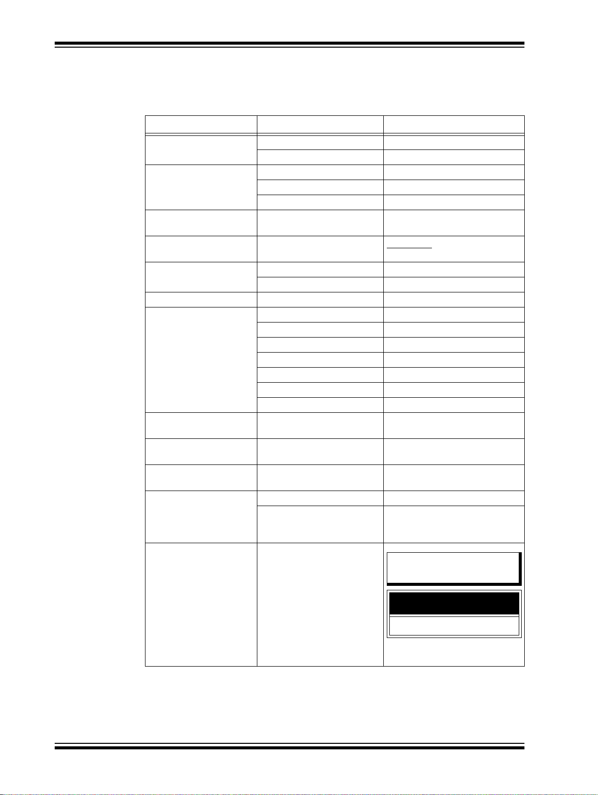
CONVENTIONS USED IN THIS GUIDE
This manual uses the following docume ntatio n conv en tion s:
DOCUMENTATION CONVENTIONS
Description Represents Examples
Italic characters Referenced books MPLAB IDE User’s Guide
Emphasized text ...is the only compiler...
Initial caps A window the Output window
A dialog the Setti ngs dialog
A menu selection select Enable Programmer
Quotes A field name in a window or
dialog
Underlined, italic text with
right angle bracket
Bold characters A dialog button Click OK
Text in angle brackets < > A key on the keyboard Press <Enter>, <F1>
Plain Courier New Sample source code #define START
Italic Courier New A variable argument file.o, where file can be any
Square brackets [ ] Optional arguments mcc18 [options] file
Curly brackets and pipe
character: { | }
Ellipses... Replaces repeated text var_name [, var_name...]
Notes
A menu path File > Save
A tab Click the Power tab
Filenames autoexec.bat
File paths c:\mcc18\h
Keywords _asm, _endasm, static
Command-line options -Opa+, -Opa-
Bit values 0, 1
Constants 0xFF, ‘A’
Choice of mutually exclusive
arguments; an OR selection
Represents code supplied by
user
A Note presents information
that we want to re-emphasize,
either to help you avoid a
common pitfa ll or to m ake you
aware of operating di fferences
between some device family
members. A Note can be in a
box, or when used in a table
or figure, it is located at the
bottom of the table or figure.
“Save project before build”
valid filename
[options]
errorlevel {0|1}
void main (void)
{ ...
}
DS70005235C-Page 8 2015-2016 Microchip Technology Inc.
Page 9

RECOMMENDED READING
This user’s guide describes how to use the BM70 EVB. The following Microchip
document is available and recommended as supplemental reference resources.
BM70/BM71 Data Sheet (DS60001372)
Refer to this document for detailed information on the BM70 module. The reference
information found in this data sheet includes:
• Features and pin configurations
• Electrical s pecifications
• Reference circuits
THE MICROCHIP WEB SITE
Microchip provides online support via our web site at: http://www.microchip.com. This
web site makes files and information easily available to customers. Accessible by most
Internet browsers, the web site contains the following information:
• Product Support – Data sheets and errata, application notes and sample
programs, design resources, user’s guides and hardware support documents,
latest software releases and archived software
• General Technical Support – Frequently Asked Questions (FAQs), technical
support requests, online discussion groups, Microchip consultant program
member listings
• Business of Microchip – Product selector and ordering guides, latest Microchip
press releases, listings of seminars and events; and listings of Microchip sales
offices, distributors and factory representatives
Preface
2015-2016 Microchip Technology Inc. DS70005235C-P age 9
Page 10

BM70 PICtailTM/PICtail Plus EVB User’s Guide
DEVELOPMENT SYSTEMS CUSTOMER CHANGE NOTIFICATION SERVICE
Microchip’s customer notification service helps keep customers current on Microchip
products. Subscribers will receive email notification whenever there are changes,
updates, revisions or errata related to a specified product family or development tool of
interest.
To register, access the Microchip web site at www.microchip.com, click on Customer
Change Notification and follow the registration instructions.
The Development Systems product group categories are:
• Compilers – The latest info rmat ion on Mi croc hip C com pile rs an d ot her l ang uage
tools
• Emulators – The latest information on the Microchip in-circuit emulator, MPLAB
REAL ICE™
• In-Circuit Debuggers – The latest information on the Microchip in-circuit
debugger, MPLAB ICD 3
• MPLAB X IDE – The latest information on Microchip MPLAB X IDE, the
Windows
• Programmers – The latest information on Microchip programmers including the
PICkit™ 3 development programmer
®
Integrated Development Environment for development systems tools
CUSTOMER SUPPORT
Users of Microchip products can receive assistance through several channels:
• Distributor or Representative
• Local Sales Office
• Field Application Engi neer (FAE)
• Technical Support
Customers should contact their distributor, representative or Field Application Engineer
(FAE) for support. Local sales offices are also available to help customers. A listing of
sales offices and locations is included in the back of this document.
Technical support is available through the web site at: http://support.microchip.com.
DS70005235C-Page 10 2015-2016 Microchip Technology Inc.
Page 11

DOCUMENT REVISION HISTORY
Revision A (October 2015)
This is the initial released version of this document.
Revision B (October 2015)
This revision includes the following updates:
• Added Figure 2-1, Table 2-1 through Table 2-10
• Updated Figure A-1
Minor updates to text and formatting were incorporated throughout the document.
Revision C (May 2016)
This revision includes the following updates:
• Updated Chapter 3. “Getting Started”
• Updated Chapter 4. “Flash Programming Procedure”
• Updated Chapter 5. “USB-to-UART Converter and Host DUT”
• Updated Appendix A. “Schematics”
Minor updates to text and formatting were incorporated throughout the document.
Preface
2015-2016 Microchip Technology Inc. DS70005235C-Page 11
Page 12

BM70 PICtailTM/PICtail Plus EVB User’s Guide
NOTES:
DS70005235C-Page 12 2015-2016 Microchip Technology Inc.
Page 13
Thank you for purchasing a Microchip T echnology BM70 PICtail™/PICtail Plus Evaluation Board (EVB). This document provides detailed information about the BM70 EVB.
The BM70 EVB is designed to evaluate and demonstrate the capabilities of the
Microchip BM70 BLE module.
This chapter includes the following topics:
1.1 “Kit Contents”
1.2 “BM70 EVB Features”
The BM70 EVB can be evaluated using various tools which are listed on the pr oduct
page of the Microchip worldwide web site: http:// www.microchip.com/bm-70-pictail.
1.1 KIT CONTENTS
The BM70 EVB kit contains these items:
• One BM70 EVB, which contains the BM70BLES1FC2 module
• One micro-USB cable
BM70 PICTAILTM/PICTAIL PLUS
EVB USER’S GUIDE
Chapter 1. Introduction
Note: If you are missing any part of the kit, contact a Microchip sales office for
assistance. A list of Microchip offices for sales and service is provided on
the back page of this document.
1.2 BM70 EVB FEATURES
The following are key features of the BM70 EVB:
• Option to switch power source between the Coin Cell battery, USB, and PICtail
interface
• The UART interface to connect to an external MCU
• Connection and test interface between the BM70 module and Host Emulator tool
on the PC (with UART commands)
• Ability to update the firmware using the micro-USB port
• Switch between Application mode and Test mode
• LED, push button, I
2
C and SPI interface
2015-2016 Microchip Technology Inc. DS70005235C-Page 13
Page 14
BM70 PICtailTM/PICtail Plus EVB User’s Guide
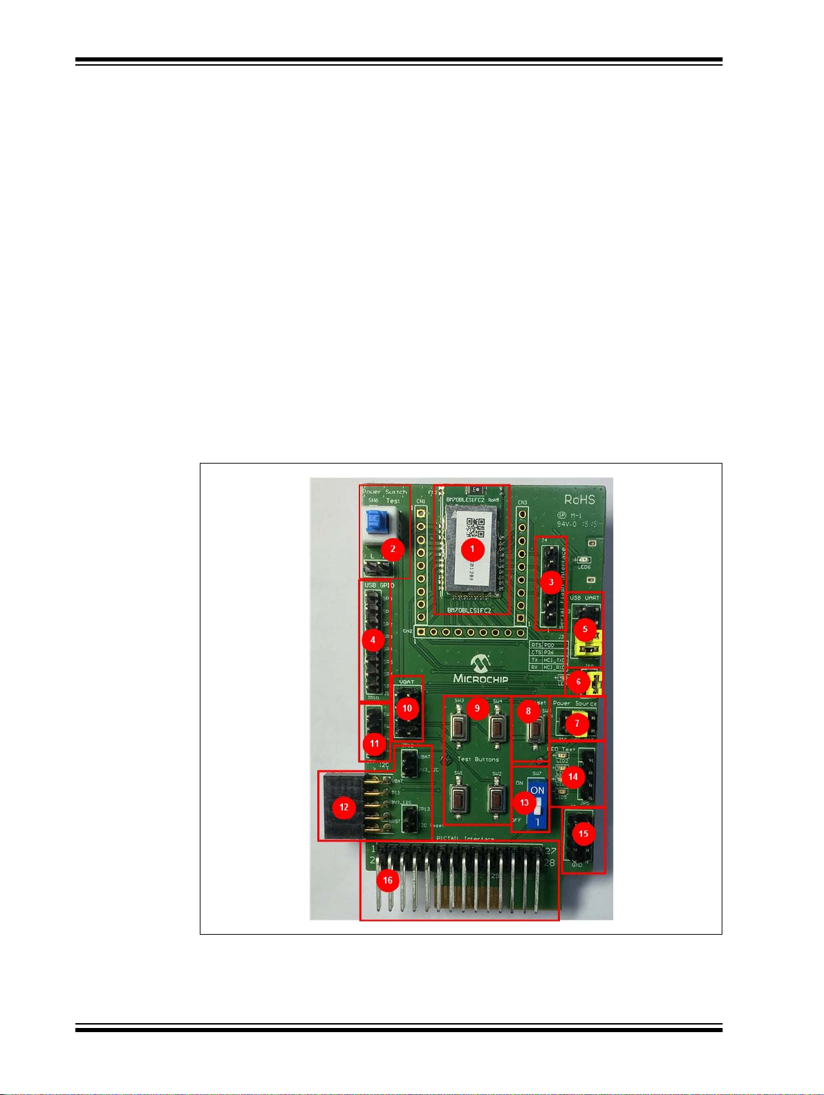
Representation of the layout of the BM70 EVB are illustrated in Figure 1-1 and Figure 1-2.
The top view of the board includ es the following key features as indicated in Figure 1-1.
1. The B M7 0B LES 1FC2 modul e
2. Power switch button (SW6)
3. SPI interface (J4)
4. USB GPIO interface (JP10)
5. USB-to-UART interface (J3)
6. LED
7. Power source connector (J1)
8. Reset bu tto n (S W5)
9. Test buttons (Push-low)
10. V
BAT
header pins (J10)
11. Test button header (J7)
2
12. I
C interface (JP12, JP13)
13. DIP switch (SW7)
14. LEDs and corresponding header pins (JP5)
15. GND header pins (J2)
16. PICtail interface (J8)
FIGURE 1-1: BM70 EVB (TOP VIEW)
DS70005235C-Page 14 2015-2016 Microchip Technology Inc.
Page 15
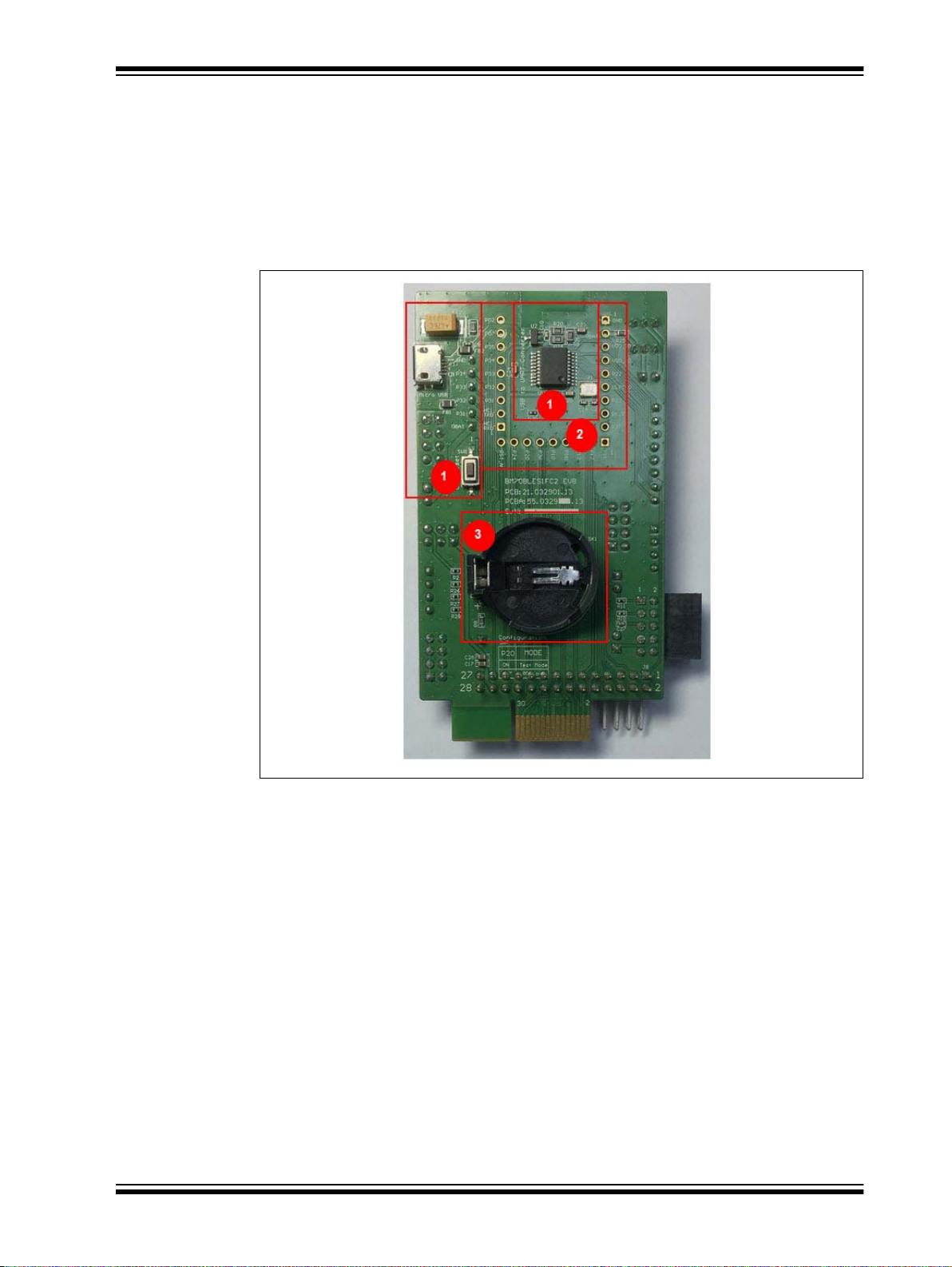
Introduction
Figure 1-2 illustrates the bottom view of the BM70 EVB with the following key
components:
1. USB-to-UART converter. The switch SW8 is the USB Reset button
2. Module pads
3. Coin Cell battery holder
For additional information on these features, refer to Chapter 2. “Hardware”.
FIGURE 1-2: BM70 EVB (BOTTOM VIEW)
2015-2016 Microchip Technology Inc. D S70005235C-Page 15
Page 16

BM70 PICtailTM/PICtail Plus EVB User’s Guide
NOTES:
DS70005235C-Page 16 2015-2016 Microchip Technology Inc.
Page 17

BM70 PICTAILTM/PICTAIL PLUS
EVB USER’S GUIDE
Chapter 2. Hardware
This chapter describes the hardware features of the BM70 EVB. The BM70 EVB
provides many options for connecting and communicating with other peripheral
devices and power sources as illustrated in Figure 2-1.
FIGURE 2-1: BM70 EVB BLOCK DIAGRAM
2.1 HARDWARE FEATURES
The following sections provide the details of each component in the BM70 EVB, and
for their location on the board, refer to Figure 1-1 and Figure 1-2.
2.1.1 Power Supply
There are three ways to supply power to theBM70 EVB:
• Coin Cell battery (socket SK1 for CR2032 battery)
•USB
• PICtail socket connection
2.1.2 USB connectivity
The BM70 EVB provides micro-USB cable connectivity.
2015-2016 Microchip Technology Inc. DS70005235C-Page 17
Page 18

BM70 PICtailTM/PICtail Plus EVB User’s Guide
2.1.3 Switches
Push button switches provide the following functionality:
• SW1, SW2, SW3 and SW4 – Test buttons, available for evaluation and are
connected to the corresponding header pins
• SW5 – Reset button, connects to the Reset pin (pin 21) of the module
• SW6 – Power switch button, includes Push-High and Push-Low header
• SW7 – DIP switch to switch between Application and Test modes
• SW8 – USB Reset button
2.1.4 LEDs
The functionality of the six LEDs are as follows:
• LED1 – Connected to the P0_2 pin (pin 30) of the BM70 module, which provides
the module status
• LED2, LED3, LED4 and LED5 – Configurable test LEDs for diagnostics. These
LEDs have header connections which can be connected for testing
• LED6 – USB connection indicator. This LED will turn ON when USB 5V input is
connected
2.1.5 Jumpers
There are 12 jumpers (J1, J2, J3, J4, J5, J10, JP6, JP7, JP8, JP10, JP12 and JP13)
available on the BM70 EVB. Table 2-1 through Table 2-12 provide the details of the
pins and signals that are associated with the jumpers.
TABLE 2-1: POWER SOURCE OPTION CONNECTOR
Part
Number
J1 1 PIC_3V3 Power source from PICtail 3.3V, enabled by pin 2 in
Pin Signal Description
the jumper bank J1
2V
3 USB_3V3 Power source from USB enabled by pin 4 on the
4V
5 BAT Power source from Coin Cell Battery, enabled by pin
6V
BAT
BAT
BAT
BM70 power source input
jumper bank J1 . The po wer in put is sent t o 3. 3V LDO
to provide the module with a 3.3V input
BM70 power source input
6 on the jumper bank J1
BM70 power source input
TABLE 2-2: GROUND TEST CONNECTOR
Part
Number
J2 1 to 8 GND Ground test pins
Pin Signal Description
DS70005235C-Page 18 2015-2016 Microchip Technology Inc.
Page 19

TABLE 2-3: USB TO UART INTERFACE U10
Part
Number
J3 1 RTS MCP2200 RTS pin
Pin Signal
2 P0_0 BM70 GPIO P0_0 (Pin 15)
Configured as CTS and co nne cted to J3 pin1 by the
jumper
3 CTS MCP2200 CTS pin
4 P3_6 BM70 GPIO P3_6 (pin 17)
Configured as RTS and co nnected to J3 pin 3 by the
jumper
5 TX MCP2200 RX pin
6 HCI_TXD BM70 HCI_TXD (pin 23)
Connected to J3 pin 5 by the jumper
7 RX MCP2200 TX pin
8 HCI_RXD BM70 HCI_RXD (pin 22)
Connected to J3 pin 7 by the jumper
TABLE 2-4: SERIAL FLASH INTERFACE
Part
Number
J4 1 V
Pin Signal
BAT
BM70 power source input
2 P3_1 Configured as SPI_NCS
3 P3_2 Configured as SPI_MISO
4 P3_3 Configured as SPI_MOSI
5 P3_4 Configured as SPI_SCLK
6 GND Ground pin
Hardware
Description
Description
TABLE 2-5: VBAT TEST CONNECTOR
Part
Number
Pin Signal
J10 1 to 8 V
BAT
V
BAT
test pins
Description
TABLE 2-6: CONNECTOR J10
Part
Number
Pin Signal
JP10 1 to 8 GP0 to GP7 MCP2200 GPIOs
Description
TABLE 2-7: CONNECTOR JP12
Part
Number
Pin Signal
JP12 1 V
23V3_I
BAT
V
BAT
test pin
2
C 3V3 voltage of I2C interface, short to V
age supply
Description
Note: The jumper JP12 must be connected as a default jumper.
BAT
for volt-
2015-2016 Microchip Technology Inc. D S70005235C-Page 19
Page 20

BM70 PICtailTM/PICtail Plus EVB User’s Guide
TABLE 2-8: CONNECTOR JP13
Part
Number
JP13 1 nRST
Pin Signal
2
C (device) Reset pin, wire connect to the config-
I
ured GPIO Reset pin
2 NC No connect
TABLE 2-9: CONNECTOR J5
Part
Number
J5 1 to 4 LED2 to
Pin Signal
LED5
Test LED interface (Pull-Low enable), wire connect to test the GPIO pin
TABLE 2-10: CONNECTOR JP6
Part
Number
JP6 1 Push-High Latching switch SW6, Push-High test pin, wire
Pin Signal
connect to test GPIO
2 Push-Low Latching switc h SW 6, Push -L ow te st p in, wire c on -
nect to test GPIO
Description
Description
Description
TABLE 2-11: CONNECTOR JP7
Part
Number
JP7 1 to 4 SW1 to
Pin Signal
SW4
Push-Low test buttons, wire connect to test GPIO
Description
TABLE 2-12: CONNECTOR JP8
Part
Number
JP8 1 LED Connected to status LED (LED1)
Pin Signal
2V
BAT
Power source of LED1, short to JP8 pin1 to enable
the status LED f unction
Description
DS70005235C-Page 20 2015-2016 Microchip Technology Inc.
Page 21

This chapter describes how to update UI parameters and setting up the connection
between the BM70 EVB and a smartphone using the BLE link.
This chapter includes the following topics:
3.1 “Requirements”
3.2 “Configuring UI Parameters”
3.3 “BLE Connection to Smartphone”
3.4 “BLEDK3 Auto Pattern and Manual Pattern Tools”
3.5 “Application Firmware Information”
3.1 REQUIREMENTS
The following hardware and software are required for getting started with the BM70
EVB.
3.1.1 Hardware Requirements
BM70 PICTAILTM/PICTAIL PLUS
EVB USER’S GUIDE
Chapter 3. Getting Started
•One BM70 EVB
• Any one of these Bluetooth-enabled smartphone
- iPhone
- Android™ device running on Android 4.3 or la ter version
• One Windows
• One micro-USB cable
®
4S or later version (it must support BLE)
®
host PC with USB port
3.1.2 Software Requirements
Users can download the latest firmware and corresponding tools for the following applications, which are available for download from the Microchip web site: www.micro-
chip.com/bm-70-pictail.
• Firmware update tool, isupdate.v4.0.0.207.rar
• BLEDK3 Flash code, BT5505_BLEDK3_v103_c1457.rar
• BLEDK3 UI tool, IS187x_102_BLEDK3_UI v100.123.rar
• mBIoT Utility app, available at App Store
store for Android
for iPhone and at Google Play™
2015-2016 Microchip Technology Inc. DS70005235C-Page 21
Page 22

BM70 PICtailTM/PICtail Plus EVB User’s Guide
3.2 CONFIGURING UI PARAMETERS
The UI configuration tool enables the user to change the BM70 EVB parameters, such
as device name, UART settings, BLE connection settings, adding or editing GATT service table.
To update UI parameters, perform these actions:
1. Double-click the IS187x_102_BLEDK3_UI_Configuration_Tool.exe to
open the BLEDK3 UI configuration tool on the PC. The UI Configuration tool window is displayed.
2. Click Load, see Figure3-1. The Loading Option window is displayed.
Note: Download and install the UI configuration tool, which is available for
download from the Microchip web site: www.microchip.com/bm-70-pictail.
In this demonstration, the IS187x_102_BLEDK3_UI_Configuration_Tool
v100.123 tool is used. This UI tool version corresponds to the firmware
version of the “BLEDK3 v1.03”.
FIGURE 3-1: BLEDK3 UI CONFIGURATION TOOL WINDOW
DS70005235C-Page 22 2015-2016 Microchip Technology Inc.
Page 23

Getting Started
3. In the Loading Option window, click Load Text File to load UI parameters, see
Figure 3-2.
FIGURE 3-2: LOADING OPTION WINDOW
4. From the Open dialog, select the default UI parameter text file (provided with the
UI tool) and then click Open, see Figure 3-3.
FIGURE 3-3: OPEN DIALOG BOX
2015-2016 Microchip Technology Inc. D S70005235C-P age 23
Page 24

BM70 PICtailTM/PICtail Plus EVB User’s Guide
5. From the UI Configuration Tool window, select UI parameters, and then click
Edit, see Figure 3-4.
FIGURE 3-4: UI CONFIGURATION TOOL WINDOW
6. From the Main Feature window, click BLEDK and then click OK, see
Figure 3-5.
FIGURE 3-5: MAIN FEATURE WINDOW
DS70005235C-Page 24 2015-2016 Microchip Technology Inc.
Page 25

Getting Started
7. The UI Configuration Tool dialog has various tabs to configure UI parameters.
Click the System Setup tab, and in the Name fragment box, type BM70_BLE
(or any user-defined name), see Figure 3-6.
Note: Click Help button to get the information related to UI parameters.
FIGURE 3-6: CONFIGURING UI PARAMETERS - SYSTEM SETUP
2015-2016 Microchip Technology Inc. D S70005235C-P age 25
Page 26

BM70 PICtailTM/PICtail Plus EVB User’s Guide
8. Click the LE Mode Setup tab, and under the Advertising Data Setting section,
select Device Name to advertise the device name, see Figure 3-7.
FIGURE 3-7: ADVERTISING DATA SETTING
DS70005235C-Page 26 2015-2016 Microchip Technology Inc.
Page 27

Getting Started
9. Click Finish. The UI Configuration Tool window is displayed, see Figure 3-8.
FIGURE 3-8: UI CONFIGURATION TOOL WINDOW
10. From the UI Configuration Tool window, perform any one of these actions:
-Click Save to save the selected UI parameters as .
production)
-Click Export to export the UI log
ters and setup values
-Click Write to download UI parameters to Flash
11. To write UI parameters on the BM70 module, perform these actions:
a) Set the switch SW7 in the ON position (Test mode), see Figure 3-9.
FIGURE 3-9: SW7 IN TEST MODE
.txt
file. The log file contains the parame-
txt or .hex
files (for mass
2015-2016 Microchip Technology Inc. D S70005235C-P age 27
Page 28

BM70 PICtailTM/PICtail Plus EVB User’s Guide
b) Ensure that the jumpers, J1, JP8 and J3, on the BM70 EVB are connected,
as shown in Figure 3-10.
FIGURE 3-10: JUMPER AND BM70 EVB CONNECTION DETAILS
c) Connect the USB port (P1) of the BM70 EVB to a PC using the micro-USB
cable, see Figure 3-11.
FIGURE 3-11: UI CONFIGURATION SETUP
d) On connection, LED1 (blue) and LED6 (red) on the BM70 EVB will turn ON.
e) Go to the UI Configuration Tool window, and click Write to download UI
parameters on the BM70 module, see Figure 3-8.
DS70005235C-Page 28 2015-2016 Microchip Technology Inc.
Page 29

Getting Started
f) The Read/Write Flash window is displayed. Select the values for COM Port
and Baudrate, and then click Write, se e Figure 3-12.
FIGURE 3-12: READ/WRITE FLASH
g) A message box will appear displaying the message “Write Flash Finish”.
Click OK to download UI parameters, see Figure 3-13.
FIGURE 3-13: MESSAGE BOX
2015-2016 Microchip Technology Inc. D S70005235C-P age 29
Page 30

BM70 PICtailTM/PICtail Plus EVB User’s Guide
3.3 BLE CONNECTION TO SMARTPHONE
Perform the following actions to establish a BLE connection between the BM70 EVB
and a smartphone. An iPhone with iOS9.2.1 is used for this demonstration.
1. Set the switch SW7 to the OFF position (Application mode) on the BM70 EVB,
see Figure 3-14.
FIGURE 3-14: SW7 IN APPLICATION MODE
2. Connect the BM70 EVB to a PC using the micro-USB cable, see Figure 3-15.
Press the Reset button (SW5) to reset the BM70 EVB. On connection, LED6
(red) will turn ON and LED1 (blue) blinks once at an interval.
FIGURE 3-15: POWER ON BM70 EVB
DS70005235C-Page 30 2015-2016 Microchip Technology Inc.
Page 31

Getting Started
3. Download the mBIoT app from the App Store and enable the Bluetooth settings
on the iPhone, see Figure 3-16.
FIGURE 3-16: ENABLING BLUETOOTH AND MBIOT APPLICATION
2015-2016 Microchip Technology Inc. D S70005235C-P age 31
Page 32

BM70 PICtailTM/PICtail Plus EVB User’s Guide
4. Tap mBIoT app and then tap to open the BM70 BLE UART, see Figure 3-17.
FIGURE 3-17: SELECT BM70 BLE UART
5. A list of discoverable devices will be displayed, tap on the BM70_BLE to connect, see Figure 3-18.
FIGURE 3-18: DISCOVERED DEVICES VIEW
DS70005235C-Page 32 2015-2016 Microchip Technology Inc.
Page 33

Getting Started
6. Under Connected Device, tap BM70_BLE connected to get the device
information, see Figure 3-19
FIGURE 3-19: CONNECTED DEVICE VIEW
7. Tap Device Info to check the device information, see Figure 3-20.
FIGURE 3-20: DEVICE INFORMATION
2015-2016 Microchip Technology Inc. D S70005235C-P age 33
Page 34

BM70 PICtailTM/PICtail Plus EVB User’s Guide
8. The device information will be displayed, see Figure 3-21.
FIGURE 3-21: DEVICE INFORMATION
9. The BLE link is established between the BM70 EVB and an iPhone, see
Figure 3-22.
FIGURE 3-22: BLE LINK CONNECTION
DS70005235C-Page 34 2015-2016 Microchip Technology Inc.
Page 35

Getting Started
3.4 BLEDK3 AUTO PATTERN AND MANUAL PATTERN TOOLS
The BLEDK3 firmware, written on the BM70 module, has two distinct modes, Auto Pattern and Man ua l Pa tt e rn . B o t h t h ese mo des use their o wn s tate machines. The BM 70
module can be operated in both the modes by setting the value in the EEPROM. By
default, the BM70 module is in Auto Pattern mode.
3.4.1 Auto Pattern Mode
In Auto pattern mode, the state machine automates most of the Bluetooth related operations, su ch as advertising and Transp arent UART service. The Transparent UART
service is primarily used to connect the module to a peer device and to create a data
pipe with the peer device through the Transparent UART mode with minimal instructions from the host MCU.
To evaluate and test the BM70 module in Auto Pattern mode, download and install the
Auto Pattern tool (Windows-based GUI emulation tool), which is available for download
at Microchip web site. This tool implements the communication protocol and provides
a fast and easy way to test the functions with the available options in the Auto Pattern
mode.
3.4.2 Manual Pattern Mode
The Manual Pattern mode provides a full control of the BM70 module to the user and
the module operates only based on the commands from the user or host MCU. The
Manual Pattern tool also allows the Transparent UART mode; however, there is a small
difference in the protocol used in this mode in comparison to the Auto Pattern mode.
To evaluate and test the BM70 module in Manual Pattern mode, download and install
the Manual Pattern tool (Windows-based GUI emulation tool), which is available for
download at Microchip web site. This tool implements the communication protocol and
provides a fast and easy way to test the functions with the available options in the Manual Pattern mode.
Note: For more information on Auto Pattern and Manual Pattern tools, refer to the
“IS187x_BM7x BLEDK3 Application Note”, which is avai la bl e at M icr ochip
web site: www.microchip. com/bm-70-pictail.
3.5 APPLICATION FIRMWARE INFORMATION
The BLEDK3 firmware application is the default application on the BM70 EVB. This
application provides the BLE UART Transparent, BLE GATT-based transceiver, Beacon and BeaconThings functionality.
For additional information on the BLEDK3 application functionality, refer to the
“IS187x_BM7x BLEDK3 Application Note”, which is available at Microchip web site:
www.microchip.com/bm-70-pictail.
2015-2016 Microchip Technology Inc. D S70005235C-P age 35
Page 36

BM70 PICtailTM/PICtail Plus EVB User’s Guide
NOTES:
DS70005235C-Page 36 2015-2016 Microchip Technology Inc.
Page 37

BM70 PICTAILTM/PICTAIL PLUS
Chapter 4. Flash Programming Procedure
This chapt er describes the process of downloading the firmware to the B M70 module.
4.1 FLASH PROGRAMMING PROCEDURE
Flash programming is required to update a newer or specific version of the firmware.
Perform the following actions for Flash programming:
1. Set the switch SW7 in the ON position (Test mode), see Figure 4-1.
FIGURE 4-1: SW7 IN TEST MODE
EVB USER’S GUIDE
2. Ensure that the jumpers, J1, JP8 and J3, on the BM70 EVB are connected, as
illustrated in Figure 3-10.
3. Connect the BM70 EVB to a PC using the micro-USB cable, see Figure 4-2. On
connection, LED6 (red) and LED1 (blue) will turn on. Press the Reset button
(SW5) to reset the BM70 module.
FIGURE 4-2: FLASH PROGRAMMING SETUP
2015-2016 Microchip Technology Inc. DS70005235C-Page 37
Page 38

BM70 PICtailTM/PICtail Plus EVB User’s Guide
4. Download and install the isupdate.exe file, which is available for download
from the Microchip web site: www.microchip.com/bm-70-pictail.
5. Double-click th e isupdate.exe file to open the firmware update tool on the PC.
6. Click Connect after setting these parameters.
-Port
- Baud Rate: 115200
- Memory type/subtype: Flash/Embedded Flash
- Address: 0000
On successful connection, “Port connect -> Port Number” message will be displayed,
see Figure 4-3.
FIGURE 4-3: FIRMWARE UPDATE TOOL WINDOW - PO RT CONNECT
DS70005235C-Page 38 2015-2016 Microchip Technology Inc.
Page 39

Flash Programming Procedure
7. If the connection is failed, “Connect failed” message will be displayed. Verify the
parameters and try connecting it again, see Figure 4-4.
FIGURE 4-4: FIRMWARE UPDATE TOOL WINDOW
8. Click Browse to display four Flash code files (.hex) downloaded from the
Microchip web site.
2015-2016 Microchip Technology Inc. D S70005235C-P age 39
Page 40

BM70 PICtailTM/PICtail Plus EVB User’s Guide
9. From the Open dialog, select Flash code files and click Open, see Figure 4-5.
Note: In this demonstration, the BLEDK3 v1.03 is used.
FIGURE 4-5: SELECTING FLASH CODE FILES
DS70005235C-Page 40 2015-2016 Microchip Technology Inc.
Page 41

Flash Programming Procedure
10. In the Firmware Update tool window, click Update, see Figure 4-6.
FIGURE 4-6: FIRMWARE UPDATE
2015-2016 Microchip Technology Inc. D S70005235C-P age 41
Page 42

BM70 PICtailTM/PICtail Plus EVB User’s Guide
11. The Firmware Update tool will start writing the Flash codes. Wait until the message “End of Write Memory!” with the elapse time is displayed, see Figure 4-7.
FIGURE 4-7: FIRMWARE UPDATE FINISH
DS70005235C-Page 42 2015-2016 Microchip Technology Inc.
Page 43

Flash Programming Procedure
12. To verify the firmware version, enter the following parameters under the
Flash/EEPROM/ MCU/AHB Access secti on, and then click Read, see Figure 4-8:
- Address: “100e”
- Length (Hex): “02”
FIGURE 4-8: ENTERING PARAMETERS
2015-2016 Microchip Technology Inc. D S70005235C-P age 43
Page 44

BM70 PICtailTM/PICtail Plus EVB User’s Guide
13. The Data (Hex) box will display the value “01 03” along with the related log information, see Figure 4-9.
FIGURE 4-9: DATA (HEX) VALUE
14. After completing the firmware update, reboot the BM70 EVB using the Reset
button (SW5 ).
DS70005235C-Page 44 2015-2016 Microchip Technology Inc.
Page 45

BM70 PICTAILTM/PICTAIL PLUS
EVB USER’S GUIDE
Chapter 5. USB-to-UART Converter and Host DUT
This chapter describes the use of the USB-to-UART converter circuit which is available
on the BM70 E VB. The UAR T int erf ace of t he BM7 0 mod ule on the BM70 EVB can be
connected to the user DUT. The DUT can be a customer board with a host
microcontroller or another BM70 EVB.
5.1 CONNECTING UART TO BM70 EVB DUT
The BM70 EVB has a MCP2200 IC acting as a USB-to-UART converter that connects
the BM70 module to the micro-USB port. The BM70 EVB also has a range of header
pins that connect to the UART I/O pins of the BM70 module. This gives the flexibility to
connect the USB-to-UART converter on the BM70 EVB to another BM70 DUT, or
connect the BM70 EVB test pins directly to another host microcontroller DUT.
Figure 5-1 illustrates how to connect the USB-to-UART converter on the BM70 EVB to
the user BM70 DUT. The pins, HCI_TXD, HCI_RXD, P2_0, V
connected to the DU T. The user ca n co n ne ct a mi cr o- U SB ca b le to a P C an d pe rf o rm
the emula tion tool functio ns, such as firmwar e or UI upd ate. The P2_ 0 pin is c onnected
to the switch SW7 to switch between Application and Test modes.
BAT
, GPIO and GND, are
FIGURE 5-1: UART CONNECTION TO BM70 EVB DUT
2015-2016 Microchip Technology Inc. DS70005235C-Page 45
Page 46

BM70 PICtailTM/PICtail Plus EVB User’s Guide
5.2 CONNECTING UART TO H OST MICROCONTROLLER DUT
Figure 5-2 illustrates how to connect a user microcontroller DUT to a BM70 EVB to per-
form the emulation tool function. The pins, HCI_TXD, HCI_RXD, P2_0, V
GPIO, and GND, are connected to the DUT. In this connection, the microcontroller can
communicate with the BM70 EVB through the HCI UART interface by a defined command set. The P2_0 pin is controlled by the MCU to switch between Application and
Test modes.
FIGURE 5-2: UART CONNECTION TO HOST MICROCONTROLLER DUT
BAT
, RESET ,
DS70005235C-Page 46 2015-2016 Microchip Technology Inc.
Page 47

Appendix A. Schematics
A.1 REFERENCE SCHEMATICS
FIGURE A-1: BM70 EVB SCHEMATIC S
BM70 PICTAILTM/PICTAIL PLUS
EVB USER’S GUIDE
2015-2016 Microchip Technology Inc. DS70005235C-Page 47
Page 48

BM70 PICtailTM/PICtail Plus EVB User’s Guide
FIGURE A-2: BM70 EVB SCHEMATICS
DS70005235C-Page 48 2015-2016 Microchip Technology Inc.
Page 49

NOTES:
2015-2016 Microchip Technology Inc. D S70005235C-Page 49
Page 50

Worldwide Sales and Service
AMERICAS
Corporate Office
2355 West Chandler Blvd.
Chandler, AZ 85224-6199
Tel: 480-792-7200
Fax: 480-792-7277
Technical Support:
http://www.microchip.com/
support
Web Address:
www.microchip.com
Atlanta
Duluth, GA
Tel: 678-957-9614
Fax: 678-957-1455
Austin, TX
Tel: 512-257-3370
Boston
Westborough, MA
Tel: 774-760-0087
Fax: 774-760-0088
Chicago
Itasca, IL
Tel: 630-285-0071
Fax: 630-285-0075
Cleveland
Independence, OH
Tel: 216-447-0464
Fax: 216-447-0643
Dallas
Addison, TX
Tel: 972-818-7423
Fax: 972-818-2924
Detroit
Novi, MI
Tel: 248-848-4000
Houston, TX
Tel: 281-894-5983
Indianapolis
Noblesville, IN
Tel: 317-773-8323
Fax: 317-773-5453
Los Angeles
Mission Viejo, CA
Tel: 949-462-9523
Fax: 949-462-9608
New York, NY
Tel: 631-435-6000
San Jose, CA
Tel: 408-735-9110
Canada - Toronto
Tel: 905-673-0699
Fax: 905-673-6509
ASIA/PACIFIC
Asia Pacific Office
Suites 3707-14, 37th Floor
Tower 6, The Gateway
Harbour City, Kowloon
Hong Kong
Tel: 852-2943-5100
Fax: 852-2401-3431
Australia - Sydney
Tel: 61-2-9868-6733
Fax: 61-2-9868-6755
China - Beijing
Tel: 86-10-8569-7000
Fax: 86-10-8528-2104
China - Chengdu
Tel: 86-28-8665-5511
Fax: 86-28-8665-7889
China - Chongqing
Tel: 86-23-8980-9588
Fax: 86-23-8980-9500
China - Dongguan
Tel: 86-769-8702-9880
China - Hangzhou
Tel: 86-571-8792-8115
Fax: 86-571-8792-8116
China - Hong Kong SAR
Tel: 852-2943-5100
Fax: 852-2401-3431
China - Nanjing
Tel: 86-25-8473-2460
Fax: 86-25-8473-2470
China - Qingdao
Tel: 86-532-8502-7355
Fax: 86-532-8502-7205
China - Shanghai
Tel: 86-21-5407-5533
Fax: 86-21-5407-5066
China - Shenyang
Tel: 86-24-2334-2829
Fax: 86-24-2334-2393
China - Shenzhen
Tel: 86-755-8864-2200
Fax: 86-755-8203-1760
China - Wuhan
Tel: 86-27-5980-5300
Fax: 86-27-5980-5118
China - Xian
Tel: 86-29-8833-7252
Fax: 86-29-8833-7256
ASIA/PACIFIC
China - Xiamen
Tel: 86-592-2388138
Fax: 86-592-2388130
China - Zhuhai
Tel: 86-756-3210040
Fax: 86-756-3210049
India - Bangalore
Tel: 91-80-3090-4444
Fax: 91-80-3090-4123
India - New Delhi
Tel: 91-11-4160-8631
Fax: 91-11-4160-8632
India - Pune
Tel: 91-20-3019-1500
Japan - Osaka
Tel: 81-6-6152-7160
Fax: 81-6-6152-9310
Japan - Tokyo
Tel: 81-3-6880- 3770
Fax: 81-3-6880-3771
Korea - Daegu
Tel: 82-53-744-4301
Fax: 82-53-744-4302
Korea - Seoul
Tel: 82-2-554-7200
Fax: 82-2-558-5932 or
82-2-558-5934
Malaysia - Kuala Lumpur
Tel: 60-3-6201-9857
Fax: 60-3-6201-9859
Malaysia - Penang
Tel: 60-4-227-8870
Fax: 60-4-227-4068
Philippines - Manila
Tel: 63-2-634-9065
Fax: 63-2-634-9069
Singapore
Tel: 65-6334-8870
Fax: 65-6334-8850
Taiwan - Hsin Chu
Tel: 886-3-5778-366
Fax: 886-3-5770-955
Taiwan - Kaohsiung
Tel: 886-7-213-7828
Taiwan - Taipei
Tel: 886-2-2508-8600
Fax: 886-2-2508-0102
Thailand - Bangkok
Tel: 66-2-694-1351
Fax: 66-2-694-1350
EUROPE
Austria - Wels
Tel: 43-7242-2244-39
Fax: 43-7242-2244-393
Denmark - Copenhagen
Tel: 45-4450-2828
Fax: 45-4485-2829
France - Paris
Tel: 33-1-69-53-63-20
Fax: 33-1-69-30-90-79
Germany - Dusseldorf
Tel: 49-2129-3766400
Germany - Karlsruhe
Tel: 49-721-625370
Germany - Munich
Tel: 49-89-627-144-0
Fax: 49-89-627-144-44
Italy - Milan
Tel: 39-0331-742611
Fax: 39-0331-466781
Italy - Venice
Tel: 39-049-7625286
Netherlands - Drunen
Tel: 31-416-690399
Fax: 31-416-690340
Poland - Wars a w
Tel: 48-22-3325737
Spain - Madrid
Tel: 34-91-708-08-90
Fax: 34-91-708-08-91
Sweden - Stockholm
Tel: 46-8-5090-4654
UK - Wokingham
Tel: 44-118-921-5800
Fax: 44-118-921-5820
07/14/15
DS70005235C-Page 50 2015-2016 Microchip Technology Inc.
 Loading...