

Page 1
Audio Development Board
User’s Guide
© 2011 Microchip Technology Inc. DS70662A
Page 2
Note the following details of the code protection feature on Microchip devices:
• Microchip products meet the specification contained in their particular Microchip Data Sheet.
• Microchip believes that its family of products is one of the most secure families of its kind on the market today, when used in the
intended manner and under normal conditions.
• There are dishonest and possibly illegal methods used to breach the code protection feature. All of these methods, to our
knowledge, require using the Microchip products in a manner outside the operating specifications contained in Microchip’s Data
Sheets. Most likely, the person doing so is engaged in theft of intellectual property.
• Microchip is willing to work with the customer who is concerned about the integrity of their code.
• Neither Microchip nor any other semiconductor manufacturer can guarantee the security of their code. Code protection does not
mean that we are guaranteeing the product as “unbreakable.”
Code protection is constantly evolving. We at Microchip are committed to continuously improving the code protection features of our
products. Attempts to break Microchip’s code protection feature may be a violation of the Digital Millennium Copyright Act. If such acts
allow unauthorized access to your software or other copyrighted work, you may have a right to sue for relief under that Act.
Information contained in this publication regarding device
applications and the like is provided only for your convenience
and may be superseded by updates. It is your responsibility to
ensure that your application meets with your specifications.
MICROCHIP MAKES NO REPRESENTATIONS OR
WARRANTIES OF ANY KIND WHETHER EXPRESS OR
IMPLIED, WRITTEN OR ORAL, STATUTORY OR
OTHERWISE, RELATED TO THE INFORMATION,
INCLUDING BUT NOT LIMITED TO ITS CONDITION,
QUALITY, PERFORMANCE, MERCHANTABILITY OR
FITNESS FOR PURPOSE. Microchip disclaims all liability
arising from this information and its use. Use of Microchip
devices in life support and/or safety applications is entirely at
the buyer’s risk, and the buyer agrees to defend, indemnify and
hold harmless Microchip from any and all damages, claims,
suits, or expenses resulting from such use. No licenses are
conveyed, implicitly or otherwise, under any Microchip
intellectual property rights.
Trademarks
The Microchip name and logo, the Microchip logo, dsPIC,
K
EELOQ, KEELOQ logo, MPLAB, PIC, PICmicro, PICSTART,
32
PIC
logo, rfPIC and UNI/O are registered trademarks of
Microchip Technology Incorporated in the U.S.A. and other
countries.
FilterLab, Hampshire, HI-TECH C, Linear Active Thermistor,
MXDEV, MXLAB, SEEVAL and The Embedded Control
Solutions Company are registered trademarks of Microchip
Technology Incorporated in the U.S.A.
Analog-for-the-Digital Age, Application Maestro, CodeGuard,
dsPICDEM, dsPICDEM.net, dsPICworks, dsSPEAK, ECAN,
ECONOMONITOR, FanSense, HI-TIDE, In-Circuit Serial
Programming, ICSP, Mindi, MiWi, MPASM, MPLAB Certified
logo, MPLIB, MPLINK, mTouch, Omniscient Code
Generation, PICC, PICC-18, PICDEM, PICDEM.net, PICkit,
PICtail, REAL ICE, rfLAB, Select Mode, Total Endurance,
TSHARC, UniWinDriver, WiperLock and ZENA are
trademarks of Microchip Technology Incorporated in the
U.S.A. and other countries.
SQTP is a service mark of Microchip Technology Incorporated
in the U.S.A.
All other trademarks mentioned herein are property of their
respective companies.
© 2011, Microchip Technology Incorporated, Printed in the
U.S.A., All Rights Reserved.
Printed on recycled paper.
ISBN: 978-1-61341-200-8
Microchip received ISO/TS-16949:2002 certification for its worldwide
headquarters, design and wafer fabrication facilities in Chandler and
Tempe, Arizona; Gresham, Oregon and design centers in California
and India. The Company’s quality system processes and procedures
are for its PIC
devices, Serial EEPROMs, microperipherals, nonvolatile memory and
analog products. In addition, Microchip’s quality system for the design
and manufacture of development systems is ISO 9001:2000 certified.
®
MCUs and dsPIC® DSCs, KEELOQ
®
code hopping
DS70662A-page 2 © 2011 Microchip Technology Inc.
Page 3
AUDIO DEVELOPMENT
BOARD USER’S GUIDE
Table of Contents
Preface ........................................................................................................................... 5
Chapter 1. Introduction
1.1 Overview ...................................................................................................... 11
Chapter 2. Hardware
2.1 Power Supply ............................................................................................... 13
2.2 Microcontroller .............................................................................................. 13
2.3 Audio Codec, Microphone and Audio Connections ...................................... 13
2.4 Expansion Connector ................................................................................... 14
2.5 TFT Display .................................................................................................. 14
2.6 USB Connectivity ......................................................................................... 14
2.7 UART Connectivity ....................................................................................... 14
2.8 User LEDs and Switches .............................................................................. 14
Appendix A. Schematics and Board Layout
A.1 Audio Development Board Schematics ....................................................... 15
A.2 Audio Development Board Layout ............................................................... 20
Worldwide Sales and Service .................................................................................... 22
© 2011 Microchip Technology Inc. DS70662A-page 3
Page 4

Audio Development Board User’s Guide
NOTES:
DS70662A-page 4 © 2011 Microchip Technology Inc.
Page 5
AUDIO DEVELOPMENT BOARD
USER’S GUIDE
Preface
NOTICE TO CUSTOMERS
All documentation becomes dated, and this manual is no exception. Microchip tools and
documentation are constantly evolving to meet customer needs, so some actual dialogs
and/or tool descriptions may differ from those in this document. Please refer to our web site
(www.microchip.com) to obtain the latest documentation available.
Documents are identified with a “DS” number. This number is located on the bottom of each
page, in front of the page number. The numbering convention for the DS number is
“DSXXXXXA”, where “XXXXX” is the document number and “A” is the revision level of the
document.
For the most up-to-date information on development tools, see the MPLAB
Select the Help menu, and then Topics to open a list of available on-line help files.
®
IDE on-line help.
INTRODUCTION
This chapter contains general information that will be useful to know before using the
Audio Development Board. Items discussed in this chapter include:
• Document Layout
• Conventions Used in this Guide
• Recommended Reading
• The Microchip Web Site
• Development Systems Customer Change Notification Service
• Customer Support
• Document Revision History
DOCUMENT LAYOUT
This document describes how to use the Audio Development Board as a development
tool to design high-quality audio development platforms.
This user’s guide is composed of the following:
• Chapter 1. “Introduction” – provides an overview of the Audio Development
Board, highlighting its features and uses.
• Chapter 2. “Hardware” – provides the hardware descriptions of the Audio
Development Board.
• Appendix A. “Schematics and Board Layout” – provides a detailed schematic
and a board layout diagram of the Audio Development Board.
© 2011 Microchip Technology Inc. DS70662A-page 5
Page 6
Audio Development Board User’s Guide
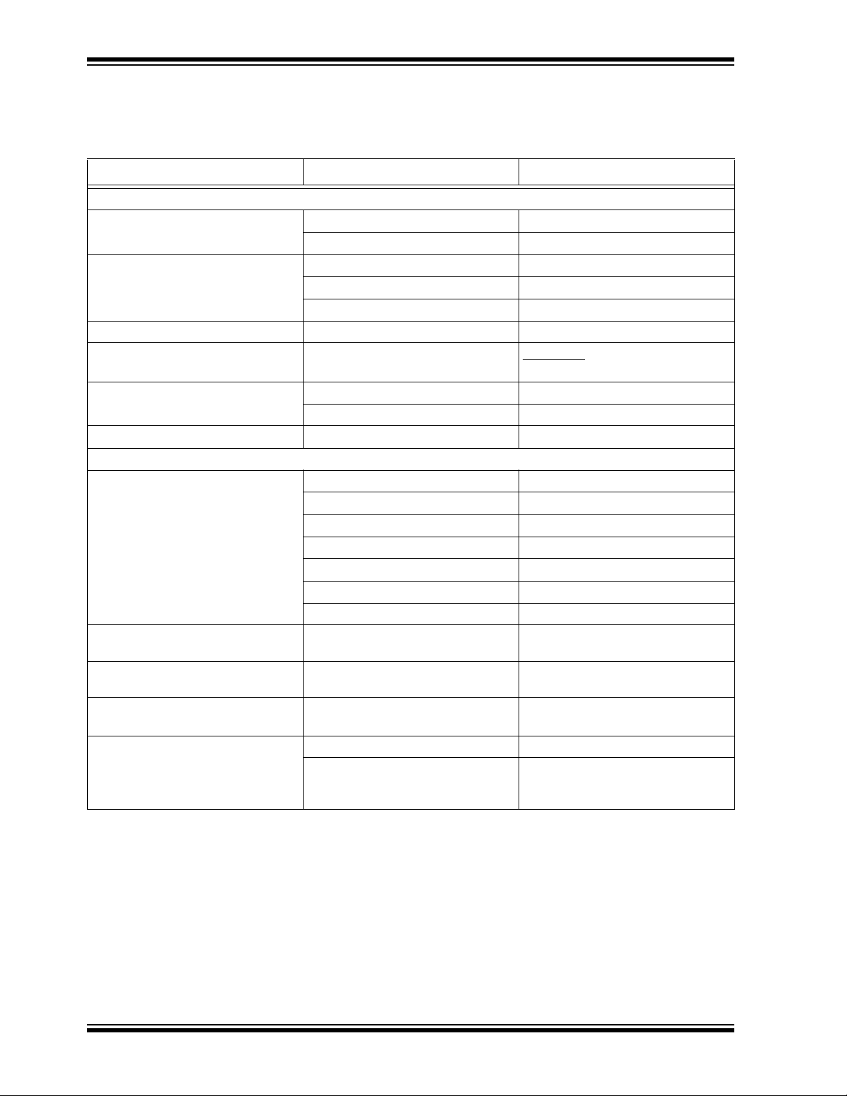
CONVENTIONS USED IN THIS GUIDE
This manual uses the following documentation conventions:
DOCUMENTATION CONVENTIONS
Description Represents Examples
Arial font:
Italic characters Referenced books MPLAB
Emphasized text ...is the only compiler...
Initial caps A window the Output window
A dialog the Settings dialog
A menu selection select Enable Programmer
Quotes A field name in a window or dialog “Save project before build”
Underlined, italic text with right
A menu path File>Save
angle bracket
Bold characters A dialog button Click OK
A tab Click the Power tab
Text in angle brackets < > A key on the keyboard Press <Enter>, <F1>
Courier New font:
Plain Courier New
Sample source code
Filenames
File paths
Keywords
Command-line options
Bit values
Constants (in source code)
Italic Courier New A variable argument
#define START
autoexec.bat
C:\mcc18\h
_asm, _endasm, static
-Opa+, -Opa-
0, 1
0xFF, ‘A’
file.o, where
valid filename
Square brackets [ ] Optional arguments
Curly brackets and pipe
character: { | }
Choice of mutually exclusive
arguments; an OR selection
Ellipses... Replaces repeated text
Represents code supplied by user
mcc18 [options] file
[options]
errorlevel {0|1}
var_name [, var_name...]
void main (void)
{ ...
}
®
IDE User’s Guide
file can be any
DS70662A-page 6 © 2011 Microchip Technology Inc.
Page 7

RECOMMENDED READING
This user’s guide describes how to use the Audio Development Board. The following
Microchip documents are available and recommended as supplemental reference
resources.
MPLAB® C Compiler for PIC24 MCUs and dsPIC® DSCs User’s Guide
(DS51284)
This document helps you use Microchip’s 16-bit C compilers to develop your application.The compilers are the MPLAB C Compiler for dsPIC DSCs and PIC24 MCUs, the
MPLAB C Compiler for dsPIC DSCs (subset of the first), and the MPLAB C Compiler
for PIC24 MCUs (subset of the first). These compilers are GNU-based language tools,
based on source code from the Free Software Foundation (FSF). For more information
about FSF, see www.fsf.org.
MPLAB® Assembler, Linker and Utilities for PIC24 MCUs and dsPIC®
DSCs User’s Guide (DS51317)
This document helps you use Microchip Technology’s 16-bit language tools based on
GNU technology. The language tools discussed are the MPLAB Assembler for dsPIC
DSCs and PIC24 MCUs, MPLAB Object Linker for dsPIC DSCs and PIC24 MCUs,
MPLAB Archiver/Librarian for dsPIC DSCs and PIC24 MCUs and other 16-bit device
utilities.
Preface
MPLAB® C Compiler for PIC32 User’s Guide (DS51686)
This document, formerly the “MPLAB C32 C Compiler for PIC32 User’s Guide”, details
the use of Microchip’s MPLAB C Compiler for PIC32 to develop an application.
MPLAB® IDE User’s Guide (DS51519)
Consult this document for more information pertaining to the installation and
implementation of the MPLAB IDE software, as well as the MPLAB Editor and MPLAB
SIM Simulator software that are included with it.
Universal Serial Bus Specification and Associated Documents
The Universal Serial Bus is defined by the USB 2.0 specification and its associated
supplements and class-specific documents. These documents are available from the
USB Implementers Forum. See their website at: http://www.usb.org
ADDITIONAL INFORMATION
iPod is a registered trademark of Apple, Inc., registered in the U.S. and other countries.
© 2011 Microchip Technology Inc. DS70662A-page 7
Page 8

Audio Development Board User’s Guide
THE MICROCHIP WEB SITE
Microchip provides online support via our web site at: http://www.microchip.com. This
web site makes files and information easily available to customers. Accessible by most
Internet browsers, the web site contains the following information:
• Product Support – Data sheets and errata, application notes and sample
programs, design resources, user’s guides and hardware support documents,
latest software releases and archived software
• General Technical Support – Frequently Asked Questions (FAQs), technical
support requests, online discussion groups, Microchip consultant program
member listings
• Business of Microchip – Product selector and ordering guides, latest Microchip
press releases, listings of seminars and events; and listings of Microchip sales
offices, distributors and factory representatives
DEVELOPMENT SYSTEMS CUSTOMER CHANGE NOTIFICATION SERVICE
Microchip’s customer notification service helps keep customers current on Microchip
products. Subscribers will receive e-mail notification whenever there are changes,
updates, revisions or errata related to a specified product family or development tool of
interest.
To register, access the Microchip web site at http://www.microchip.com, click
Customer Change Notification and follow the registration instructions.
The Development Systems product group categories are:
• Compilers – The latest information on Microchip C compilers and other language
tools. These include the MPLAB
assemblers; MPLINK™ and MPLAB 16-bit object linkers; and MPLIB™ and
MPLAB 16-bit object librarians.
• Emulators – The latest information on the Microchip MPLAB
In-Circuit Emulator.
• In-Circuit Debuggers – The latest information on the Microchip in-circuit
debugger, MPLAB ICD 3.
• MPLAB IDE – The latest information on Microchip MPLAB IDE, the Windows
Integrated Development Environment for development systems tools. This list is
focused on the MPLAB IDE, MPLAB SIM simulator, MPLAB IDE Project Manager
and general editing and debugging features.
• Programmers – The latest information on Microchip programmers. These include
the MPLAB PM3 device programmer and the PICkit™ 3 development
programmers.
®
C compiler; MPASM™ and MPLAB 16-bit
®
REAL ICE™
®
CUSTOMER SUPPORT
Users of Microchip products can receive assistance through several channels:
• Distributor or Representative
• Local Sales Office
• Field Application Engineer (FAE)
• Technical Support
Customers should contact their distributor, representative or field application engineer
(FAE) for support. Local sales offices are also available to help customers. A listing of
sales offices and locations is included in the back of this document.
Technical support is available through our web site at: http://microchip.com/support
DS70662A-page 8 © 2011 Microchip Technology Inc.
Page 9

DOCUMENT REVISION HISTORY
Revision A (May 2011)
This is the initial release of the Audio Development Board User’s Guide.
Preface
© 2011 Microchip Technology Inc. DS70662A-page 9
Page 10

Audio Development Board User’s Guide
NOTES:
DS70662A-page 10 © 2011 Microchip Technology Inc.
Page 11

Thank you for purchasing an Audio Development Board from Microchip Technology
1
2
3
4
5
6
7
8
8
9
10
11
12
8
8
13
14
14
14
Inc. The Audio Development Board showcases a 16/32-bit audio development platform
with a true 24-bit audio codec. In addition, the board also showcases the performance
of PIC32 MCU/dsPIC33E DSC for complex audio algorithms.
1.1 OVERVIEW
The features of the Audio Development Board are:
• High-performance MCU
• Wolfson WM8960 audio codec with up to 48 kHz sampling rate and up to 24-bit
• Headphone out, Line-in jacks, and an on-board MIC
• TFT color display with 220x176 resolution
• PICtail™ Plus Connector
• General purpose user switches and LEDs
Figure 1-1 shows the Audio Development Board, which is annotated to show the main
components. Each component is described in detail in Ta bl e 1 -1 .
AUDIO DEVELOPMENT BOARD
USER’S GUIDE
Chapter 1. Introduction
resolution
FIGURE 1-1: AUDIO DEVELOPMENT BOARD
© 2011 Microchip Technology Inc. DS70662A-page 11
Page 12

Audio Development Board User’s Guide
TABLE 1-1: AUDIO DEVELOPMENT BOARD COMPONENT DESCRIPTIONS
Item
Number
1 J1 9V DC power connector.
2 U2 Microcontroller.
3 U1 Wolfson WM8960 audio codec.
4 J2 PICtail Plus Connector for iPod
5 LCD1 2-inch (220x176) TFT display.
6 J7 USB interface connector.
7 J10 RS-232 serial UART connector.
8 S1, S2, S3, S4 General purpose user application switches.
9 MIC1 Condenser microphone.
10 HP OUT 3.5 mm stereo headphone socket.
11 Line IN Line input socket.
12 J3 RJ-45 debugger connector.
13 RESET1 Device Reset switch.
14 D3, D4, D5 General purpose user LEDs.
Refer to Chapter 2. “Hardware” for detailed hardware descriptions
Component
Label
Description
®
PICtail™ Plus Board.
DS70662A-page 12 © 2011 Microchip Technology Inc.
Page 13

This chapter provides a functional overview of the hardware used in the Audio
Development Board and identifies the major hardware components.
Topics covered include:
• Power Supply
• Microcontroller
• Audio Codec, Microphone and Audio Connections
• PICtail™ Plus Connector
• TFT Display
• USB Connectivity
• UART Connectivity
• User LEDs and Switches
2.1 POWER SUPPLY
Power can be supplied to the Audio Development Board through the DC connector
(J1). By connecting a 9V power supply to the DC connector, the Audio Development
Board and the expansion connector will receive the proper voltages.
AUDIO DEVELOPMENT BOARD
USER’S GUIDE
Chapter 2. Hardware
Care should be exercised while working with headphones or speakers. Exposure to
high volumes can result in hearing damage. The use of headphones or speakers with
built-in volume control is recommended.
2.2 MICROCONTROLLER
The microcontroller (U2) on-board the Audio Development Board is a 16/32-bit,
high-performance microcontroller (MCU). The clock requirement is met via the 8 MHz
external crystal oscillator (Y2). The device can be placed in Reset by activating the
RESET1 switch.
A debugger or programmer such as MPLAB
3 can be used via the RJ-45 (J3) connector. The debugging interface is implemented
via the ICSP™ protocol and the external debugger is connected to the ICSP socket
(J3).
CAUTION
®
REAL ICE™ In-Circuit Emulator or ICD
© 2011 Microchip Technology Inc. DS70662A-page 13
Page 14

Audio Development Board User’s Guide
2.3 AUDIO CODEC, MICROPHONE AND AUDIO CONNECTIONS
The audio codec (U1) is a Wolfson WM8960. The codec is of hi-fi quality with up to
24-bit resolution. The sampling rates supported are between 8 kHz to 48 kHz and
includes an on-chip flexible PLL. The codec has a built-in headphone driver and a stereo Class D speaker driver. In addition, it has low-power consumption and offers a
small foot print. On 32-bit microcontroller, the codec data interface is handled through
the SPI module in Framed SPI mode. On 16-bit microcontroller, the codec data interface is handled through the DCI module. The control registers of the codec are configured over the I
oscillator.
The condenser microphone (MIC1) is available on the board for capturing audio. The
microphone bias voltage is provided directly by the codec and is connected via Line
Input 1 of the codec. The microphone bias voltage level and sensitivity are controlled
via the codec registers. The microphone signal is presented as a mono signal to the
application.
The line-in jack (Line IN) is available to interface to audio signal sources (such as CD
players and musical instruments) that use line level ouputs.The line input signal is a
stereo signal and is connected to Left Input 2 and Right Input 2 of the codec.
Note: The maximum line input signal level should not exceed 0.5Vrms on
2
C interface. The codec external clock is provided by a 12 MHz crystal
differential and 1Vrms on single-ended input.
The Headphone jack (HP OUT) is a 3.5 mm stereo socket that connects to the codec
headphone amplifier, with the headphone signal output as a true stereo signal. Any
commercially available headphone can be connected to the headphone jack. The
headphone volume and the headphone input signal are configurable via the codec
registers. The codec outputs a maximum of 20 mW into a 32 Ohm headphone.
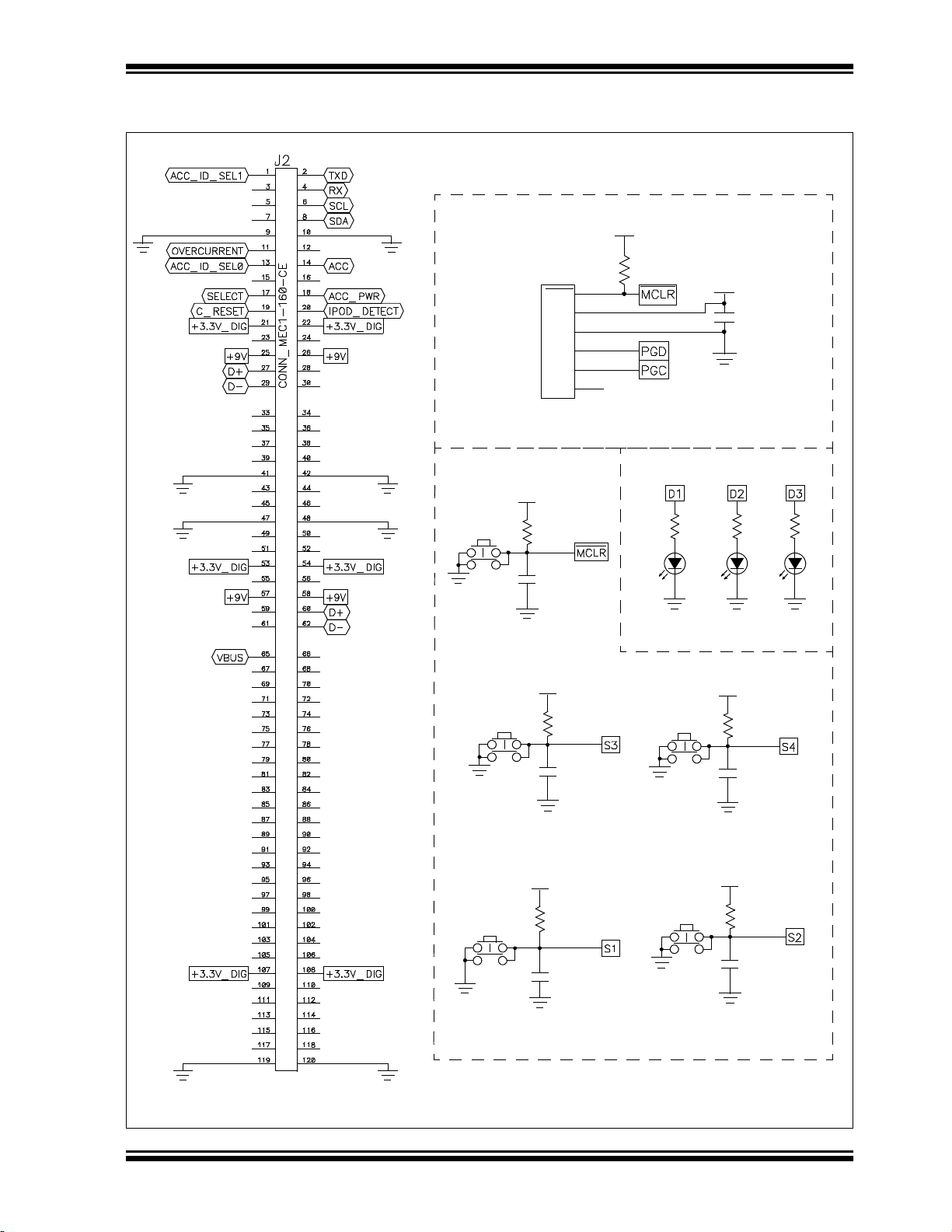
2.4 PICtail™ PLUS CONNECTOR
The expansion connector (J2) on the Audio Development Board can be used to enable
Made for iPod (MFi) features for an iPod
connector is not compatible with any other PICtail Plus Daughter boards.
2.5 TFT DISPLAY
The Audio Development Board has a 2 inch TFT display (LCD1) with a resolution of
220x176 for a maximum of 262K colors. The display is controlled by a chip-on-glass
OTM2201A display controller. The display controller requires 8-bit parallel interface.
The Parallel Master Port (PMP) on the MCU is used to interface to the display
controller.
2.6 USB CONNECTIVITY
The Audio Development Board features USB Host support (J7). This connector allows
applications to interface to USB devices such as a USB Thumb Drive, USB mouse, and
so on. The USB module on the MCU provides the required USB Host functionality. A
5V switch controlled by the MCU controls the power supply to the attached USB device.
®
PICtail Plus board. The PICtail Plus
DS70662A-page 14 © 2011 Microchip Technology Inc.
Page 15

2.7 UART CONNECTIVITY
The RS-232 Serial port (J10) provides a general purpose serial communication port for
application use. The MAX3232CUE (U4) RS-232 transceiver provides the required
translation level and connects to a UART on the MCU (U2).
2.8 USER LEDS AND SWITCHES
The general purpose LEDs, D3, D4, and D5, are available for application use. The
LEDs are connected to the MCU (U2) output ports. Setting the port high will activate
the LED.
The general purpose push button switches S1, S2, S3, and S4, are available for
application use. All four switches are connected to the MCU input ports. Activating a
switch will cause the port line to pull low.
Note: Switches S2 and S3 are marked on the board as controlling volume;
however, these switches do not control the volume of the codec (U1) DAC
directly. The codec DAC volume is controlled by the on-board device (U2).
Hardware
© 2011 Microchip Technology Inc. DS70662A-page 15
Page 16

Audio Development Board User’s Guide
NOTES:
DS70662A-page 16 © 2011 Microchip Technology Inc.
Page 17

AUDIO DEVELOPMENT BOARD
+3.3V_DIG
+3.3V_DIG
R19 6.8ohms
R18
6.8ohms
0R
R17
R20 6.8ohms
Appendix A. Schematics and Board Layout
A.1 AUDIO DEVELOPMENT BOARD SCHEMATICS
FIGURE A-1: DISPLAY CIRCUIT
USER’S GUIDE
© 2011 Microchip Technology Inc. DS70662A-page 17
Page 18

DS70662A-page 18 © 2011 Microchip Technology Inc.
C27
10uF
C23
10uF
C17
4.7uF
+3.3V_DIG
R4
5.6K
C13
1uF
C20
4.7uF
+3.3V_ANA
R8
4.7K
C15
0.1uF
R6
5.6K
C11
1uF
100uF
C21
220pF
C12
5.6K
R5
0.1uF
C19
+3.3V_ANA
100uF
C22
+3.3V_DIG
R9
4.7K
5.6K
R3
C14
220pF
J5
C18
4.7uF
+3.3V_ANA
C16
0.1uF
+3.3V_DIG
R7
2.2K
J6
U1
WM8960_QFN32
FIGURE A-2: AUDIO CIRCUIT
Audio Development Board User’s Guide
Page 19

© 2011 Microchip Technology Inc. DS70662A-page 19
+3.3V_DIG
1uF
C42
C39
1uF
+3.3V_DIG
1uF
C37
C41
1uF
+3.3V_DIG
0 ohmsR21
+3.3V_DIG
1uF
C43
C28
0.1uF
+3.3V_DIG
C30
100uF
+3.3V_DIG
+3.3V_DIG
0 ohmsR22
Y2
8Mhz
R24 0 ohms
+3.3V_DIG
C45
18pF
C44
18pF
R23 0 ohms
USB-Type A
+3.3V_DIG
FIGURE A-3: MICROCONTROLLER AND USB CIRCUITS
Schematics and Board Layout
Page 20

DS70662A-page 20 © 2011 Microchip Technology Inc.
C7
1UF
1uF
C1
C8
10uF
+3.3V_DIG +3.3V_DIG +3.3V_DIG +3.3V_DIG
0.1uF
C24
0.1uF
C25
10uF
C29
C5
0.1uF
0.1uF
C35
C46
0.1uF
C47
0.1uF
C48
0.1uF
+9V
+9V
+3.3V_DIG
+3.3V_ANA
C9
0.1uF
0R
R25
+3.3V_DIG
R1
470R
+3.3V_DIG
+3.3V_DIG
+3.3V_DIG + 3.3V_DIG
C2
0.1uF
C3
10uF
C4
1uF
0.1uF
C26
C36
0.1uF
C38
0.1uF
C6
10uF
Power
D2
+3.3V_DIG
LM1117MPX-3.3
VR2
LM1117MP-5.0
VR1
FIGURE A-4: POWER CIRCUITS
Audio Development Board User’s Guide
Page 21
Schematics and Board Layout
DNP
R2
4
3
2
1
S3
D4
4
3
2
1
RESET1
D5
+3.3V_DIG
0.1uF
C10
4
3
2
1
S2
4
3
2
1
S4
R11
470R
R12
470R
Expansion Connector
+3.3V_DIG
0.1uF
C32
0.1uF
C40
10K
R14
+3.3V_DIG
+3.3V_DIG
10K
R27
0.1uF
C31
0.1uF
C33
4
3
2
1
S1
+3.3V_DIG
+3.3V_DIG
D3
0.1uF
C34
+3.3V_DIG
10K
R13
10K
R15
R10
470R
R16
10K
4
PGD
1
MCLR
2
VDD
3
VSS
5
PGC
6
N.C.
RJ11_6PIN
J3
ICSP
LEDs
General Purpose Switches
FIGURE A-5: COMMUNICATION CIRCUITS
(EXPANSION CONNECTOR, ICSP, SWITCHES, AND LEDs)
© 2011 Microchip Technology Inc. DS70662A-page 21
Page 22

DS70662A-page 22 © 2011 Microchip Technology Inc.
A.2 AUDIO DEVELOPMENT BOARD LAYOUT
FIGURE A-6: BOARD LAYOUT (TOP)
Audio Development Board User’s Guide
Page 23

NOTES:
© 2011 Microchip Technology Inc. DS70662A-page 23
Page 24

Worldwide Sales and Service
AMERICAS
Corporate Office
2355 West Chandler Blvd.
Chandler, AZ 85224-6199
Tel: 480-792-7200
Fax: 480-792-7277
Technical Support:
http://www.microchip.com/
support
Web Address:
www.microchip.com
Atlanta
Duluth, GA
Tel: 678-957-9614
Fax: 678-957-1455
Boston
Westborough, MA
Tel: 774-760-0087
Fax: 774-760-0088
Chicago
Itasca, IL
Tel: 630-285-0071
Fax: 630-285-0075
Cleveland
Independence, OH
Tel: 216-447-0464
Fax: 216-447-0643
Dallas
Addison, TX
Tel: 972-818-7423
Fax: 972-818-2924
Detroit
Farmington Hills, MI
Tel: 248-538-2250
Fax: 248-538-2260
Indianapolis
Noblesville, IN
Tel: 317-773-8323
Fax: 317-773-5453
Los Angeles
Mission Viejo, CA
Tel: 949-462-9523
Fax: 949-462-9608
Santa Clara
Santa Clara, CA
Tel: 408-961-6444
Fax: 408-961-6445
Toronto
Mississauga, Ontario,
Canada
Tel: 905-673-0699
Fax: 905-673-6509
ASIA/PACIFIC
Asia Pacific Office
Suites 3707-14, 37th Floor
Tower 6, The Gateway
Harbour City, Kowloon
Hong Kong
Tel: 852-2401-1200
Fax: 852-2401-3431
Australia - Sydney
Tel: 61-2-9868-6733
Fax: 61-2-9868-6755
China - Beijing
Tel: 86-10-8569-7000
Fax: 86-10-8528-2104
China - Chengdu
Tel: 86-28-8665-5511
Fax: 86-28-8665-7889
China - Chongqing
Tel: 86-23-8980-9588
Fax: 86-23-8980-9500
China - Hangzhou
Tel: 86-571-2819-3180
Fax: 86-571-2819-3189
China - Hong Kong SAR
Tel: 852-2401-1200
Fax: 852-2401-3431
China - Nanjing
Tel: 86-25-8473-2460
Fax: 86-25-8473-2470
China - Qingdao
Tel: 86-532-8502-7355
Fax: 86-532-8502-7205
China - Shanghai
Tel: 86-21-5407-5533
Fax: 86-21-5407-5066
China - Shenyang
Tel: 86-24-2334-2829
Fax: 86-24-2334-2393
China - Shenzhen
Tel: 86-755-8203-2660
Fax: 86-755-8203-1760
China - Wuhan
Tel: 86-27-5980-5300
Fax: 86-27-5980-5118
China - Xian
Tel: 86-29-8833-7252
Fax: 86-29-8833-7256
China - Xiamen
Tel: 86-592-2388138
Fax: 86-592-2388130
China - Zhuhai
Tel: 86-756-3210040
Fax: 86-756-3210049
ASIA/PACIFIC
India - Bangalore
Tel: 91-80-3090-4444
Fax: 91-80-3090-4123
India - New Delhi
Tel: 91-11-4160-8631
Fax: 91-11-4160-8632
India - Pune
Tel: 91-20-2566-1512
Fax: 91-20-2566-1513
Japan - Yokohama
Tel: 81-45-471- 6166
Fax: 81-45-471-6122
Korea - Daegu
Tel: 82-53-744-4301
Fax: 82-53-744-4302
Korea - Seoul
Tel: 82-2-554-7200
Fax: 82-2-558-5932 or
82-2-558-5934
Malaysia - Kuala Lumpur
Tel: 60-3-6201-9857
Fax: 60-3-6201-9859
Malaysia - Penang
Tel: 60-4-227-8870
Fax: 60-4-227-4068
Philippines - Manila
Tel: 63-2-634-9065
Fax: 63-2-634-9069
Singapore
Tel: 65-6334-8870
Fax: 65-6334-8850
Taiwan - Hsin Chu
Tel: 886-3-6578-300
Fax: 886-3-6578-370
Taiwan - Kaohsiung
Tel: 886-7-213-7830
Fax: 886-7-330-9305
Taiwan - Taipei
Tel: 886-2-2500-6610
Fax: 886-2-2508-0102
Thailand - Bangkok
Tel: 66-2-694-1351
Fax: 66-2-694-1350
EUROPE
Austria - Wels
Tel: 43-7242-2244-39
Fax: 43-7242-2244-393
Denmark - Copenhagen
Tel: 45-4450-2828
Fax: 45-4485-2829
France - Paris
Tel: 33-1-69-53-63-20
Fax: 33-1-69-30-90-79
Germany - Munich
Tel: 49-89-627-144-0
Fax: 49-89-627-144-44
Italy - Milan
Tel: 39-0331-742611
Fax: 39-0331-466781
Netherlands - Drunen
Tel: 31-416-690399
Fax: 31-416-690340
Spain - Madrid
Tel: 34-91-708-08-90
Fax: 34-91-708-08-91
UK - Wokingham
Tel: 44-118-921-5869
Fax: 44-118-921-5820
05/02/11
DS70662A-page 24 © 2011 Microchip Technology Inc.
 Loading...