

Page 1
mTouch™ AR1100
Analog Resistive USB and RS-232
Touch Screen Controller Board
User’s Guide
2011 Microchip Technology Inc. DS41604A
Page 2
Note the following details of the code protection feature on Microchip devices:
• Microchip products meet the specification contained in their particular Microchip Data Sheet.
• Microchip believes that its family of products is one of the most secure families of its kind on the market today, when used in the
intended manner and under normal conditions.
• There are dishonest and possibly illegal methods used to breach the code protection feature. All of these methods, to our
knowledge, require using the Microchip products in a manner outside the operating specifications contained in Microchip’s Data
Sheets. Most likely, the person doing so is engaged in theft of intellectual property.
• Microchip is willing to work with the customer who is concerned about the integrity of their code.
• Neither Microchip nor any other semiconductor manufacturer can guarantee the security of their code. Code protection does not
mean that we are guaranteeing the product as “unbreakable.”
Code protection is constantly evolving. We at Microchip are committed to continuously improving the code protection features of our
products. Attempts to break Microchip’s code protection feature may be a violation of the Digital Millennium Copyright Act. If such acts
allow unauthorized access to your software or other copyrighted work, you may have a right to sue for relief under that Act.
Information contained in this publication regarding device
applications and t he lik e is provided only for your convenience
and may be su perseded by upda t es . It is y our responsibility to
ensure that your application meets with your specifications.
MICROCHIP MAKES NO REPRESENTATIONS OR
WARRANTIES OF ANY KIND WHETHER EXPRESS OR
IMPLIED, WRITTEN OR ORAL, STATUTORY OR
OTHERWISE, RELATED TO THE INFORMATION,
INCLUDING BUT NOT LIMITED TO ITS CONDITION,
QUALITY, PERFORMANCE, MERCHANTABILITY OR
FITNESS FOR PURPOSE. Microchip disclaims all liability
arising from this information and its use. Use of Microchip
devices in life supp ort and/or safety ap plications is entir ely at
the buyer’s risk, and the buyer agrees to defend, indemnify and
hold harmless M icrochip from any and all dama ges, claims,
suits, or expenses re sulting from such use. No licens es are
conveyed, implicitly or otherwise, under any Microchip
intellectual property rights.
Trademarks
The Microchip name and logo, the Microchip logo, dsPIC,
K
EELOQ, KEELOQ logo, MPLAB, PIC, PICmicro, PICSTART,
32
PIC
logo, rfPIC and UNI/O are registered trademarks of
Microchip Technology Incorporated in the U.S.A. and other
countries.
FilterLab, Hampshire, HI-TECH C, Linear Active Thermistor,
MXDEV, MXLAB, SEEVAL and The Embedded Control
Solutions Company are registered trademarks of Microchip
Technology Incorporated in the U.S.A.
Analog-for-the-Digital Age, Application Maestro, chipKIT,
chipKIT logo, CodeGuard, dsPICDEM, dsPICDEM.net,
dsPICworks, dsSPEAK, ECAN, ECONOMONITOR,
FanSense, HI-TIDE, In-Circuit Serial Programming, ICSP,
Mindi, MiWi, MPASM, MPLAB Certified logo, MPLIB,
MPLINK, mTouch, Omniscient Code Generation, PICC,
PICC-18, PICDEM, PICDEM.net, PICkit, PICtail, REAL ICE,
rfLAB, Select Mode, Total Endurance, TSHARC,
UniWinDriver, WiperLock and ZENA are trademarks of
Microchip Technology Incorporated in the U.S.A. and other
countries.
SQTP is a service mark of Microchip Technology Incorporated
in the U.S.A.
All other trademarks mentioned herein are property of their
respective companies.
© 2011, Microchip Technology Incorporated, Printed in the
U.S.A., All Rights Reserved.
Printed on recycled paper.
ISBN: 978-1-61341-491-0
Microchip received ISO/TS-16949:2009 certification for its worldwide
headquarters, design and wafer fabrication facilities in Chandler and
Tempe, Arizona; Gresham, Oregon and design centers in California
and India. The Company’s quality system processes and procedures
are for its PIC
devices, Serial EEPROMs, microperipherals, nonvolatile memory and
analog products. In addition, Microchip’s quality system for the design
and manufacture of development systems is ISO 9001:2000 certified.
®
MCUs and dsPIC® DSCs, KEELOQ
®
code hopping
DS41604A-page 2 2011 Microchip Technology Inc.
Page 3
mTouch™ AR1100 User’s Guide
Table of Contents
Preface ...........................................................................................................................5
Introduction............................................................................................................5
Document Layout .................................................................................................. 6
Recommended Reading.............................................................. .. ........................6
The Microchip Web Site........................................................................................ 6
Customer Support.................... .................................... .................. .......................7
Document Revision History................................................................................... 7
Chapter 1. Product Overview
1.1 Introduction .....................................................................................................9
1.2 Product Description ........................................................................................9
Chapter 2. Connections
2.1 Mounting .......................................................................................................13
2.2 Power ............. .. ............................. .............................................................. 13
2.3 Communic a ti o n ............ ............... ................................................................. 14
2.4 Sensor ........ ............................................................................................... ... 1 6
Chapter 3. Operation
3.1 Configur ation .............. ............................................................................... .. . 19
3.2 Communic a ti o n ............ ............... ................................................................. 19
3.3 Data Forma t ............. ....................................................... ............................. 1 9
3.4 LED Indica t o r ......... ........................................ .. .. ........................................... 2 1
Chapter 4. Software Device Drivers
Chapter 5. Accessories
5.1 Communic a ti o n Ca b le s ................................................................................ 25
5.2 Touch Scre e n C a bl e s ..................................................................... .............. 25
Chapter 6. Support
Chapter 7. Touch Screen Sel ection
Index .............................................................................................................................31
Worldwide Sales and Service ....................................................................................32
2011 Microchip Technology Inc. DS41604A-page 3
Page 4

mTouch™ AR1100 User’s Guide
NOTES:
DS41604A-page 4 2011 Microchip Technology Inc.
Page 5
mTouch™ AR1100 User’s Guide
Preface
NOTICE TO CUSTOMERS
All documentation becomes dated, and this manual is no exception. Microchip tools and
documentation are constantly evolving to meet customer needs, so some actual dialogs
and/or tool descriptions may differ from those in this document. Please refer to our web site
(www.microchip.com) to obtain the latest documentation available.
Documents are identified with a “DS” number. This number is located on the bottom of each
page, in front of the p age number. The numbering convention for the DS number is
“DSXXXXXA”, where “XXXXX” is the document number and “A” is the revision level of the
document.
For the most up-to-date information on development tools, see the MPLAB
Select the Help menu, and then Topics to open a list of available online help files.
INTRODUCTION
This chapter conta ins the gener al infor mati on that will b e use ful to kno w befor e usin g
the mTouc h™ AR1100 Ana log Resistive USB and RS-232 Tou ch Screen Controller
Board. Items discussed in this chapter include:
• Document Layout
• Recommended Reading
• The Microchip Web Site
• Customer Support
• Document Revision History
®
IDE on-line help.
2011 Microchip Technology Inc. DS41604A-page 5
Page 6

mTouch™ AR1100 User’s Guide
DOCUMENT LAYOUT
This document describes how to use the mT ouch™ AR1 100 Analog Resistive USB and
RS-232 Touch Screen Controller Board. The manual layout is as follows:
• Chapter 1. “Product Overview”
• Chapter 2. “Connect ion s”
• Chapter 3. “Operation”
• Chapter 4. “Software Device Drivers”
• Chapter 5. “Access ories ”
• Chapter 6. “Support”
• Chapter 7. “Touch Screen Selection”
RECOMMENDED READING
This user’s gui de descr ibes how to use the m Touch™ AR110 0 Analo g Resisti ve USB
and RS-232 Touch Screen Controller Board. Other useful documents are listed below.
The following Microc hi p d ocu men ts are av ai la ble an d r ec omm end ed as su ppl em ental
reference resources.
Readme for mTouch™ AR1100 Analog Resistive USB and RS-232 Touch Screen
Controller Board
For the latest information on using mTouch™ AR1100 Analog Resistive USB and
RS-232 T ouch Screen Controller Board, read the “Readme.txt” file in the main i nst al lation directory. The Readme file contains updated information and known issues that
may not be included in this user’s guide.
Readme Files
For the latest information on using other tools, read the tool-specific Readme files in
the Readme subdirectory of the MPLAB IDE installation directory. The Readme files
contain update information and known issues that may not be included in this user’s
guide.
THE MICROCHI P WEB SITE
Microchip provides o nline support through our web site at www.micr ochip.com.This
web site is used as a means to make files and information easily available to
customers. Acces sible by using your favo rite Internet browse r, the web site contains
the following information:
• Product Support – Data sheets and errata, application notes and sample
programs, design resources, user’s guides and hardware support documents,
latest software releases and archived software
• General Technical Support – Frequently Asked Questions (FAQs), technical
support requests, online discussion groups, Microchip consultant program
member listin g
• Business of Microchip – Product selector and ordering guides, latest Microchi p
press releases, list ing of seminars and events, listings of Microchip sal es offices,
distributors and factory representatives
DS41604A-page 6 2011 Microchip Technology Inc.
Page 7

CUSTOMER SUPPORT
Users of Microchip products can receive assistance through several channels:
• Distributor or Representative
• Local Sales Office
• Field Application Engineer (FAE)
• Technical Support
Customers should contact their distributor, representative or field application engineer
(FAE) for support. Local sales offices are also available to help customers. A listing of
sales offices and locations is included in the back of this document.
Technical support is available through the web site at: http://support.microchip.com
DOCUMENT REVISION HISTORY
Revision A (August 2011)
Initial release of this document.
Preface
2011 Microchip Technology Inc. DS41604 A-page 7
Page 8

mTouch™ AR1100 User’s Guide
NOTES:
DS41604A-page 8 2011 Microchip Technology Inc.
Page 9

Chapter 1. Product Overview
1.1 INTRODUCTION
The Microchip mTouchTM AR1100 Analog Resistive USB and RS-232 Touch Screen
Controller Board represents a feature-rich, fully-integrated universal touch screen
controller solution. The AR1100 Touch Screen Controller Board automatically selects
between USB and RS-232 communication protocols, as well as supports 4, 5 or 8-wire
analog resistive touch screens from any of a variety of touch screen manufacturers.
The AR1100 Touch Screen Controller Board dynamically adapts to the various touch
screen electrical characteristics such as sensitivity, contact resistance, and
capacitance to provide optimal performance with minimal design time.
Building on the AR1000 series, the new AR1100 T ouch Screen Controller Board offers
customers an easy to integrate solution for low-cost, high-performing resistive touch
with the advantages of USB plug and play, support for USB mouse or digitizer,
advanced touch response and accuracy, field-flash updatability, and free drivers for
most operating systems to enable low-risk designs for a wide variety of touch sensing
requirements.
The AR1100 Touch Screen Controller Board supports large displays like industrial controls, self-service kiosks, and POS terminals, as well as smaller tablet displays, handheld consumer devices, and medical devices.
Resistive touch provides the advantages of easy integration, low total system cost and
acceptance of finger, glove or stylus input, and USB communication is the industry
standard for attaching peripherals to a computer. The AR1100 Touch Screen Controller
Board is an easy-to-integrate touch screen controller that meets all of these needs in a
single-chip solution or production ready-board product. The device comes with free
drivers for most major operating systems, making it easy for designers to quickly create
low-risk touch interface solutions.
mTouch™ AR1100 User’s Guide
1.2 PRODUCT DESCRIPTION
The mTouch™ AR1100 Touch Screen Controller Board auto-detects communication
(RS-232 or USB) and uses a jumper to select between 5-wire and 4/8-wire analog
resistive touch screens. The AR1100 Touch Screen Controller Board is ready to go out
of the box with little or no configuration.
1.2.1 Part Number
AR1100BRD
1.2.2 AR1100 Core Feat ures:
•RoHS Compliant
• Automatically detects communication type
- RS-232 (9600 BAUD) and USB (2.0 Compliant)
- Full-speed USB device HID compliant at 12 Mb/sec.
- Low-power Suspend mode for USB < 500 uA
- Low-power Sleep mode for RS-232 <10 uA
2011 Microchip Technology Inc. DS41604A-page 9
Page 10
mTouch™ AR1100 User’s Guide
• USB plug and play
- USB mouse (HID-MOUSE) or
- Single-touch Win7 digitizer (HID-DIGITIZER)
• Jumper-selectable sensor support
-5 wire
- 4/8 wire
• Dynamic rise-time and sampling capability
• Resolution:
- 10-bit measurement (1024x1024)
- 12-bit reporting (4096x4096) of processed touch coordinates
- Report rate: 150 rps (typical)
- Touch screen resistance – 2k ohm sheet resistance lead to lead.
- Calibration data stored on local EEPROM
- User EEPROM available – 96 bytes
- Flash/Data EEPROM retention: >40 years
- Industry-leading touch response and accuracy
- ESD protection – both communication and touch screen connections
• Static Protection: 24 kVA
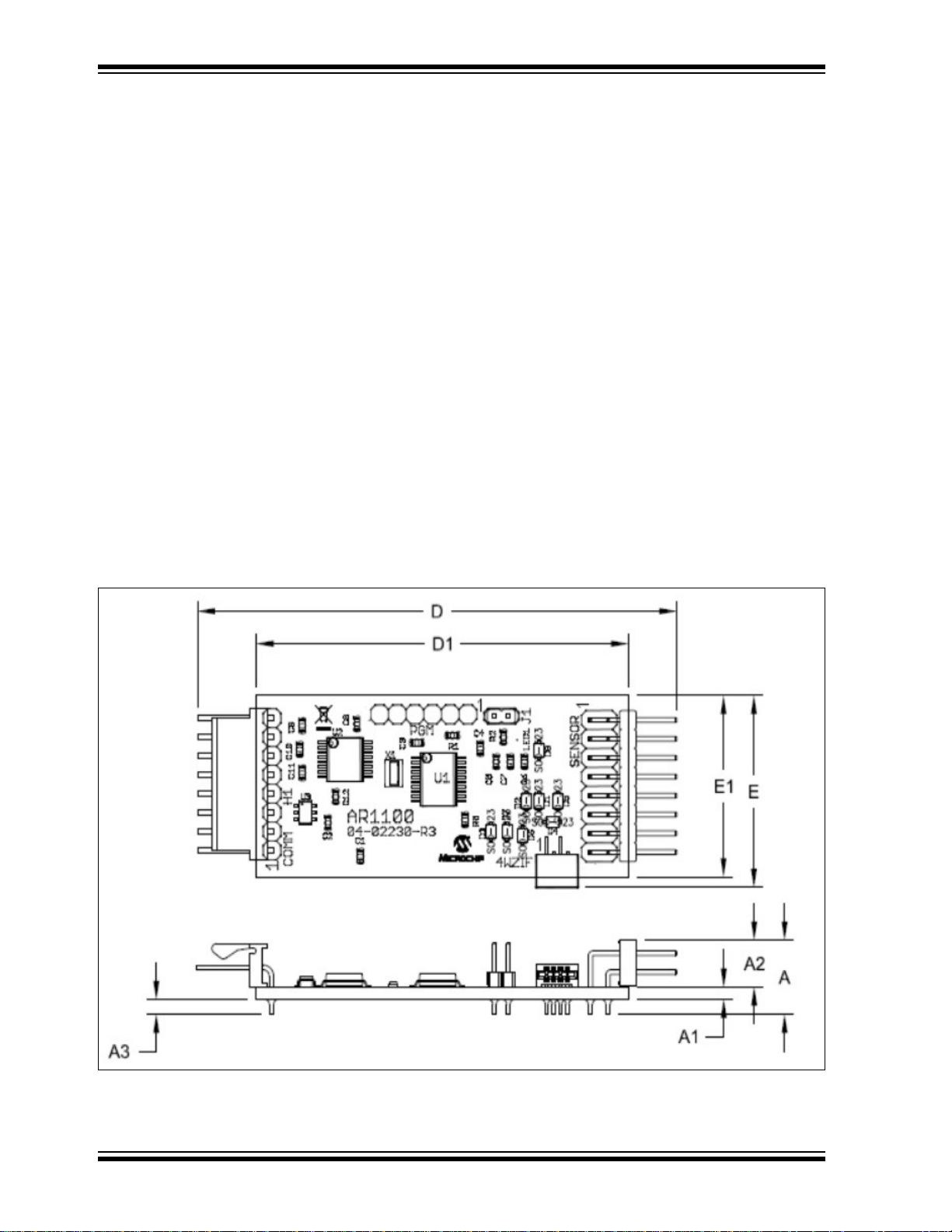
1.2.3 Mechanical
1.2.3.1 DIMENSIONS
FIGURE 1-1: PCB – MECHANICAL DRAWING
DS41604A-page 10 2011 Microchip Technology Inc.
Page 11

Product Overview
TABLE 1-1: PCB – MECHANICAL DIMENSIONS
Units: Millimeters Inches
Dimension Limits: MIN. NOM. MAX. MIN. NOM. MAX.
Overall Length D 67.51 69.02 70.56 2.658 2.718 2.778
Overall Width E 24.28 25.81 27.33 0.956 1.016 1.076
PCB Length D1 52.07 53.59 55.12 2.050 2.110 2.17
PCB Width E1 2.29 24.38 25.91 0.090 0.960 1.02
Overall Height A — — 11.63 — — 0.458
PCB Thickness A1 1.42 15.75 1.73 0.056 0.620 0.068
Component H eight A2 — 6.35 7.87 — 0.250 0.310
Through Hole Lead Trim Length A3 — — 2.03 — — 0.080
Note 1: Passive components omitted from some views for clarity.
2: Dimensions and tolerances per ASME Y14.5M.
BSC: Basic Dimension. Theoretically exact value shown without tolerances.
REF: Refe rence Dimension, usually without tolerance, for infor mation purposes
only.
WARNING
Although Microchip Technology Inc. has taken steps to protect your touch screen controller
from transient voltage, it is important to make all grounding, communication and touch screen
connections to the controller and touch screen. This must be done before powering on your
computer, video monitor or touch screen controller. Failure to follow this procedure may result
in damage to your controller and/or communication port. If you believe that your application
will require additional static protection, it is up to you to determine the appropriate static
protection needed to protect your electronics from transient voltage.
Failure to take the necessary precautions may result in damage to your controller.
Microchip does not warranty the Microchip controller boa rd a gain st t ransie nt stati c di scharge damage
.
2011 Microchip Technology Inc. DS41604A-page 11
Page 12

mTouch™ AR1100 User’s Guide
1.2.4 Electrical
T ABLE 1-2: PCB – ELECTRICAL SPECIFICATIONS
Conditions Min. Typical Max. Units
Supply Voltage 3.3 5.0 V
Supply Current RS-232 (idle) 16 mA
RS-232 (touch) 18
USB (idle) 17
USB (touch) 25
Suspend Current RS232 10 µA
USB 330
Operating temperature Chip -40 125 °C
Board -25 85 °C
Resolution V
Response Time Nor mal 8 ms
Detect Voltage Threshold 1.65 V
Touch Screen Resistance 2000
Touch Capacitance 0 0.5 µF
Note 1: Additional literature is available from Microchip Technology Inc. – definitions,
specifications, and other general touch screen information.
CC: +5V, VDD: Gnd 1024 x 1024 Pixels
Waking 10
DS41604A-page 12 2011 Microchip Technology Inc.
Page 13

mTouch™ AR1100 User’s Guide
Chapter 2. Connections
FIGURE 2-1: CONNECTIONS – OVERVIEW
2.1 MOUNTING
Two static ground mounting holes (0.122" diameter) are provided. T ake special care to
insulate the controller from system and from EMI and RFI generating components of
the display. Use conductive 4-40 stand-offs or ground-lead wires terminated to the
grounded system enclosure or PC board to insure proper static protection and
grounding. STANDOFFS MUST NOT TOUCH ANY PORTION OF THE CIRCUIT.
Position the controller in a location that minimizes bending or creasing of the touch
screen overlay connection tail. Wear to the tail, printed traces, or tail header will
negatively impact touch screen performance.
2.2 POWER
Power to the AR1100 Touch Screen Controller Board is provided by the H1
communication connector as seen in Figure 2-2. In USB Communication mode, power
can be derived from the USB bus. In RS-232 mode – regulated power (3.3V – 5.0V) is
provided from an external source. Check connections before applying power to the
controller as reversing polarity WILL damage the board.
FIGURE 2-2: POWER
2011 Microchip Technology Inc. DS41604A-page 13
Page 14

mTouch™ AR1100 User’s Guide
WARNING
SUPPLYING POWER FROM TWO DIFFERENT POWER SOURCES WILL
PERMANENTLY DESTROY YOUR CONTROLLER, YOUR COMPUTER, OR YOUR
MONITOR.
If the Microchip AR1100 Touch Screen Controller Board is installed into a monitor application where the end user will decide to use USB communication or RS-232 communication, the board must be powered internally. Because the board cannot be supplied
with power from USB and internal 5V, it is recommended that the power (pin 1) contact
be removed from the USB socket to insure that multiple power source connections are
not permitted.
2.3 COMMUNICATION
The AR1100 Touch Screen Controller Board will automatically detect and configure
itself for the active communication protocol – RS-232 or USB HID. The controller will
default to RS-232 communication until USB activity is detected. Once the active
communication mode is determined, the inactive mode is decommissioned to minimize
power consumption. The active communication will remain in effect until power is
removed from the controller.
2.3.1 RS-232
Microchip cable harness p/n: C72-080S1F-09XDXF is a standard 6' long, round
shielded cable terminated by a DB-9 female connector and an 8-position single-row
socket. This cable has a ground termination wire running the length of the cable which
may be utilized to ground the controller board through the DB-9 connector. In any case,
for best performance, a jacketed, shielded cable is recommended.
FIGURE 2-3: RS-232 CONNECTIONS
DS41604A-page 14 2011 Microchip Technology Inc.
Page 15

2.3.2 USB
Microchip cable harness p/n: C72-080S1F-04XAXM-D is a 6' long, jacketed shielded
cable terminated by a Type “A” USB plug and an 8-position, single-row socket. DO NOT
SUPPLY POWER FROM BOTH RS-232 AND USB.
FIGURE 2-4: USB
Connections
WARNING
SUPPLYING POWER FROM TWO DIFFERENT POWER SOURCES COULD
PERMANENTLY DAMAGE YOUR CONTROLLER, YOUR COMPUTER, AND/OR
YOUR MONITOR.
If the Microchip AR1100 Touch Screen Controller Board is installed into a monitor application where the end user will decide to use USB communication or RS-232 communication, the board must be powered internally. Because the board cannot be supplied
with power from USB and internal 5V, it is recommended that the power (pin 1) contact
be removed from the USB socket to insure that multiple power source connections are
not permitted.
2011 Microchip Technology Inc. DS41604A-page 15
Page 16

mTouch™ AR1100 User’s Guide
2.4 SENSOR
The AR1100 Touch Screen Controller Board supports 4, 5 and 8-wire sensors. A 2x8
pin header (“SENSOR”) seen in the mechanical diagram is the connection point for all
3 sensor types. Additionally, a 4-conductor flat flex connector can be used with 4-wire
sensors. An illustration of sensor wiring/construction is given below for reference (see
Figure 2-5).
FIGURE 2-5: SENSOR CONNECTIONS
2.4.1 Connector: “4WZIF” – 4-Conductor FFC (flat flex)
JST part number: JST-04FM-1.st (LF)(SN) (4-position low insertion force flat flex
connector)
TABLE 2-1: 4WZIF PIN ASSIGNMENTS
PIN# FUNCTION
1Y2X3Y+
4X+
DS41604A-page 16 2011 Microchip Technology Inc.
Page 17

2.4.2 Connector: ‘SENSOR’ – 2x8 Header
Sullins part number: PTC08DBAN. 2 x 8, 0.100" spacing, .024" sq.post, .230" mating
length.
TABLE 2-2: SENSOR PIN ASSIGNMENTS
Function Pin# Function
Y+ 1 2 YX+ 3 4 SY5WSX- 5 6 SY+
X- 7 8 Y+
Y- 9 10 XX- 11 12 5WSXY+ 13 14 SX+
X+ 15 16 X+
FIGURE 2-6: SENSOR CONNECTIONS
Connections
2011 Microchip Technology Inc. DS41604A-page 17
Page 18

mTouch™ AR1100 User’s Guide
NOTES:
DS41604A-page 18 2011 Microchip Technology Inc.
Page 19

3.1 CONFIGURATION
The AR1100 Touch Screen Controller Board is operational out of the box.
Communication protocol is detected automatically (as described below) and the
Mechanical mode jumper selects between 5-wire (jumper on) and 4/8-wire (jumper off).
If a USB cable is connected, the AR1100 T ouch Screen Controller Board will default to
Mouse mode (HID-MOUSE). Additional configuration is possible (but generally, not
necessary) using commands described in the AR1100 IC data sheet. The Microchip AR
Configuration Utility Software can be used with the AR1100 Touch Screen Controller
Board to modify (fine tune) operational parameters, change the ‘default’ USB device or
actually update the control firmware. Any change made to the factory defaults is saved
to internal, nonvolatile memory.
3.2 COMMUNICATION
The AR1100 Touch Screen Controller Board supports both RS-232 and USB. The controller will automatically detect and select between the two at power-up. The USB support is further defined to be one of three devices – HID-GENERIC, HID-MOUSE or
HID-DIGITIZER – the controller can be configured to power-up as any of the three
devices but the factory default is HID-MOUSE.
mTouch™ AR1100 User’s Guide
Chapter 3. Operation
3.3 DATA FORMAT
The touch report data format for each communication protocol is defined below. The
HID-MOUSE and HID-DIGITIZER are compatible with intrinsic drivers of Windows
and Windows 7, respectively. The HID-GENERIC and RS-232 protocols require
custom handling.
3.3.1 Mode: HID-GENERIC, RS-232
TABLE 3-1: TOUCH REPORT FORMAT – GENERIC
BYTE
1 1 RRR RRR P
2 0 X6 X5 X4 X3 X2 X1 X0
300X11X10X9X8X7X6
4 0 Y6 Y5 Y4 Y3 Y2 Y1 Y0
500Y11Y10Y9Y8Y7Y6
Note 1: P Pen state 1: Pen down; 0: Pen up
R (Reserved)
X X ordinate of touch location (12 bits)
Y Y ordinate of touch location (12 bits)
BIT
7654321 0
®
XP
2011 Microchip Technology Inc. DS41604A-page 19
Page 20

mTouch™ AR1100 User’s Guide
3.3.2 Mode: HID-MOUSE
The USB ‘report’ format is given below:
TABLE 3-2: TOUCH REPORT FORMAT – MOUSE
BYTE
76543210
1 0 0 0 0 0 B3 B2 B1
2X7X6X5X4X3X2X1X0
30 000 X11X10X9X8
4Y7Y6Y5Y4Y3Y2Y1Y0
50 000 Y11Y10Y9Y8
Note 1: B1 Button 1 depressed (configurable, reacts to touch event/state (see
the description below)
B2 Button 2 depressed (always 0)
B3 Button 3 depressed (always 0)
X X ordinate of touch location (12 bits)
Y Y ordinate of touch location (12 bits)
As seen in T able 3-2 above, the AR1100 Touch Screen Controller Board provides flexibility to the ‘Button 1’ field in the HID-MOUSE touch report. The value of ‘Button 1’ and
the touch reports issued in reaction to touch events is dictated by the operational
parameter, TouchMode, (described in the AR1100 Resistive USB and RS-232 Touch
Screen Controller data sheet, DS41606). In the summary below, touch report field “P”
(pen) corresponds to ‘Button 1’.
BIT
3.3.2.1 SUMMARY OF PARAMETER: TouchMode
In reaction to each touch state/event, the AR1100 issues 0,1,2 or 3 touch reports with
pen state “P” (a 1-bit field) set as described below.
TouchMode[7:5] = PD[2:0] Response to event PD (PEN/TOUCH DOWN)
b000 No touch report issued in response to the event
b001 Touch report w/ P=0
b010 Touch report w/ P=1
b011 Touch report w/ P=1, then Touch report w/ P=0
b100 Touch report w/ P=0, then Touch report w/ P=1, then Touch report w/ P=0
b101 Touch report w/ P=0, then Touch report w/ P=1
TouchMode[4:3] = PM[1:0] Response to event PM (PEN/TOUCH MOVEMENT)
b000 No touch report issued in response to the event
b001 Touch report w/ P=0
b010 Touch report w/ P=1
DS41604A-page 20 2011 Microchip Technology Inc.
Page 21

Operation
TouchMode[2:0] = PU[2:0] Response to event PU (PEN/TOUCH UP)
b000 No touch report issued in response to the event
b001 Touch report w/ P=0
b010 Touch report w/ P=1
b011 Touch report w/ P=1, then Touch report w/ P=0
b100 Touch report w/ P=0, then Touch report w/ P=1, then Touch report w/ P=0
b101 Touch report w/ P=0, then Touch report w/ P=1
3.3.3 Mode: HID-DIGITIZER
The USB ‘report’ format is given below:
TABLE 3-3: TOUCH REPORT FORMAT – DIGITIZER
BYTE
76543210
1000000PT
200000000
3X7X6X5X4X3X2X1X0
40000X11X10X9X8
5Y7Y6Y5Y4Y3Y2Y1Y0
60000Y11Y10Y9Y8
Note 1: T1 Tip switch
P Proximity (in range) – always 1
X X ordinate of touch location (12 bits)
Y Y ordinate of touch location (12 bits)
BIT
For flexibility, the value and behavior of the ‘tip switch’ data entity (“T”) reflects the pen
up/down state (similar to the ‘Button 1’ description in HID-MOUSE mode.
3.4 LED INDICATOR
The Microchip AR1100 T ouch Screen Controller Board is equipped with a LED indicator
to display controller status as follows:
TABLE 3-4: LED INDICATOR
LED blinks slowly (once per second) Controller is powered, awake
LED blinks rapidly (5 ti me s per second) Controller detects a touch.
LED is off Controller has no power or is
Behavior Status
and no touch is detected.
asleep (suspended).
2011 Microchip Technology Inc. DS41604A-page 21
Page 22

mTouch™ AR1100 User’s Guide
NOTES:
DS41604A-page 22 2011 Microchip Technology Inc.
Page 23

mTouch™ AR1100 User’s Guide
Chapter 4. Software Device Drivers
Microchip Technology has device driver software available for all AR1100 touch screen
controller chip and board solutions.
The software drivers may be downloaded at no additional charge at: www.micro-
chip.com/mtouch
The Microchip device driver software enables you to configure the touch screen
operation to meet your needs. The following is a list of features available with
Microchip’s software:
1. Touch screen calibration/linearization/alignment (4, 9, 25-point)
2. Adjustable calibration inset
3. Touch modes:
-Normal mouse emulation
-Touch-Up mode
-Touch-Down mode
4. Other special features are also included. Please see the complete driver
manuals available at the www.microchip.com web site for further details.
Note: Microchip device drivers vary between operating systems and operating
system varieties and versions.
2011 Microchip Technology Inc. DS41604A-page 23
Page 24

mTouch™ AR1100 User’s Guide
NOTES:
DS41604A-page 24 2011 Microchip Technology Inc.
Page 25

Chapter 5. Accessories
5.1 COMMUNICATION CABLES
TABLE 5-1: COMMUNICATION CABLES
Part Number Description
C72-080S1F-09XDXF 6' RS-232 cable. Female DB9 to 8-position SIP socket
C72-080S1F-04XAXM-D 6' USB cable. Male type A USB to 8-postion SIP socket
5.2 TOUCH SCREEN CABLES
TABLE 5-2: TOUCH SCREEN CABLES
Part Number Description
C18-040S1F-040G1M
mTouch™ AR1100 User’s Guide
Direct connect to H1 header
Direct connect to H1 header
4-Wire – 18", 4-position, 0.100" SIP header to SIP socket.
Direct connect to SENSOR header
C18-050S1F-050G1M
C18-080S1F-080G1M
C12-040S1F-041Z1F 4-Wire – 12", 4-position, 0.100" socket to 1 mm flat flex
10022-100
10023-100 6" 5-wire touch screen ‘crossover’ cable, 5-position SIP
10024-100 6" 8-wire touch screen ‘crossover’ cable, 8-position SIP
5-Wire – 18", 5-position, 0.100" SIP header to SIP socket
Direct connect to SENSOR header
8-Wire – 18", 8-position, 0.100" SIP header to SIP socket
Direct connect to SENSOR header
conector.
Direct connect to flat flex connector
6" 4-wire touch screen ‘crossover’ cable, 4-position SIP
socket to SIP header
Direct connect to SENSOR header
socket to SIP header
Direct connect to SENSOR header
socket to SIP header
Direct connect to SENSOR header
2011 Microchip Technology Inc. DS41604A-page 25
Page 26

mTouch™ AR1100 User’s Guide
NOTES:
DS41604A-page 26 2011 Microchip Technology Inc.
Page 27

mTouch™ AR1100 User’s Guide
Chapter 6. Support
Webticket Support System: http://support.microchip.com
In the event that you need to contact Microchip via telephone or via our support e-mail,
please take a minute to identify these items prior to contacting Microchip technical
support staff.
• Information about Microchip reseller, if not purchased directly from Microchip
• Touch Screen type and Manufacturer
• Communication type
• Microchip driver and revisio n
• Operating system and service pack releases
• A brief summary of the problem that you are having
2011 Microchip Technology Inc. DS41604A-page 27
Page 28

mTouch™ AR1100 User’s Guide
NOTES:
DS41604A-page 28 2011 Microchip Technology Inc.
Page 29

mTouch™ AR1100 User’s Guide
Chapter 7. Touch Screen Selection
The 4 and 8-wire touch screens are typically produced with higher resistance
transparent conductive film (ITO Indium Tin Oxide) than 5-wire touch screens. Most
often, touch screen resistance falls within 100-400 Ohm per square. Because 4 and
8-wire touch screens typically have a higher resistance than 5-wire sensors, you will
find most battery-powered applications using this technology. You will also find that 4
and 8-wire touch screens are more linear than 5-wire ones.
The 5-wire touch screens are typically more mechanically durable (top sheet does not
need to be linear) and are less affected by environmental variation. 5-wire touch
screens come in a wide variety of sheet resistance. In some cases, because of the
5-wire construction, the resistance may be lower than the 50 Ohm specification. While
these touch screens require more power to drive them, this does not imply poor quality.
Once resistance drops below an optimum level, so does the resolution. In contrast, as
resistance increases, depending upon the construction, contact resistance begins to
negatively affect the touch screen’s performance. The negative effect of a high or low
resistance touch screen can be managed by properly implementing the correct circuit.
It should be understood that extremes in either direction will negatively influence the
performance of any efficient circuit design. In order to maximize efficiency and
performance, a higher resistance, linear, environmentally stable touch screen is
recommended.
Your product design requirements will help you identify the touch screen technology
and construction that will best suit your application. Please contact Microchip
Technology Inc. for more unbiased touch screen material science information and a list
of recommended Microchip controller designs to fit your application.
2011 Microchip Technology Inc. DS41604A-page 29
Page 30

mTouch™ AR1100 User’s Guide
NOTES:
DS41604A-page 30 2011 Microchip Technology Inc.
Page 31

mTouch™ AR1100 User’s Guide
Index
A
Accessories..............................................................25
AR1100 Core Features.............................................. 9
AR1100BRD .............................................................. 9
C
Communication...................................................14, 19
Communication Cables............................................25
Configuration............................................................19
Connections............................................................. 13
Customer Support...................................................6
, 7
D
Data Format............................................................. 19
Document Layout....................................................... 6
Documentation Layout............................................... 6
Documentation Revision History................................6
E
Electrical .................................................................. 12
I
Internet Address.........................................................6
Introduction.............................................................5
, 9
L
LED Indicator...........................................................19
M
Mechanical............................................................... 10
Microchip Internet Web Site.......................................6
Mode
HID-DIGITIZER.................................................21
HID-GENERIC, RS-232....................................19
HID-MOUSE..................................................... 20
Mounting.................................................................. 13
O
Operation.................................................................19
P
Power.......................................................................13
Preface.......................................................................5
Product Description....................................................9
Product Overview.......................................................9
R
Reading, Recommended............. ...... ..... ...................6
Recommended Reading............................................6
S
Sensor......................................................................16
Software Device Drivers...........................................23
Support .................................................................... 27
T
The Microchip Web Site .............................................6
Touch Screen Cables...............................................25
Touch Screen Selection...........................................29
W
WWW Address...........................................................6
2011 Microchip Technology Inc. DS41604A-page 31
Page 32

Worldwide Sales and Service
AMERICAS
Corporate Office
2355 West Chandler Blvd.
Chandler, AZ 85224-6199
Tel: 480-792-7200
Fax: 480-792-7277
Te chn ica l Support:
http://www.microchip.com/
support
Web Address:
www.microchip.com
Atlanta
Duluth, GA
Tel: 678-957-9614
Fax: 678-957-1455
Boston
Westborough, MA
Tel: 774-760-0087
Fax: 774-760-0088
Chicago
Itasca, IL
Tel: 630-285-0071
Fax: 630-285-0075
Cleveland
Independence, OH
Tel: 216-447-0464
Fax: 216-447-0643
Dallas
Addison, TX
Tel: 972-818-7423
Fax: 972-818-2924
Detroit
Farmington Hills, MI
Tel: 248-538-2250
Fax: 248-538-2260
Indianapolis
Noblesville, IN
Tel: 317-773-8323
Fax: 317-773-5453
Los Angeles
Mission Viejo, CA
Tel: 949-462-9523
Fax: 949-462-9608
Santa Clara
Santa Clara, CA
Tel: 408-961-6444
Fax: 408-961-6445
Toronto
Mississauga, Ontario,
Canada
Tel: 905-673-0699
Fax: 905-673-6509
ASIA/PACIFIC
Asia Pacific Office
Suites 3707-14, 37th Floor
Tower 6, The Gateway
Harbour City, Kowloon
Hong Kong
Tel: 852-2401-1200
Fax: 852-2401-3431
Australia - Sydney
Tel: 61-2-9868-6733
Fax: 61-2-9868-6755
China - Beijing
Tel: 86-10-8569-7000
Fax: 86-10-8528-2104
China - Chengdu
Tel: 86-28-8665-5511
Fax: 86-28-8665-7889
China - Chongqing
Tel: 86-23-8980-9588
Fax: 86-23-8980-9500
China - Hangzhou
Tel: 86-571-2819-3187
Fax: 86-571-2819-3189
China - Hong Kong SAR
Tel: 852-2401-1200
Fax: 852-2401-3431
China - Nanjing
Tel: 86-25-8473-2460
Fax: 86-25-8473-2470
China - Qingdao
Tel: 86-532-8502-7355
Fax: 86-532-8502-7205
China - Shanghai
Tel: 86-21-5407-5533
Fax: 86-21-5407-5066
China - Shenyang
Tel: 86-24-2334-2829
Fax: 86-24-2334-2393
China - Shenzhen
Tel: 86-755-8203-2660
Fax: 86-755-8203-1760
China - Wuhan
Tel: 86-27-5980-5300
Fax: 86-27-5980-5118
China - Xian
Tel: 86-29-8833-7252
Fax: 86-29-8833-7256
China - Xiamen
Tel: 86-592-2388138
Fax: 86-592-2388130
China - Zhuhai
Tel: 86-756-3210040
Fax: 86-756-3210049
ASIA/PACIFIC
India - Bangalore
Tel: 91-80-3090-4444
Fax: 91-80-3090-4123
India - New Delhi
Tel: 91-11-4160-8631
Fax: 91-11-4160-8632
India - Pune
Tel: 91-20-2566-1512
Fax: 91-20-2566-1513
Japan - Yokohama
Tel: 81-45-471- 6166
Fax: 81-45-471-6122
Korea - Daegu
Tel: 82-53-744-4301
Fax: 82-53-744-4302
Korea - Seoul
Tel: 82-2-554-7200
Fax: 82-2-558-5932 or
82-2-558-5934
Malaysia - Kuala Lumpur
Tel: 60-3-6201-9857
Fax: 60-3-6201-9859
Malaysia - Penang
Tel: 60-4-227-8870
Fax: 60-4-227-4068
Philippines - Manila
Tel: 63-2-634-9065
Fax: 63-2-634-9069
Singapore
Tel: 65-6334-8870
Fax: 65-6334-8850
Tai wan - Hsin Chu
Tel: 886-3-5778-366
Fax: 886-3-5770-955
Taiwan - Kaohsiung
Tel: 886-7-536-4818
Fax: 886-7-330-9305
Taiwan - Taipei
Tel: 886-2-2500-6610
Fax: 886-2-2508-0102
Thailand - Bangkok
Tel: 66-2-694-1351
Fax: 66-2-694-1350
EUROPE
Austria - Wels
Tel: 43-7242-2244-39
Fax: 43-7242-2244-393
Denmark - Copenhagen
Tel: 45-4450-2828
Fax: 45-4485-2829
France - Paris
Tel: 33-1-69-53-63-20
Fax: 33-1-69-30-90-79
Germany - Munich
Tel: 49-89-627-144-0
Fax: 49-89-627-144-44
Italy - Milan
Tel: 39-0331-742611
Fax: 39-0331-466781
Netherlands - Drunen
Tel: 31-416-690399
Fax: 31-416-690340
Spain - Madrid
Tel: 34-91-708-08-90
Fax: 34-91-708-08-91
UK - Wokingham
Tel: 44-118-921-5869
Fax: 44-118-921-5820
08/02/11
DS41604A-page 32 2011 Microchip Technology Inc.
 Loading...