

Page 1
ATSAMR30-XPRO [USER MANUAL]
1 1
ATSAMR30
Page 2
Table of Contents
Introduction ................................................................................................................................................ 3
Hardware Setup ......................................................................................................................................... 3
Software Setup .......................................................................................................................................... 3
Software Installation................................................................................................................................... 4
4.1. Atmel Studio 7 Installation ......................................................................................................................... 4
4.2. Wireless Composer Installation ................................................................................................................. 7
Hardware and Driver Installation (Automatic): ........................................................................................... 8
Programming the hex file in SAMR30-XPRO (If required): ....................................................................... 9
SAM R30 Part Pack Intallation ................................................................................................................ 12
Performance Analyzer ............................................................................................................................. 13
Connecting kit in Tx Test (Single node / CW): ......................................................................................... 15
Tx Test Modes: ........................................................................................................................................ 19
10.1. Tx Test (Single node / CW) for Sub-1GHz FCCTesting: ......................................................................... 19
10.1.1. Operating mode #1: BPSK-40-ALT , 40kbps, 7dBm: ...................................................................... 19
10.1.2. Operating mode #2: OQPSK-SIN-250, 250kbps, 7dBm: ................................................................ 21
10.1.3. Operating mode #3: OQPSK-SIN-1000-SCR-ON , 1Mbps, 7dBm: ................................................ 22
10.2. Tx Test (Single node / CW) for Sub-1GHz CE Testing ........................................................................... 23
10.2.1. Operating Mode#4: BPSK-20, 20kbps, 7dBm: ............................................................................... 23
10.2.2. Operating Mode#5: OQPSK-SIN-RC-100, 100kbps, 7dBm: ........................................................... 24
Connecting kit in Tx-Rx Test mode (Transmit and Receive test): ........................................................... 25
TRX Test Modes: ..................................................................................................................................... 27
12.1.1. Tx-Rx Test (Transmit and Receive test) for Sub-1GHz FCC Testing ............................................... 27
12.1.2. Tx-Rx Test - Operating mode #1 : BPSK-40-ALT , 40kbps, 7dBm: ................................................ 27
12.1.3. Tx-Rx Test - Operating mode #2: OQPSK-SIN-250, 250kbps, 7dBm: ........................................... 30
12.1.4. Tx-Rx Test - Operating mode #3: OQPSK-SIN-1000-SCR-ON, Mbps, 7dBm: ............................ 31
12.2. Tx-Rx Test (Transmit and Receive test) for Sub-1GHz CE Testing ........................................................ 32
12.2.1. Tx-Rx Test - Operating Mode#4: BPSK-20, 20kbps, 7dBm: ........................................................... 32
12.2.2. Tx-RxTest - Operating Mode#5: OQPSK-SIN-RC-100, 100kbps, 7dBm: ....................................... 33
2
Page 3
Introduction
1.1. Scope:
The scope of this document is to explain how to install and setup up the required hardware and programming tool for
the certification test.
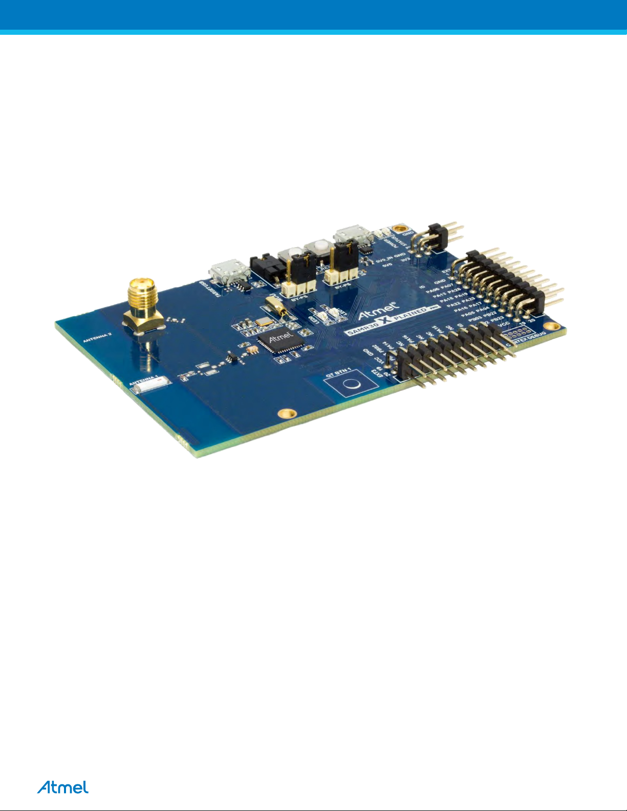
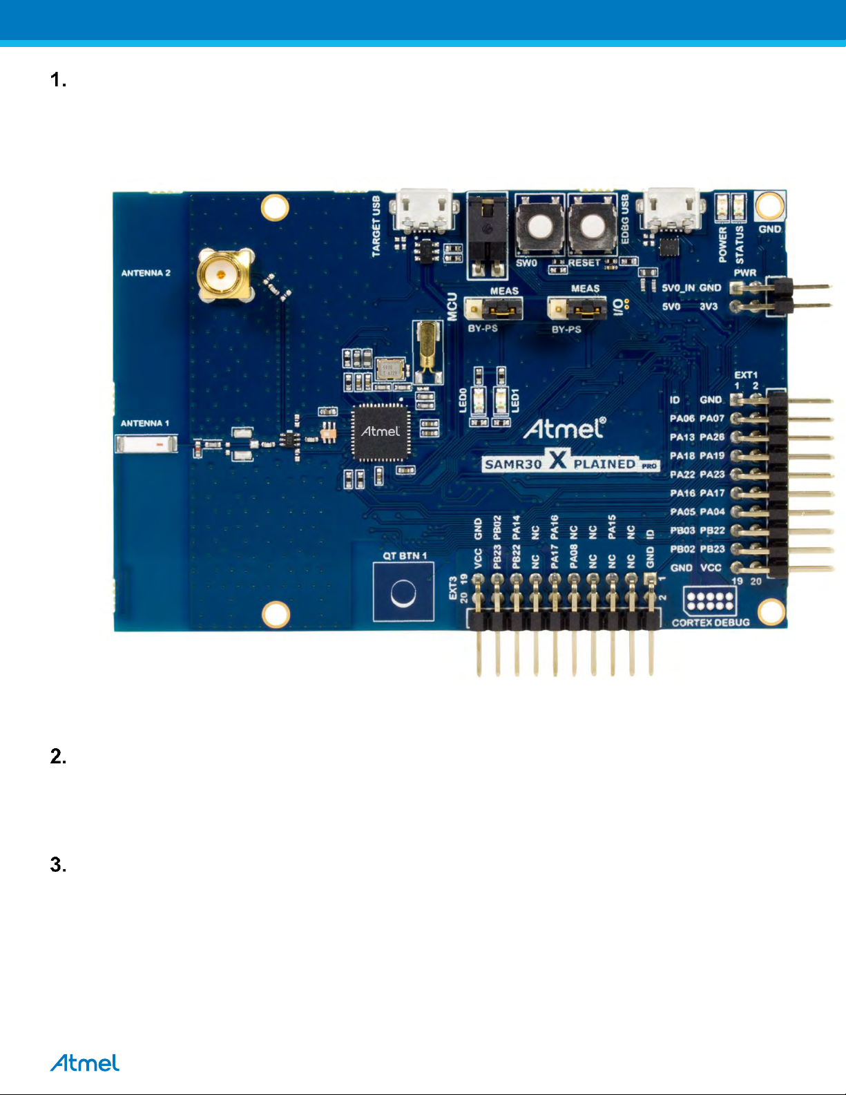
Figure 1 : Atmel ATSAMR30-XPRO Board
Hardware Setup
ATSAMR30-XPRO Boards
2.1. - 2 Nos
2.2. Micro USB cable - 2 Nos
Note: SMA cables not included in the box
Software Setup
3.1. Atmel Studio 7 (
3.2. Wireless Composer
ATSAMR30-XPRO
3.3. Drivers - Installed automatically
3.4.
ATSAMR30-XPRO Performance Analyzer firmware flash-Install if required
3.5.
ATSAMR30-XPRO Part Pack Intallation
no need to install again if it is already available in Test PC)
3
Page 4
Software Installation
4.1. Atmel Studio 7 Installation
Note: If Atmel Studio 7 is already available in Test PC, jump to step 4.2 in this section and install wireless composer
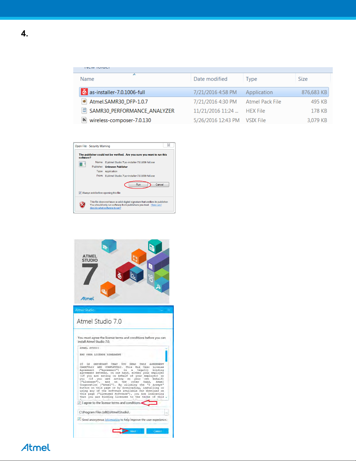
4.1.1. Open the DVD containing the Atmel Studio 7 Software package.
4.1.2. Double click the “as-installer-7.0.1006-full.exe” icon to launch Atmel Studio Installation.
4.1.3. Click Run icon.
4.1.4. Once you clicked the Run icon,the Atmel Studio 7 installer Wizard dialog box opens and agree the
licence terms and conditions.Then click “Next”
4
Page 5
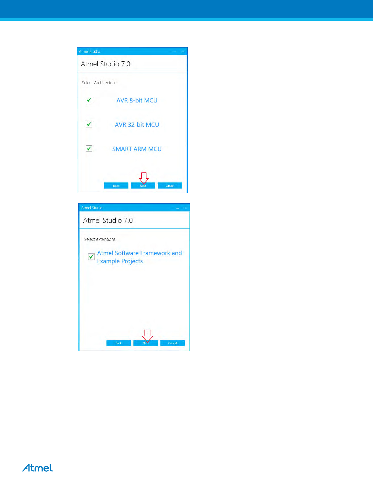
4.1.5. Ensure all the Architectires are selected and click “Next”.
4.1.6. Select ASF extensions and click “Next”
4.1.7. Click “Next”,ignore if any video card driver error shows,
5
Page 6
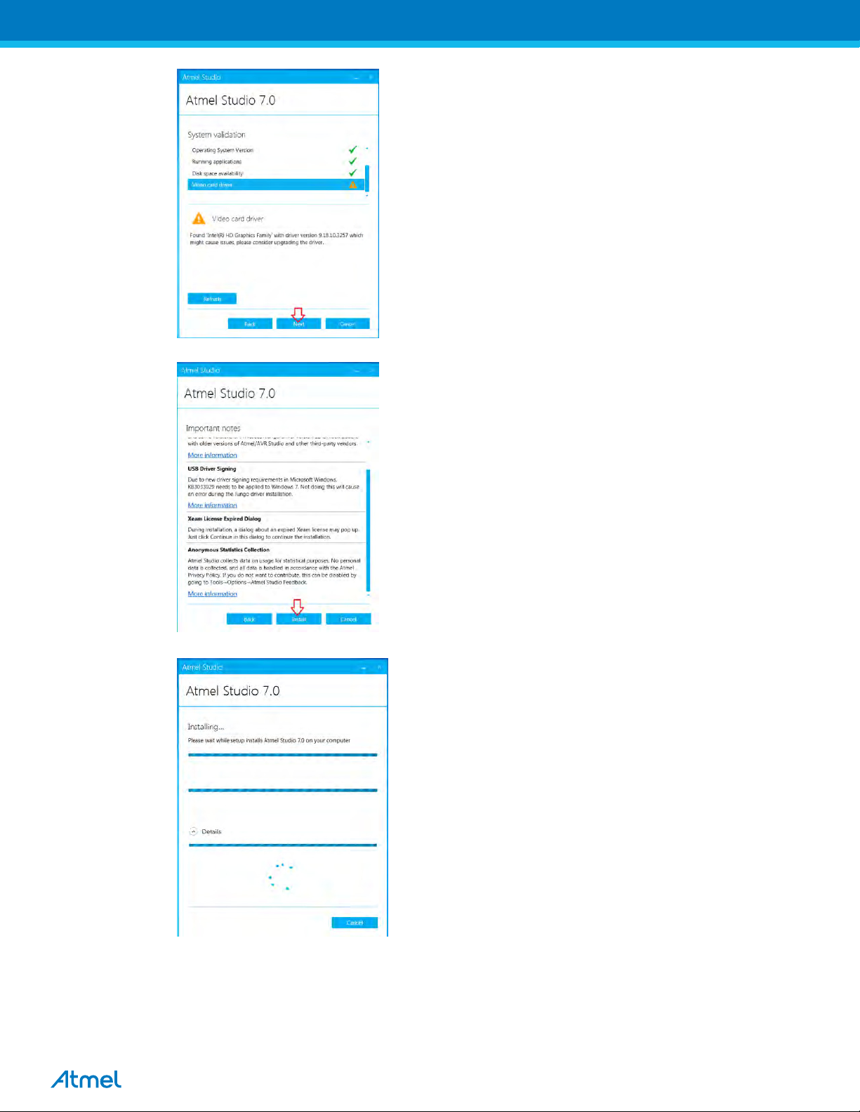
4.1.8. Click “Install”.
4.1.9. Atmel Studio 7 installion starts and once completed click ok.
6
Page 7
4.2. Wireless Composer Installation
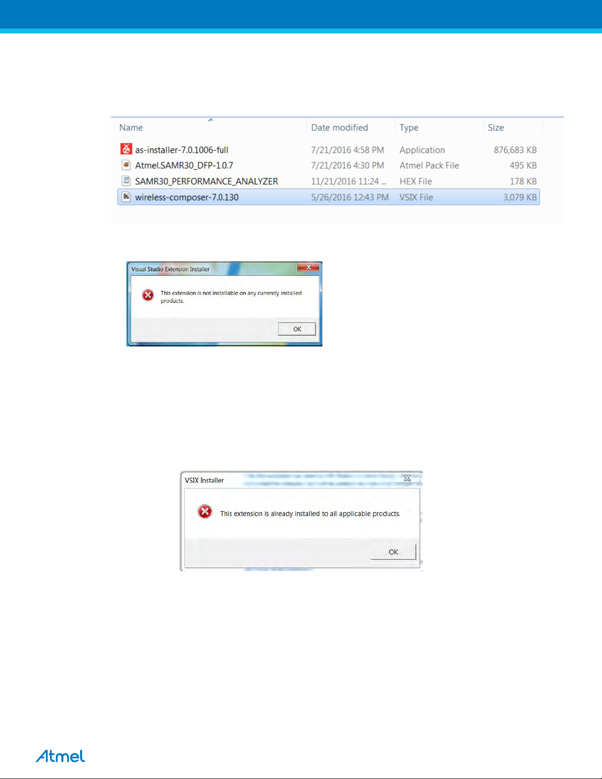
4.2.1. Next install the Wireless Composer extension by double clicking the “wireless-composer-7.0.130.vsix”
icon found in the DVD as shown in the following figure and follow the instakkation wizard to comple
the installation
Figure 2 : Wireless Composer Installation
4.2.2. In case if you I get an error message saying,
4.2.3. To overcome the above error, you have to change the file association as follows
(i) Right click on the “wireless-composer-7.0.130.vsix” file and select 'Open with', and then 'Choose default
program'.
(ii) Click the 'Browse' button (Windows 7) or click on 'More' and 'Look for another app on this PC' (Windows 8 and
newer).
(iii) Browse to VSIXInstaller.exe located in C:\Program Files (x86)\Microsoft Visual Studio 14.0\Common7\IDE
(iv) After initializing, it will pop-up as follows.Click ‘ok’ and now the installation gets completed.
7
Page 8
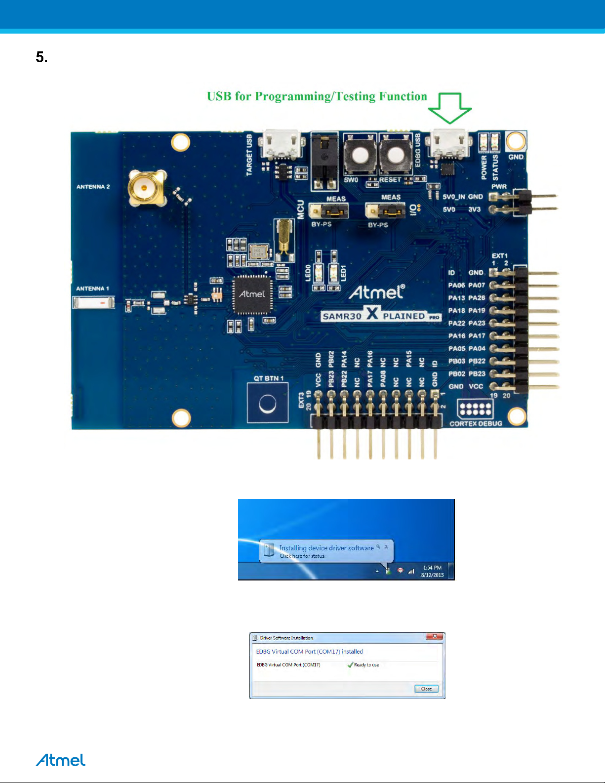
Hardware and Driver Installation (Automatic):
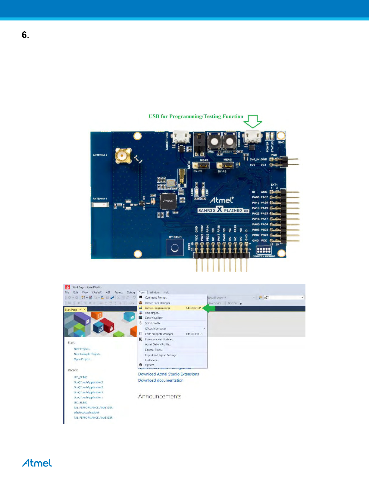
5.1. Connect a micro USB cable from PC to the micro USB port (USB for programming).
Figure.6 Hardware Setup
5.2. Next, EDBG Virtual COM port driver installation will begin automatically
Figure.7 EDBG Virtual COM PORT Driver installation
5.3. Click the taskbar notification. When the driver installation is successfully completed, there will be a
notificaion as shown below.
Figure.8 EDBG Virtual COM PORT Driver installation
Note: COM17 from the above figure is an example. The COM Port number varies depending upon the PC.
8
Page 9
Programming the hex file in SAMR30-XPRO (If required):
Board was already programmed with certification software/performance analyzer. In case if required to flash the
program file, follow the below steps.
If programming the SAMR30-Xpro board for the first time, follow the section 7(SAMR30 part pack installation) before
start programming.
6.1. Connect the SAMR30 XPRO board to the PC via EDBG micro USB connector.
* PC should have the Atmel Studio 7 installed in it
6.2. In Atmel studio,select Tools Device Programming
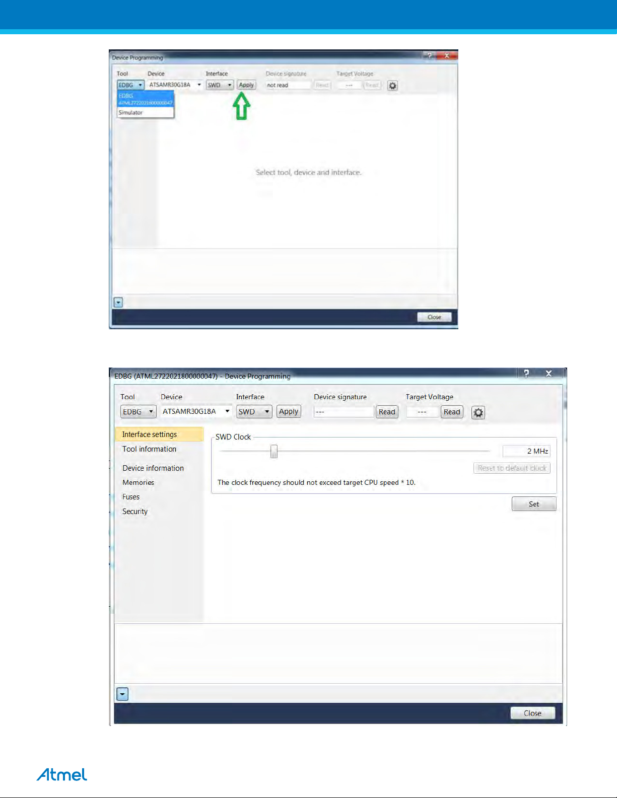
6.3. In Device Programming dialog box, select the edbg serial number and ensure the Device is “ATSAMR30G18A”
and select ‘SWD’ as Interface. Then click “Apply”
9
Page 10
In case if you noticed that the Device “ATSAMR30G18A” is unsupported,see the section 7 to overcome the error.
6.4. Once connected to the board,the device programming window will look like as follows
6.5. Read the Device signature and Target Voltage and ensure it is as follows
Device Programming: 0x1081021E
10
Page 11
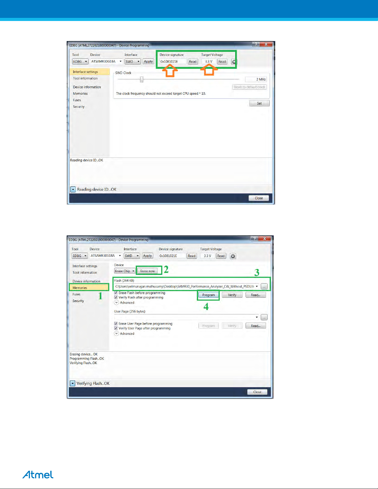
Target Volatge: 3.3V
6.6. Once ensured the device signature and Target Voltage, Click on Memories and then click “Erase now” to erase
the already existing program in the chip.
Then browse the hex file which you would like to program into the device and click Program.
6.7. Flashing the hex file in the SAMR30-XPRO board completed.
11
Page 12

SAM R30 Part Pack Intallation
Before using Atmel Studio 7 for programming/debugging in any new device/board, don’t forget to install the part pack of the
device using following steps,
7.1. Get the part pack of the device.For SAM R30, it is available in the DVD
7.2. Goto the below link
7.3. Double click on “PackManager.exe”.
7.4. Device Part Manager window opens as follows and it will list all the device part packs installed.
C:\Program Files (x86)\Atmel\Studio\7.0\atpackmanager
7.5. To install new part pack, select Install->Browse pack file and choose “DFP” pack and click install.
For SAM R30, DFP pack (*.atpack) is available in the DVD.
12
Page 13

Performance Analyzer
8.1. Launch Atmel Studio tool by clicking the Atmel Studio icon
8.2. From the Atmel Studio Start page, launch Performance Analyzer utility by clicking the icon as shown in
below figure (or) select Tools “IEEE 802.15.4 Performance Analyzer”.
Figure.9 Launch Atmel Studio 7.0
Figure.11 Atmel Studio 7.0 – Start Page
8.3. After clicking the Performance Analyzer icon, Performance Analyzer window will open as shown in the
following figure.
13
Page 14

8.4. Ensure the DUT is connected to the PC as explained in Step 1 of Section 5.
Figure.12 Performance Analyzer
14
Page 15

Connecting kit in Tx Test (Single node / CW):
CW – Continuous Wave Transmission
9.1. Select the COM Port from the dropdown menu and select a COM port to which the kit to be connected and
click “Connect”
Figure.13 Performance Analyzer – COM Port Selection
Note: COM17 from the above figure is an example. The COM Port number varies depending upon the PC.
9.2. Set the COM settings from the pop-up window. Click “Defaults” and then click “OK”
9.3. To check “transmit only” functionality; right click on the Kit information area select “Continue as a single node”.
This setting is used for continuous transmission.
15
Page 16

Figure.14 Performance Analyzer – Kit Information
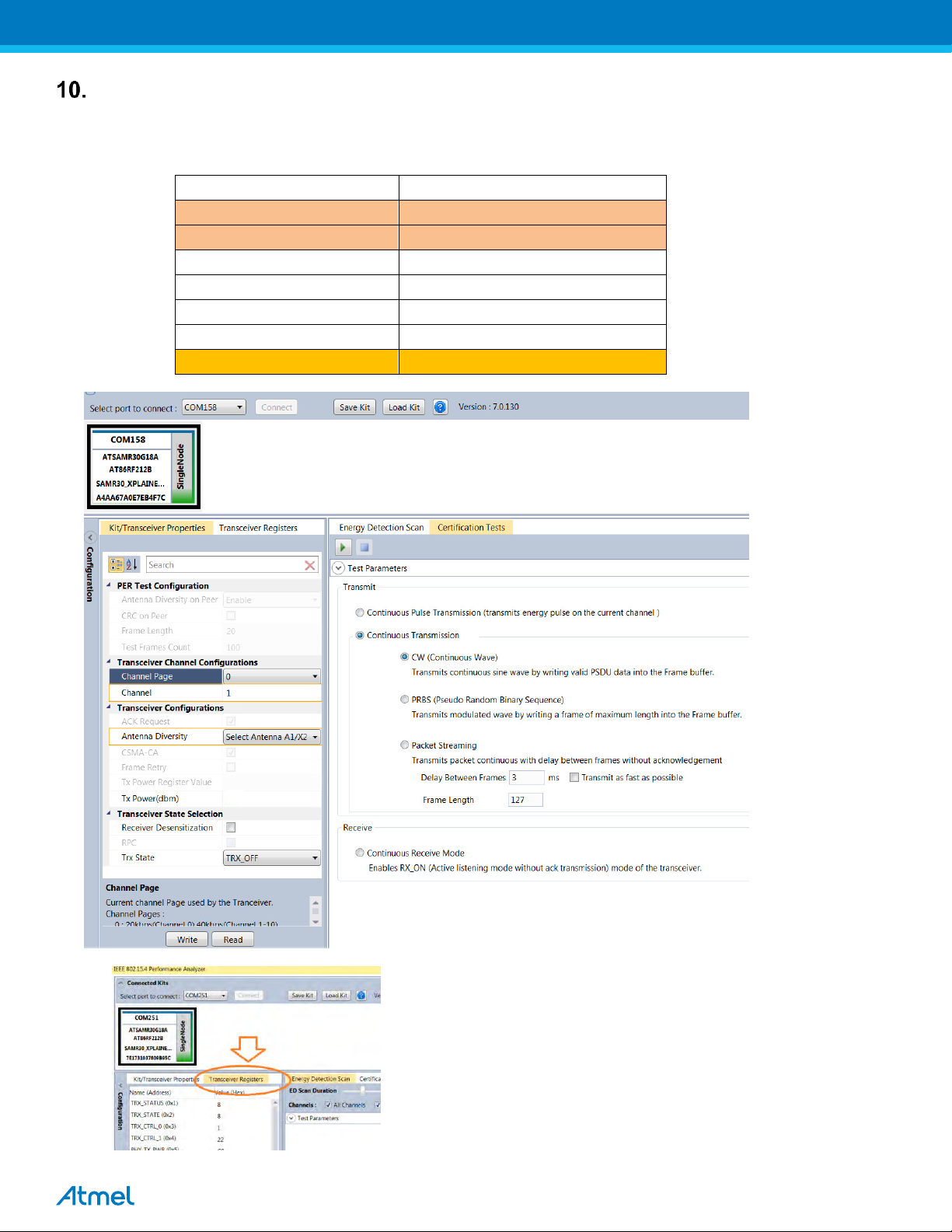
9.4. Kit / Transceiver properties, Channel Page, Channel Number, Antenna Selection and Power level can also be
changed in the Performance Analyzer window.
Antenna Diversity on Peer Enable
CRC on Peer
CRC on Peer
Frame length
Test Frames Count 100
ACK Request
CSMA CA
Frame Retry
Tx Power Register Value
20
7
16
Page 17

7
7
Figure.15 Performance Analyzer – Transceiver configuration
9.5. To Transmit CW mode or PRBS mode, click on Certification tab and Continuous transmission and CW or
PRBS.
17
Page 18

7
Figure.16 Performance Analyzer – Continuous Tx mode configuration
7
18
Page 19
Performance Analyzer Parameter
Setting
Channel Page
0
Channel
1 to 10
Antenna Diversity
Select Anetnna A1/X2
Tx Power(dBm)
7
Receiver Desensitization
- (Unchecked)
Trx State
TRX_OFF
TRX_CTRL_2 (0xC)
B4
Tx Test Modes:
10.1. Tx Test (Single node / CW) for Sub-1GHz FCCTesting:
10.1.1. Operating mode #1: BPSK-40-ALT , 40kbps, 7dBm:
Connect and test the DUT in single test mode as mentioned in
Section-9 with the following configuration,
With the above setting click “write” icon and go to “Transceiver Registers” tab.
7
19
Page 20

At the bottom corner, there is an icon called “Read”, click it.
Then Change the register value of TRX_CTRL_2 (0xC) to “B4” as shown in the below image and press ‘Enter’
in keyboard
After the TRX_CTRL_2 (0xC) value changed to “B4”, click the “Write” icon and do the test.
Important Note: Everytime when you change the channel or power or channel page, we need to change the
TRX_CTRL_2 register value to “B4”.
20
Page 21

Performance Analyzer
Parameter
Setting
Channel Page
2
Channel
1 to 10
Antenna Diversity
Select Anetnna A1/X2
Tx Power(dBm)
7
Receiver Desensitization
- (Unchecked)
Trx State
TRX_OFF
10.1.2. Operating mode #2: OQPSK-SIN-250, 250kbps, 7dBm:
Connect and test the DUT in single test mode as mentioned in
Section-9 with the following configuration,
7
21
Page 22

Performance Analyzer
Parameter
Setting
Channel Page
17
Channel
1 to 10
Antenna Diversity
Select Anetnna A1/X2
Tx Power(dBm)
7
Receiver Desensitization
- (Unchecked)
Trx State
TRX_OFF
10.1.3. Operating mode #3: OQPSK-SIN-1000-SCR-ON , 1Mbps, 7dBm:
Connect and test the DUT in single test mode as mentioned in
Section-9 with the following configuration,
7
22
Page 23

Performance Analyzer
Parameter
Setting
Channel Page
0
Channel
0
Antenna Diversity
Select Anetnna A1/X2
Tx Power(dBm)
7
Receiver Desensitization
- (Unchecked)
Trx State
TRX_OFF
10.2. Tx Test (Single node / CW) for Sub-1GHz CE Testing
10.2.1. Operating Mode#4: BPSK-20, 20kbps, 7dBm:
Connect and test the DUT in single test mode as mentioned in
Section-9 with the following configuration,
7
23
Page 24

Performance Analyzer Parameter
Setting
Channel Page
2
Channel
0
Antenna Diversity
Select Anetnna A1/X2
Tx Power(dBm)
7
Receiver Desensitization
- (Unchecked)
Trx State
TRX_OFF
10.2.2. Operating Mode#5: OQPSK-SIN-RC-100, 100kbps, 7dBm:
Connect and test the DUT in single test mode as mentioned in
Section-9 with the following configuration,
7
24
Page 25

Connecting kit in Tx-Rx Test mode (Transmit and Receive test):
11.1. Connect two devices with PC by USB cables and so both are power up.
11.2. Select one COM Port and click ‘connect’ the device corresponding to that COM port is connected and select
“Initiate Peer Search” So other device connect by RF (RF Pairring). (Device connected to COM Port is
transmitter and other device is receiver)
Figure 21: Performance Analyzer – Paring devices
11.3. When both the devices are paired, the following window appears and it is ready to perform PER (Packet
Error Rate) test. Tranmitting channel, number of frames (packets), Tx Power value can be configured from the
left side of the window.
7
Figure 22: Performance Analyzer – PER Test Configuration
25
Page 26

11.4. PER test is Transmit and Receive test. Number of transmit packets can be set by changing “Test Frames
Count”
7
Figure 23: Performance Analyzer – Transmit Packets
11.5. Run Single PER Test. Test parameter window display the Transmit packets (Frames transmitted), Receive
packets (Frames received) and RSSI (receive signal strength)
7
Figure 24: Performance Analyzer – PER Test
26
Page 27

Performance Analyzer Parameter
Setting
Antenna Diversity on Peer
Select Anetnna A1/X2
CRC on Peer
- (Unchecked)
Frame Length
20
Test Frame Count
100
Channel Page
0
Channel
1 to 10
ACK Request
Checked
Antenna Diversity
Select Anetnna A1/X2
CSMA-CA
Checked
Frame Retry
Tx Power(dBm)
7
Receiver Desensitization
Trx State
TRX_CTRL_2 (0xC)
B4
TRX Test Modes:
12.1.1. Tx-Rx Test (Transmit and Receive test) for Sub-1GHz FCC Testing
12.1.2. Tx-Rx Test - Operating mode #1 : BPSK-40-ALT , 40kbps, 7dBm:
Connect and test the DUT in single test mode as mentioned in
Section-11 with the following configuration,
- (Unchecked)
- (Unchecked)
RX_AACK_ON
7
27
Page 28

With the above setting click “write” icon and go to “Transceiver Registers” tab.
At the bottom corner, there is an icon called “Read”, click it.
Then Change the register value of TRX_CTRL_2 (0xC) to “B4” as shown in the below image and press ‘Enter’
in keyboard
28
Page 29

After the TRX_CTRL_2 (0xC) value changed to “B4”, click the “Write” icon and do the test.
Important Note: Everytime when you change the channel or power or channel page, we need to
change the TRX_CTRL_2 register value to “B4”.
29
Page 30

Performance Analyzer Parameter
Setting
Antenna Diversity on Peer
Select Anetnna A1/X2
CRC on Peer
- (Unchecked)
Frame Length
20
Test Frame Count
100
Channel Page
2
Channel
1 to 10
ACK Request
Checked
Antenna Diversity
Select Anetnna A1/X2
CSMA-CA
Checked
Frame Retry
- (Unchecked)
Tx Power(dBm)
7
Receiver Desensitization
- (Unchecked)
Trx State
12.1.3. Tx-Rx Test - Operating mode #2: OQPSK-SIN-250, 250kbps, 7dBm:
Connect and test the DUT in single test mode as mentioned in
RX_AACK_ON
Section-11 with the following configuration,
7
30
Page 31

Performance Analyzer Parameter
Setting
Antenna Diversity on Peer
Select Anetnna A1/X2
CRC on Peer
- (Unchecked)
Frame Length
20
Test Frame Count
100
Channel Page
17
Channel
1 to 10
ACK Request
Checked
Antenna Diversity
Select Anetnna A1/X2
CSMA-CA
Checked
Frame Retry
- (Unchecked)
Tx Power(dBm)
7
Receiver Desensitization
- (Unchecked)
Trx State
12.1.4. Tx-Rx Test - Operating mode #3: OQPSK-SIN-1000-SCR-ON, 1Mbps, 7dBm:
Connect and test the DUT in single test mode as mentioned in
RX_AACK_ON
Section-11 with the following configuration,
7
31
Page 32

Performance Analyzer
Parameter
Setting
Antenna Diversity on Peer
Select Anetnna A1/X2
CRC on Peer
- (Unchecked)
Frame Length
20
Test Frame Count
100
Channel Page
0
Channel
0
ACK Request
Checked
Antenna Diversity
Select Anetnna A1/X2
CSMA-CA
Checked
Frame Retry
- (Unchecked)
Tx Power(dBm)
Receiver Desensitization
Trx State
12.2. Tx-Rx Test (Transmit and Receive test) for Sub-1GHz CE Testing
12.2.1. Tx-Rx Test - Operating Mode#4: BPSK-20, 20kbps, 7dBm:
Connect and test the DUT in single test mode as mentioned in
7
- (Unchecked)
RX_AACK_ON
Section-11 with the following configuration,
7
32
Page 33

Performance Analyzer
Parameter
Setting
Antenna Diversity on Peer
Select Anetnna A1/X2
CRC on Peer
- (Unchecked)
Frame Length
20
Test Frame Count
100
Channel Page
2
Channel
0
ACK Request
Checked
Antenna Diversity
Select Anetnna A1/X2
CSMA-CA
Checked
Frame Retry
Tx Power(dBm)
7
Receiver Desensitization
Trx State
12.2.2. Tx-RxTest - Operating Mode#5: OQPSK-SIN-RC-100, 100kbps,7dBm:
Connect and test the DUT in single test mode as mentioned in
- (Unchecked)
- (Unchecked)
RX_AACK_ON
Section-11 with the following configuration,
7
33
Page 34

FCCCaution:
Any Changes or modifications not expressly approved by the party responsible for
compliancecouldvoidtheuser’sauthoritytooperatetheequipment.
This device complies with part 15 of the FCC Rules. Operation is subject to the
followingtwoconditions:(1)Thisdevicemaynotcauseharmfulinterference,and(2)
this device must accept any interference received, including interference that may
causeundesiredoperation.
This module is intended for OEM integrator. The OEM integrator is still responsible
for the FCC compliance requirement of the end product, which integrates this
module.Thefinal end product must be labeledina visible area with thefollowing”
ContainsFCCID:VM4A092722
FCCRadiationExposureStatement:
This equipment complies with FCC radiation exposure limits set forth for
uncontrolled environment .Thi s equipment should be installed and operated with
minimumdistance20cmbetweentheradiator&yourbody.Thistransmittermustnot
beco‐locatedoroperatinginconjunctionwithanyotherantennaortransmitter.
34
Page 35

© 2016 Atmel Corporation. All rights reserved. / Rev.: 0.1
Atmel®, Atmel logo and combinations thereof, Enabling Unlimited Possibilities®, QTouch®, and others are registered trademarks or trademarks of Atmel
Corporation or its subsidiaries. ARM®, Cortex™ and others are registered trademarks or trademarks of ARM Ltd. Other terms and product names may be
trademarks of others.
Disclaimer: The information in this document is provided in connection with Atmel products. No license, express or implied, by estoppel or otherwise, to any intellectual property right is granted by this
document or in connection with the sale of Atmel products. EXCEPT AS SET FORTH IN THE ATMEL TERMS AND CONDITIONS OF SALES LOCATED ON THE ATMEL WEBSITE, ATMEL ASSUMES
NO LIABILITY WHATSOEVER AND DISCLAIMS ANY EXPRESS, IMPLIED OR STATUTORY WARRANTY RELATING TO ITS PRODUCTS INCLUDING, BUT NOT LIMITED TO, THE IMPLIED
WARRANTY OF MERCHANTABILITY, FITNESS FOR A PARTICULAR PURPOSE, OR NON-INFRINGEMENT. IN NO EVENT SHALL ATMEL BE LIABLE FOR ANY DIRECT, INDIRECT,
CONSEQUENTIAL, PUNITIVE, SPECIAL OR INCIDENTAL DAMAGES (INCLUDING, WITHOUT LIMITATION, DAMAGES FOR LOSS AND PROFITS, BUSINESS INTERRUPTION, OR LOSS OF
INFORMATION) ARISING OUT OF THE USE OR INABILITY TO USE THIS DOCUMENT, EVEN IF ATMEL HAS BEEN ADVISED OF THE POSSIBILITY OF SUCH DAMAGES. Atmel makes no
representations or warranties with respect to the accuracy or completeness of the contents of this document and reserves the right to make changes to specifications and products descriptions at any time
without notice. Atmel does not make any commitment to update the information contained herein. Unless specifically provided otherwise, Atmel products are not suitable for, and shall not be used in,
automotive applications. Atmel products are not intended, authorized, or warranted for use as components in applications intended to support or sustain life.
Atmel Corporation
1600 Technology Drive
San Jose, CA 95110
USA
Tel: (+1)(408) 441-0311
Fax: (+1)(408) 487-2600
www.atmel.com
Atmel Asia Limited
Unit 01-5 & 16, 19F
BEA Tower, Millennium City 5
418 Kwun Tong Road
Kwun Tong, Kowloon
HONG KONG
Tel: (+852) 2245-6100
Fax: (+852) 2722-1369
Atmel Munich GmbH
Business Campus
Parkring 4
D-85748 Garching b. Munich
GERMANY
Tel: (+49) 89-31970-0
Fax: (+49) 89-3194621
Atmel Japan G.K.
16F Shin-Osaki Kangyo Bldg.
1-6-4 Osaki, Shinagawa-ku
Tokyo 141-0032
JAPAN
Tel: (+81)(3) 6417-0300
Fax: (+81)(3) 6417-0370
35
 Loading...