

Page 1

TITLE: SAMR21ZLL-EK User Guide
NUMBER: HWDR1-001
PAGE: 1 of 10
SAMR21ZLL-EK
User guide
Product User Guide Page 1 of 10 Template Revision: 1
Live Revision: 2
ATMEL CONFIDENTIAL
Page 2

TITLE: SAMR21ZLL-EK User Guide
NUMBER: HWDR1-001
PAGE: 2 of 10
Table of Contents
1 INTRODUCTION ................................................................................................. 3
2 CONNECTING THE KIT ..................................................................................... 3
2.1 Top View of the Kit ...................................................................................................3
2.2 USB Connection ........................................................................................................3
2.3 Jumper settings .........................................................................................................3
2.4 Connecting MS147 for conductive RF measurements .............................................3
3. SOFTWARE INSTALLATION ............................................................................. 4
4. HARDWARE AND DRIVER INSTALLATION ..................................................... 5
5. PERFORMANCE ANALYZER ............................................................................ 5
6. TX TEST (SINGLE NODE / CONTINUOUS TRANSMISSION (CW/PRBS)) ...... 6
7. TX TEST - LEGACY O-QPSK, 4DBM ................................................................ 8
8. RX TEST (TRANSMIT AND RECEIVE TEST) .................................................... 9
Product User Guide Page 2 of 10 Template Revision: 1
Live Revision: 2
ATMEL CONFIDENTIAL
Page 3
TITLE: SAMR21ZLL-EK User Guide
NUMBER: HWDR1-001
PAGE: 3 of 10
1 Introduction
This document explains how to get started using ATSAMR21ZLL-EK hardware and connect
to Atmel studio for program download.
2 Connecting the Kit
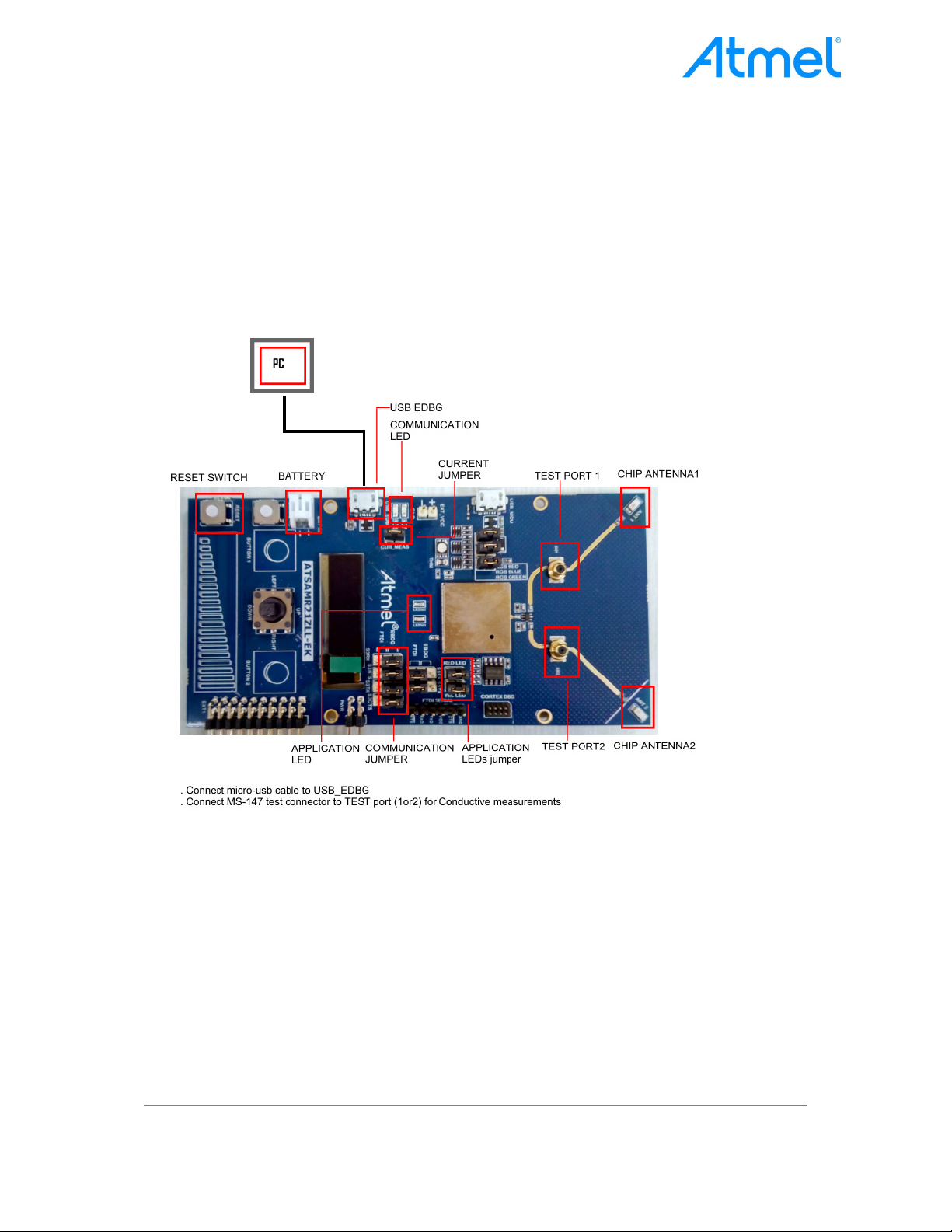
2.1 Top View of the Kit
Figure 1 : ATSAMR21ZLL – Kit Description
2.2 USB Connection
Connect micro USB cable to USB_EDBG of the EK board.
2.3 Jumper settings
As highlighted, populate current jumper, Communication jumper and Application LED
jumpers
2.4 Connecting MS147 for conductive RF measurements
Connect MS147 SMA Adaptor to either of the test ports (Port 1 or Port 2) for RF
measurements. Port1 or Port2 can be chosen from performance analyser.
Product User Guide Page 3 of 10 Template Revision: 1
Live Revision: 2
ATMEL CONFIDENTIAL
Page 4
TITLE: SAMR21ZLL-EK User Guide
NUMBER: HWDR1-001
PAGE: 4 of 10
3. Software Installation
Note: If Atmel Studio 6.2.1502 and Performance Analyzer have been already installed in Test
PC, Skip this software installation step
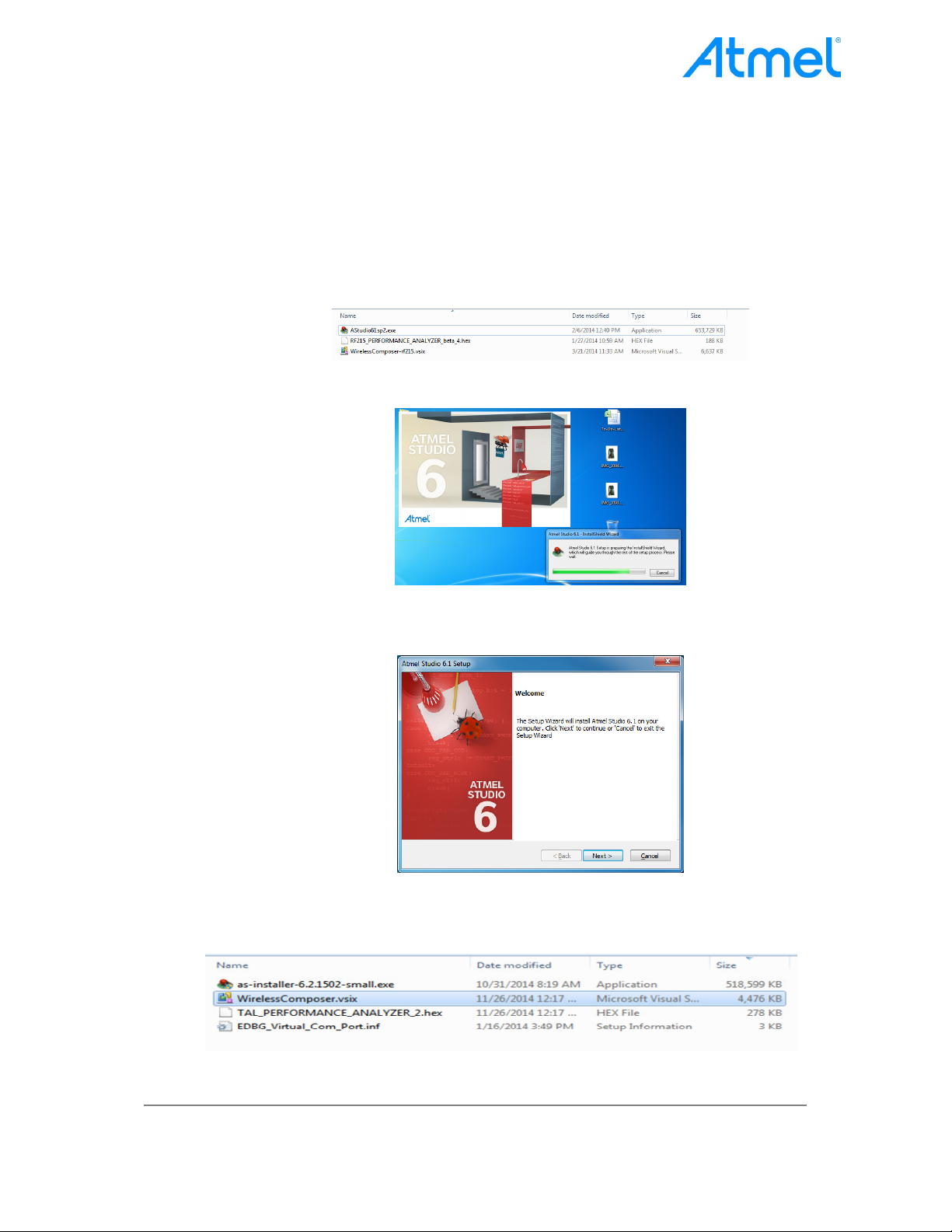
1. Open the DVD containing the Atmel Studio 6.2 Software package
2. Click the “as-installer-6.2.1502-full.exe” file to launch Atmel Studio Installation.
Figure 2 : Atmel Studio Installer
3. Now, Atmel Studio installation begins
Figure 3: Atmel Studio Installation
4. Follow the on-screen instructions to complete the installation
Figure 4: Atmel Studio Installation
5. Next install the Wireless Composer extension by clicking the “WirelessComposer.vsix”
file in the DVD as shown in the following figure.
Figure 5: Wireless Composer Installation
Product User Guide Page 4 of 10 Template Revision: 1
Live Revision: 2
ATMEL CONFIDENTIAL
Page 5

TITLE: SAMR21ZLL-EK User Guide
NUMBER: HWDR1-001
PAGE: 5 of 10
4. Hardware and Driver Installation
1. Connect a micro USB cable to USB_EDBG port of ATSAMR21ZLL-EK board.
2. Connect the other end of the USB cable to one of the PC’s USB Port
3. Now the EDBG Virtual COM port driver installation will begin automatically
Figure 6: EDBG Virtual COM PORT Driver installation
4. Click the taskbar notification. When the driver installation is successfully completed,
there will be a notification as shown in the figure.
Figure 7: EDBG Virtual COM PORT Driver installation
Note: COM17 in the above figure is for an example. The COM Port number varies from PC to PC.
5. Performance Analyzer
1. Launch Atmel Studio Tool by clicking the Atmel Studio icon
Figure 8: Launch Atmel Studio 6.2
2. For the First Time launch, studio will show the below error for Wireless Composer. Click
Ok and studio will be launched
Figure 9: Wireless composer Error
3. From the Atmel Studio Start page, Open Performance Analyzer utility by clicking the icon
as shown from the following figure.
Product User Guide Page 5 of 10 Template Revision: 1
Live Revision: 2
ATMEL CONFIDENTIAL
Page 6

TITLE: SAMR21ZLL-EK User Guide
NUMBER: HWDR1-001
PAGE: 6 of 10
Figure 10: Atmel Studio 6.2 – Start Page
4. After clicking the Performance Analyzer icon, Performance Analyzer window will open as
shown below.
Figure 11: Performance Analyzer
5. Ensure the hardware is connected to the PC as explained in the section2
6. Tx Test (Single node / Continuous Transmission (CW/PRBS))
1. Select the COM Port from the dropdown menu to which the kit is connected and click
“Connect”
Product User Guide Page 6 of 10 Template Revision: 1
Live Revision: 2
ATMEL CONFIDENTIAL
Page 7

TITLE: SAMR21ZLL-EK User Guide
NUMBER: HWDR1-001
PAGE: 7 of 10
Figure 12: Performance Analyzer – COM Port Selection
Note: COM17 in the above figure is for an example. The COM Port number varies from PC to PC.
2. Set the COM port settings from the pop-up window. Click “Defaults” and then click “OK”
3. To check the transmission only, right click on the Kit information area select “Continue as a
single node”. This is also used for continuous transmission. Refer encircled portion in
Figure 12.
4. Kit / Transceiver properties, Channel Page, channel Number and Power level can also be
changed in the Performance Analyzer window. Refer steps 1 to 3 in Figure 13
5. TX power register values to change transmit power. Refer Step 4 in Figure 13
6. To Transmit CW mode or PRBS mode, click on Continuous transmission and select
continuous transmission CW or PRBS. Refer step 5 in Figure 13
Product User Guide Page 7 of 10 Template Revision: 1
Live Revision: 2
ATMEL CONFIDENTIAL
Page 8

TITLE: SAMR21ZLL-EK User Guide
NUMBER: HWDR1-001
PAGE: 8 of 10
Figure 13: Performance Analyzer – Continuous mode configuration
7. Tx Test - legacy O-QPSK, 4dBm
1. Performance Analyzer configuration settings are
Table 1: Performance analyser settings for Legacy O-QPSK
Channel 11 to 26 (2405MHz to 2480MHz)
Channel Page 0
Tx Power (dBm) 4
Click to start Transmission
Click to stop Transmission
`
Figure 14: O-QPSK- Continuous mode configuration
Product User Guide Page 8 of 10 Template Revision: 1
Live Revision: 2
ATMEL CONFIDENTIAL
Page 9

TITLE: SAMR21ZLL-EK User Guide
NUMBER: HWDR1-001
PAGE: 9 of 10
8. Rx Test (Transmit and Receive test)
1. Connect two devices with PC by USB cable so both are powered up.
2. Select one COM Port to which the device is connected and select “Initiate Peer Search”
So that another device can be connected by RF (RF Pairing). (Device connected to COM
Port is transmitter and other device is receiver)
Figure 15: Performance Analyzer – Paring devices
3. When both the devices are paired, the following window appears and it is ready to do PER
(Packet Error Rate) test. Also can be configured Transmitting channel, number of frames
(packets) from the left side of the window.
Figure 16: performance Analyzer – PER Test Configuration
4. PER test is Transmit receive Test, number of transmit packets can be set by changing
“Test Frames Count”
Product User Guide Page 9 of 10 Template Revision: 1
Live Revision: 2
ATMEL CONFIDENTIAL
Page 10

TITLE: SAMR21ZLL-EK User Guide
NUMBER: HWDR1-001
PAGE: 10 of 10
Figure 17: Performance Analyzer – Transmit Packets
5. Run Single PER Test. Test parameter window display the Transmit packets (Frames
transmitted), Receive packets (Frames received) and RSSI (received signal strength)
Figure 18: Performance Analyzer – PER Test
Product User Guide Page 10 of 10 Template Revision: 1
Live Revision: 2
ATMEL CONFIDENTIAL
Page 11

FCC Warning:
Any Changes or modifications not expressly approved by the party responsible for compliance
could void the user's authority to operate the equipment.
This device complies with part 15 of the FCC Rules. Operation is subject to the following two
conditions: (1) Thi s devi ce may not cause ha rmful interferen ce, and (2) thi s device m ust
accept any interference received, including interference that may cause undesired operation.
This device has been modularly approved and is intended for use in evaluation of
ATSAMR21G18A module in Zigbee based light link application.
This e quipment co mplies with F CC radiation exposure limit s set forth fo r an un controlled
environment .
Labeling of end‐user equipment
This device has been modularly approved. The Final end product label must contain the
following statement on the product label:
“Contains FCC ID: VW4A092412’’
IC Warning:
This device complies with Industry Canada licence-exempt RSS standard(s). Operation is
subject to the following two conditions:
(1) this device may not cause interference, and
(2) this device must accept any interference, including interference that may cause undesired
operation of the device.
Le présent appareil est conforme aux CNR d'Industrie Canada applicables aux appareils radio
exempts de licence. L'exploitation est autorisée aux deux conditions suivantes :
(1) l'appareil ne doit pas produire de brouillage, et
(2) l'utilisateur de l'appareil doit accepter tout brouillage radioélectrique subi, même si le
brouillage est susceptible d'en compromettre le fonctionnement
Per RSS GEN section 3.21 requirement, The module must be labeled with its own certification number,
and, if the certification number is not visible when the module is installed inside a host d evice, then the
host device into which the module is installed must also display a label referring to the enclosed module.
Par RSS GEN section 3.21 exigence, Le module doit être étiqueté avec son propre numéro de
certification, et, si le nombre de certification ne est pas visible lorsque le module est installé à
l'intérieur d'un dispositif hôte, alors le dispositif hôte dans laquelle le mo dule est installé doit
également afficher un label faisant référence au module ci-joint.
This e quipment co mplies with
environment
IC radiation exp
osure limit s set forth fo r an un controlled
Cet équipement est conforme aux limites IC d'exposition aux radiations définies pour un
environnement non contrôlé.
Labeling of end‐user equipment
Page 12

This device has been modularly approved. The Final end product label must contain the
following statement on the product label:
“Contains IC: 11019A-092412
 Loading...