

Page 1
42033AVR 09/2012
APPLICATION NOTE
Atmel AVR10003: ATmega256RFR2 Evaluation Kit – Quick
Start Guide
8-bit Atmel Microcontrollers
Features
This application note briefly describes how to set up and run the pre-flashed
performance test application included with the Atmel® ATmega256RFR2.
The latest dedicated applications can be downloaded from www.atmel.com and
flashed to the kit hardware by using the serial bootloader functionality of the preflashed application.
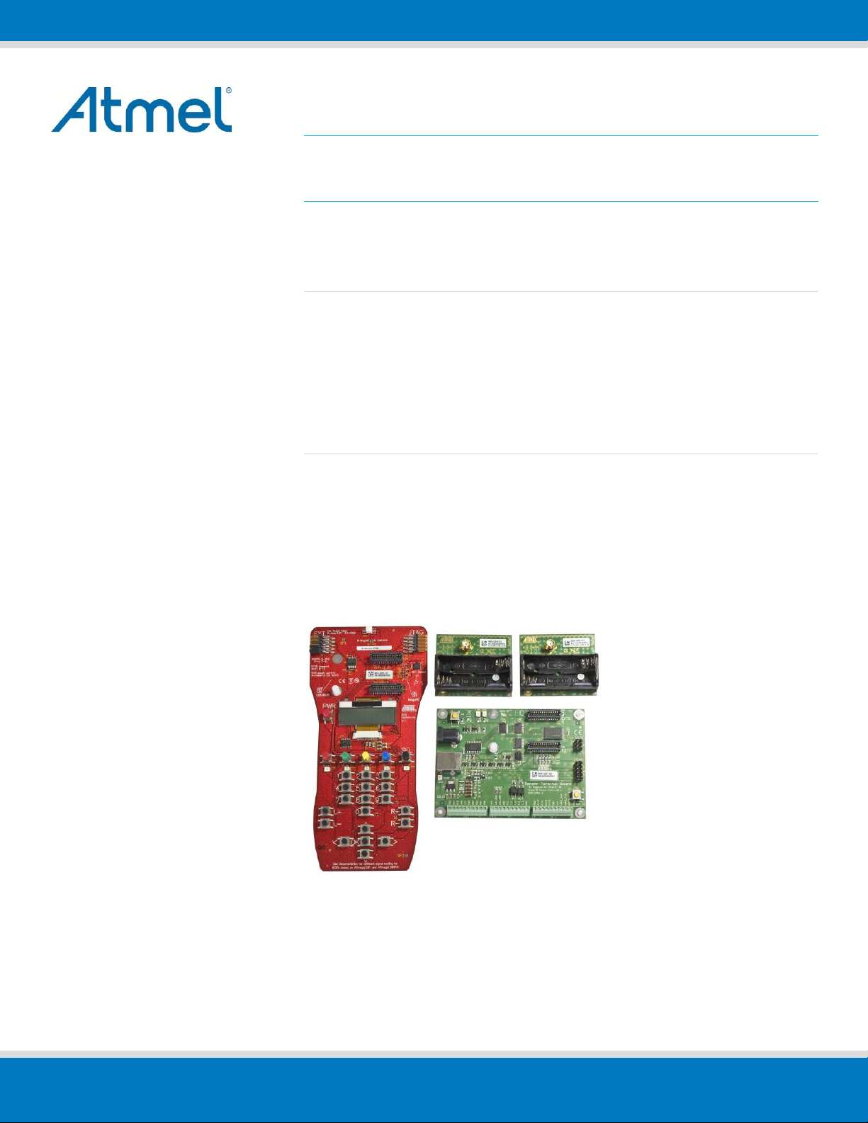
Kit contents
2x Atmel RCB256RFR2 Radio Controller Board
1x Atmel RCB Sensor Terminal Board (STB)
1x Atmel RCB Key Remote Control board
1x RCB-BB RS232 cable
1x USB cable
2x 2.4GHz antenna
4x AAA battery
1x Quick Start Guide
Page 2
2
config TX RX
status
D2 D3 D4 T1
1. Simple range measurement
The pre-flashed performance test application on the RCB256RFR2 radio controller boards features a simple range
measurement. Each board operates in a standalone manner, and is able to transmit or receive data frames. A
successful transmit or receive operation is indicated by a blinking LED.
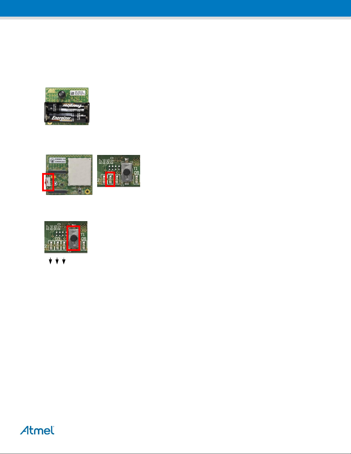
1.1 Board assembling
1. Connect the antennas to both RCBs.
2. Insert two batteries in each of the RCBs.
1.2 Power up the boards
Apply power to both RCBs by switching on the power switch located on the
top side of the board. The RCBs run a power-on check and indicate the
successful completion by switching on the second of the three LEDs.
1.3 Run simple range measurement application
Choose one of the RCB256RFR2 RCBs, and press button T1 to start the simple range
measurement application. First, the RCB initiates a connection and configuration procedure by
sending broadcast frames, and waiting for a response from the second RCB. After a successful
configuration, the RCBs turn on LED-D2 to indicate that status. Afterwards the initiator starts to
transmit data frames immediately. Each data frame transmission is indicated by blinking the TX
status LED-D3. A successful data frame reception on the second node is indicated by blinking the
RX status LED-D4.
The RX status LED stops blinking if no data frames are received, such as when, for example, the node has left the
communication range. Data frame transmission can be stopped by pressing T1 once more on the node transmitting
frames. Moreover the RCBs can transmit and receive frames simultaneously. Pressing button T1 on both nodes
initiates each node to transmit frames. The three LEDs indicate their respective functions: LED-D2 a successful
configuration, LED-D3 transmission and LED-D4 reception.
Note: The node connection and configuration gets lost when the RCBs’ power supply is switched off. To restart the simple
range measurement, power cycles both RCBs before pressing T1 on one RCB to restart the application.
2. Packet error rate measurement
The pre-flashed performance test application is also configured with packet error rate (PER) measurement functionality
(as defined in IEEE® 802.15.4), enabling the user to explore various radio transceiver features, radio transceiver
registers, and performance by tuning with customized configurations. For this application, one RCB256RFR2 RCB
needs to be connected to a PC.
Atmel AVR10003: ATmega256RFR2 Evaluation Kit – Quick Start Guide [APPLICATION NOTE]
42033AVR09/2012
Page 3

3
2.1 Board assembling
1. Switch off power drom one RCB, or remove the batteries and connect
the RCB to the STB.
2. Download the patched FT245RL driver files from the kit website, and
follow the installation guidelines on your PC to install the USB driver.
3. Connect the STB to a PC with the USB cable.
4. A successful installation and enumeration of the USB connection with
the PC is indicated by the power status LED on the STB.
2.2 Set up the terminal program on the PC
A terminal program running on the PC is used to control the application running on the RCB connected to the STB. Set
up the terminal program as follows:
BAUD RATE: 9600
PARITY: None
DATA BITS: 8
STOP BITS: 1
FLOW CONTROL: Off
2.3 Power up the boards
1. Apply the standalone RCB (optional) by turning on the power switch
on the top side of the board. The RCB runs a power-on check and
indicates the successful completion by switching on the second of
the three LEDs.
2. The RCB mounted on the STB is powered via the USB connection.
Make sure that the batteries are removed or that the power switch is
in the off position.
2.4 Run the packet error rate measurement
Type any character in the terminal window to initiate the configure procedure for both RCB nodes and show the menu.
Optionally, if no peer node is active, the search for a peer device can be aborted by pressing ENTER. The node gets
configured for stand-alone operation. The packet error rate measurement can be operated through the menu options
displayed on the UART terminal program. A detailed description of the menu options can be found in the
ATmega256RFR2 Evaluation Kit – User Guide.
3. Serial bootloader
The application offers serial bootloader functionality to flash other applications to the RCBs. A detailed description on
the usage of the bootloader can be found in the Atmel AVR2054 Serial Bootloader - User Guide.
Atmel AVR10003: ATmega256RFR2 Evaluation Kit – Quick Start Guide [APPLICATION NOTE]
42033AVR09/2012
Page 4

4
4. Agency Certification
4.1 UNITED STATES (FCC)
This equipment complies with Part 15 of the FCC rules and regulations. To fulfill FCC Certification requirements, an
OEM manufacturer must comply with the following regulations:
1. The RCB256RFR2 limited modular transmitter must be labeled with its own FCC ID number, and, if the FCC ID
is not visible when the module is installed inside another device, then the outside of the device into which the
module is installed must also display a label referring to the enclosed module. This exterior label can use
wording such as the following:
Contains FCC ID: VW4A091786 The enclosed device complies with Part 15 of the FCC Rules. Operation is
subject to the following two conditions: (i.) this device may not cause harmful interference and (ii.) this device
must accept any interference received, including interference that may cause undesired operation.
Any similar wording that expresses the same meaning may be used.
WARNING: The Original Equipment Manufacturer (OEM) must ensure that the OEM limited modular
transmitter must be labeled with its own FCC ID number. This includes a clearly visible label on the outside of
the final product enclosure that displays the contents shown below. If the FCC ID is not visible when the
equipment is installed inside another device, then the outside of the device into which the equipment is
installed must also display a label referring to the enclosed equipment.
IMPORTANT: This equipment complies with Part 15 of the FCC Rules. Operation is subject to the following two
conditions: (1) this device may not cause harmful interference, and (2) this device must accept any interference
received, including interference that may cause undesired operation (FCC 15.19).
The internal / external antenna(s) used for this mobile transmitter must provide a separation distance of at least 20 cm
from all persons and must not be colocated or operating in conjunction with any other antenna or transmitter.
Installers must be provided with antenna installation instructions and transmitter operating conditions for satisfying RF
exposure compliance. This device is approved as a mobile device with respect to RF exposure compliance, and may
only be marketed to OEM installers. Use in portable exposure conditions (FCC 2.1093) requires separate equipment
authorization.
IMPORTANT: Modifications not expressly approved by this company could void the user's authority to operate this
equipment (FCC section 15.21).
IMPORTANT:
The FCC ID for the module is valid only under the following conditions:
- The Antenna supplied with the module is used (the antenna shown in the filing)
- The Antenna must not be in the user accessible area of the final host device. (This means the antenna must not be
accessible from the battery compartment.)
Atmel AVR10003: ATmega256RFR2 Evaluation Kit – Quick Start Guide [APPLICATION NOTE]
42033AVR09/2012
Page 5

5
This equipment has been tested and found to comply with the limits for a Class A digital device, pursuant to Part 15 of
the FCC Rules. These limits are designed to provide reasonable protection against harmful interference when the
equipment is operated in a commercial environment. This equipment generates, uses, and can radiate radio frequency
energy and, if not installed and used in accordance with the instruction manual, may cause harmful interference to radio
communications. Operation of this equipment in a residential area is likely to cause harmful interference in which case
the user will be required to correct the interference at his own expense (FCC section 15.105).
4.2 European Union (ETSI)
The RCB256RFR2 Modules has been certified for use in European Union countries. If these modules are incorporated
into a product, the manufacturer must ensure compliance of the final product to the European harmonized EMC and
lowvoltage/safety standards. A Declaration of Conformity must be issued for each of these standards and kept on file as
described in Annex II of the R&TTE Directive.
Furthermore, the manufacturer must maintain a copy of the modules' documentation and ensure the final product does
not exceed the specified power ratings, antenna specifications, and/or installation requirements as specified in the user
manual. If any of these specifications are exceeded in the final product, a submission must be made to a notified body
for compliance testing to all required standards.
IMPORTANT: The 'CE' marking must be affixed to a visible location on the OEM product. The CE mark shall
consist of the initials "CE" taking the following form:
The CE marking must have a height of at least 5mm except where this is not possible on account of the nature of the
apparatus.
The CE marking must be affixed visibly, legibly, and indelibly.
More detailed information about CE marking requirements you can find at "DIRECTIVE 1999/5/EC OF THE
EUROPEAN PARLIAMENT AND OF THE COUNCIL" on 9 March 1999 at section 12.
Atmel AVR10003: ATmega256RFR2 Evaluation Kit – Quick Start Guide [APPLICATION NOTE]
42033AVR09/2012
Page 6

Atmel Corporation
2325 Orchard Parkway
San Jose, CA 95131
USA
Tel: (+1)(408) 441-0311
Fax: (+1)(408) 487-2600
www.atmel.com
Atmel Asia Limited
Unit 01-5 & 16, 19F
BEA Tower, Millennium City 5
418 Kwun Tong Road
Kwun Tong, Kowloon
HONG KONG
Tel: (+852) 2245-6100
Fax: (+852) 2722-1369
Atmel Munich GmbH
Business Campus
Parkring 4
D-85748 Garching b. Munich
GERMANY
Tel: (+49) 89-31970-0
Fax: (+49) 89-3194621
Atmel Japan G.K.
16F Shin-Osaki Kangyo Building
1-6-4 Osaki
Shinagawa-ku, Tokyo 141-0032
JAPAN
Tel: (+81)(3) 6417-0300
Fax: (+81)(3) 6417-0370
© 2012 Atmel Corporation. All rights reserved. / Rev.: 42033AVR09/2012
Atmel®, logo and combinations thereof, Enabling Unlimited Possibilities®, AVR®, and others are registered trademarks or trademarks of Atmel Corporation or its
subsidiaries. Other terms and product names may be trademarks of others.
Disclaimer: The information in this document is provided in connection with Atmel products. No license, express or implied, by estoppel or otherwise, to any intellectual property right is granted by this
document or in connection with the sale of Atmel products. EXCEPT AS SET FORTH IN THE ATMEL TERMS AND CONDITIONS OF SALES LOCATED ON THE ATMEL WEBSITE, ATMEL ASSUMES
NO LIABILITY WHATSOEVER AND DISCLAIMS ANY EXPRESS, IMPLIED OR STATUTORY WARRANTY RELATING TO ITS PRODUCTS INCLUDING, BUT NOT LIMITED TO, THE IMPLIED
WARRANTY OF MERCHANTABILITY, FITNESS FOR A PARTICULAR PURPOSE, OR NON-INFRINGEMENT. IN NO EVENT SHALL ATMEL BE LIABLE FOR ANY DIRECT, INDIRECT,
CONSEQUENTIAL, PUNITIVE, SPECIAL OR INCIDENTAL DAMAGES (INCLUDING, WITHOUT LIMITATION, DAMAGES FOR LOSS AND PROFITS, BUSINESS INTERRUPTION, OR LOSS OF
INFORMATION) ARISING OUT OF THE USE OR INABILITY TO USE THIS DOCUMENT, EVEN IF ATMEL HAS BEEN ADVISED OF THE POSSIBILITY OF SUCH DAMAGES. Atmel makes no
representations or warranties with respect to the accuracy or completeness of the contents of this document and reserves the right to make changes to specifications and products descriptions at any time
without notice. Atmel does not make any commitment to update the information contained herein. Unless specifically provided otherwise, Atmel products are not suitable for, and shall not be used in,
automotive applications. Atmel products are not intended, authorized, or warranted for use as components in applications intended to support or sustain life.
 Loading...