

Page 1
AVRXXXX: RZ600-232 HW Manual
Features
Contains the Reference design for AT86RF232 Transceiver
Option of ordering Single Transceiver board, over ordering the entire set
found in the main RZ600 Kit.
Order as many of RZ600-232 Board alone as required.
Stub antenna included
AT32UC3A3256 based USB host boards orderable separately as
AVRRZ600-USB
Ideal for PC to RF gateways, packet sniffers and network commissioning
tools
On board ID chip for easy IEEE MAC address
1 Introduction
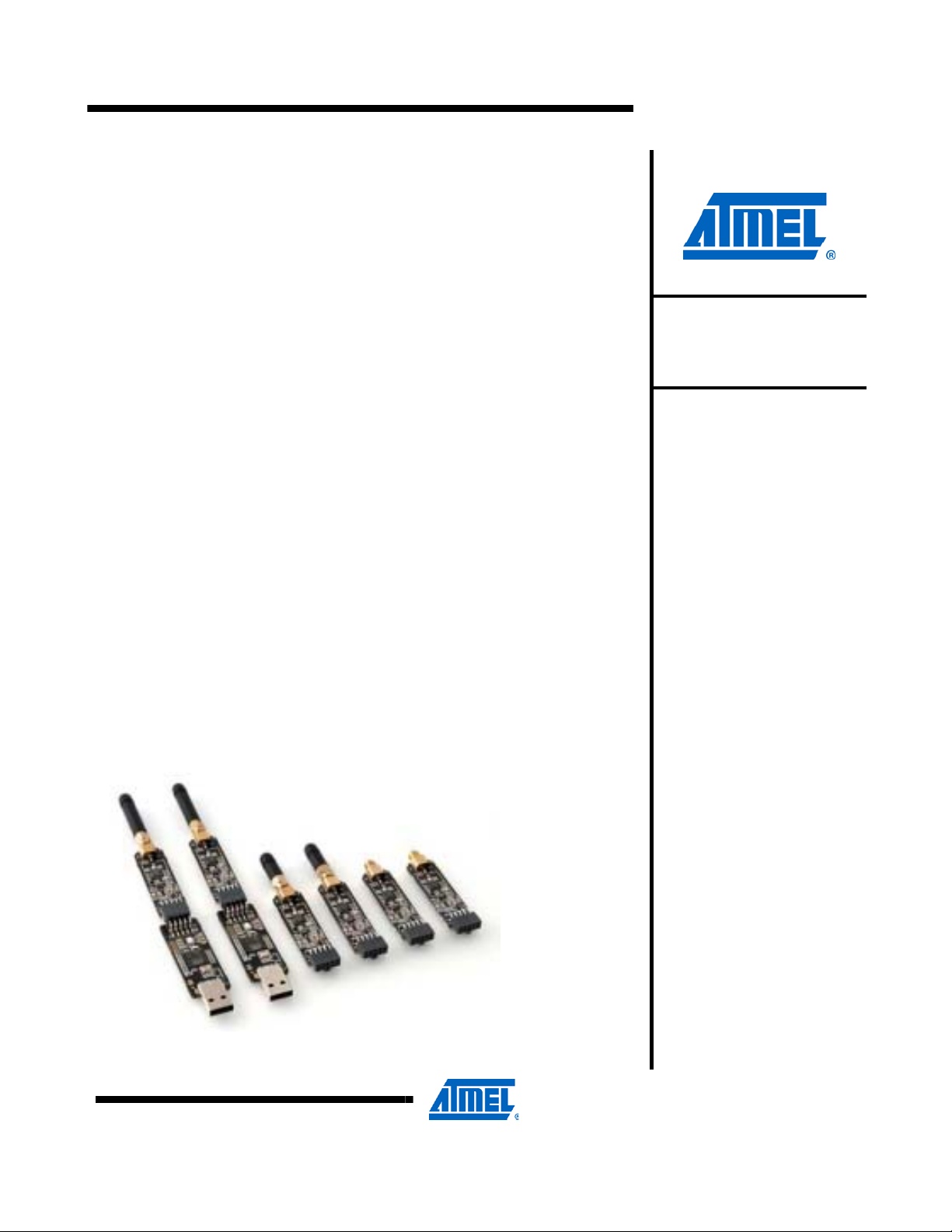
The AVRRZ600-232 Subkit is an evaluation kit for the Atmel AT86RF232 radio
frequency device. The box contains one Single RF232 2.4GHz board with the
required accessories (connectors and Antenna). These are highly acclaimed
networking devices within low power personal area networks. That being said;
this RZ600-232 radio board also sports an Atmel standardized 10-pin
connector that will enable the RF boards to be connected to any
AVR microcontroller. A wide range of the standard Atmel AVR design tools
have the host end of the standardized 10-pin connector – so as a customer of
Atmel, you are empowered to evaluate Atmel radio transceivers in virtually any
application segment. The RZ600-232 kit enables RF4CE, IEEE 802.15.4,
ZigBee® and 6lowPAN network technologies to run on the full Atmel portfolio of
low power AVR microcontrollers.
AVRRZ600-232
AVRRZ600-232
Hardware
User Manual
Figure 1-1. RZ600 HW Overview
Rev. NNNNN
Page 2
2 Related items
3 Overview
AVR32 Studio (Atmel’s free IDE)
http://www.atmel.com/dyn/products/tools_card.asp?tool_id=4116
AVR32 GNU Toolchain (Atmel’s free Compiler and Utilities)
http://www.atmel.com/dyn/products/tools_card.asp?tool_id=4118
JTAGICE mkII (On-chip programming and debugging tool)
http://www.atmel.com/dyn/products/tools_card.asp?tool_id=3353
AVR ONE! (On-chip programming and debugging tool)
http://www.atmel.com/dyn/products/tools_card.asp?tool_id=4279
FLIP 3.4.2(Flexible In System Programmer)
http://www.atmel.com/dyn/products/tools_card.asp?tool_id=3886
This section gives an overview of the RZ600-232 kit from a system perspective as
well as what the kit contains and its minimum requirements. A set of condensed
instructions are then given on how to get the evaluation application for the kit up and
running in the shortest time possible.
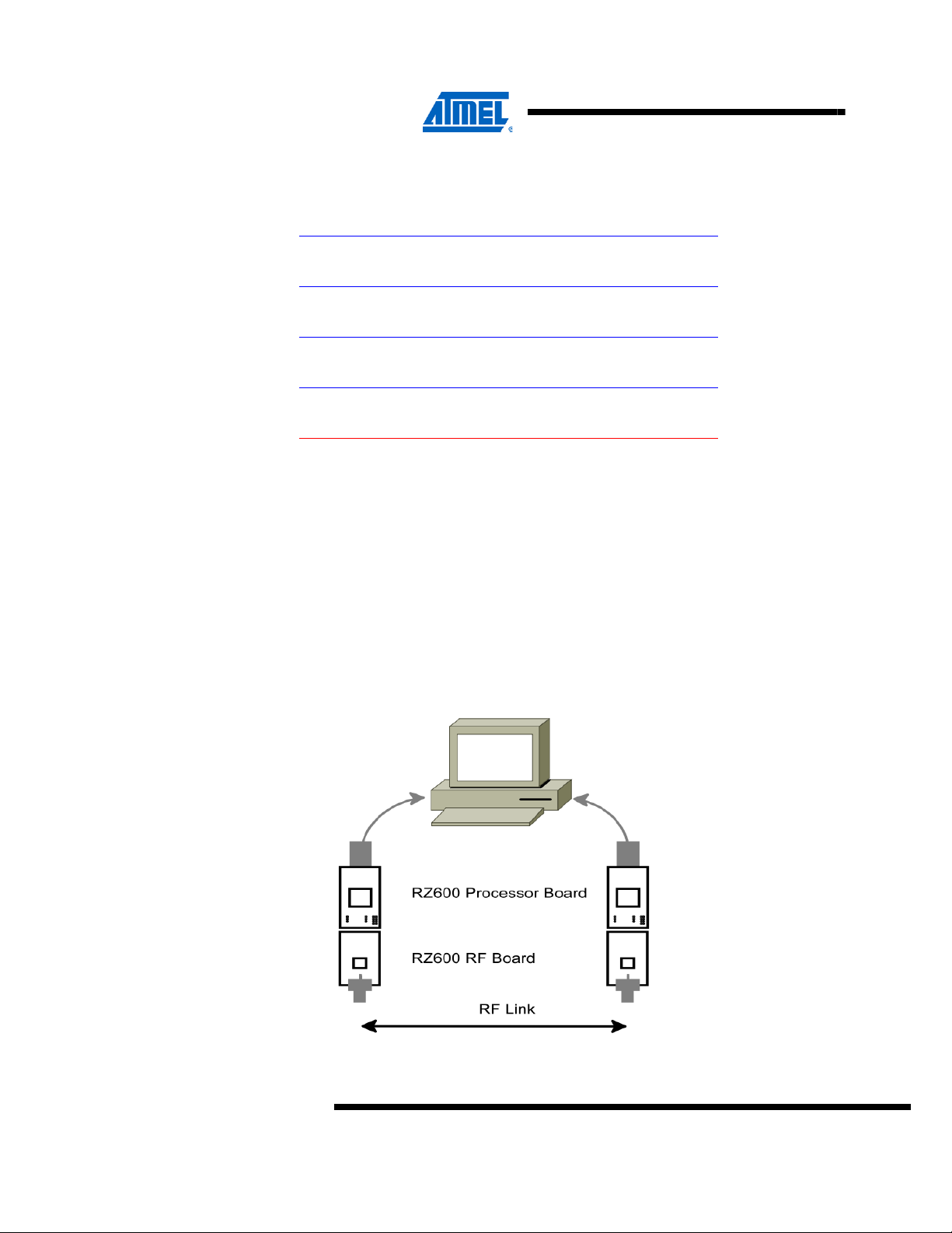
Figure 3-1 shows how the two processor boards (AVRRZ600-USB) paired with
the radio frequency boards (AVRRZ600-232) can form a wireless peer to peer data
connection over USB. The application that is pre programmed by Atmel on the
AT32UC3A3256 is indeed such a USB to RF gateway.
Figure 3-1 RZ600 used in conjunction with PC
2
AVRRZ600-232
NNNNN2
Page 3
3.1 Kit contents
3.2 System Requirements
AVRRZ600-232
The RZ600-232 kit contains the following pieces of hardware:
1 unit AT86RF232 radio board: miniature carrier board with the AT86RF2 32
radio transceiver mounted, SMA antenna connector, one wire ID chip
and Atmel standard 10-pin connector.
1 pc. 2.4GHz SMA stub antenna
1 pc. Bag with wires and squid cable: The squid cable fits the radio
frequency boards and will enable wiring to a hardware that does not
contain the standard Atmel 10-pin accessory header.
Table 3-1 contains the minimum system requirements for the RZ600 kit when
connected to a PC for application development on the AT32UC3A3256
microcontroller.
Table 3-1 Minimum System Requirements
Parameter Value Comment
Hardware
PC/CPU Intel Pentium III or
better,800 MHz
PC/RAM 128 Mbytes
PC/Video 1024×768,SVGA
PC/Hard disk free space 200 Mbytes
On-Chip Debugger &
Programmer
Software
Operating System Windows 2000/XP/Vista/7
IDE AVR 32 Studio or IAR
Programmer FLIP 3.4.2 Batch ISP command line
AVR JTAG ICE mkII or
AVR ONE!
Embedded Workbench for
Atmel AVR32
AVR JTAG ICE mkII or
AVR ONE! is required if
the user wishes to debug
and do custom application
development.
AVR 32 Studio with
compiler utilities or IAR
EWB is required for
application development
tool with FLIP 3.4.2 can be
used for reprogramming
the processor board
controller
3.3 Quick Start Guide
NNNNN
RZ600 processor board – RZ600-USB is programmed for AT86RF231 radio boards in
the factory. For using the AT86RF232 transceiver boards, processor board needs to
be reprogrammed. Refer section “7.5.2 Bootloader Programming using BatchISP”
and “Table 6-1 Firmware layout” table for programming the processor board using
preprogrammed boot loader available on the processor board controller. The
following sequence is suggested when testing the evaluation application on the
RZ600-232 kit:
1. Unpack the kit and verify contents
2. Connect 2 RZ600-232 boards each to 2 RZ600-USB boards.
3
Page 4

3. Connect the RF Board to the appropriate antenna. Refer Section 4.3 for selecting
4. Insert the assembly into a free USB port on the computer.
5. Let the devi ces enumerate – they s hould become availa ble as two CDC virtua l
6. Open two terminal windows and start typing. Verify that the text in the two
4 Hardware Description
This chapter walks through the different pieces of hardware that you will find in the
RZ600 kit in greater detail.
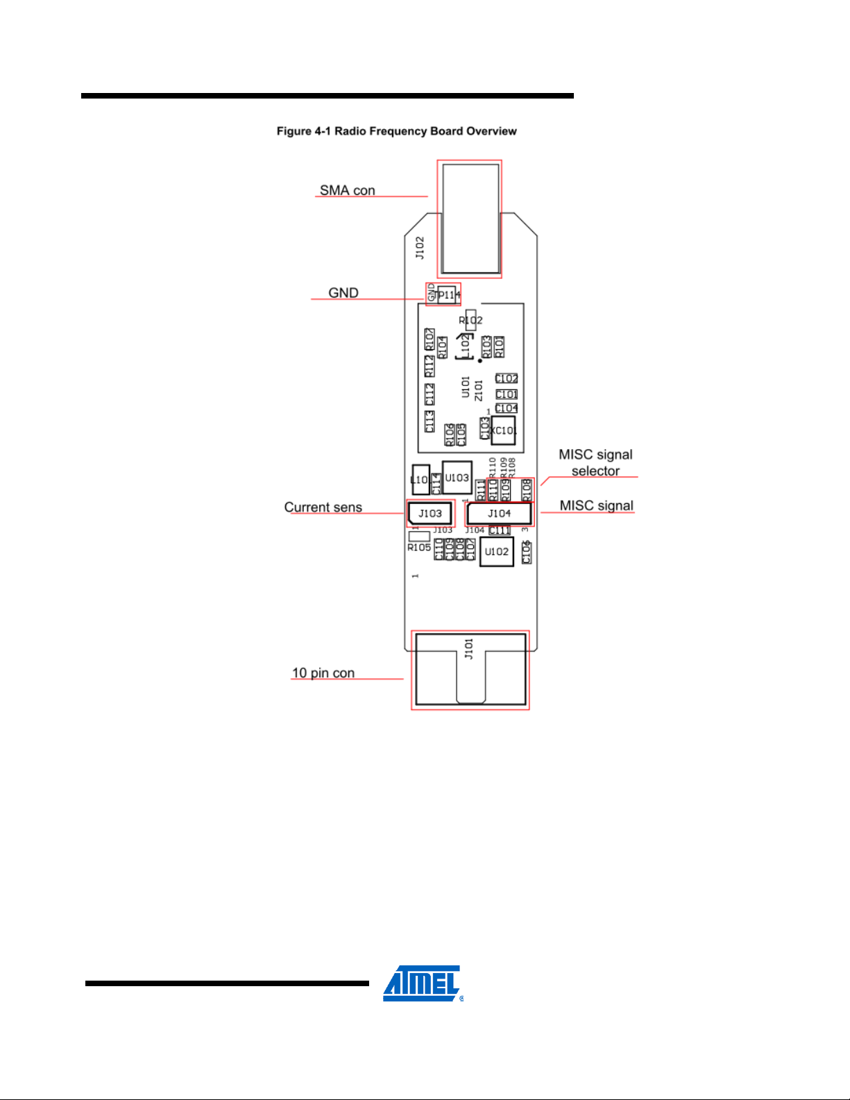
4.1 Radio Frequency Board
AT86RF232: Third generation 2.4GHz IS M band radio trans ceiver with fro nt
ends for antenna diversity and external power amplifier and encryption
accelerators.
This board and the RZ600-230, 231, 212 radio transceivers share the same
printed circuit board with slightly different component values mounted for each of
them. See Figure 4-2 for full schematics of the radio frequency board.
proper antenna for the radio transceiver.
COM ports.
terminals is the same.
4
AVRRZ600-232
NNNNN2
Page 5
AVRRZ600-232
4.2 Connectors
NNNNN
There are two main connectors on the board; one is the female SMA antenna
connector and in the opposite direction of the board is a 10-pin dual row header. See
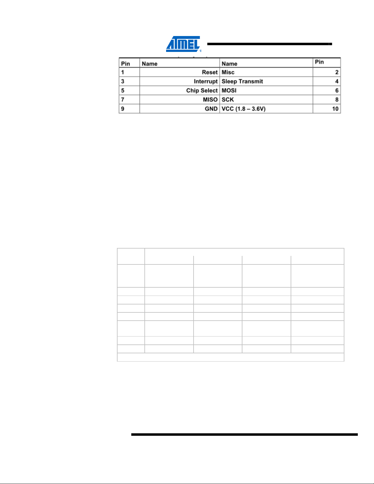
Table 4-1 for pin out of this header.
Table 4-1. Radio Frequency 10-pin header
5
Page 6
4.3 Crystal
4.4 RF Front End
There are also two single row headers on the board:
• J103 (Not mounted): Two pin header that can be soldered in to do current
measurement with an ampere meter. R105 must be unsoldered to enable this
feature.
• J104 (Not mounted): Three pin header that can be soldered in to access
the auxiliary (Miscellaneous) signals from the radio transceiver.
A high accuracy 16MHz crystal is mounted and used by the radio transceiver
for carrier frequency generation.
RZ600 radio boards shares a common layout across all the three transceivers
AT86RF212, AT86RF230, AT86RF231. For the schematic given in Figure 4-2
differences in bill of Material are as given in the Table 4-2.
Table 4-2 BoM Variants
BoM Variants
Part
U101 AT86RF232 AT86RF231 AT86RF230 AT86RF212
R101 0 ohm DNI 0 ohm DNI
R103 0 ohm DNI 0 ohm DNI
R107 DNI DNI 0 ohm DNI
R112 DNI DNI 0 ohm DNI
RF232 RF231 RF230 RF212
6
AVRRZ600-232
L102 2450FB15L0001 2450FB15L0001 2450FB15L0001 0896FB15A0100E
R102 0 ohm 0 ohm 0 ohm 100pF
R104 0 ohm 0 ohm 10k 0 ohm
*DNI -Do not Install Component
Since the output from the radio transceiver itself is a balanced signal pair, a balun is
needed to transform into a 50Ohm single ended signal fed to the SMA
connector.
The Johanson Technology recommends 2450FB15L0001 Balun which is optimized
for AT86RF232 for radio designs using this Transceiver.
NNNNN2
Page 7
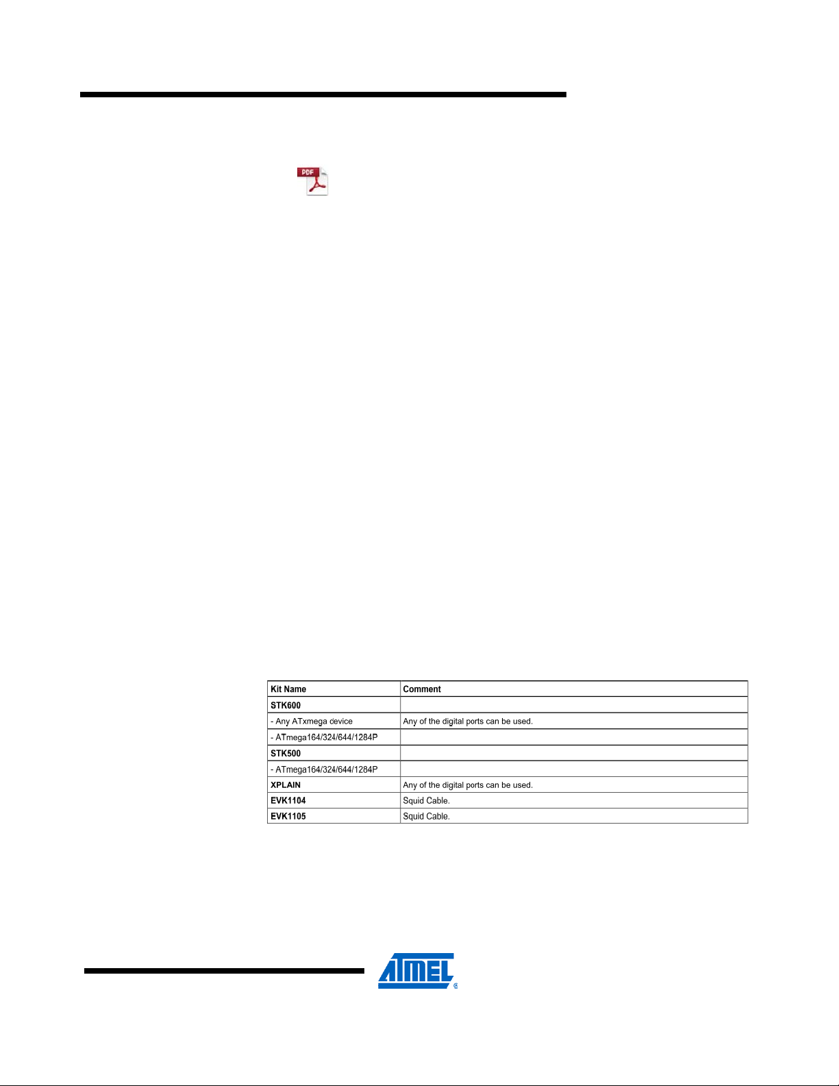
Figure 4-2 Radio Frequency Board
AVRRZ600-232
4.5 Cables
There are two different cable types available in the RZ600 kit
• Squid Cable:
• Single Wire:
5 Connecting Radio Board to Custom Board
The radio frequency boards found as part of this kit can be used stand alone as well
as in conjunction with the processor board. Table 4-1 shows the pinout of the
standardized 10-pin bus that is defined between the two unit. However, it is possible
to add the radio frequency board to any routing as long as the required signals are
available. This is possible due to the radio frequency board being able to be mounted
on the squid cable included in this kit. With this squid cable it is possible to route all
10 signals down onto a custom hardware. The reminder of this chapter shows a few
examples on how to wire these signals.
AVRRZ600-232
5.1 Default Supported Kits
5.1 Default Supported Kits
Besides from being used on the processor boards the radio frequency board can be
attached to wide range of Atmel evaluation and starter kits. The following kits
are supported directly. If you do not find your preferred kit here, please take a
look at section 5.2.
Table 5-1. Plug and Play Kits
5.2 Squid Cable
There are two squid cables (10pin male header to single wires) included in
the kit. The intended use of this special cable assembly is to plug the radio frequency
board
onto it, and connect the ten single wires to any hardware platform that does not have
the standard auxiliary connector available.
Table 5-2. Squid Cable Pinout
NNNNN
7
Page 8

6 Firmware
PIN PIN
Pin 1 (Brown): Reset Pin 2 (Red): Miscellaneous
Pin 3 (Orange): Interrupt Pin 4 (Yellow): Sleep Transmit
Pin 5 (Green): Chip Select Pin 6 (Blue): Master Out Slave In
Pin 7 (Purple): Master In Slave Out Pin 8 (Grey): SPI Clock
Pin 9 (White): Ground Pin 10 (Black): Vcc
Table 6-1. Firmware Layout
Path Comment
/Applications
/Applications/TINY_TAL_Examples Parent for Tiny TAL Example
/Applications/TINY_TAL_Examples/Wireless_UART Parent Folder for Wireless
IAR EWB Project files for
/Applications/TINY_TAL_Examples/Wireless_UART/
AT86RF232_AT32UC3A3256S_RZ600/IAR_Library
Parent Folder for kit
applications
Applications
UART application for different
RF Transceivers
AT86RF232 Transceiver.
Also contains Batch file to
download the ELF File for
AT86RF232 Transceiver.
/Applications/TINY_TAL_Examples/Wireless_UART/
AT86RF232_AT32UC3A3256S_RZ600/IAR_Library/
Release/Exe
/Applications/TINY_TAL_Examples/Wireless_UART/
Inc
/Applications/TINY_TAL_Examples/Wireless_UART/
Src
/Build
/Build/Build_RZ600_Wireless_Uart_lib Folder containing Batch File
/Build/Build_RZ600_Wireless_Uart_lib/IAR/AVR32 Batch file for building Wireless
/Doc Folder containing Reference
/Doc/Reference_Manual/TINY_TAL_AT86RF2XX_
RZ600/html
/Doc/Reference_Manual/graphics Folder containing graphics
ELF File that can be
downloaded to
AT32UC3A3256S for
AT86RF232 Transceiver.
Configuration File specific to
Wireless UART application &
ISP
Source fol der containing main
file & trampoline assembler
file.
Parent folder for Windows
Batch Files used to build the
application
for Wireless UART application
UART application developed
in IAR EWB.
Manual & Release Notes
Reference Manual for Tiny
TAL & PAL specific APIs for
RZ600 in html format
used in the reference manual
8
AVRRZ600-232
NNNNN2
Page 9

AVRRZ600-232
/Include
/PAL
/PAL/AVR32 Parent Folder for AVR32
/PAL/AVR32/AT32UC3A3256 Parent Folder for
/PAL/AVR32/AT32UC3A3256/Boards/RZ600_232 RZ600 Board specific PAL
/PAL/AVR32/AT32UC3A3256/Inc Include files for the
/PAL/AVR32/Generic/Inc Generic Include Files shared
/PAL/Inc PAL API Prototypes & PAL
/TAL
/TAL/AT86RF232/Inc Include files specific to the
/TAL/Inc Folder contains TAL API
/TINY_TAL
/TINY_TAL/AT86RF232/Inc Include files specific to the
/TINY_TAL/Inc Folder contains TINY TAL API
/UTILS
/UTILS/LINKER_SCRIPTS Linker scripts for each
/UTILS/LINKER_SCRIPTS/AT32UC3A3/256S/IAR Linker script file for IAR
/Driver
Header Fil es for application &
all layers of stack
Platform Abstraction Layer
specific Header files
AT32UC3A3256 specific
Header Files
configuration file for
AT86RF232 Transceiver
AT32UC3A3256 processor
codes
by all AVR32 devices
Types Header Files. Includes
Type definitions for multi
compiler support.
Transceiver Abstraction Layer
AT86RF232 RF Transceiver
function declarations & TAL
types header files
Tiny Transceiver Abstraction
Layer
AT86RF232 RF Transceiver
function declarations & TAL
types header files
Directory contains Linker
script files
microcontroller & compiler
compiler and
AT32UC3A3256S
microcontroller
USB CDC Driver for
AT32UC3A3256S
Microcontroller
NNNNN
9
Page 10

7 Getting Started
This chapter describes how to get started with the RZ600-232 kit and run the
demo application in the most efficient way. Read section by section sequentially and
follow the directions carefully. The quick start guide assumes that the
requirements in section 3.2 are fulfilled.
7.1 Kit Unpacking
1. Open the box and verify that all items are present as outlined in section 3.1.
2. Take two AVRRZ600-USB boards and select a pair of AVRRZ600-232 radio
transceivers to test.
3. Mount the radio frequency board onto the processor boards 10-pin
connector.
Make sure that pin 1 on both boards aligns.
4. Attach any of the auxiliary signals between the two units using the single wires.
5. Connect the RF Board to the antenna.
7.2 USB Enumeration for Windows XP
1. Connect one of the board assemblies to you PC and let it start USB enumeration
process.
2. The first time this is done, the CDC driver will have to be installed. A “Found new
hardware wizard” will pop up. Select “No, not this time” and next.
3. Select “Install from a list or specific location (Advanced). Click next. Select “Include
this location in the search:” Select the following folder in the RZ600 firmware: /Driver
4. Click finish.
5. Verify what COM port that was assigned to the USB device. This can be done from
the Control Panel under the start menu. Select Administrative Tools from the menu
and then click the Computer Management. Now click on the Computer Management
item>Device Manager and look under the Ports (COM & LPT) from the list. A new
COM port should be available
6. Repeat step 1 to 5 for the second board assembly
7.3 USB Enumeration for Windows 7
1. Connect one of the board assemblies to you PC and let it start USB enumeration
process.
2. The first time this is done, the CDC driver will have to be installed. Windows 7 does
not launch the “Found new hardware wizard” automatically.
3. Go to “Control Panel>System and Security” and click “Device Manager” under the
heading “System”.
4. Right Click on “Unknown device” under the heading “Other devices”. Select
“Update Dri ver Software”
10
AVRRZ600-232
NNNNN2
Page 11

AVRRZ600-232
5. Click “Browse my computer for driver software” and give the following folder in the
RZ600 firmware as search location: /Driver.
6. Click Next. Select “Install this driver software anyway”.
7. Verify what COM port was assigned to USB device in the Device Manager under
Ports (COM&LPT).
8. Repeat steps 1 to 7 for the second board assembly.
7.4 Run the Example Application
Any terminal application can be used to connect to the COM ports, this section shows
how to do this with HyperTerminal.
1. From the start menu select All Programs, Accessories, Communications and finally
HyperTerminal.
2. Type in a name for the connection
3. A “Connect To” dialog will appear. Make sure to select the correct COM port.
4. Press the OK button and use the setting shown in Figure 7-1. Click the OK button
again.
5. You now have a terminal window ready to use
6. Repeat steps 1 to 5 for the second board assembly.
7. Type characters in one of the terminals and verify that they are conveyed over to
the second terminal.
Figure 7-1 COM Port Settings
NNNNN
11
Page 12

7.5 Instal l Software and test
This step is only required for doing application development on the RZ600 kit.
1. Install AVR32 GNU Toolchain – see section 2.
2. Install AVR32 Studio – see section 2.
3. Install Flip 3.4.2 if bootloader programming is required. Refer section “7.5.2
Bootloader Programming using BatchISP”
4. IAR Embedded Workbench: IAR EWB workspace files given with the example
application is compatible with IAR Embedded Workbench for Atmel AVR32 3.31.1
7.6 Programming Example application with JTAGICE MKII or AVRONE
This step is only required for doing application development on the RZ600 kit.
1. Connect either a JTAG ICE mkII or AVRONE! to your computer.
2. Go through the driver installation. Let the PC select the best USB driver for
the attached debugger. The AVR USB program takes care of this in the
background.
3. Mount a 100mil to 50mil adapter to the debugger and connect the
probe to J103,JTAG header on the processor board.
4. Use AVR32 Studio or IAR Embedded Workbench to develop and debug
programs.
12
AVRRZ600-232
NNNNN2
Page 13

7.7 Bootloader Programming using Batch ISP
AT32UC3A3256S on RZ600 Processor boards are shipped with preprogrammed
bootloader along with the example application using AT86RF231 transceiver. The
following sequence is suggested for loading AT32UC3A3256S wit h any other output
elf file. Refer the “Table 6-1 Firmware layout” to find the path for the elf release file of
example application for all the transceivers.
BatchISP programming is supported on AVR32 target by the Trampoline section
placed at the reset vector (80000000h). For more details about Trampoline section for
AVR32, refer BatchISP application note 7745C,
http://www.atmel.com/dyn/resources/prod_documents/doc7745.pdf
1. Short the pin 1(GND) & pin 2(USART TX) of J105, 3-pin UART Header
before connecting the RZ600 USB Stick to the PC.
2. Connect the device to the USB port of computer. This will activate the ISP
and open a New Hardware Installation Window the first time this is done.
3. Choose not to connect to Windows Update for this installation and click
‘Next’.
AVRRZ600-232
NNNNN
4. On the next screen, select “Install from a list or specific location (Advanced)”
and click ‘Next ’
13
Page 14

5. Then request to search in the usb folder of the FLIP installation directory and
Click Next.
14
AVRRZ600-232
NNNNN2
Page 15

6. After the completion of driver installation click Finish.
AVRRZ600-232
7. Next navigate to the location where IAR EWB project files for the selected
transceiver are located in the RZ600 firmware. Refer “Table 6-1 Firmware
layout” for the location.
8. Execute the Batch File to load the firmware into the processor board and
launch the appl i c ation using Bat c hI S P .
9. Repeat the above steps for the second processor board also. Device driver
need not be installed the second time.
10. Follow the steps given in Section 7.3 to run the example application.
NNNNN
15
Page 16

7.8 Programming the Bootloader
This steps needs to be followed only if the preprogrammed bootloader on RZ600
Processor board is erased.
1. Connect a JTAG ICE mkII to your computer
2. Go through the driver installation. Let the PC select the best USB driver for
3. Solder the 50 mil 10-pin connector to one of the processor board.
4. Mount a 100mil to 50mil adapter to the debugger and connect the probe to
5. Use AVR32 Studio to program the bootloader as explained in the following
6. In the AVR32 Studio Targets pane select JTAG ICE mkII and press Enter to
7. In the Properties View select the Device as UC3A3256S and board as
the attached debugger. The AVR USB program takes care of this in the
background.
the freshly soldered connector. Be sure to use the correct orientation of
10 pin header when connecting the JTAG ICE mkII to the target application
PCB
steps.
open the Properties View.
Unspecified.
16
AVRRZ600-232
8. Select “Program Bootloader” in the Target Context Menu.
NNNNN2
Page 17

AVRRZ600-232
NNNNN
9. In the AT32UC3 Bootloader Wizard select Type: USB DFU & Version
1.0.3.Pres s Next Button.
10. Set up the User page configuration Word as 0x929E0454 with
ISP_IO_COND_PIN=4 & Fuse bit Configuration value as 0xFFF7FFFF which
is the default value.
17
Page 18

11. Press the Finish Button.
8 Appendix - FCC Statements
8.1 Equipment Usage
This equipment is for use by developers for evaluation purposes only and must not be
incorporated into any other device or system.
8.2 Compliance Statement – Part 15.19
These devices comply with Part 15 of the FCC Rules. Operation is subject to
the following two conditions:
1. These devices may not cause harmful interference, and
2. These devices must accept any interference received, including interference
that may cause undesired operation.
18
AVRRZ600-232
NNNNN2
Page 19

8.3 Warning – Part 15.21
Changes or modifications not expressly approved by Atmel Norway could void
the user’s authority to operate the equipment.
8.4 Compliance Statement – Part 15.105(b)
This equipment has been tested and found to comply with the limits for a
Class B digital device, pursuant to Part 15 of the FCC Rules. These limits are
designed to provide reasonable protection against harmful interference in a
residential installation.
This equipment generates uses and can radiate radio frequency energy and, if
not installed and used in accordance with the instructions, may cause
harmful interference to radio communications. However, there is no
guarantee that interference will not occur in a particular installation. If this
equipment does cause harmful interference to radio or television reception,
which can be determined by turning the equipment off and on, the user is
encouraged to try to correct the interference by one or more of the following
measures:
• Reorient or relocate the receiving antenna.
• Increase the separation between the equipment and receiver.
• Connect the equipment into an outlet on a circuit different from that to which the
receiver is connected.
• Consult the dealer or an experienced radio engineer for help.
AVRRZ600-232
8.5 FCC ID
PCBA Number : A09-1078
Transceiver :AT86RF232
FCC ID :VW4A091078
This device is only allowed to be connected to MCU units made by ATMEL and
specifically designated for use with this Module FCC ID VW4A091078
The use of all other host systems need to be re-certified by the FCC (through a new
certification or a Class 2 Permissive Change procedure)
9 Appendix – European Union – ETSI Statements
The AVRRZ600-232 kit has been certified for use in European Union countries. If this
product is incorporated into a product, the manufacturer must ensure compliance of
the final product to the European harmonized EMC and low-voltage/safety standards.
A Declaration of Conformity must be issued for each of these standards and kept on
file as described in Annex II of the R&TTE Directive.
Furthermore, the manufacturer must maintain a copy of the modules' docum entation
and ensure the final product does not exceed the specified power ratings, antenna
specifications, and/or installation requirements as specified in the user manual. If any
of these specifications are exceeded in the final product, a submission must be made
to a notified body for compliance testing to all required standards.
IMPORTANT: The 'CE' marking must be affixed to a visible location on the OEM
product.
NNNNN
19
Page 20

The CE marking must have a height of at least 5mm except where this is not possible
on account of the nature of the apparatus.
The CE marking must be affixed visibly, legibly, and indelibly.
More detailed information about CE marking requirements you can find at
"DIRECTIVE 1999/5/EC OF THE EUROPEAN PARLIAMENT
AND OF THE COUNCIL" on 9 March 1999 at section 12.
20
AVRRZ600-232
NNNNN2
Page 21

Atmel Corporation
2325 Orchard Parkway
San Jose, CA 95131
USA
Tel: (+1)(408) 441-0311
Fax: (+1)(408) 487-2600
www.atmel.com
© 2011 Atmel Corporation. All rights reserved. / Rev.: CORP072610
Atmel®, Atmel logo and combinations thereof, AVR®, AVR® logo, AVR Studio®, megaAVR®, QTouch®, DataFlash®, and others are
registered trademarks of Atmel Corporation or its subsidiaries. Other terms and product names may be trademarks of others.
Disclaimer: The information in this document is provided in connection with Atmel products. No license, express or implied, by estoppel or otherwise, to
any intellectual property right is granted by this document or in connection with the sale of Atmel products. EXCEPT AS SET FORTH IN THE ATMEL
TERMS AND CONDITIONS OF SALES LOCATED ON THE ATMEL WEBSITE, ATMEL ASSUMES NO LIABILITY WHATSOEVER AND DISCLAIMS
ANY EXPRESS, IMPLIED OR STATUTORY WARRANTY RELATING TO ITS PRODUCTS INCLUDING, BUT NOT LIMITED TO, THE IMPLIED
WARRANTY OF MERCHANTABILITY, FITNESS FOR A PARTICULAR PURPOSE, OR NON-INFRINGEMENT. IN NO EVENT SHALL ATMEL BE
LIABLE FOR ANY DIRECT, INDIRECT, CONSEQUENTIAL, PUNITIVE, SPECIAL OR INCIDENTAL DAMAGES (INCLUDING, WITHOUT LIMITATION,
DAMAGES FOR LOSS AND PROFITS, BUSINESS INTERRUPTION, OR LOSS OF INFORMATION) ARISING OUT OF THE USE OR INABILITY TO
USE THIS DOCUMENT, EVEN IF ATMEL HAS BEEN ADVISED OF THE POSSIBILITY OF SUCH DAMAGES. Atmel makes no representations or
warranties with respect to the accuracy or completeness of the contents of this document and reserves the right to make changes to specifications and
product descriptions at any time without notice. Atmel does not make any commitment to update the information contained herein. Unless specifically
provided otherwise, Atmel products are not suitable for, and shall not be used in, automotive applications. Atmel products are not intended, authorized, or
warranted for use as components in applications intended to support or sustain life.
Atmel Asia Limited
Unit 01-5 & 16, 19F
BEA Tower, Milennium City 5
418 Kwun Tong Road
Kwun Tong, Kowloon
HONG KONG
Tel: (+852) 2245-6100
Fax: (+852) 2722-1369
Atmel Munich GmbH
Business Campus
Parkring 4
D-85748 Garching b. Munich
GERMANY
Tel: (+49) 89-31970-0
Fax: (+49) 89-3194621
Atmel Japan
9F, Tonetsu Shinkawa Bldg.
1-24-8 Shinkawa
Chou-ku, Tokyo 104-0033
JAPAN
Tel: (+81) 3523-3551
Fax: (+81) 3523-7581
NNNNN
 Loading...