

Page 1
RCB Certification Firmware Manual
Features
• User Manual for RCB Certification Firmware
1 Introduction
The manual describes the usage of RCB (DUT) firmware for certification purposes.
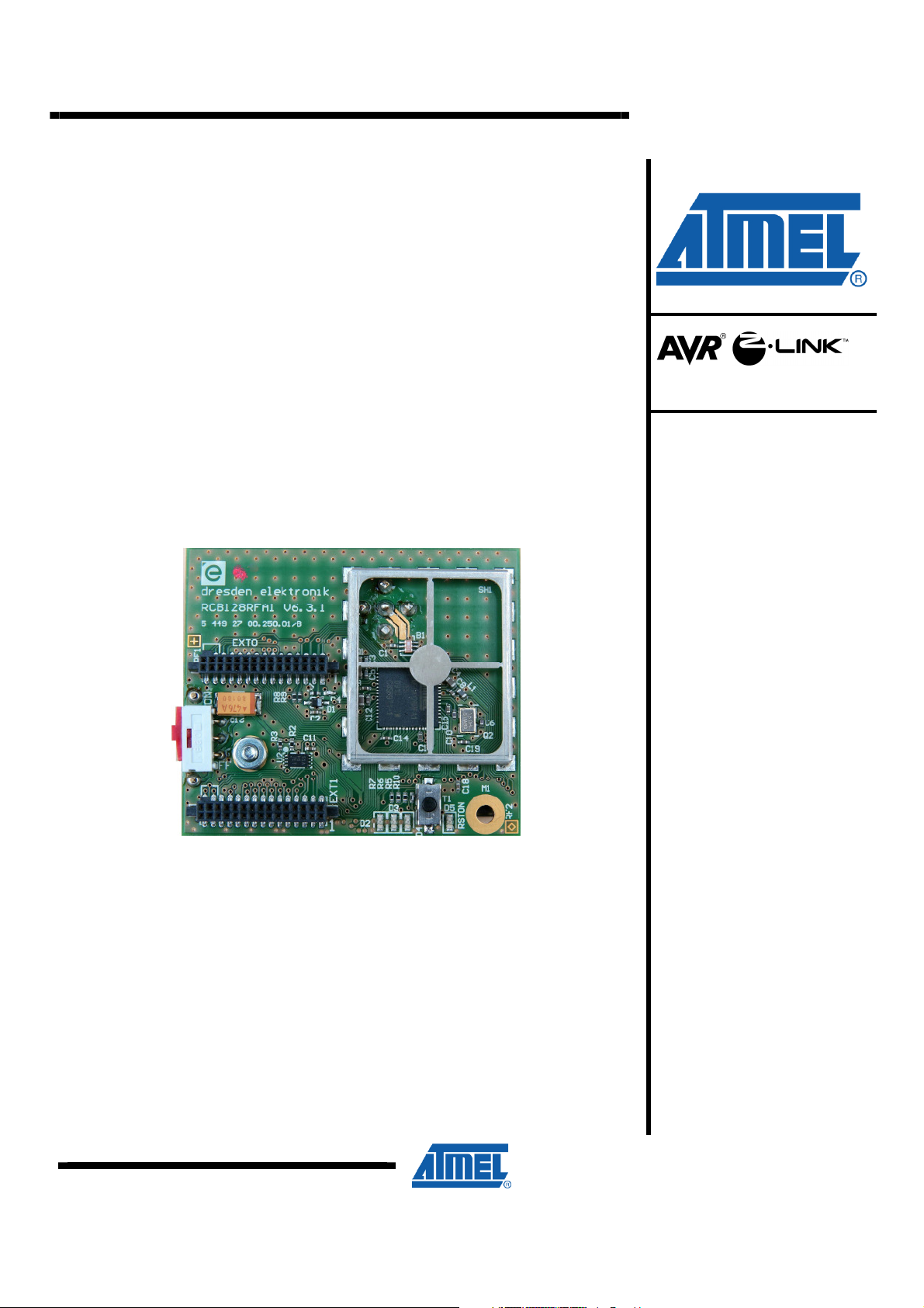
Figure 1-1 as an example shows one target board demonstrating the 8 bit AVR
microcontroller with integrated low power 2.4 GHz transceiver [1].
Figure 1-1. RCB128RFA1 – Single-Chip Radio Controller Board
RCB Certification
Firmware Manual
Other DUTs may look different with a slightly different user interface, for details
refer to section 2.
Rev. 0001B-AVR-10/09
Page 2
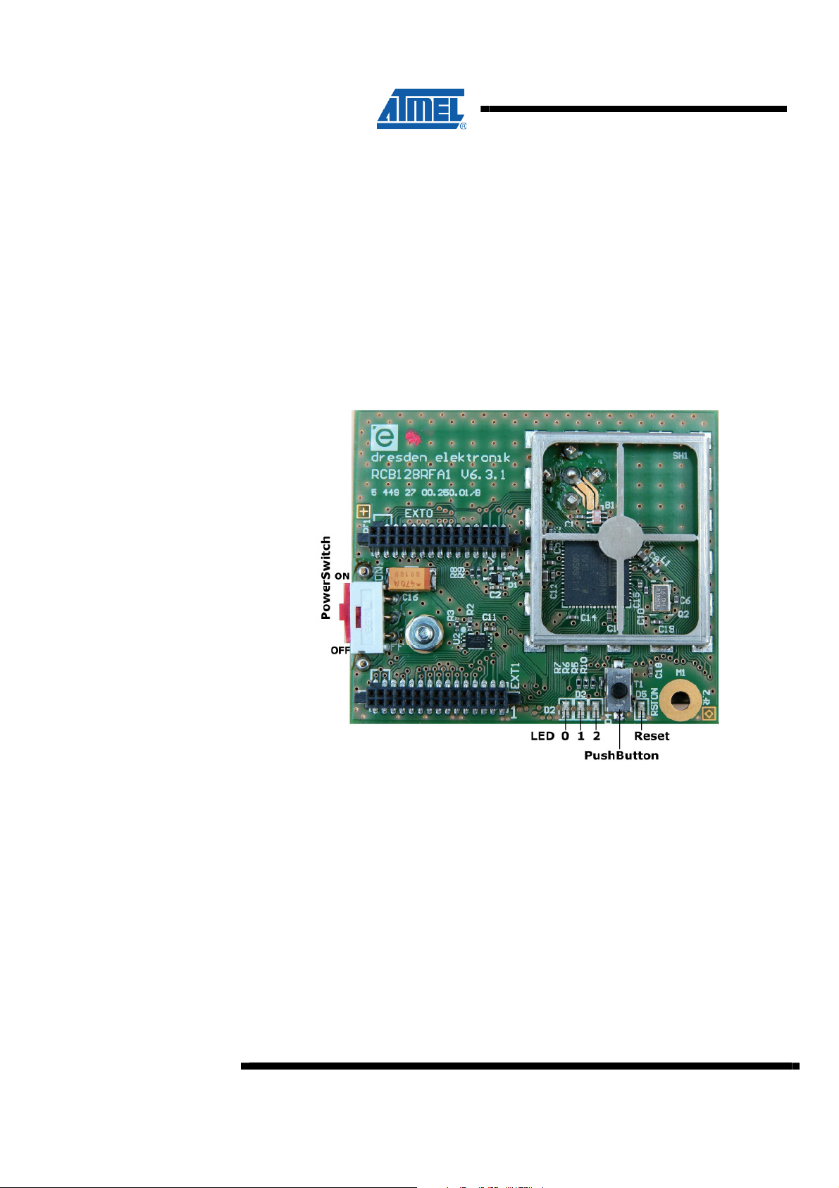
2.1 RCB128RFA1 v6.3.1
2 Hardware Description
The RCB features the following user interface:
• (3) STATUS LED’s (LED_0 … LED_2)
• (1) RESET LED (LED_R)
• (1) Push Button (Button)
• (1) Power Switch (Sw)
Figure 2-1. RCB128RFA1 v6.3.1 – User Interface
2
Main components:
• 8 bit AVR microcontroller with integrated low power 2.4 GHz transceiver [1]
• AT25010A, EEPROM
• Antenna, Mobile Mark PSTG0-2400HS
Figure 1-1 shows the RCB without shielding cover in an active state, the
microcontroller part is running and the radio transceiver part is in TRX_OFF state
(IDLE / Standby). For details refer to the next sections. The RCB is manufactured,
tested and shipped with shielding cover attached to the frame.
AVR0000
0001B-AVR-10/09
Page 3
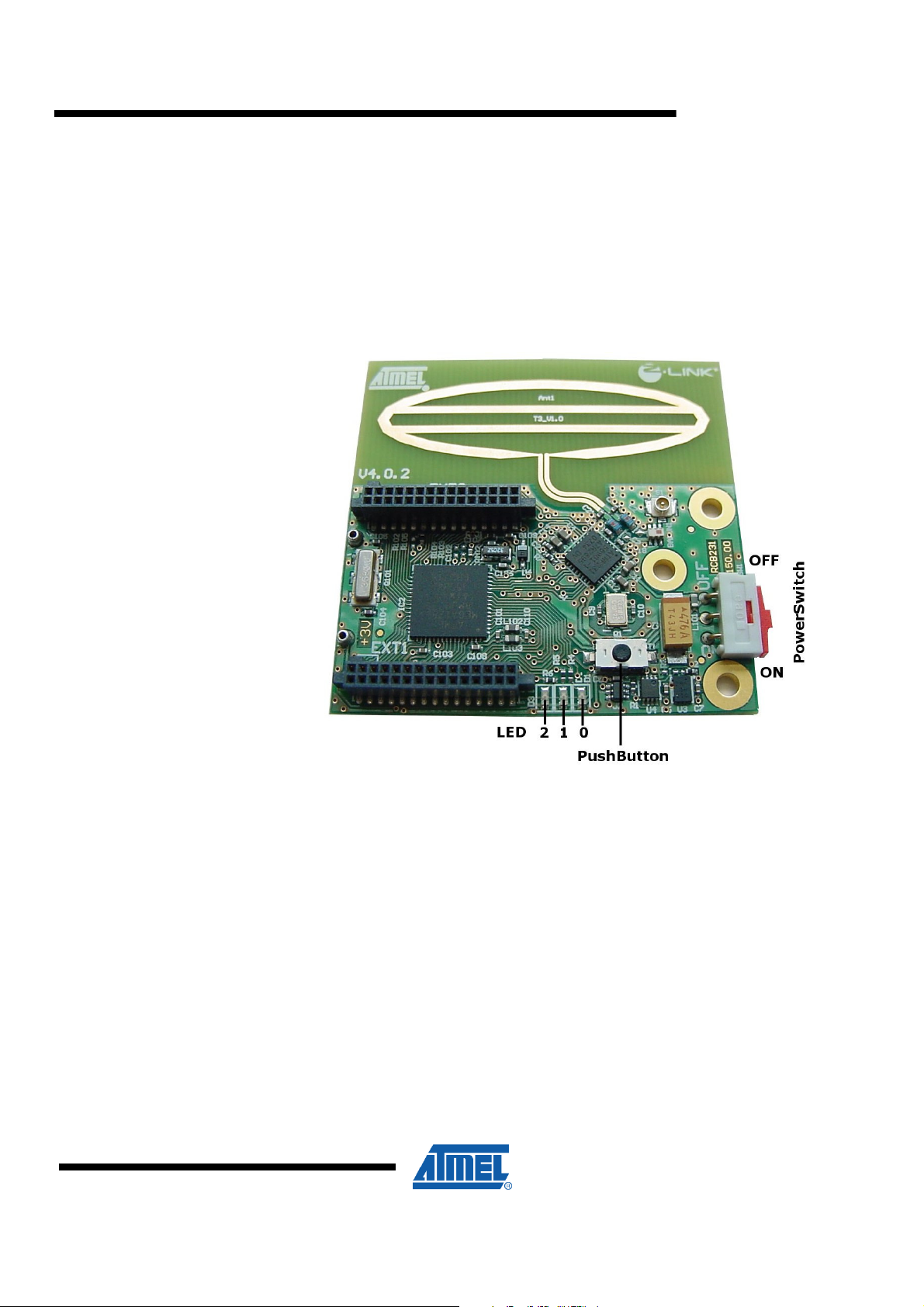
2.2 RCB231 v4.0.2
AVR0000
The RCB features the following user interface:
• (3) STATUS LED’s (LED_0 … LED_2)
• (1) Push Button (Button)
• (1) Power Switch (Sw)
Figure 2-2. RCB231 v4.0.2 – User Interface
0001B-AVR-10/09
Main components:
• AT86RF231, 2.4 GHz low power radio transceiver [2]
• ATmega1281, 8 bit AVR microcontroller
• AT25010A, EEPROM
• Antenna, on board or antenna connector
The picture shows the RCB in an active state, the microcontroller part is running and
the radio transceiver part is in TRX_OFF state (IDLE / Standby). For details refer to
the next sections. Note the different order or weighting of the LED’s compared to the
RCB shown in 2.1.
3
Page 4
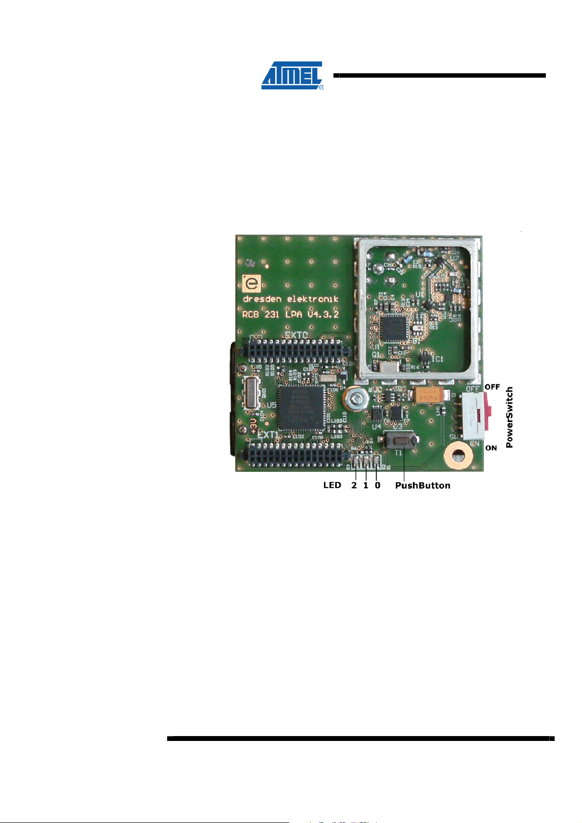
2.3 RCB231LPA v4.3.2
The RCB features the following user interface:
• (3) STATUS LED’s (LED_0 … LED_2)
• (1) Push Button (Button)
• (1) Power Switch (Sw)
Figure 2-3. RCB231LPA v4.3.2 – User Interface
4
Main components:
• AT86RF231, 2.4 GHz low power radio transceiver [2]
• uPG2314T5N, Power Amplifier
• ATmega1281, 8 bit AVR microcontroller
• AT25010A, EEPROM
• Antenna, Mobile Mark PSTG0-2400HS
The picture shows the RCB in OFF state. Note the different order or weighting of the
LED’s compared to the RCB shown in 2.1.
Figure 2-3 shows the RCB for illustration without shielding cover. However, the board
is manufactured, tested and shipped with shielding attached to the frame.
AVR0000
0001B-AVR-10/09
Page 5

2.4 RCB212SMA v5.3.2
AVR0000
To be defined, no firmware support yet.
0001B-AVR-10/09
5
Page 6

3 Firmware Description
3.1 Prerequisites
Before power-on the DUT by moving (Sw) to (ON) position, ensure the DUT is
equipped with two AAA batteries. These batteries are to be placed at the back side of
the DUT in the battery holder. Pay attention to the correct polarity of the batteries.
3.2 Power-On and Configuration
There are two possibilities to power-on the DUT:
1. Without DUT configuration update,
2. Configuration mode (press (Button) during power-on).
The next sections describe different ways to power-on a DUT in detail.
3.2.1 Without DUT Configuration Update
The first choice is the standard selection to power-on the DUT.
To select operation without radio transceiver configuration update, power-on the DUT
by switching (Sw) to (ON) position. Do not press the (Button).
There are two possible system configurations:
3.2.2 Configuration Mode
3.2.2.1 Factory Reset
• The very first power-on cycle (factory reset) enables operation at maximum TX
output power and standard PSDU data rate. The DUT starts at test mode state “0”,
refer to section 3.3.
• All other power-on cycles remember the last radio transceiver configuration and
test mode selection before last power-off cycle.
If available, the LED indicating the reset state (LED_R) is on for a short time. Once
this LED is off again, the microcontroller is waiting for a new (Button) command.
Power-on the DUT in configuration mode allows either:
• Reset to factory configuration, and, if required
• Selection of TX output power and/or PSDU data rate, see references [1…2].
To do this, press and hold the (Button) before power-up the DUT. Once the DUT is
powered on, the three state LED’s (LED_0 … LED_2) are switched on. Further
handling of the (Button) determines the next configuration options.
If the (Button) is pressed during power-on and immediately released afterwards,
factory reset configuration is loaded.
If TX output power has to be switched to the minimum value do not release the
(Button) within two seconds, for details refer to 3.2.2.2.
6
AVR0000
0001B-AVR-10/09
Page 7

If no further (Button) activity is recognized, all three state LED’s are switched off 5 sec
later. Continue to select the test mode as described in section 3.3.
3.2.2.2 Transmitter Output Power Selection
If the (Button) is not released for about two seconds after power-on, the TX output
power is set to the minimum possible value. This is indicated by switching off the
three state LED’s (LED_0 … LED_2), and immediately after switching on state LED
(LED_2). Now the (Button) has to be released to continue with PSDU data rate
selection, or wait to leave the radio transceiver configuration menu 5 sec later.
PSDU Data Rate Selection
Release the (Button) either immediately or after TX output power selection, to enable
the PSDU rate selection. This is possible independently on a previous TX output
configuration. Each new (Button) press toggles the status LED’s similar to a binary
counter between 1 through 4. Note, a new (Button) press event to select the PSDU
data rate has to be performed within 5 sec after power-on or TX output power
selection. Otherwise the configuration menu is left towards the Test Mode Selection,
see section 3.3.
The PSDU data rate is coded as follow:
Table 3-1. Configuration Settings for 2.4 GHz Radio Transceiver
State LED_0 LED_1 LED_2 Description
0 ON ON ON Factory reset value
1 ON off off PSDU data rate = 250 kb/s
2 off ON off PSDU data rate = 500 kb/s
3 ON ON off PSDU data rate = 1000 kb/s
4 off off ON PSDU data rate = 2000 kb/s
other other configurations are not available yet
AVR0000
PSDU data rate = 250 kb/s
0001B-AVR-10/09
Once state 4 is reached, a new (Button) press starts at state 1.
If, after power-on, perhaps TX output power selection and the first (Button) release,
the (Button) is not pressed, as well as after each new (Button) press event to toggle
the PSDU data rate, a 5 sec timer is started to automatically leave the radio
transceiver configuration. Each new (Button) press resets the timer.
Leaving the radio transceiver configuration is done automatically after about 5 sec
and indicated by switching all state LED’s off.
Note, the configuration menu is only accessible after power-on. Each new TX output
power or PSDU data rate configuration requires a power cycle of the DUT.
7
Page 8

3.3 Test Mode Selection
After power-on, and optionally DUT configuration, the DUT is waiting for user input, in
detail a (Button) press event. As long as no (Button) press occurs, the system
remains in the state after power-on, see table below.
Each new (Button) press event switches to the next state, for example after the initial
state 0 (TRX_OFF) a (Button) press selects state 1, the radio transceiver starts to
transmit a continuous wave carrier at channel 11. The TX output power used is
according to the initial configuration.
Table 3-2. Test Mode Selection Table
State LED
0 1 2
0 n/a TRX_OFF
1 B
2 B 18
3 B 26
4 B 11 1 TX yes
5 B 18 1 TX yes
6 B 26 1 TX yes
7 B 11 0.5 TX yes
8 B 18 0.5 TX yes
9 B 26 0.5 TX yes
10 B 11 0.2 RX n/a n/a
11 B 18 0.2 RX n/a n/a
12 B 26 0.2 RX n/a n/a
(1)
(2)
11
Channel Blink
Period
[sec]
(3)
2 TX no CW
(3)
2 TX no CW
(3)
2 TX no CW
Notes: (1) Note the individual LED order for each RCB type.
RX/TX Modulation Burst Comment
(4)
CW
(4)
CW
(4)
CW
(4)
burst 100 ms
(4)
burst 100 ms
(4)
burst 100 ms
8
AVR0000
(2) B indicates LED is blinking, all other LED’s are off
(3) Due to the radio transceiver architecture the
unmodulated, CW TX RF frequency is at
f
TX,CW,noMod
modulation bandwidth of a modulated TX output
signal.
(4) These states using the PSDU data rate setting as
configured after power-on, refer to 3.2.
= f
– 0.5 MHz. But still within the
channel
The selected channel is indicated by the corresponding LED, whereas the blinking
period indicates the operating mode.
A new (Button) press selects the next state. Once state 12 is reached, the next
(Button) press switches to state 0, and therefore sets the radio transceiver part back
into TRX_OFF (IDLE / Standby) state.
It is not possible to change the PSDU data rate within this operating mode. Doing this
requires a DUT power cycle as described in section 3.2.
0001B-AVR-10/09
Page 9

3.4 Error Handling
AVR0000
In test scenarios where external interferers or events are applied to check the
robustness of the DUT, the device may not be able to continue with normal operation.
Normal operation according to 3.3 is always indicated with one out of three LED’s
blinking, whereas an error condition is visualized by all three state LED’s (LED_0 …
LED_2) on.
If a malfunction is indicated and the DUT is not damaged, it returns to normal
operation after two seconds. The same holds for unexpected resets of the whole
system, for instance during an ESD stress test. Such an event may cause an internal
reset and the DUT immediately continues with normal operation according to the
mode selected before.
Furthermore, any behavior of the state LED’s different to 3.3 indicates a malfunction
of either the microcontroller or radio transceiver part.
0001B-AVR-10/09
9
Page 10

4 Abbreviations
DUT - Device Under Test
LED - Light Emitting Diode
PHY - Physical Layer
PSDU - PHY Service Data Unit
RCB - Radio Controller Board
RX - Receiver
TX - Transmitter
10
AVR0000
0001B-AVR-10/09
Page 11

AVR0000
5 EVALUATION BOARD/KIT IMPORTANT NOTICE
This evaluation board/kit is intended for use for FURTHER ENGINEERING,
DEVELOPMENT, DEMONSTRATION, OR EVALUATION PURPOSES ONLY. It is
not a finished product and may not (yet) comply with some or any technical or legal
requirements that are applicable to finished products, including, without limitation,
directives regarding electromagnetic compatibility, recycling (WEEE), FCC, CE or UL
(except as may be otherwise noted on the board/kit). Atmel supplied this board/kit
“AS IS,” without any warranties, with all faults, at the buyer’s and further users’ sole
risk. The user assumes all responsibility and liability for proper and safe handling of
the goods. Further, the user indemnifies Atmel from all claims arising from the
handling or use of the goods. Due to the open construction of the product, it is the
user’s responsibility to take any and all appropriate precautions with regard to
electrostatic discharge and any other technical or legal concerns.
EXCEPT TO THE EXTENT OF THE INDEMNITY SET FORTH ABOVE, NEITHER
USER NOR ATMEL SHALL BE LIABLE TO EACH OTHER FOR ANY INDIRECT,
SPECIAL, INCIDENTAL, OR CONSEQUENTIAL DAMAGES.
No license is granted under any patent right or other intellectual property right of
Atmel covering or relating to any machine, process, or combination in which such
Atmel products or services might be or are used.
Mailing Address: Atmel Corporation, 2325 Orchard Parkway, San Jose, CA 95131
Copyright © 2009, Atmel Corporation
0001B-AVR-10/09
11
Page 12

References
History
[1] ATmega128RFA1; 8 bit AVR microcontroller with Low Power 2.4 GHz
transceiver for ZigBee and IEEE802.15.4; Datasheet; Rev. AVR-15/June/2009;
Atmel Corporation
[2] AT86RF231; Low Power, 2.4 GHz Transceiver for ZigBee, IEEE 802.15.4,
6LoWPAN, RF4CE, SP100, WirelessHART and ISM Applications; Datasheet;
Rev. 8111C-MCU Wireless-10/09; Atmel Corporation
[3] AT86RF212; Low Power 700/800/900 MHz Transceiver for IEEE 802.15.4,
P802.15.4c Draft Amendment, Zigbee, 6LoWPAN, and ISM Applications;
Datasheet; Rev. 8186B-MCU Wireless-02/09; Atmel Corporation
[4] ATmega1281/V; 8-bit Microcontroller with 128K Bytes In-System Programmable
Flash; Datasheet; Rev. 2549L–AVR–08/07; Atmel Corporation
Rev. 0001A-AVR-10/09
• Initial Release
Rev. 0001B-AVR-10/09
• Firmware modification
o Recovery of DUT operation mode after power-cycle
o Possibility to reset to factory settings
o Error handling during DUT stress events (e.g. ESD)
12
AVR0000
0001B-AVR-10/09
Page 13

Disclaimer
Headquarters International
Atmel Corporation
2325 Orchard Parkway
San Jose, CA 95131
USA
Tel: 1(408) 441-0311
Fax: 1(408) 487-2600
Atmel Asia
Unit 1-5 & 16, 19/F
BEA Tower, Millennium City 5
418 Kwun Tong Road
Kwun Tong, Kowloon
Hong Kong
Tel: (852) 2245-6100
Fax: (852) 2722-1369
Atmel Europe
Le Krebs
8, Rue Jean-Pierre Timbaud
BP 309
78054 Saint-Quentin-enYvelines Cedex
France
Tel: (33) 1-30-60-70-00
Fax: (33) 1-30-60-71-11
Atmel Japan
9F, Tonetsu Shinkawa Bldg.
1-24-8 Shinkawa
Chuo-ku, Tokyo 104-0033
Japan
Tel: (81) 3-3523-3551
Fax: (81) 3-3523-7581
Product Contact
Web Site
www.atmel.com
Disclaimer: The information in this document is provided in connection with Atmel products. No license, express or implied, by estoppel or otherwise, to any
intellectual property right is granted by this document or in connection with the sale of Atmel products. EXCEPT AS SET FORTH IN ATMEL’S TERMS AND
CONDITIONS OF SALE LOCATED ON ATMEL’S WEB SITE, ATMEL ASSUMES NO LIABILITY WHATSOEVER AND DISCLAIMS ANY EXPRESS, IMPLIED
OR STATUTORY WARRANTY RELATING TO ITS PRODUCTS INCLUDING, BUT NOT LIMITED TO, THE IMPLIED WARRANTY OF MERCHANTABILITY,
FITNESS FOR A PARTICULAR PURPOSE, OR NON-INFRINGEMENT. IN NO EVENT SHALL ATMEL BE LIABLE FOR ANY DIRECT, INDIRECT,
CONSEQUENTIAL, PUNITIVE, SPECIAL OR INCIDENTAL DAMAGES (INCLUDING, WITHOUT LIMITATION, DAMAGES FOR LOSS OF PROFITS,
BUSINESS INTERRUPTION, OR LOSS OF INFORMATION) ARISING OUT OF THE USE OR INABILITY TO USE THIS DOCUMENT, EVEN IF ATMEL HAS
BEEN ADVISED OF THE POSSIBILITY OF SUCH DAMAGES. Atmel makes no representations or warranties with respect to the accuracy or completeness of the
contents of this document and reserves the right to make changes to specifications and product descriptions at any time without notice. Atmel does not make any
commitment to update the information contained herein. Unless specifically provided otherwise, Atmel products are not suitable for, and shall not be used in,
automotive applications. Atmel’s products are not intended, authorized, or warranted for use as components in applications intended to support or sustain life.
© 2009 Atmel Corporation. All rights reserved. Atmel®, logo and combinations thereof, AVR®, Z-LINK® logo and others, are registered
trademarks or trademarks of Atmel Corporation or its subsidiaries. Other terms and product names may be trademarks of others..
Literature Request
www.atmel.com/literature
Technical Support
avr@atmel.com
Sales Contact
www.atmel.com/contacts
0001B-AVR-10/09
 Loading...