

Page 1

3DTouchPad
User’s Guide
2014 Microchip Technology Inc. DS40001763A
Page 2

Note the following details of the code protection feature on Microchip devices:
YSTEM
CERTIFIED BY DNV
== ISO/TS 16949 ==
• Microchip products meet the specification contained in their particular Microchip Data Sheet.
• Microchip believes that its family of products is one of the most secure families of its kind on the market today, when used in the
intended manner and under normal conditions.
• There are dishonest and possibly illegal methods used to breach the code protection feature. All of these methods, to our
knowledge, require using the Microchip products in a manner outside the operating specifications contained in Microchip’s Data
Sheets. Most likely, the person doing so is engaged in theft of intellectual property.
• Microchip is willing to work with the customer who is concerned about the integrity of their code.
• Neither Microchip nor any other semiconductor manufacturer can guarantee the security of their code. Code protection does not
mean that we are guaranteeing the product as “unbreakable.”
Code protection is constantly evolving. We at Microchip are committed to continuously improving the code protection features of our
products. Attempts to break Microchip’s code protection feature may be a violation of the Digital Millennium Copyright Act. If such acts
allow unauthorized access to your software or other copyrighted work, you may have a right to sue for relief under that Act.
Information contained in this publication regarding device
applications and t he lik e is provided only for your convenience
and may be su perseded by upda t es . It is y our responsibility to
ensure that your application meets with your specifications.
MICROCHIP MAKES NO REPRESENTATIONS OR
WARRANTIES OF ANY KIND WHETHER EXPRESS OR
IMPLIED, WRITTEN OR ORAL, STATUTORY OR
OTHERWISE, RELATED TO THE INFORMATION,
INCLUDING BUT NOT LIMITED TO ITS CONDITION,
QUALITY, PERFORMANCE, MERCHANTABILITY OR
FITNESS FOR PURPOSE. Microchip disclaims all liability
arising from this information and its use. Use of Microchip
devices in life supp ort and/or safety ap plications is entir ely at
the buyer’s risk, and the buyer agrees to defend, indemnify and
hold harmless M icrochip from any and all dama ges, claims,
suits, or expenses re sulting from such use. No licens es are
conveyed, implicitly or otherwise, under any Microchip
intellectual property rights.
Trademarks
The Microchip name and logo, the Microchip logo, dsPIC,
FlashFlex, flexPWR, JukeBlox, K
LANCheck, MediaLB, MOST, MOST logo, MPLAB,
OptoLyzer , PIC, PICSTART, PIC
SST, SST Logo, SuperFlash and UNI/O are registered
trademarks of Microchip Technology Incorporated in the
U.S.A. and other countries.
The Embedded Control Solutions Company and mTouch are
registered trademarks of Microchip Technology Incorporated
in the U.S.A.
Analog-for-the-Digital Age, BodyCom, chipKIT, chipKIT logo,
CodeGuard, dsPICDEM, dsPICDEM.net, ECAN, In-Circuit
Serial Programming, ICSP , I nter-Chip Connectivity, KleerNet,
KleerNet logo, MiWi, MPASM, MPF, MPLAB Certified logo,
MPLIB, MPLINK, MultiTRAK, NetDetach, Omniscient Code
Generation, PICDEM, PICDEM.net, PICkit, PICtail,
RightTouch logo, REAL ICE, SQI, Serial Quad I/O, Total
Endurance, TSHARC, USBCheck, VariSense, ViewSpan,
WiperLock, Wireless DNA, and ZENA are trademarks of
Microchip Technology Incorporated in the U.S.A. and other
countries.
SQTP is a service mark of Microchip T echnology Incorporated
in the U.S.A.
Silicon Storage Technology is a registered trademark of
Microchip Technology Inc. in other countries.
GestIC is a registered trademarks of Microchip Technology
Germany II GmbH & Co. KG, a subsidiary of Microchip
Technology Inc., in other countries.
All other trademarks mentioned herein are property of their
respective companies.
© 2014, Microchip Technology Incorporated, Printed in the
U.S.A., All Rights Reserved.
ISBN: 978-1-63276-524-6
EELOQ, KEELOQ logo, Kleer,
32
logo, RightT ouch, S pyNIC,
QUALITY MANAGEMENT S
DS40001763A-page 2 2014 Microchip Technology Inc.
Microchip received ISO/TS-16949:2009 certification for its worldwide
headquarters, design and wafer fabrication facilities in Chandler and
Tempe, Arizona; Gresham, Oregon and design centers in California
and India. The Company’s quality system processes and procedures
are for its PIC
devices, Serial EEPROMs, microperipherals, nonvolatile memory and
analog products. In addition, Microchip’s quality system for the design
and manufacture of development systems is ISO 9001:2000 certified.
®
MCUs and dsPIC® DSCs, KEELOQ
®
code hopping
Page 3

Object of Declaration: 3DTouchPad
2014 Microchip Technology Inc. DS40001763A-page 3
Page 4

3DTouchPad USER’S GUIDE
Table of Contents
Preface ...........................................................................................................................5
Chapter 1. 3DTouchPad Overview
1.1 Introduction ...................................................................................................10
Chapter 2. Package Content and Installation
2.1 Getting Sta rted ............................................................................................. 11
Chapter 3. Feature Description
Chapter 4. Hardware
4.1 Introduction ...................................................................................................13
4.2 Hardware S e tu p ............. ................ .............................................................. 13
4.3 3D Gesture Recognition ...............................................................................14
4.4 2D Touch Pa d .......... .. ..................................................... .. .. ......................... 14
4.5 Communic a ti o n ............ .......................................... ...................................... 15
4.6 Operating Modes and LED Indications ...................... .. .................................15
Chapter 5. 3DTouchPad GUI
5.1 Introduction ...................................................................................................16
5.2 Colibri Suite Tab ........................................................................................... 16
5.3 Setup Tab .............. ... .................................................................... ................ 19
Worldwide Sales and Service ....................................................................................20
DS40001763A-page 4 2014 Microchip Technology Inc.
Page 5

3DTouchPad USER’S GUIDE
Preface
NOTICE TO CUSTOMERS
All documentation becomes dated, and this manual is no exception. Microchip tools and
documentation are constantly evolving to meet customer needs, so some actual dialogs
and/or tool descriptions may differ from those in this document. Please refer to our web site
(www.microchip.com) to obtain the latest documentation available.
Documents are identified with a “DS” number. This number is located on the bottom of each
page, in front of the p age number. The numbering convention for the DS number is
“DSXXXXXA”, where “XXXXX” is the document number and “A” is the revision level of the
document.
For the most up-to-date information on development tools, see the MPLAB
Select the Help menu, and then Topics to open a list of available online help files.
INTRODUCTION
This chapter contains gener al informa tion that will be useful to know befor e using the
3DTouchPad. Items discussed in this chapter include:
• Document Layout
• Conventions Used in this Guide
• Warranty Registration
• Recommended Reading
• The Microchip Web Site
• Development Systems Customer Change Notification Service
• Customer Support
• Document Revision History
®
IDE online help.
DOCUMENT LAYOUT
This document describes the 3DTouchPad and is organized as follows:
• Chapter 1. 3DTouchPad Overview
• Chapter 2. Package Content and Installation
• Chapter 3. Feature Description
• Chapter 4. Hardware
• Chapter 5. 3DTouchPad GUI
2014 Microchip Technology Inc. DS40001763A-page 5
Page 6

3DTouchPad User’s Guide
CONVENTIONS USED IN THIS GUIDE
This manual uses the following docum entat io n conven tion s:
DOCUMENT CONVENTIONS
Description Represents Examples
Arial font:
Italic chara c ters Referenced books MPLAB IDE User’s Guide
Initial caps A window the Output window
Quotes A field name in a window or
Underlined, italic text with
right angle bracket
Bold characters A dialog button Click OK
N‘Rnnnn A number in verilog format,
Te xt in angle brackets < > A key on the keyboard Press <Enter>, <F1>
Courier New font:
Plain Courier New Sample source code #define START
Italic Courier New A variable argument file.o, where file can be
Square brackets [ ] Optional arguments mcc18 [options] file
Curly brackets and pipe
character: { | }
Ellipses... Replaces r epeated text var_name [,
Emphasized text ...is the only compiler...
A dialog the Settings dialog
A menu selection select Enable Programmer
“Save project before build”
dialog
A menu path File>Save
A tab Click the Power tab
4‘b0010, 2‘hF1
where N is the tota l number of
digits, R is th e radi x and n is a
digit.
Filenames autoexec.bat
File paths c:\mcc18\h
Keywords _asm, _endasm, static
Command-line options -Opa+, -Opa-
Bit values 0, 1
Constants 0xFF, ‘A’
any valid filename
[options]
Choice of mut ually exclus ive
arguments; an OR selection
Represents code supplied by
user
errorlevel {0|1}
var_name...]
void main (void)
{ ...
}
DS40001763A-page 6 2014 Microchip Technology Inc.
Page 7

WARRANTY REGISTRATION
Please complete the enclosed Warranty Registration Card and mail it promptly.
Sending in the Warranty Registration Card entitles users to receive new product
updates. Interim software releases are available at the Microchip web site.
RECOMMENDED READING
This user’s guide describes how to use the 3DTouchPad. Other useful documents are
listed below. The following Micr ochip documents are available and re commended as
supplemental reference resources.
• “MGC3130 Single-Zone 3D Tracking and Gesture Controller Data Sheet”
(DS40001667) – Consult this document for advance information on GestIC
technolog y and MGC3130.
• “MGC3130 GestIC
document for an overview of GestIC technology-related documentation and tools.
Preface
®
Technology Quick Start Guide” (DS40001736) – Use this
®
2014 Microchip Technology Inc. DS40001763A-page 7
Page 8

3DTouchPad User’s Guide
THE MICROCHI P WEB SITE
Microchip provides on line support via our web s ite at www.microchip.com. This web
site is used as a means to m ake files and infor mation easily availabl e to customers.
Information about the 3DTouchPad can be directly accessed via
http://www.microchip.com/ 3dtouc hpad.
DEVELOPMENT SYSTEMS CUSTOMER CHANGE NOTIFICATION SERVICE
Microchip’s customer no tification service helps kee p customers current on Microchip
products. Subscribers will receive e-mail notification whenever there are changes,
updates, revisions or errata related to a specified product family or development tool of
interest.
To regi ster, access the Microchip web site at www.microchip.com, click on Cus tomer
Change Notification and follow the registration instructions.
The Development Systems product group categories are:
• Compilers – The latest information on Microchip C compilers, assemblers, linkers
and other language tools. These include all MPLAB
assemblers (including MPASM™ assembler); all MPLAB linkers (including
MPLINK™ object linker); and all MPLAB librarians (including MPLIB™ object
librarian).
• Emulators – The latest information on Microchip in-circuit emulators.This
includes the MPLAB
• In-Circuit Debuggers – The latest information on the Microchip in-circuit
debuggers. This includes MPLAB ICD 3 in-circuit debuggers and PICkit™ 3
debug express.
• MPLAB IDE – The latest information on Microchip MPLAB IDE, the Windows
Integrated Development E nvironment for development sy stems tools. This list is
focused on the MPLAB IDE, MPLAB IDE Project Manager, MPLAB Editor and
MPLAB SIM simulator, as well as general editing and debugging features.
• Programmers – The latest information on Microchip programmers. These include
production program mers such as MPLAB REAL IC E in-circuit emulator, MPLAB
ICD 3 in-circuit de bugger and MPLAB PM3 d evice programmers. Also in cluded
are non-production development programmers such as PICSTART
PICkit 2 and 3.
®
REAL ICE™ and MPLAB ICE 2000 in-circuit emulators.
®
C compilers; all MPLAB
®
Plus and
DS40001763A-page 8 2014 Microchip Technology Inc.
Page 9

CUSTOMER SUPPORT
Users of Microchip products can receive assistance through several channels:
• Distributor or Representative
• Local Sales Office
• Field Application Engineer (FAE)
• Technical Support
Customers should contact th eir di str ibutor, representative or field application engineer
(FAE) for support. Local sales offices are also available to help customers.
Technical support is available through the web site at:
http://www.microchip.com/support.
DOCUMENT REVISION HISTORY
Revision A (August 2014)
• Initial release of the document.
Preface
2014 Microchip Technology Inc. DS40001763A-page 9
Page 10

Chapter 1. 3DTouchPad Overview
1.1 INTRODUCTION
The 3DTou chPad is a personal computer (PC) peripheral used to extend a 2D touch
pad with 3D free space gestures. It u tilizes Microchip’s projected capac itive (PCAP)
sensor solutions as well as Microchip’s 3D gesture technology, GestIC
3DT ouchPad offers multi-finger tracking and surface gestures as well as free space 3D
gestures above the surface.
The 3DTouchPad offers all features expected from a touch pad (precision, multi-finger
tracking, multi-finge r surface gestures, s uch as swi pes and s crolling) to which it adds
3D hand gestures. It enables a more efficient, more productive usage of the touch pad
area. For example, the 3D Tou chPad will all ow the user to cont rol the flow of pictur es
by a wave of the hand or to control the volume of the speakers with a casual rotation.
No driver installation is needed for the 3DTouchPad; it will simply work out-of-the-box.
The 3DT ouchPad is designed to be a comprehensive development platform, offering a
fully documented Software Development Kit (SDK) as well as an Application
Programming Interface (API). The SDK contains reference code and enables the
development of application s, driv ers and games.
3DTouchPad USER’S GUIDE
®
. The
FIGURE 1-1: 3DTouchPad
DS40001763A-page 10 2014 Microchip Technology Inc.
Page 11

Chapter 2. Package Content and Installation
2.1 GETTING STARTED
The 3DTouchPad package contains the 3DTouchPad, a mini USB cable and an
information sheet. Please use the mini USB cable to connect the device to the PC.
No driver installation is required for the 3D TouchPa d. It is automatical ly detected by
Microsoft Windows
(HID). Th e 3DTouchPad is ready for use as soon as the right LED of the 3DTouchPad
lights up. Please see Chapter 4. “Hardware” for more details on LED indication.
Note: When the 3DT ouchPad is connected to the PC for the first time, it may take
several seconds (up to several minutes) until it is ready to use. A reboot of
the PC may be required if prompted by the Operating System (OS).
3DTouchPad USER’S GUIDE
®
(Windows 7 and Windows 8.x) as a Human Interface Device
2014 Microchip Technology Inc. DS40001763A-page 11
Page 12

3DTouchPad USER’S GUIDE
Chapter 3. Feature Description
The default out-of-the-box feature set of the 3DTouchPad includes 2D positioning, 2D
as well as 3D gestures, replacing keyboard and mouse inputs.
TABLE 3-1: 2D FEATURE SET OVERVIEW
Equivalent
Category Action Description
One-Finger Movement
One-Finger Tap Mouse Left Click —
One-Finger Double Tap Mouse Double Left Click —
Two-Finger Tap Mouse Right Click —
Mouse Cursor
Movement
Keyboard
Command
—
Two-Finger Slide
(Up/Down)
Swipe from Right Edge
Vertical Scroll —
Open Charm Bar
(Windows
TABLE 3-2: 3D FEATURE SET OVERVIEW
Category Action Description
East West Flick Back Left Arrow Key
West East Flick Forward Right Arrow Key
Double North South
(1)
Flick
Double South North
(1)
Flick
Airwheel Clockwise Vertical Scroll (Up) —
Airwheel Counterclockwise Vertical Scroll (Down) —
Close Application ALT + F4
Maximize Window
®
8 only)
Windows
Key + C
Windows
Key + Up Arrow
®
Logo
Equivalent
Keyboard
Command
®
Logo
Note 1: A double flick is done by performing two flick gestures consecutively in a defined time
window (2 seconds).
Please consult Chapter 4. “Hardware” and Chapter 5. “3DTouchPad GUI” for
additional information if the 3DTouchPad is used for application and driver
development.
DS40001763A-page 12 2014 Microchip Technology Inc.
Page 13

4.1 INTRODUCTION
The 3DTouchPad consis ts of a single four-layer PCB enclosed by a plastic hous ing.
The mini USB por t provides c onnecti vity to a USB port of a PC. Three LE Ds indicat e
the operating modes: 2D, 3D and Debug mode.
4.2 HARDWARE SETUP
The 3DTouchPad PCB contains the 2D touch pad surrounded by the electrodes for 3D
gesture recognition. The assembly is placed on the bottom of the PCB. Figure 4-1 and
Figure 4-2 show the assembly as well as the electrode structures.
FIGURE 4-1: PCB TOP VIEW
3DTouchPad USER’S GUIDE
Chapter 4. Hardware
3D North
Electrode
2D Touch
Electrodes
3D West
Electrode
3D East
Electrode
3D South
Electrode
2014 Microchip Technology Inc. DS40001763A-page 13
Page 14
3DTouchPad User’s Guide
LEDs
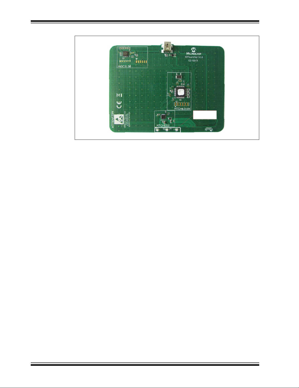
FIGURE 4-2: PCB BOTTOM VIEW
4.3 3D GESTURE RECOGNITION
3D gesture recognition is realized with Microchip’s single-chip gesture solution,
MGC3130. The MGC3130 is a gesture recognition, motion tracking and approach
detection controller based on Microchip’s patented GestIC technology. It enables user
command input with natural hand movements while utilizing the principles of electrical
near-field sensing. Please find more detailed information at
www.microchip.com/gestic.
MGC3130 is connected to four Rx frame electrodes (North, East, So uth and West)
located at the top of the PCB and one transmit (Tx) electrode which covers a full middle
layer of the PCB. The four Rx electrodes define the edges of the 3D sensing space (X
and Y direction). The sen sing space reaches a height of up to 70 mm (Z direction).
Inside this sensing space, the user can perform free space gestures which are
described in Table 3-2.
4.4 2D T OUCH PAD
The 2D touch functionality is reali zed with Microchip’s MTCH63104, a PIC32-based
PCAP controller. It handles 12 Rx and 16 Tx nodes, which are located in the center of
the PCB (top layer) in between the 3D Ges tIC Rx electrodes. T he edges of the touch
pad area are marked by a raised line on the top cover.
In order to ensure system stability and r obustness, the PCAP Tx signal is driven by
Microchip’s MTCH652. MTCH652 is a Tx voltage booster solution which drives the Tx
signal up to 18V.
The 2D touch pad allows tracki ng of u p to ten finger s sim ultaneous ly. Besides the 2D
multi-finger tracking functionality, a variety of surface gestures are implemented. These
surface gestures allow for example two-finger scrolling. A complete overview of the 2D
gestures is given in Table 3-1.
DS40001763A-page 14 2014 Microchip Technology Inc.
Page 15

4.5 COMMUNICATION
MTCH63104
MGC3130
I
2
C
TM
TS
HANDSHAKE LINE 1
HANDSHAKE LINE 2
OE
SPI
OSCIN
USB HOST
(PC)
USB HID
MTCH652
Hardware
MGC3130 and MTCH63104 communicate via I2C™ – MTCH63104 as master and
MGC3130 as slave. In addition to the I
2
C lines, there are two handsha ke lines which
are used for the handover proces s between 3D and 2D operation. 2D as well as 3D
information is sent to the P C by MTCH 63104 v ia the USB. Here by, MTCH 63104 a cts
as a HID device.
FIGURE 4-3: COMMUNICATION BLOCK DIAGRAM
4.6 OPERATING MODES AND LED INDICATIONS
FIGURE 4-4: LEDS SEEN FROM THE BACK
Three LEDs are plac ed on the bottom of the 3DTouchPad to indicate the operating
mode (see Figure 4-4).
• LED 3 (indication for 3D mode): Free space gestures such a s flicks or Airw heel
will be detected.
• LED 2 (indication for 2D mode): If the user touches the surface of the pad, the
mode will change automatical ly from 3D to 2D and this LED will light up. LED 3
will be switched off. Multi-finger tracking as well as surface gestures will be
detected in this mode.
• LED 1 (indic a ti o n for Debug mode): If Debug mode is enabled, neither 2D nor 3D
information will be forwarded to the Windows HID interface. Hence, all built-in
Windows OS control features are disabled. 2D and 3D information can be
monitored in the 3DTouchPad GUI without effects on the OS. The Debug mode
can be enabled and disabled in the 3DTouchPad GUI.
2014 Microchip Technology Inc. DS40001763A-page 15
Page 16

Chapter 5. 3DTouchPad GUI
The History window
displays previous
events
Control Panel
The 3D Signal Level window
indicates signal level for
each GestICΠ Rx electrode
If a 3D gesture ŝƐ detected,
it will be shown in the 3D
Gesture window
The XY window
shows 2D Multi
Finger Tracking
The XYZ window shows
hand position in 3D
Status Bar
5.1 INTRODUCTION
The 3DTouchPad GUI is a central element of the development process using the
3DTouchPad. It can be downloaded for free from the 3DTouchPad site at
www.microchip.com/3dtouchpad.
The 3DTouchPad GUI provides two main sections:
• Colibri Suite tab
• Setup tab
Using the Colibri Suite tab, the user can observe and assess 2D as well as 3D
performance. In the Setup tab, the user can perform f irmware updates for both the
MGC3130 and MTCH63104 devices.
5.2 COLIBRI SUITE TAB
FIGURE 5-1: COLIBRI SUITE TAB
3DTouchPad USER’S GUIDE
DS40001763A-page 16 2014 Microchip Technology Inc.
Page 17

3DTouchPad GUI
The Colibri Suite tab is divided into the following windows:
• The XY window, showing 2D multi-finger tracking
• The XYZ window, indicating the hand position in 3D mode
• The 3D Signal Level window, showing the signal level for each GestIC Rx
electrode
• The History window, displaying 2D and 3D events in chronological order
• The 3D Gesture window, displaying all 3D gestures after successful detection
Please see Table 5-1 for a list of all available free space gestures.
TABLE 5-1: 3D GESTURES – THE 3D GESTURE WINDOW
Symbol Gesture
Flicks in all four directions
Airwheel with counter (clockwise and
counterclockwise)
Garbage model
For more information on these gestures, please refer to the “MGC3130 Aurea
Graphical User Interface User’s Guide” (DS40001681).
Note: Only 3D gestures will be shown in the GUI. 2D surface gestures such as
taps or swipes are not visualized.
2014 Microchip Technology Inc. DS40001763A-page 17
Page 18

3DTouchPad User’s Guide
Gesture
Indication
GestICΠ &irmware
sersion
Operation
Mode
Processing
Indication
Noise
Indication
The control panel on the top right side offers additional functionality. Please see
Table 5-2 for the description of the control panel items.
TABLE 5-2: CONTROL PANEL ITEMS
Icon Description
Enable/Disable Debug mode
Connect/Disconnect from 3DTouchPad GUI
Reset MGC3130
About
Link to 3DT ouchPad site (
www.microchip.com/3dtouchpad)
The status bar is located at th e bottom side of the GUI. It pr ovides informati on about
the recent status of the 3DTouchPad (see Figure 5-2).
The following information is displayed from left to right:
• Gesture Indication, which shows the latest recognized 3D free space gesture
• MGC3130 Firmware Version
• Operation Mode Indication, which lights up if the 3DTouchPad is in 2D mode; the
indication is off if the pad is in 3D mode
• Noise Indication, which flashes when high noise is detected
• Processing Indication, which shows if the 3DTouchPad is working
FIGURE 5-2: STATUS BAR
DS40001763A-page 18 2014 Microchip Technology Inc.
Page 19

5.3 SETUP TAB
The firmware for both the MGC3130 and MTCH63104 devices can be updated by
clicking Firmware Update.
The 3DTouchPad GUI will then automatically update the latest firmware file for
MGC3130 and MTCH63104.
3DTouchPad GUI
2014 Microchip Technology Inc. DS40001763A-page 19
Page 20

Worldwide Sales and Service
AMERICAS
Corporate Office
2355 West Chandler Blvd.
Chandler, AZ 85224-6199
Tel: 480-792-7200
Fax: 480-792-7277
Te chn ica l Support:
http://www.microchip.com/
support
Web Address:
www.microchip.com
Atlanta
Duluth, GA
Tel: 678-957-9614
Fax: 678-957-1455
Austin, TX
Tel: 512-257-3370
Boston
Westborough, MA
Tel: 774-760-0087
Fax: 774-760-0088
Chicago
Itasca, IL
Tel: 630-285-0071
Fax: 630-285-0075
Cleveland
Independence, OH
Tel: 216-447-0464
Fax: 216-447-0643
Dallas
Addison, TX
Tel: 972-818-7423
Fax: 972-818-2924
Detroit
Novi, MI
Tel: 248-848-4000
Houston, TX
Tel: 281-894-5983
Indianapolis
Noblesville, IN
Tel: 317-773-8323
Fax: 317-773-5453
Los Angeles
Mission Viejo, CA
Tel: 949-462-9523
Fax: 949-462-9608
New Yor k , NY
Tel: 631-435-6000
San Jose, CA
Tel: 408-735-9110
Canada - Toronto
Tel: 905-673-0699
Fax: 905-673-6509
ASIA/PACIFIC
Asia Pacific Office
Suites 3707-14, 37th Floor
Tower 6, The Gateway
Harbour City, Kowloon
Hong Kong
Tel: 852-2943-5100
Fax: 852-2401-3431
Australia - Sydney
Tel: 61-2-9868-6733
Fax: 61-2-9868-6755
China - Beijing
Tel: 86-10-8569-7000
Fax: 86-10-8528-2104
China - Chengdu
Tel: 86-28-8665-5511
Fax: 86-28-8665-7889
China - Chongqing
Tel: 86-23-8980-9588
Fax: 86-23-8980-9500
China - Hangzhou
Tel: 86-571-8792-8115
Fax: 86-571-8792-8116
China - Hong Kong SAR
Tel: 852-2943-5100
Fax: 852-2401-3431
China - Nanjing
Tel: 86-25-8473-2460
Fax: 86-25-8473-2470
China - Qingdao
Tel: 86-532-8502-7355
Fax: 86-532-8502-7205
China - Shanghai
Tel: 86-21-5407-5533
Fax: 86-21-5407-5066
China - Shenyang
Tel: 86-24-2334-2829
Fax: 86-24-2334-2393
China - Shenzhen
Tel: 86-755-8864-2200
Fax: 86-755-8203-1760
China - Wuhan
Tel: 86-27-5980-5300
Fax: 86-27-5980-5118
China - Xian
Tel: 86-29-8833-7252
Fax: 86-29-8833-7256
China - Xiamen
Tel: 86-592-2388138
Fax: 86-592-2388130
China - Zhuhai
Tel: 86-756-3210040
Fax: 86-756-3210049
ASIA/PACIFIC
India - Bangalore
Tel: 91-80-3090-4444
Fax: 91-80-3090-4123
India - New Delhi
Tel: 91-11-4160-8631
Fax: 91-11-4160-8632
India - Pune
Tel: 91-20-3019-1500
Japan - Osaka
Tel: 81-6-6152-7160
Fax: 81-6-6152-9310
Japan - Tokyo
Tel: 81-3-6880- 3770
Fax: 81-3-6880-3771
Korea - Daegu
Tel: 82-53-744-4301
Fax: 82-53-744-4302
Korea - Seoul
Tel: 82-2-554-7200
Fax: 82-2-558-5932 or
82-2-558-5934
Malaysia - Kuala Lumpur
Tel: 60-3-6201-9857
Fax: 60-3-6201-9859
Malaysia - Penang
Tel: 60-4-227-8870
Fax: 60-4-227-4068
Philippines - Manila
Tel: 63-2-634-9065
Fax: 63-2-634-9069
Singapore
Tel: 65-6334-8870
Fax: 65-6334-8850
Tai wan - Hsin Chu
Tel: 886-3-5778-366
Fax: 886-3-5770-955
Taiwan - Kaohsiung
Tel: 886-7-213-7830
Taiwan - Taipei
Tel: 886-2-2508-8600
Fax: 886-2-2508-0102
Thailand - Bangkok
Tel: 66-2-694-1351
Fax: 66-2-694-1350
EUROPE
Austria - Wels
Tel: 43-7242-2244-39
Fax: 43-7242-2244-393
Denmark - Copenhagen
Tel: 45-4450-2828
Fax: 45-4485-2829
France - Paris
Tel: 33-1-69-53-63-20
Fax: 33-1-69-30-90-79
Germany - Dusseldorf
Tel: 49-2129-3766400
Germany - Munich
Tel: 49-89-627-144-0
Fax: 49-89-627-144-44
Germany - Pforzheim
Tel: 49-7231-424750
Italy - Milan
Tel: 39-0331-742611
Fax: 39-0331-466781
Italy - Venice
Tel: 39-049-7625286
Netherlands - Drunen
Tel: 31-416-690399
Fax: 31-416-690340
Poland - Wars a w
Tel: 48-22-3325737
Spain - Madrid
Tel: 34-91-708-08-90
Fax: 34-91-708-08-91
Sweden - Stockholm
Tel: 46-8-5090-4654
UK - Wokingham
Tel: 44-118-921-5800
Fax: 44-118-921-5820
03/25/14
DS40001763A-page 20 2014 Microchip Technology Inc.
Page 21

Mouser Electronics
Authorized Distributor
Click to View Pricing, Inventory, Delivery & Lifecycle Information:
Microchip:
DM160225
 Loading...