

Page 1
MPLAB® XC8 PIC® Assembler User's Guide
Notice to Customers
All documentation becomes dated and this manual is no exception. Microchip tools and documentation are constantly
evolving to meet customer needs, so some actual dialogs and/or tool descriptions can differ from those in this
document. Please refer to our web site (https://www.microchip.com) to obtain the latest documentation available.
Documents are identified with a “DS” number. This number is located on the bottom of each page, in front of the page
number. The numbering convention for the DS number is “DSXXXXXA,” where “XXXXX” is the document number
and “A” is the revision level of the document.
For the most up-to-date information on development tools, see the MPLAB® IDE online help. Select the Help menu,
and then Topics to open a list of available online help files.
© 2020 Microchip Technology Inc.
User Guide
DS50002974A-page 1
Page 2

Table of Contents
Notice to Customers.......................................................................................................................................1
1. Preface....................................................................................................................................................4
1.1. Conventions Used in This Guide..................................................................................................4
1.2. Recommended Reading...............................................................................................................5
1.3. Document Revision History.......................................................................................................... 5
2. Assembler Overview............................................................................................................................... 6
2.1. Device Description....................................................................................................................... 6
2.2. Compatible Development Tools....................................................................................................6
3. Assembler Driver.....................................................................................................................................7
3.1. Single-step Assembly...................................................................................................................7
3.2. Multi-step Assembly..................................................................................................................... 7
3.3. Assembler Option Descriptions.................................................................................................... 8
4. MPLAB XC8 Assembly Language........................................................................................................ 19
4.1. Assembly Instruction Deviations................................................................................................ 19
4.2. Statement Formats.....................................................................................................................22
4.3. Characters..................................................................................................................................23
4.4. Comments.................................................................................................................................. 23
4.5. Constants................................................................................................................................... 23
4.6. Identifiers....................................................................................................................................24
4.7. Expressions................................................................................................................................25
4.8. Program Sections.......................................................................................................................26
4.9. Assembler Directives..................................................................................................................27
5. Assembler Features.............................................................................................................................. 45
5.1. Preprocessor Directives............................................................................................................. 45
5.2. Assembler-provided Psects........................................................................................................46
5.3. Default Linker Classes............................................................................................................... 46
5.4. Linker-Defined Symbols............................................................................................................. 48
5.5. Assembly List Files.....................................................................................................................48
6. Linker.................................................................................................................................................... 50
6.1. Operation....................................................................................................................................50
6.2. Psects and Relocation................................................................................................................56
6.3. Map Files....................................................................................................................................56
7. Utilities...................................................................................................................................................61
7.1. Archiver/Librarian....................................................................................................................... 61
7.2. Hexmate..................................................................................................................................... 62
The Microchip Website.................................................................................................................................76
Product Change Notification Service............................................................................................................76
Customer Support........................................................................................................................................ 76
© 2020 Microchip Technology Inc.
User Guide
DS50002974A-page 2
Page 3

Microchip Devices Code Protection Feature................................................................................................ 76
Legal Notice................................................................................................................................................. 76
Trademarks.................................................................................................................................................. 77
Quality Management System....................................................................................................................... 77
Worldwide Sales and Service.......................................................................................................................78
© 2020 Microchip Technology Inc.
User Guide
DS50002974A-page 3
Page 4
1. Preface
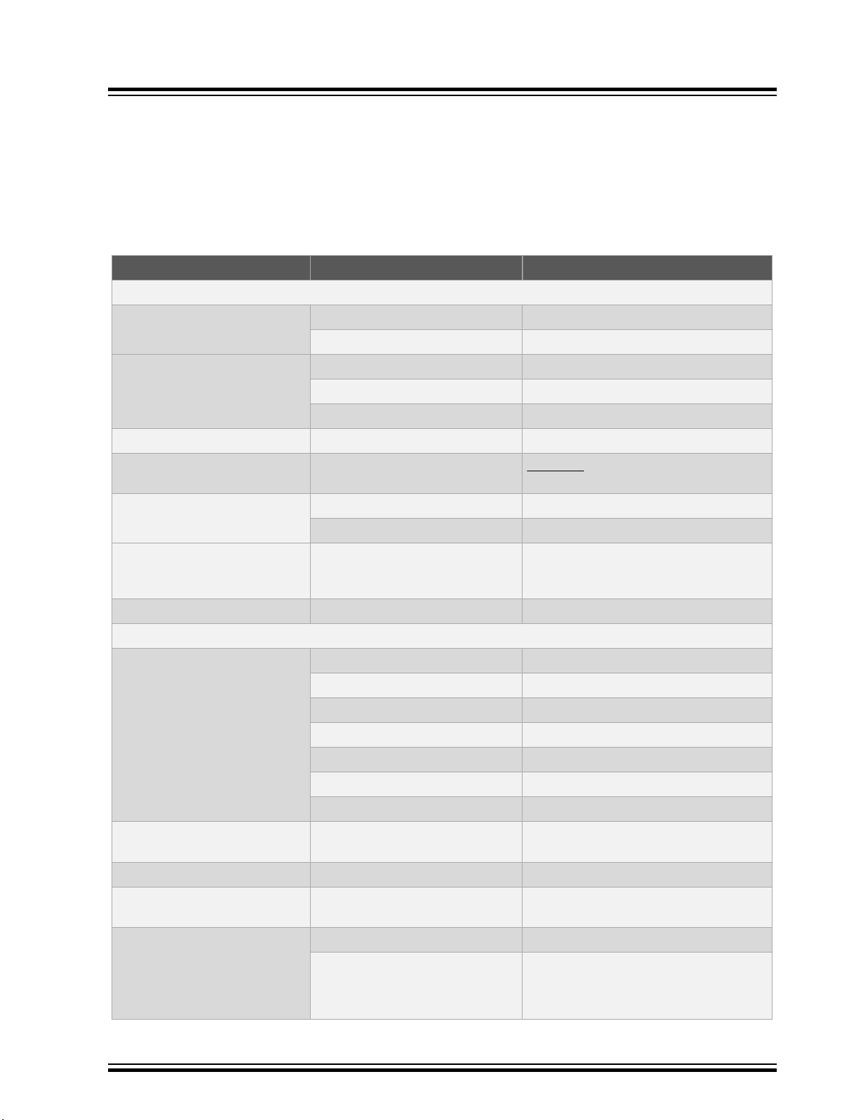
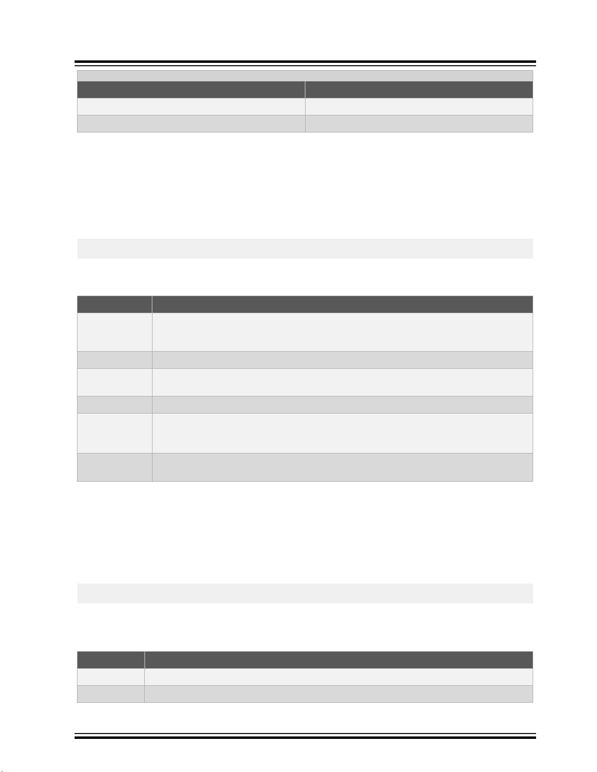
1.1 Conventions Used in This Guide
The following conventions may appear in this documentation:
Table 1-1. Documentation Conventions
Description Represents Examples
Arial font:
Italic characters Referenced books MPLAB® IDE User’s Guide
Emphasized text ...is the only compiler...
Initial caps A window the Output window
A dialog the Settings dialog
A menu selection select Enable Programmer
Quotes A field name in a window or dialog “Save project before build”
Preface
Underlined, italic text with right
angle bracket
Bold characters A dialog button Click OK
N‘Rnnnn A number in verilog format, where
Text in angle brackets < > A key on the keyboard Press <Enter>, <F1>
Courier New font:
Plain Courier New Sample source code
Italic Courier New A variable argument file.o, where file can be any valid
Square brackets [ ] Optional arguments
Curly brackets and pipe
character: { | }
Ellipses... Replaces repeated text
A menu path File>Save
A tab Click the Power tab
4‘b0010, 2‘hF1
N is the total number of digits, R is
the radix and n is a digit.
#define START
Filenames
File paths
Keywords
Command-line options
Bit values
Constants
Choice of mutually exclusive
arguments; an OR selection
Represents code supplied by user
autoexec.bat
c:\mcc18\h
_asm, _endasm, static
-Opa+, -Opa-
0, 1
0xFF, ‘A’
filename
mcc18 [options] file [options]
errorlevel {0|1}
var_name [, var_name...]
void main (void)
{ ...
}
© 2020 Microchip Technology Inc.
User Guide
DS50002974A-page 4
Page 5

1.2 Recommended Reading
This user’s guide describes the use and features of the MPLAB XC8 PIC Assembler. The following Microchip
documents are available and recommended as supplemental reference resources.
MPLAB® XC8 PIC Assembler Migration Guide
This guide is for customers who have MPASM projects and who wish to migrate them to the MPLAB XC8 PIC
assembler. It describes the nearest equivalent assembler syntax and directives for MPASM code.
MPLAB® XC8 PIC Assembler Guide For Embedded Engineers
This guide is a getting started guide, describing example projects and commonly used coding sequences used by the
MPLAB XC8 PIC assembler. Use this guide if you need to develop new projects using the assembler.
MPLAB® XC8 C Compiler Release Notes for PIC MCU
For the latest information on changes and bug fixes to this assembler, read the Readme file in the docs subdirectory
of the MPLAB XC8 installation directory.
Development Tools Release Notes
For the latest information on using other development tools, read the tool-specific Readme files in the docs
subdirectory of the MPLAB X IDE installation directory.
Preface
1.3 Document Revision History
Revision A (March 2020)
• Initial release of this document, based on the assembler chapter from the MPLAB® XC8 C Compiler User's
Guide (DS50002737).
© 2020 Microchip Technology Inc.
User Guide
DS50002974A-page 5
Page 6

2. Assembler Overview
The MPLAB XC8 PIC Assembler is a free-standing cross assembler and linker package, supporting all 8-bit PIC
microcontrollers.
2.1 Device Description
This guide describes the MPLAB XC8 PIC Assembler's support for all 8-bit Microchip PIC devices with baseline, midrange, enhanced mid-range and PIC18 cores. The following descriptions indicate the distinctions within those device
cores:
The baseline core uses a 12-bit-wide instruction set and is available in PIC10, PIC12 and PIC16 part numbers.
The enhanced baseline core also uses a 12-bit instruction set, but this set includes additional instructions. Some of
the enhanced baseline chips support interrupts and the additional instructions used by interrupts. These devices are
available in PIC12 and PIC16 part numbers.
The mid-range core uses a 14-bit-wide instruction set that includes more instructions than the baseline core. It has
larger data memory banks and program memory pages, as well. It is available in PIC12, PIC14 and PIC16 part
numbers.
The Enhanced mid-range core also uses a 14-bit-wide instruction set but incorporates additional instructions and
features. There are both PIC12 and PIC16 part numbers that are based on the Enhanced mid-range core.
The PIC18 core instruction set is 16 bits wide and features additional instructions and an expanded register set.
PIC18 core devices have part numbers that begin with PIC18.
See 3.3.22 Print-devices for information on finding the full list of devices that are supported by the assembler.
Assembler Overview
®
2.2 Compatible Development Tools
The assembler works with many other Microchip tools, including:
• The MPLAB X IDE (https://www.microchip.com/mplab/mplab-x-ide)
• The MPLAB X Simulator
• The Command-line MDB Simulator—see the Microchip Debugger (MDB) User’s Guide (DS52102)
• All Microchip debug tools and programmers (https://www.microchip.com/mplab/development-boards-and-tools)
• Demonstration boards and Starter kits that support 8-bit devices
© 2020 Microchip Technology Inc.
User Guide
DS50002974A-page 6
Page 7

3. Assembler Driver
The name of the command-line driver used by the MPLAB XC8 PIC Assembler is pic-as.
This driver can be invoked to perform both assembly and link steps and is the application called by development
environments, such as the MPLAB X IDE, to build assembly projects.
The pic-as driver has the following basic command format:
pic-as [options] files [libraries]
Throughout this manual, it is assumed that the assembler applications are in your console’s search path or that the
full path is specified when executing the application.
It is customary to declare options (identified by a leading dash “-” or double dash “--”) before the files’ names;
however, this is not mandatory.
The formats of the options are supplied in 3.3 Assembler Option Descriptions along with corresponding
descriptions of the options' function.
The files can be an assortment of assembler source files and precompiled intermediate files. While the order in
which these files are listed is not important, it can affect the allocation of code or data and can affect the names of
some of the output files.
The libraries is a list of user-defined library files that will be searched by the compiler. The order of these files will
determine the order in which they are searched. It is customary to insert the libraries after the list of source files;
however, this is not mandatory.
Assembler Driver
3.1 Single-step Assembly
Assembly of one or more source files can be performed in just one step using the pic-as driver.
The following command will build both the assembly source files, passing these files to the appropriate internal
applications, then link the generated code to form the final output.
pic-as -mcpu=16F877A main.S mdef.s
The driver will compile all source files, regardless of whether they have changed since the last build. Development
environments (such as MPLAB® X IDE) and make utilities must be employed to achieve incremental builds (see 3.2
Multi-step Assembly).
Unless otherwise specified, a HEX file and ELF file are produced as the final output. The intermediate files remain
after compilation has completed, but most other temporary files are deleted, unless you use the -save-temps
option (see 3.3.26 Save-temps Option) which preserves all generated files. Note that some generated files can be in
a different directory than your project source files (see also 3.3.21 O: Specify Output File).
3.2 Multi-step Assembly
A multi-step assembly method can be employed to achieve an incremental build of your project. Make utilities take
note of which source files have changed since the last build and only rebuild these files to speed up assembly. From
within MPLAB X IDE, you can select an incremental build (Build Project icon), or fully rebuild a project (Clean and
Build Project icon).
Make utilities typically call the assembler multiple times: once for each source file to generate an intermediate file and
once to perform the link step.
The option -c is used to create an intermediate file. This option stops after the assembler application has executed,
and the resulting object output file will have a .o extension.
The intermediate files can then be specified to the driver during the second stage of compilation, when they will be
passed to the linker.
© 2020 Microchip Technology Inc.
User Guide
DS50002974A-page 7
Page 8
The first two of the following command lines build an intermediate file for each assembly source file, then these
intermediate files are passed to the driver again to be linked in the last command.
pic-as -mcpu=16F877A -c main.s
pic-as -mcpu=16F877A -c io.s
pic-as -mcpu=16F877A main.o io.o
As with any assembler, all the files that constitute the project must be present when performing the second (link)
stage of compilation.
You might also wish to generate intermediate files to construct your own library files. See 7.1 Archiver/Librarian for
more information on library creation.
3.3 Assembler Option Descriptions
Most aspects of the build process can be controlled using options passed to the assembler's command-line driver,
pic-as.
All options are case sensitive and are identified by leading single or double dash character, e.g. -o or --version.
Use the --help option to obtain a brief description of accepted options on the command line.
If you are compiling from within the MPLAB X IDE, it will issue explicit options to the assembler that are based on the
selections in the project's Project Properties dialog. The default project options might be different to the default
options used by the assembler when running on the command line, so you should review your IDE properties to
ensue that they are acceptable.
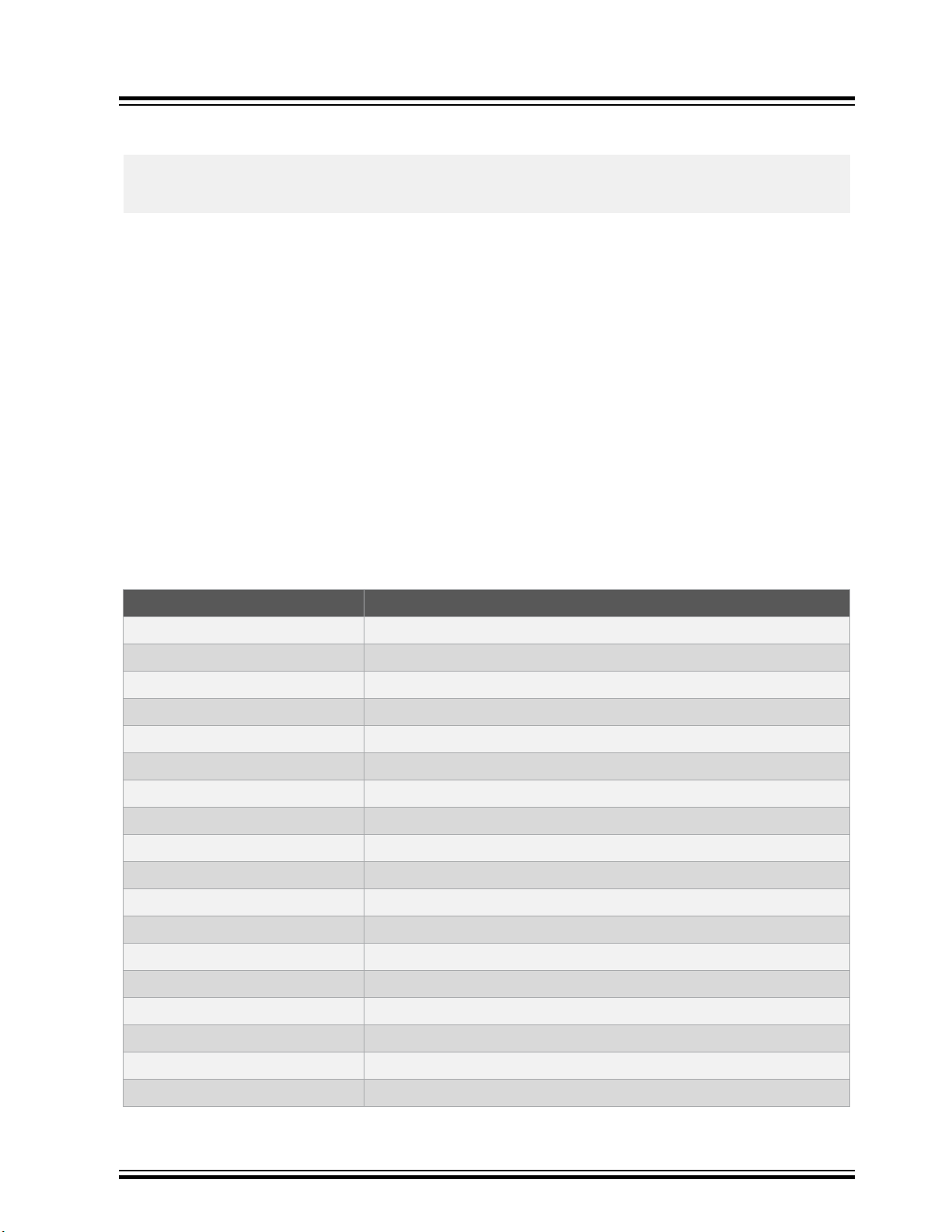
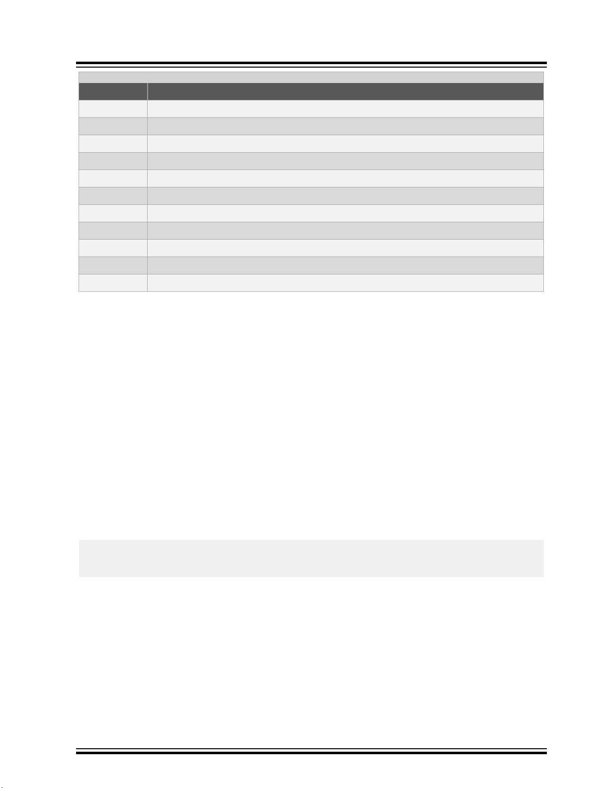
The summary of all available driver options tabulated below is followed by a detailed description of each option.
Table 3-1. PIC Assembler Driver Options
Assembler Driver
Option Controls
-###
-c
-mcallgraph=type
-mchecksum=specs
-mcpu=device
-D
-mdfp=path
-dM
-m[no-]download
-E
--fill=options
-gformat
-H
--help
-I
-misa
-l
-L
Display of application command-lines but with no execution
Generation of an intermediate object file
The type of callgraph printed in the map file
The generation and placement of a checksum or hash
The target device that code will be built for
Definition of preprocessor symbols
Which device family pack to use
List all defined macros
How the final HEX file is conditioned
The generation of preprocessed-only files
Filling of unused memory
The type of debugging information generated
List included header files
Display help information only
Directories searched for headers
Select PIC18 instruction set
Which libraries are scanned
Directories searched for libraries
© 2020 Microchip Technology Inc.
User Guide
DS50002974A-page 8
Page 9
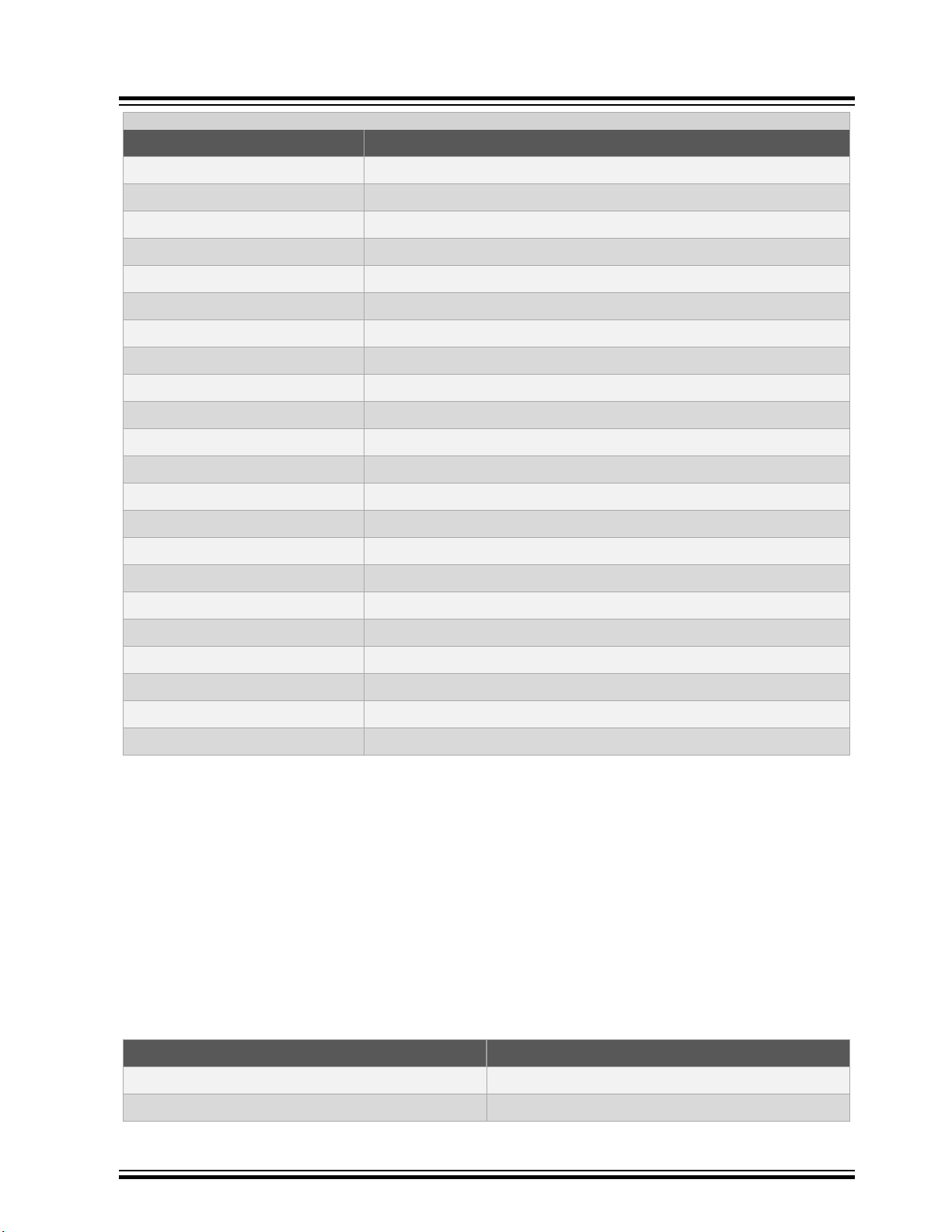
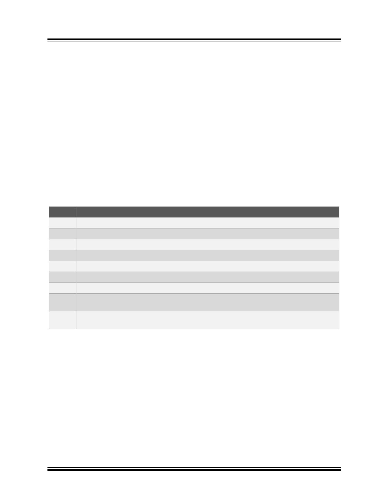
...........continued
Option Controls
-fmax-errors
-mmaxichip
-o
-mprint-devices
-mram=ranges
-mreserve=ranges
-mrom=ranges
-save-temps
-mserial=options
-msummary=types
-U
-v
--version
-w
-mwarn=level
-Wa,option
-Wp,option
-Wl,option
-xlanguage
-Xassembler option
-Xpreprocessor option
-Xlinker option
Number of errors before aborting
Use of a hypothetical device with full memory
Specify output file name
Chip information only
Data memory that is available for the program
What memory should be reserved
Program memory that is available for the program
Whether intermediate files should be kept after compilation
The insertion of a serial number in the output
What memory summary information is produced
The undefining of preprocessor symbols
Verbose compilation output
Display of assembler version information
The suppression of all warning messages
The threshold at which warnings are output
Options passed to the assembler
Options passed to the preprocessor
Options passed to the linker
The language in which the source files are interpreted
Options passed to the assembler
Options passed to the preprocessor
System-specific options to passed to the linker
Assembler Driver
3.3.1 ### Option
The -### option is similar to -v, but the commands are not executed. This option allows you to see the assembler’s
command lines without executing the assembler.
3.3.2 C: Compile To Intermediate File
The -c option is used to generate an intermediate file for each source file listed on the command line.
This option is often used to facilitate multi-step builds using a make utility.
3.3.3 Callgraph Option
The -mcallgraph=type option controls what sort of call graph is printed in the map file. The available types are
shown in the table.
Table 3-2. Callgraph types
Type Produces
none
crit
© 2020 Microchip Technology Inc.
No call graph
Only critical paths in the callgraph
User Guide
DS50002974A-page 9
Page 10
...........continued
Type Produces
std
full
The callgraph is generated by the linker, primarily for the purposes of allocating memory to objects in the compiled
stack. Those routines defining stack objects that are not overlaid with other stack objects and that are hence
contributing to the program's data memory usage are considered as being on a critical path.
3.3.4 Checksum Option
The -mchecksum=specs option will calculate a hash value (for example checksum or CRC) over the address range
specified and stores the result in the hex file at the indicated destination address. The general form of this option is as
follows.
-mchecksum=start-end@destination[,specifications]
The following specifications are appended as a comma-separated list to this option.
Table 3-3. Checksum Arguments
Argument Description
width=n
offset=nnnn
algorithm=n
polynomial=nn
code=nn
Assembler Driver
Standard, short-form call graph (default)
Full call graph
Selects the width of the hash result in bytes for non-Fletcher algorithms, or in bits for SHA
algorithms. A negative width will store the result in little-endian byte order; positive widths in bigendian order. Result widths from one to four bytes are permitted, or 256 bits for SHA algorithms.
Specifies an initial value or offset added to the checksum.
Selects one of the hash algorithms implemented in Hexmate. The selectable algorithms are
described in Table 7-3.
Selects the polynomial value when using CRC algorithms
Specifies a hexadecimal code that will trail each byte in the result. This can allow each byte of
the result to be embedded within an instruction, for example code=34 will embed the result in a
retlw instruction on Mid-range devices.
revword=n
The start, end and destination attributes are, by default, hexadecimal constants. The addresses defining the
input range are typically made multiples of the algorithm width. If this is not the case, zero bytes will pad any missing
input word locations.
If an accompanying --fill option (3.3.11 Fill Option) has not been specified, unused locations within the specified
address range will be automatically filled with 0xFFF for baseline devices, 0x3FFF for mid-range devices, or 0xFFFF
for PIC18 devices. This is to remove any unknown values from the calculations and ensure the accuracy of the result.
For example:
-mchecksum=800-fff@20,width=1,algorithm=2
will calculate a 1-byte checksum from address 0x800 to 0xfff and store this at address 0x20. A 16-bit addition
algorithm will be used. Table 3-9 shows the available algorithms and 7.2.2 Hash Functions describes these in detail.
Table 3-4. Checksum Algorithm Selection
Selector Algorithm description
-5
-4
© 2020 Microchip Technology Inc.
Read data in reverse byte order from n-byte wide words. Currently this value can be 0 or 2. A
value of 0 disables the reverse-read feature.
Reflected cyclic redundancy check (CRC)
Subtraction of 32 bit values from initial value
User Guide
DS50002974A-page 10
Page 11
Assembler Driver
...........continued
Selector Algorithm description
-3
-2
-1
1
2
3
4
5
7
8
10
The hash calculations are performed by the Hexmate application. The information in this driver option is passed to
the Hexmate application when it is executed.
Subtraction of 24 bit values from initial value
Subtraction of 16 bit values from initial value
Subtraction of 8 bit values from initial value
Addition of 8 bit values from initial value
Addition of 16 bit values from initial value
Addition of 24 bit values from initial value
Addition of 32 bit values from initial value
Cyclic redundancy check (CRC)
Fletcher’s checksum (8 bit calculation, 2-byte result width)
Fletcher’s checksum (16 bit calculation, 4-byte result width)
SHA-2 (currently only SHA256 is supported)
3.3.5 Cpu Option
The -mcpu=device option must be used to specify the target device when building. This is the only option that is
mandatory.
For example -mcpu=18f6722 will select the PIC18F6722 device. To see a list of supported devices that can be used
with this option, use the -mprint-devices option (3.3.22 Print-devices).
3.3.6 D: Define a Macro
The -Dmacro=text option allows you to define preprocessor macros. For macros to be subsequently processed,
the source files must be preprocessed by having them use a .S file extension or by using the -xassembler-wth-
cpp option.
A space may be present between the option and macro name.
With no =text specified in the option, this option defines a preprocessor macro called macro that will be considered
to have been defined by any preprocessor directive that checks for such a definition (e.g. the #ifdef directive) and
that will expand to be the value 1 if it is used in a context where it will be replaced. For example, when using the
option, -DMY_MACRO (or -D MY_MACRO) and supplying the following code:
#ifdef MY_MACRO
movlw MY_MACRO;
#endif
the movlw instruction will be assembled and the value 1 will be assigned to the W register.
When the replacement, text, is specified with the option, the macro will subsequently expand to be the replacement
specified with the option. So if the above example code was compiled with the option -DMY_MACRO=0x55, then the
instruction would be assembled as: movlw 0x55
All instances of -D on the command line are processed before any -U options.
3.3.7 dM: Preprocessor Debugging Dumps Option
The -dM option has the preprocessor produce macro definitions that are in effect at the end of preprocessing. This
option should be used in conjunction with the -E option, and if you want the output directed to a file, use also the -o
option.
© 2020 Microchip Technology Inc.
User Guide
DS50002974A-page 11
Page 12

3.3.8 Dfp Option
The -mdfp=path option indicates that device-support for the target device (indicated by the -mcpu option) should
be obtained from the contents of a Device Family Pack (DFP), where path is the path to the xc8 sub-directory of the
DFP.
When this option has not been used, the pic-as driver will where possible use the device-specific files provided in
the assembler distribution.
The MPLAB X IDE automatically uses this option to inform the assembler of which device-specific information to use.
Use this option on the command line if additional DFPs have been obtained for the assembler.
A DFP might contain such items as device-specific header files, configuration bit data and libraries, letting you take
advantage of features on new devices without you having to otherwise update the assembler. DFPs never contain
executables or provide bug fixes or improvements to any existing tools or standard library functions.
When using this option, the preprocessor will search for include files in the <DFP>/xc8/pic/include/proc and
<DFP>/xc8/pic/include directories first, then search the standard search directories.
3.3.9 Download Option
The -mdownload option conditions the Intel HEX for use by bootloader. The -mdownload-hex option is equivalent
in effect.
When used, this option will pad data records in the Intel HEX file to 16-byte lengths and will align them on 16-byte
boundaries.
The default operation is to not modify the HEX file and this can be made explicit using the option -mno-download.
(-mno-download-hex)
Assembler Driver
3.3.10 E: Preprocess Only
The -E option is used to generate preprocessed assembly source files (also called modules or translation units).
When this option is used, the build sequence will terminate after the preprocessing stage, leaving behind files with
the same basename as the corresponding source file and with a .i extension.
You might check the preprocessed source files to ensure that preprocessor macros have expanded to what you think
they should. The option can also be used to create assembly source files that do not require any separate header
files. This is useful when sending files to a colleague or to obtain technical support without sending all the header
files, which can reside in many directories.
3.3.11 Fill Option
The --fill=options option allows you to fill unused memory with specified values in a variety of ways.
This option is functionally identical to Hexmate's -fill option. For more detailed information and advanced controls
that can be used with this option, refer to 7.2.1.11 Fill.
3.3.12 G: Produce Debugging Information Option
The -gformat option instructs the assembler to produce additional information, which can be used by hardware
tools to debug your program.
The support formats are tabulated below.
Table 3-5. Supported Debugging File Formats
Format Debugging file format
-gcoff
-gdwarf-3
-ginhx32
-ginhx032
COFF
ELF/Dwarf release 3
Intel HEX with extended linear address records, allowing use of addresses beyond 64kB
INHX32 with initialization of upper address to zero
By default, the assembler produces Dwarf release 3 files.
© 2020 Microchip Technology Inc.
User Guide
DS50002974A-page 12
Page 13

3.3.13 H: Print Header Files Option
The -H option prints to the console the name of each header file used, in addition to other normal activities.
3.3.14 Help
The --help option displays information on the pic-as assembler options, then the driver will terminate.
3.3.15 I: Specify Include File Search Path Option
The -Idir option adds the directory dir to the head of the list of directories to be searched for header files. A space
may be present between the option and directory name.
The option can specify either an absolute or relative path and it can be used more than once if multiple additional
directories are to be searched, in which case they are scanned from left to right. The standard system directories are
searched after scanning the directories specified with this option.
Under the Windows OS, the use of the directory backslash character may unintentionally form an escape sequence.
To specify an include file path that ends with a directory separator character and which is quoted, use -I "E:\\",
for example, instead of -I "E:\", to avoid the escape sequence \“. Note that MPLAB X IDE will quote any include
file path you specify in the project properties and that search paths are relative to the output directory, not the project
directory.
3.3.16 Isa Option
The -misa=set option allows the instruction set to be specified for PIC18 targets. The default is the standard PIC18
instruction set, a selection that can be made explicit by using -misa=std. Alternatively, the PIC18 extended
instruction set can be selected by using -misa=xinst. When used with a device that does not support the
requested instruction set, the option will be ignored and a warning issued.
Note that this option will permit the assembler to check for conformance of the assembly program to the selected
instruction set, but it does not instruct the device to operate with the selected instruction set. Use the XINST
configuration bit to enable this in your device.
Assembler Driver
3.3.17 L: Specify Library File Option
The -llibrary option looks for the specified file (with a .a extension) and scans this library archive for unresolved
symbols when linking.
The only difference between using an -l option (e.g., -lmylib) and specifying a file name on the command line
(e.g., mylib.a) is that the assembler will search for the library specified using -l in several directories, as specified
by the -L option.
3.3.18 L: Specify Library Search Path Option
The -Ldir option allows you to specify an additional directory to be searched for library files that have been
specified by using the -l option. The assembler will automatically search standard library locations, so you only need
to use this option if you are linking in your own libraries.
3.3.19 Max Errors
The -fmax-errors=n option sets the maximum number of errors each assembler application, as well as the driver,
will display before execution is terminated.
By default, up to 20 error messages will be displayed by each application before the assembler terminates. The
option -fmax-errors=10, for example, would ensure the applications terminate after only 10 errors.
3.3.20 Maxichip Option
The -mmaxichip option tells the assembler to build for a hypothetical device with the same physical core and
peripherals as the selected device, but with the maximum allowable memory resources permitted by the device
family. You might use this option if your program does not fit in your intended target device and you wish to get an
indication of the code or data size reductions needed to be able to program that device.
The assembler will normally terminate if the selected device runs out of program memory, data memory, or EEPROM.
When using this option, the program memory of PIC18 and mid-range devices will be maximized to extend from
© 2020 Microchip Technology Inc.
User Guide
DS50002974A-page 13
Page 14

address 0 to either the bottom of external memory or the maximum address permitted by the PC register, whichever
is lower. The program memory of baseline parts is maximized from address 0 to the lower address of the
Configuration Words.
The number of data memory banks is expanded to the maximum number of selectable banks as defined by the BSR
register (for PIC18 devices), RP bits in the STATUS register (for mid-range devices), or the bank select bits in the
FSR register (for baseline devices). The amount of RAM in each additional bank is equal to the size of the largest
contiguous memory area within the physically implemented banks.
If present on the device, EEPROM is maximized to a size dictated by the number of bits in the EEADR or NVMADR
register, as appropriate.
If required, check the map file (see 6.3 Map Files) to see the size and arrangement of the memory available when
using this option with your device.
Note: When using the -mmaxichip option, you are not building for a real device. The generated code may not load
or execute in simulators or the selected device. This option will not allow you to fit extra code into a device.
3.3.21 O: Specify Output File
The -o option specifies the base name and directory of the output file.
The option -o main.elf, for example, will place the generated output in a file called main.elf. The name of an
existing directory can be specified with the file name, for example -o build/main.elf, so that the output file will
appear in that directory.
You cannot use this option to change the type (format) of the output file.
Only the base name of the file specified with this option has significance. You cannot use this option to change the
extension of an output file.
Assembler Driver
3.3.22 Print-devices
The -mprint-devices option displays a list of devices the assembler supports.
The names listed are those devices that can be used with the -mcpu option. This option will only show those devices
that were officially supported when the assembler was released. Additional devices that might be available via device
family packs (DFPs) will not be shown in this list.
The assembler will terminate after the device list has been printed.
3.3.23 Ram Option
The -mram=ranges option is used to adjust the data memory that is specified for the target device. Without this
option, all the on-chip RAM implemented by the device is available, thus this option only needs be used if there are
special memory requirements. Specifying additional memory that is not in the target device might result in a
successful compilation, but can lead to code failures at runtime.
For example, to specify an additional range of memory to that already present on-chip, use:
-mram=default,+100-1ff
This will add the range from 100h to 1ffh to the on-chip memory. To only use an external range and ignore any onchip memory, use:
-mram=0-ff
This option can also be used to reserve memory ranges already defined as on-chip memory in the relevant chipinfo
file. To do this, supply a range prefixed with a minus character, -, for example:
-mram=default,-100-103
will use all the defined on-chip memory, but not use the addresses in the range from 100h to 103h for allocation of
RAM objects.
© 2020 Microchip Technology Inc.
User Guide
DS50002974A-page 14
Page 15

This option will adjust the memory ranges used by linker classes (see 6.1.1 A: Define Linker Class) . Any objects
contained in a psect that do not use the classes affected by this option might be linked outside the valid memory
specified by this option.
3.3.24 Reserve Option
The -mreserve=ranges option allows you to reserve memory normally used by the program. This option has the
general form:
-mreserve=space@start:end
where space can be either of ram or rom, denoting the data and program memory spaces, respectively; and start
and end are addresses, denoting the range to be excluded. For example, -mreserve=ram@0x100:0x101 will
reserve two bytes starting at address 100h from the data memory.
This option performs a similar task to the -mram and -mrom options, but it cannot be used to add additional memory
to that available for the program.
3.3.25 Rom Option
The -mrom=ranges option is used to change the default program memory that is specified for the target device.
Without this option, all the on-chip program memory implemented by the device is available, thus this option only
needs be used if there are special memory requirements. Specifying additional memory that is not in the target
device might result in a successful compilation, but can lead to code failures at runtime.
For example, to specify an additional range of memory to that on-chip, use:
Assembler Driver
-mrom=default,+100-2ff
This will add the range from 100h to 2ffh to the on-chip memory. To only use an external range and ignore any onchip memory, use:
-mrom=100-2ff
This option can also be used to reserve memory ranges already defined as on-chip memory in the chip configuration
file. To do this supply a range prefixed with a minus character, -, for example:
-mrom=default,-100-1ff
will use all the defined on-chip memory, but not use the addresses in the range from 100h to 1ffh for allocation of
ROM objects.
This option will adjust the memory ranges used by linker classes (see 6.1.1 A: Define Linker Class) . Any code or
objects contained in a psect that do not use the classes affected by this option might be linked outside the valid
memory specified by this option.
Note that some psects must be linked above a threshold address, most notably some psects that hold constqualified data. Using this option to remove the upper memory ranges can make it impossible to place these psects.
3.3.26 Save-temps Option
The -save-temps option instructs the assembler to keep temporary files after compilation has finished.
The intermediate files will be placed in the current directory and have a name based on the corresponding source file.
Thus, compiling foo.s with -save-temps would produce the foo.o object file.
The -save-temps=cwd option is equivalent to -save-temps.
The -save-temps=obj form of this option is similar to -save-temps, but if the -o option is specified, the
temporary files are placed in the same directory as the output object file. If the -o option is not specified, the -save-
temps=obj switch behaves like –save-temps.
© 2020 Microchip Technology Inc.
User Guide
DS50002974A-page 15
Page 16
3.3.27 Serial Option
The -mserial=options option allows a hexadecimal code to be stored at a particular address in program memory.
A typical task for this option might be to position a serial number in program memory.
The byte-width of data to store is determined by the byte-width of the hexcode parameter in the option. For example,
to store a one-byte value, 0, at program memory address 1000h, use -mserial=00@1000. To store the same value
as a four byte quantity use -mserial=00000000@1000.
This option is functionally identical to Hexmate's -serial option. For more detailed information and advanced
controls that can be used with this option (refer to 7.2.1.20 Serial).
3.3.28 Summary Option
The -msummary=type option selects the type of information that is included in the summary that is displayed once
the build is complete. By default, or if the mem type is selected, a memory summary with the total memory usage for
all memory spaces is shown.
A psect summary can be shown by enabling the psect type. This shows individual psects after they have been
grouped by the linker and the memory ranges they cover. Table 4-20 shows what summary types are available. The
default output printed corresponds to the mem setting.
SHA hashes for the generated hex file can also be shown using this option. These can be used to quickly determine
if anything in the hex file has changed from a previous build.
Table 3-6. Summary Types
Assembler Driver
Type Shows
psect
mem
class
hex
file
sha1
sha256
xml
xmlfull
If specified, the XML files contain information about memory spaces on the selected device, consisting of the space’s
name, addressable unit, size, amount used and amount free.
A summary of psect names and the addresses where they were linked will be shown.
A concise summary of memory used will be shown (default).
A summary of all classes in each memory space will be shown.
A summary of addresses and HEX files that make up the final output file will be shown.
Summary information will be shown on screen and saved to a file.
A SHA1 hash for the hex file.
A SHA256 hash for the hex file.
Summary information will be shown on the screen, and usage information for the main memory spaces
will be saved in an XML file.
Summary information will be shown on the screen, and usage information for all memory spaces will be
saved in an XML file.
3.3.29 U: Undefine Macros
The -Umacro option undefines the macro macro.
Any macro defined using -D will be undefined by this option. All -U options are evaluated after all -D options.
3.3.30 V: Verbose Compilation
The -v option specifies verbose compilation.
When this option is used, the name and path of the internal assembler applications will be displayed as they are
executed, followed by the command-line arguments that each application was passed.
You might use this option to confirm that your driver options have been processed as you expect, or to see which
internal application is issuing a warning or error.
© 2020 Microchip Technology Inc.
User Guide
DS50002974A-page 16
Page 17

3.3.31 Version
The --version option prints assembler version information then exits.
3.3.32 W: Disable all Warnings Option
The -w option inhibits all warning messages, and thus should be used with caution.
3.3.33 Wa: Pass Option To The Assembler Option
The -Wa,option option passes its option argument directly to the assembler. If option contains commas, it is split
into multiple options at the commas. For example -Wa,-a will request that the assembler produce an assembly list
file.
3.3.34 Warn Option
The -mwarn=level option is used to set the warning level threshold. Allowable warning levels range from -9 to 9.
The warning level determines how pedantic the assembler is about dubious type conversions and constructs. Each
warning has a designated warning level; the higher the warning level, the more important the warning message. If the
warning message’s warning level exceeds the set threshold, the warning is printed. The default warning level
threshold is 0 and will allow all normal warning messages.
Use this option with care as some warning messages indicate code that is likely to fail during execution, or
compromise portability.
Assembler Driver
3.3.35 Wp: Pass Option To The Preprocessor Option
The -Wp,option option passes option to the preprocessor, where it will be interpreted as a preprocessor option. If
option contains commas, it is split into multiple options at the commas.
3.3.36 WL: Pass Option To The Linker Option
The -Wl,option option passes option to the linker where it will be interpreted as a linker option. If option
contains commas, it is split into multiple options at the commas.
3.3.37 X: Specify Source Language Option
The -xlanguage option allows you to specify that the source files that follow are written in the specified language,
regardless of the extension they use.
The languages allowed by the PIC Assembler are tabulated below.
Table 3-7. Language options
Language Description
assembler
assembler-with-cpp
For example, the command:
pic-as -mcpu=18f4520 -xassembler-with-cpp init.s
will tell the assembler to run the preprocessor over the assembly source file, even though the init.s file name does
not use a .S extension.
Assembly source code
Assembly source code that must be preprocessed
3.3.38 Xassembler Option
The -Xassembler option option passes option to the assembler, where it will be interpreted as an assembler
option. You can use this to supply system-specific assembler options that the assembler does not know how to
recognize or that can't be parsed by the -Wa option.
© 2020 Microchip Technology Inc.
User Guide
DS50002974A-page 17
Page 18

3.3.39 Xpreprocessor Option
The -Xpreprocessor option option passes option to the preprocessor, where it will be interpreted as a
preprocessor option. You can use this to supply system-specific preprocessor options that the assembler does not
know how to recognize.
3.3.40 Xlinker Option
The -Xlinker option option pass option to the linker where it will be interpreted as a linker option. You can use
this to supply system-specific linker options that the assembler does not know how to recognize.
Assembler Driver
© 2020 Microchip Technology Inc.
User Guide
DS50002974A-page 18
Page 19

4. MPLAB XC8 Assembly Language
Information about the source language accepted by the macro assemblers is described in this section.
All opcode mnemonics and operand syntax are specific to the target device, and you should consult your device data
sheet. Additional mnemonics, deviations from the instruction set, and assembler directives are documented in this
section.
4.1 Assembly Instruction Deviations
The MPLAB XC8 assembler can use a slightly modified form of assembly language to that specified by the Microchip
data sheets. This form is generally easier to read, but the form specified on the data sheet can also be used. The
following information details allowable deviations to the instruction format as well as pseudo instructions that can be
used in addition to the device instruction set.
4.1.1 Destination And Access Operands
To specify the destination for byte-orientated file register instructions, you may use the operands from either style
shown in Table 4-1. The wreg destination indicates that the instruction result will be written to the W register and the
file register destination indicates that the result will be written to the register specified by the instruction's file register
operand. This operand is usually represented by ,d in the device data sheet.
MPLAB XC8 Assembly Language
Table 4-1. Destination Operand Styles
Style Wreg destination File register destination
XC8
MPASM
For example (ignoring bank selection and address masking for this example):
addwf foo,w ;add wreg to foo, leaving the result in wreg
addwf foo,f ;add wreg to foo, updating the content of foo
addwf foo,0 ;add wreg to foo, leaving the result in wreg
addwf foo,1 ;add wreg to foo, updating the content of foo
It is highly recommended that the destination operand is always specified with those instructions where it is needed.
If the destination operand is omitted, the destination is assumed to be the file register.
To specify the RAM access bit for PIC18 devices, you may use operands from either style shown in Table 4-2.
Banked access indicates that the file register address specified in the instruction is just an offset into the currently
selected bank. Unbanked access indicates that the file register address is an offset into the Access bank, or common
memory.
Table 4-2. RAM Access Operand Styles
Style Banked access Unbanked access
XC8
MPASM
,w ,f
,0 ,1
,b
,1 ,0
,c or ,a
This operand is usually represented by ,a in the device data sheet.
Alternatively, an instruction operand can be preceded by the characters “c:” to indicate that the address resides in
the Access bank. For example:
addwf bar,f,c ;add wreg to bar in common memory
addwf bar,f,a ;add wreg to bar in common memory
addwf bar,1,0 ;add wreg to bar in common memory
addwf bar,f,b ;add wreg to bar in banked memory
© 2020 Microchip Technology Inc.
User Guide
DS50002974A-page 19
Page 20

MPLAB XC8 Assembly Language
addwf bar,1,1 ;add wreg to bar in banked memory
btfsc c:bar,3 ;test bit three in the common memory symbol bar
It is recommended that you always specify the RAM access operand or the common memory prefix. If these are not
present, the instruction address is absolute and the address is within the upper half of the access bank (which
dictates that the address must not masked), the instruction will use the access bank RAM. In all other situations, the
instruction will access banked memory.
If you use the XC8 style, the destination operand and the RAM access operand can be listed in any order for PIC18
instructions. For example, the following two instructions are identical:
addwf foo,f,c
addwf foo,c,f
Always be consistent in the use of operand style for each instruction, and preferably, that style should remain
consistent through the program. For example, the instruction addwf bar,1,c is illegal.
For example, the following instructions show the W register being moved to first, an absolute location; and then to an
address represented by an identifier. Bank selection and masking has been used in this example. The PIC18
opcodes for these instructions, assuming that the address assigned to foo is 0x516 and to bar is 0x55, are shown
below.
6EE5 movwf 0FE5h ;write to access bank location 0xFE5
6E55 movwf bar,c ;write to access bank location 0x55
0105 BANKSEL(foo) ;set up BSR to access foo
6F16 movwf BANKMASK(foo),b ;write to foo (banked)
6F16 movwf BANKMASK(foo) ;defaults to banked access
Notice that the first two instruction opcodes have the RAM access bit (bit 8 of the op-code) cleared, but that the bit is
set in the last two instructions.
4.1.2 Bank And Page Selection
The BANKSEL() pseudo instruction can be used to generate instructions to select the bank of the operand specified.
The operand should be the symbol or address of an object that resides in the data memory.
Depending on the target device, the generated code will either contain one or more bit instructions to set/clear bits in
the appropriate register, or use a movlb instruction (in the case of enhanced mid-range or PIC18 devices). As this
pseudo instruction can expand to more than one instruction on mid-range or baseline parts, it should not immediately
follow a btfsx instruction on those devices.
For example:
movlw 20
BANKSEL(_foobar) ;select bank for next file instruction
movwf BANKMASK(_foobar) ;write data and mask address
In the same way, the PAGESEL() pseudo instruction can be used to generate code to select the page of the address
operand. For the current page, you can use the location counter, $, as the operand.
Depending on the target device, the generated code will either contain one or more instructions to set/clear bits in the
appropriate register, or use a movlp instruction in the case of enhanced mid-range PIC devices. As the directive
could expand to more than one instruction, it should not immediately follow a btfsx instruction.
For example:
fcall _getInput
PAGESEL $ ;select this page
This directive is accepted when compiling for PIC18 targets but has no effect and does not generate any code.
Support is purely to allow easy migration across the 8-bit devices.
4.1.3 Address Masking
A file register address used with most instructions should be masked to remove the bank information from the
address. Failure to do this might result in a linker fixup error.
© 2020 Microchip Technology Inc.
User Guide
DS50002974A-page 20
Page 21

All MPLAB XC8 assembly identifiers represent a full address. This address includes the bank information for the
object it represents. Virtually all instructions in the 8-bit PIC instruction sets that take a file register operand expect
this operand value to be an offset into the currently selected bank. As the device families have different bank sizes,
the width of this offset is different for each family.
The BANKMASK() macro can be used with identifier or address operands. The macro ANDs out the bank information
in the address using a suitable mask. It is available once you include <xc.inc>. Use of this macro increases
assembly code portability across Microchip devices, since it adjusts the mask to suit the bank size of the target
device. An example of this macro is given in 4.1.2 Bank And Page Selection.
Do not use this macro with any instruction that expects its operand to be a full address, such as the PIC18’s movff
instruction.
4.1.4 Movfw Pseudo Instruction
The movfw pseudo instruction implemented by MPASM is not implemented in the MPLAB XC8 assemblers. You will
need to use the standard PIC instruction that performs an identical function. Note that the MPASM instruction:
movfw foobar
maps directly to the standard PIC instruction:
movf foobar,w
MPLAB XC8 Assembly Language
4.1.5 Movff/movffl Instructions
The movff instruction is a physical device instruction, but for PIC18 devices that have extended data memory, it also
serves as a placeholder for the movffl instruction.
For these devices, when generating output for the movff instruction, the assembler checks the psects that hold the
operand symbols. If the psect containing the source operand and the psect containing the destination operand both
specify the lowdata psect flag, the instruction is encoded as the two-word movff instruction. If an operand is an
absolute address and that address is in the lower 4kB of memory, then that is also considered acceptable for the
shorter form of the instruction. In all other situations, the instruction is encoded as a three-word movffl instruction.
Note that assembly list files will always show the movff mnemonic, regardless of how it is encoded. Check the
number of op-code words to determine which instruction was encoded.
4.1.6 Interrupt Return Mode
The retfie PIC18 instruction can be followed by “f” (no comma) to indicate that the shadow registers should be
retrieved and copied to their corresponding registers on execution. Without this modifier, the registers are not
updated from the shadow registers. This syntax is not relevant for Baseline and Mid-range devices.
The following examples show both forms and the opcodes they generate.
0011 retfie f ;shadow registers copied
0010 retfie ;return without copy
The “0” and “1” operands indicated in the device data sheet can be alternatively used if desired.
4.1.7 Long Jumps And Calls
The assembler recognizes several mnemonics that expand into regular PIC MCU assembly instructions. The
mnemonics are fcall and ljmp.
On baseline and mid-range parts, these instructions expand into regular call and goto instructions respectively, but
also ensure the instructions necessary to set the bits in PCLATH (for mid-range devices) or STATUS (for baseline
devices) will be generated, should the destination be in another page of program memory. Page selection instructions
can appear immediately before the call or goto, or be generated as part of, and immediately after, a previous
fcall/ljmp mnemonic.
On PIC18 devices, these mnemonics are present purely for compatibility with smaller 8-bit devices and are always
expanded as regular PIC18 call and goto instructions.
© 2020 Microchip Technology Inc.
User Guide
DS50002974A-page 21
Page 22

These special mnemonics should be used where possible, as they make assembly code independent of the final
position of the routines that are to be executed.
The following mid-range PIC example shows an fcall instruction in the assembly list file. You can see that the
fcall instruction has expanded to five instructions. In this example, there are two bit instructions that set/clear bits in
the PCLATH register. Bits are also set/cleared in this register after the call to reselect the page that was selected
before the fcall.
13 0079 3021 movlw 33
14 007A 120A 158A 2000 fcall _phantom
120A 118A
15 007F 3400 retlw 0
Since fcall and ljmp instructions can expand into more than one instruction, they should never be preceded by an
instruction that can skip, e.g., a btfsc instruction.
The fcall and ljmp instructions assume that the psect that contains them is smaller than a page. Do not use these
instructions to transfer control to a label in the current psect if it is larger than a page. The default linker options will
not permit code psects to be larger than a page.
On PIC18 devices, the regular call instruction can be followed by a “,f” to indicate that the W, STATUS and BSR
registers should be pushed to their respective shadow registers. This replaces the “,1” syntax indicated on the
device data sheet.
4.1.8 Relative Branches
The PIC18 devices implement conditional relative branch instructions, e.g., bz, bnz. These instructions have a
limited jump range compared to the goto instruction.
MPLAB XC8 Assembly Language
Unlike the MPLAB XC8 C Compiler, the PIC Assembler will never transform relative branch sequences to increase
their range. If you need a relative branch that can reach targets outside the usual instruction range, use a relative
branch with the reverse condition over a goto instruction. For example, instead of writing:
bz next
write something like:
bnz tmp
goto next
tmp:
4.2 Statement Formats
Valid statement formats are shown in Table 4-3.
The label field is optional and, if present, should contain one identifier. A label can appear on a line of its own, or
precede a mnemonic as shown in the second format.
The third format is only legal with certain assembler directives, such as MACRO, SET and EQU. The name field is
mandatory and should contain one identifier.
If the assembly source file is first processed by the preprocessor, then it can also contain lines that form valid
preprocessor directives. See 5.1 Preprocessor Directives for more information on the format for these directives.
There is no limitation on what column or part of the line in which any part of the statement should appear.
Table 4-3. Assembler Statement Formats
Format # Field1 Field2 Field3 Field4
Format 1
Format 2
Format 3
© 2020 Microchip Technology Inc.
label:
label: mnemonic operands ; comment
name pseudo-op operands ; comment
User Guide
DS50002974A-page 22
Page 23

...........continued
Format # Field1 Field2 Field3 Field4
Format 4
Format 5 empty line
; comment only
4.3 Characters
The character set used is standard 7 bit ASCII. Alphabetic case is significant for identifiers, but not mnemonics and
reserved words. Tabs are equivalent to spaces.
4.3.1 Delimiters
All numbers and identifiers must be delimited by white space, non-alphanumeric characters or the end of a line.
4.3.2 Special Characters
There are a few characters that are special in certain contexts. Within a macro body, the character & is used for token
concatenation. To use the bitwise & operator within a macro body, escape it by using && instead or use the and form
of this operator. In a macro argument list, the angle brackets < and > are used to quote macro arguments.
MPLAB XC8 Assembly Language
4.4 Comments
An assembly comment is initiated with a semicolon that is not part of a string or character constant.
If the assembly file is first processed by the preprocessor, then the file can also contain C or C++ style comments
using the standard /* ... */ and // syntax.
4.4.1 Special Comment Strings
Assembly code produced by the MPLAB XC8 C compiler makes use of special comment strings such as ;volatile
and ;wreg free. As the MPLAB XC8 PIC Assembler does not employ optimizations, these strings have no effect
and do not need to be used with assembly source.
4.5 Constants
4.5.1 Numeric Constants
The assembler performs all arithmetic with signed 32-bit precision.
The default radix for all numbers is 10. Other radices can be specified by a trailing base specifier, as given in Table
5-2.
Table 4-4. Numbers And Bases
Radix Format
Binary Digits 0 and 1 followed by B
Octal Digits 0 to 7 followed by O, Q, o or q
Decimal Digits 0 to 9 followed by D, d or nothing
Hexadecimal Digits 0 to 9, A to F preceded by 0x or followed by H or h
Hexadecimal numbers must have a leading digit (e.g., 0ffffh) to differentiate them from identifiers. Hexadecimal
digits are accepted in either upper or lower case.
Note that a binary constant must have an upper case B following it, as a lower case b is used for temporary (numeric)
label backward references.
© 2020 Microchip Technology Inc.
User Guide
DS50002974A-page 23
Page 24

In expressions, real numbers are accepted in the usual format, and are interpreted as IEEE 32-bit format.
4.5.2 Character Constants And Strings
A character constant is a single character enclosed in single quotes '.
Multi-character constants, or strings, are a sequence of characters, not including carriage return or newline
characters, enclosed within matching quotes. Either single quotes ' or double quotes " can be used, but the opening
and closing quotes must be the same.
4.6 Identifiers
Assembly identifiers are user-defined symbols representing memory locations or numbers. A symbol can contain any
number of characters drawn from alphabetics, numerics, as well as special characters: dollar, $; question mark, ?;
and underscore, _.
The first character of an identifier cannot be numeric nor the $ character. The case of alphabetics is significant, e.g.,
Fred is not the same symbol as fred. Some examples of identifiers are shown here:
An_identifier
an_identifier
an_identifier1
?$_12345
MPLAB XC8 Assembly Language
An identifier cannot be one of the assembler directives, keywords, or psect flags.
4.6.1 Significance Of Identifiers
Users of other assemblers that attempt to implement forms of data typing for identifiers should note that this
assembler attaches no significance to any symbol, and places no restrictions or expectations on the usage of a
symbol.
The names of psects (program sections) and ordinary symbols occupy separate, overlapping name spaces, but other
than this, the assembler does not care whether a symbol is used to represent bytes, words or sports cars. No special
syntax is needed or provided to define the addresses of bits or any other data type, nor will the assembler issue any
warnings if a symbol is used in more than one context. The instruction and addressing mode syntax provide all the
information necessary for the assembler to generate correct code.
4.6.2 Assembler-generated Identifiers
Where a LOCAL directive is used in a macro block, the assembler will generate a unique symbol to replace each
specified identifier in each expansion of that macro. These unique symbols will have the form ??nnnn where nnnn is
a 4-digit number. The user should avoid defining symbols with the same form.
4.6.3 Location Counter
The current location within the active program section is accessible via the symbol $. This symbol expands to the
address of the currently executing instruction (which is different than the address contained in the program counter
(PC) register when executing this instruction). Thus:
goto $ ;endless loop
will represent code that will jump to itself and form an endless loop. By using this symbol and an offset, a relative
jump destination can be specified.
Any address offset added to $ has the native addressability of the target device. So, for baseline and mid-range
devices, the offset is the number of instructions away from the current location, as these devices have wordaddressable program memory. For PIC18 instructions, which use byte addressable program memory, the offset to
this symbol represents the number of bytes from the current location. As PIC18 instructions must be word aligned,
the offset to the location counter should be a multiple of 2. All offsets are rounded down to the nearest multiple of 2.
© 2020 Microchip Technology Inc.
User Guide
DS50002974A-page 24
Page 25

For example:
goto $+2 ;skip...
movlw 8 ;to here for PIC18 devices, or
movwf _foo ;to here for baseline and mid-range devices
will skip the movlw instruction on baseline or mid-range devices. On PIC18 devices, goto $+2 will jump to the
following instruction; i.e., act like a nop instruction.
4.6.4 Register Symbols
Code in assembly modules can gain access to the special function registers by including pre-defined assembly
header files. The appropriate file can be included by add the line:
#include <xc.inc>
to the assembler source file and using a .S extension with the source filename to ensure it is preprocessed.This
header file contains appropriate commands to ensure that the header file specific for the target device is included into
the source file.
These header files contain EQU declarations for all byte or multi-byte sized registers and #define macros for named
bits within byte registers.
4.6.5 Symbolic Labels
A label is a symbolic alias that is assigned a value that is equal to the current address within the current psect. Labels
are not assigned a value until link time.
A label definition consists of any valid assembly identifier that must be followed by a colon, :. The definition can
appear on a line by itself or it can be positioned to the left of an instruction or assembler directive. Here are two
examples of legitimate labels interspersed with assembly code.
MPLAB XC8 Assembly Language
frank:
movlw 1
goto fin
simon44: clrf _input
Here, the label frank will ultimately be assigned the address of the movlw instruction and simon44 the address of
the clrf instruction. Regardless of how they are defined, the assembler list file produced by the assembler will
always show labels on a line by themselves.
Labels can be used (and are preferred) in assembly code, rather than using an absolute address with other
instructions. In this way, they can be used as the target location for jump-type instructions or to load an address into a
register.
Like variables, labels have scope. By default, they can be used anywhere in the module in which they are defined.
They can be used by code located before their definition. To make a label accessible in other modules, use the
GLOBAL directive (see 4.9.26 Global Directive for more information).
4.7 Expressions
The operands to instructions and directives are comprised of expressions. Expressions can be made up of numbers,
identifiers, strings and operators.
Operators can be unary (one operand, e.g., not) or binary (two operands, e.g., +). The operators allowable in
expressions are listed in Table 5-3.
The usual rules governing the syntax of expressions apply.
The operators listed can all be freely combined in both constant and relocatable expressions. The linker permits
relocation of complex expressions, so the results of expressions involving relocatable identifiers cannot be resolved
until link time.
© 2020 Microchip Technology Inc.
User Guide
DS50002974A-page 25
Page 26

MPLAB XC8 Assembly Language
Table 4-5. Assembly Operators
Operator Purpose Example
*
+
-
/
= or eq equality
multiplication
addition
subtraction
division
movlw 4*33,w
bra $+1
DB 5-2
movlw 100/4
IF inp eq 66
> or gt signed greater than
>= or ge signed greater than or equal to
< or lt signed less than
<= or le signed less than or equal to
<> or ne signed not equal to
low
high
highword
mod
& or and bitwise AND
^
|
not
<< or shl shift left
>> or shr shift right
rol
ror
float24
nul
low byte of operand
high byte of operand
high 16 bits of operand
modulus
bitwise XOR (exclusive or)
bitwise OR
bitwise complement
rotate left
rotate right
24-bit version of real operand
tests if macro argument is null
IF inp > 40
IF inp ge 66
IF inp < 40
IF inp le 66
IF inp <> 40
movlw low(inp)
movlw high(1008h)
DW highword(inp)
movlw 77mod4
clrf inp&0ffh
movf inp^80,w
movf inp|1,w
movlw not 055h,w
DB inp>>8
movlw inp shr 2,w
DB inp rol 1
DB inp ror 1
DW float24(3.3)
4.8 Program Sections
Program sections, or psects, are simply a section of code or data. They are a way of grouping together parts of a
program (via the psect’s name) even though the source code cannot be physically adjacent in the source file, or even
where spread over several modules.
A psect is identified by a name and has several attributes. The PSECT assembler directive is used to define a psect.
Itrequires a name argument, which may be followed an comma-separated list of flags which define its attributes.
Linker options that can be used to control psect placement in memory are described in 6. Linker. These options can
be accessed from the driver using the -Wl driver option (see 3.3.36 WL: Pass Option To The Linker Option),
negating the need for you to run the linker explicitly.
See the Assembler-provided Psects and Linker Classes section for a list of all psects that can be supplied by the
assembler.
Unless defined as abs (absolute), psects are relocatable.
© 2020 Microchip Technology Inc.
User Guide
DS50002974A-page 26
Page 27

Code or data that is not explicitly placed into a psect using the PSECT directive will become part of the default
(unnamed) psect. As you have no control over where this psect is linked, it recommended that a PSECT directive
always be placed before the code and objects.
When writing assembly code, you can use the psects provided once <xc.inc> has been included. These have a
similar name and function to the sections used by the 8-bit MPASM assembler.
If you create your own psects, try to associate them with an existing linker class (see 5.3 Default Linker Classes and
6.1.2 C: Associate Linker Class To Psect) otherwise you can need to specify linker options for them to be allocated
correctly.
Note, that the length and placement of psects is important. It is easier to write code if all executable code is located in
psects that do not cross any device pages boundaries; so, too, if data psects do not cross bank boundaries. The
location of psects (where they are linked) must match the assembly code that accesses the psect contents.
4.9 Assembler Directives
Assembler directives, or pseudo-ops, are used in a similar way to instruction mnemonics. With the exception of
PAGESEL and BANKSEL, these directives do not generate instructions. The DB, DW and DDW directives place data
bytes into the current psect. The directives are listed in the following sections.
Table 4-6. Assembler Directives
Directive Purpose
ALIGN
ASMOPT
BANKSEL
CALLSTACK
[NO]COND
CONFIG
DB
DW
DS
DABS
DLABS
DDW
ELSE
ELSIF
ENDIF
END
ENDM
EQU
ERROR
[NO]EXPAND
EXTRN
FNADDR
Aligns output to the specified boundary.
Controls whether subsequent code is optimized by the assembler.
Generates code to select bank of operand.
Indicates the call stack depth remaining.
Controls inclusion of conditional code in the listing file.
Specifies configuration bits.
Defines constant byte(s).
Defines constant word(s).
Reserves storage.
Defines absolute storage.
Define linear-memory absolute storage.
Defines double-width constant word(s).
Alternates conditional assembly.
Alternates conditional assembly.
Ends conditional assembly.
Ends assembly.
Ends macro definition.
Defines symbol value.
Generates a user-defined error.
Controls expansion of assembler macros in the listing file.
Links with global symbols defined in other modules.
Indicates a routine's address has been taken.
MPLAB XC8 Assembly Language
© 2020 Microchip Technology Inc.
User Guide
DS50002974A-page 27
Page 28

...........continued
Directive Purpose
FNARG
FNBREAK
FNCALL
FNCONF
FNINDIR
FNSIZE
FNROOT
GLOBAL
IF
INCLUDE
IRP
IRPC
[NO]LIST
LOCAL
MACRO
MESSG
ORG
PAGELEN
PAGESEL
PAGEWIDTH
PROCESSOR
PSECT
RADIX
REPT
SET
SIGNAT
SUBTITLE
TITLE
Indicates calls in a routine's arguments.
Breaks links in the call graph.
Indicates call hierarchy.
Indicates call stack settings.
Indicates indirect calls made by routines.
Indicates the size of a routines auto and parameter objects.
Indicates the root of a call tree.
Makes symbols accessible to other modules or allow reference to other global symbols defined in
other modules.
Conditional assembly.
Textually includes the content of the specified file.
Repeats a block of code with a list.
Repeats a block of code with a character list.
Defines options for listing file.
Defines local tabs.
Macro definition.
Generates a user-defined advisory message.
Sets location counter within current psect.
Specifies the length of the listing file page.
Generates set/clear instruction to set PCLATH bits for this page.
Specifies the width of the listing file page.
Defines the particular chip for which this file is to be assembled.
Declares or resumes program section.
Specifies radix for numerical constants.
Repeats a block of code n times.
Defines or re-defines symbol value.
Defines function signature.
Specifies the subtitle of the program for the listing file.
Specifies the title of the program for the listing file.
MPLAB XC8 Assembly Language
4.9.1 Align Directive
The ALIGN directive aligns whatever is following, data storage or code etc., to the specified offset boundary within
the current psect. The boundary is specified as a number of bytes following the directive.
For example, to align output to a 2-byte (even) address within a psect, the following could be used.
ALIGN 2
Note that what follows will only begin on an even absolute address if the psect begins on an even address; i.e.,
alignment is done within the current psect. See 4.9.40.16 Reloc Flag for psect alignment.
© 2020 Microchip Technology Inc.
User Guide
DS50002974A-page 28
Page 29

The ALIGN directive can also be used to ensure that a psect’s length is a multiple of a certain number. For example,
if the above ALIGN directive was placed at the end of a psect, the psect would have a length that was always an
even number of bytes long.
4.9.2 Asmopt Directive
The ASMOPT action directive selectively controls the assembler optimizer when processing assembly code. The
allowable actions are shown in Table 4-7.
Table 4-7. Asmopt Actions
Action Purpose
off
on
pop
push
No code is modified after an ASMOPT off directive. Following an ASMOPT on directive, the assembler will perform
allowable optimizations.
The ASMOPT push and ASMOPT pop directives allow the state of the assembler optimizer to be saved onto a stack
of states and then restored at a later time. They are useful when you need to ensure the optimizers are disabled for a
small section of code, but you do not know if the optimizers have previously been disabled.
For example:
ASMOPT PUSH ;store the state of the assembler optimizers
ASMOPT OFF ;optimizations must be off for this sequence
movlw 0x55
movwf EECON2
movlw 0xAA
movwf EECON2
ASMOPT POP ;restore state of the optimizers
MPLAB XC8 Assembly Language
Disables the assembler optimizer for subsequent code.
Enables the assembler optimizer for subsequent code.
Retrieves the state of the assembler optimization setting.
Saves the state of the assembler optimization setting.
Note that no optimizations are performed by the MPLAB XC8 PIC Assembler and these controls will be ignored.
4.9.3 Banksel Directive
The BANKSEL directive can be used to generate code to select the data bank of the operand. The operand should be
the symbol or address of an object that resides in the data memory (see 4.1.2 Bank And Page Selection).
4.9.4 Callstack Directive
The CALLSTACK depth directive indicates to the assembler the number of call stack levels still available at that
particular point in the program.
This directive is used by the assembler optimizers to determine if transformations like procedural abstraction can take
place.
Note that no optimizations are performed by the MPLAB XC8 PIC Assembler and this control will be ignored.
4.9.5 Cond Directive
The COND directive includes conditional code in the assembly listing file. The complementary NOCOND directive will
not include conditional code in the listing file.
4.9.6 Config Directive
The config directive allows the configuration bits, or fuses, to be specified in the assembly source file.
The directive has the following forms:
CONFIG setting = value
CONFIG register = literal_value
© 2020 Microchip Technology Inc.
User Guide
DS50002974A-page 29
Page 30

MPLAB XC8 Assembly Language
Here, setting is a configuration setting descriptor, e.g., WDT and value can be either a textual description of the
desired state, e.g., OFF or a numerical value. Numerical values are subject to the same constraints as other
numerical constant operands.
The register field is the name of a configuration or id-location register.
The available setting, register and value fields are documented in the chipinfo file relevant to your device (i.e.
pic_chipinfo.html and pic18_chipinfo.html).
One CONFIG directive can be used to set each configuration setting; alternatively, several comma-separated
configuration settings can be specified by the same directive. The directive can be used as many times as required to
fully configure the device.
The following example shows a configuration register being programmed as a whole and programmed using the
individual settings contained within that register.
; PIC18F67K22
; VREG Sleep Enable bit : Enabled
; LF-INTOSC Low-power Enable bit : LF-INTOSC in High-power mode during Sleep
; SOSC Power Selection and mode Configuration bits : High Power SOSC circuit selected
; Extended Instruction Set : Enabled
config RETEN = ON, INTOSCSEL = HIGH, SOSCSEL = HIGH, XINST = ON
; Alternatively
config CONFIG1L = 0x5D
; IDLOC @ 0x200000
config IDLOC0 = 0x15
4.9.7 Db Directive
The DB directive is used to initialize storage as bytes. The argument is a comma-separated list of expressions, each
of which will be assembled into one byte and assembled into consecutive memory locations.
Examples:
alabel: DB ’X’,1,2,3,4,
If the size of an address unit in the program memory is 2 bytes, as it will be for baseline and mid-range devices (see
4.9.40.4 Delta Flag), the DB pseudo-op will initialize a word with the upper byte set to zero. The above example will
define bytes padded to the following words.
0058 0001 0002 0003 0004
However, on PIC18 devices (PSECT directive’s delta flag should be 1), no padding will occur and the following data
will appear in the HEX file.
58 01 02 03 04
4.9.8 Dw Directive
The DW value_list directive operates in a similar fashion to DB, except that it assembles expressions into 16-bit
words. Example:
DW -1, 3664h, ’A’
4.9.9 Ds Directive
The DS units directive reserves, but does not initialize, the specified amount of space. The single argument is the
number of address units to be reserved. An address unit is determined by the flags used with the psect that holds the
directive.
This directive is typically used to reserve bytes for RAM-based objects in the data memory (the enclosing psect's
space flag set to 1). If the psect in which the directive resides is a bit psect (the psect's bit flag was set), the
directive reserves the request number of bits. If used in a psect linked into the program memory, it will move the
location counter, but not place anything in the HEX file output. Note that on Mid-range and Baseline devices, the size
© 2020 Microchip Technology Inc.
User Guide
DS50002974A-page 30
Page 31

of an address unit in the program memory is 2 bytes (see 4.9.40.4 Delta Flag), so the DS pseudo-op will actually
reserve words in that instance.
An object is typically defined by using a label and then the DS directive to reserve locations at the label location.
Examples:
PSECT myVars,space=1,class=BANK2
alabel:
DS 23 ;reserve 23 bytes of memory
PSECT myBits,space=1,bit,class=COMRAM
xlabel:
DS 2+3 ;reserve 5 bits of memory
4.9.10 Ddw Directive
The DDW directive operates in a similar fashion to DW, except that it assembles expressions into double-width (32-bit)
words. Example:
DDW ’d’, 12345678h, 0
4.9.11 Dabs Directive
The DABS directive allows one or more bytes of memory to be reserved at the specified address. The general form of
the directive is:
MPLAB XC8 Assembly Language
DABS memorySpace, address, bytes [,symbol]
where memorySpace is a number representing the memory space in which the reservation will take place, address
is the address at which the reservation will take place and bytes is the number of bytes that is to be reserved. The
symbol is optional and refers to the name of the object at the address.
Use of symbol in the directive will aid debugging. The symbol is automatically made globally accessible and is
equated to the address specified in the directive. For example, the following directive:
DABS 1,0x100,4,foo
is identical to the following directives:
GLOBAL foo
foo EQU 0x100
DABS 1,0x100,4
This directive differs to the DS directive in that it can be used to reserve memory at any location, not just within the
current psect. Indeed, these directives can be placed anywhere in the assembly code and do not contribute to the
currently selected psect in any way.
The memory space number is the same as the number specified with the space flag option to psects (see 4.9.40.18
Space Flag).
The linker reads this DABS-related information from object files and ensures that the reserved addresses are not used
for other memory placement.
4.9.12 Dlabs Directive
The DLABS directive allows one or more bytes of memory to be reserved at the specified linear address on those
devices that support linear addressing. The general form of the directive is:
DLABS memorySpace, address, bytes [,symbol]
The memorySpace argument is a number representing the linear memory space. This will be the same number as
the banked data space. The address is the address at which the reservation will take place. This can be specified
as either a linear or banked address. The bytes is the number of bytes that is to be reserved. The symbol is optional
and refers to the name of the object at the address.
© 2020 Microchip Technology Inc.
User Guide
DS50002974A-page 31
Page 32

MPLAB XC8 Assembly Language
Use of symbol in the directive will aid debugging. The symbol is automatically made globally accessible and is
equated to the linear address specified in the directive. So, for example, the following directive:
DLABS 1,0x120,128,foo
is identical to the following directives:
GLOBAL foo
foo EQU 0x2080
DABS 1,0x120,80
DABS 1,0x1A0,48
DABS 1,0x20A0,0
Note that the object spans two banks and that the linear address, 0x2080, has been equated to the symbol instead of
the banked address, 0x100.
This directive differs to the DS directive in that it can be used to reserve memory at any location, not just within the
current psect. Indeed, these directives can be placed anywhere in the assembly code and do not contribute to the
currently selected psect in any way.
The memory space number is the same as the number specified with the space flag option to psects (see 4.9.40.18
Space Flag).
The linker reads this DLABS-related information from object files and ensures that the reserved addresses are not
used for other memory placement.
4.9.13 End Directive
The END label directive is optional, but if present should be at the very end of the program. It will terminate the
assembly and not even blank lines should follow this directive.
If an expression is supplied as an argument, that expression will be used to define the entry point of the program.
This is stored in a start record in the object file produced by the assembler. Whether this is of any use will depend on
the linker.
For example:
END start_label ;defines the entry point
or
END ;do not define entry point
4.9.14 Equ Directive
The EQU pseudo-op defines a symbol and equates its value to an expression. For example
thomas EQU 123h
The identifier thomas will be given the value 123h. EQU is legal only when the symbol has not previously been
defined. See 4.9.43 Set Directive for redefinition of values.
This directive performs a similar function to the preprocessor’s #define directive (see 5.1 Preprocessor Directives).
4.9.15 Error Directive
The error directive produces a user-defined build-time error message that will halt the assembler. The message to
be printed should this directive be executed is specified as a string. Typically this directive will be made conditional, to
detect an invalid situation.
For example:
IF MODE
call process
ELSE
© 2020 Microchip Technology Inc.
User Guide
DS50002974A-page 32
Page 33

ERROR "no mode defined"
ENDIF
4.9.16 Expand Directive
The EXPAND directive shows code generated by macro expansions in the assembler listing file. The complementary
NOEXPAND directive hides code generated by macro expansions in the assembler listing file.
4.9.17 Extrn Directive
The EXTRN identifier pseudo-op is similar to GLOBAL (see 4.9.26 Global Directive), but can only be used to link
in with global symbols defined in other modules. An error will be triggered if you use EXTRN with a symbol that is
defined in the same module.
4.9.18 Fnaddr Directive
The FNADDR routine directive tells the linker that a routine has had its address taken, and thus it could be called
indirectly. This information is used by the linker when allocating objects to the compiled stack.
4.9.19 Fnarg Directive
The FNARG routine1,routine2 directive tells the linker that the evaluation of the an argument to the routine1
routine involves a call to routine2, thus the argument memories for the two routines on the compiled stack should
not overlap.
For example
FNARG init,start ;start is called to obtain an argument for init
MPLAB XC8 Assembly Language
4.9.20 Fnbreak Directive
The FNBREAK routine1,routine2 directive is used to break links in the call graph information produced by the
linker.
It states that any calls to routine1 in trees other than the tree rooted at routine2 should not be considered when
checking for routines that appear in multiple call graphs. Memory for routine1's compiled stack objects will only be
assigned in the graph for the routine rooted at routine2.
4.9.21 Fncall Directive
The FNCALL caller,callee directive tells the linker that a routine has been called by another. This information is
used by the linker to prevent any stack-based objects they define from overlapping in the compiled stack.
For example
FNCALL main,init ;main calls init
4.9.22 Fnconf Directive
The FNCONF psect,autos,args directive is used to supply the linker with configuration information for a call
graph.
The first argument is the name of the psect in which the compiled stack should be placed. This is followed by the
prefix to be used for auto-type objects and argument-type objects. These prefixes are used with the name of the
function that defines the objects.
For example:
FNCONF rbss,?a,?
tells the linker that the compiled stack should be placed in a psect called rbss, and that any auto variable block start
with the string ?a and function argument blocks start with ?. Thus, a routine called foo which defines compiled stack
objects using an FNARG directive would create two blocks started by the identifiers ?afoo and ?foo in the psect
called rbss.
© 2020 Microchip Technology Inc.
User Guide
DS50002974A-page 33
Page 34

4.9.23 Fnindir Directive
The FNINDIR routine,signature directive tells the linker that the named routine has performed an indirect call
to a routine which has the indicated signature value. See 4.9.44 Signat Directive for information on how to set
signature values. The linker will assume the routine could be calling any other routine that has a matching signature
value and which has had its address taken. See 4.9.18 Fnaddr Directive for information on how to indicate that a
function has had its address taken.
For example, if a routine called fred performs an indirect call to a function with a signature value of 8249, use the
following directive:
FNINDIR _fred,8249
4.9.24 Fnroot Directive
The FNROOT routine directive tells the linker that routine is the root of a call graph. Routines called by this
routine are built up using the FNCALL directive, see 4.9.21 Fncall Directive. Each call graph has unique memory
assigned to it for the stack-based objects defined by routines within that graph.
4.9.25 Fnsize Directive
The FNSIZE routine,autos,args directive informs the linker of the size of the auto variable and argument area
associated with routine. These values are used by the linker when building the call graph and assigning addresses
to the variable and argument areas.
For example, the directive:
MPLAB XC8 Assembly Language
FNSIZE fred, 10, 5
indicates that the routine fred needs 10 bytes of auto variables and 5 bytes of arguments. See 4.9.22 Fnconf
Directive for information how to access these areas of memory.
4.9.26 Global Directive
The GLOBAL identifier_list directive declares a list of comma-separated symbols. If the symbols are defined
within the current module, they are made public. If the symbols are not defined in the current module, they are made
references to public symbols defined in external modules. Thus to use the same symbol in two modules the GLOBAL
directive must be used at least twice: once in the module that defines the symbol to make that symbol public and
again in the module that uses the symbol to link in with the external definition.
For example:
GLOBAL lab1,lab2,lab3
4.9.27 If, Elsif, Else And Endif Directives
These directives implement conditional assembly.
The argument to IF and ELSIF should be an absolute expression. If it is non-zero, then the code following it up to
the next matching ELSE, ELSIF or ENDIF will be assembled. If the expression is zero, then the code up to the next
matching ELSE or ENDIF will not be output. At an ELSE, the sense of the conditional compilation will be inverted,
while an ENDIF will terminate the conditional assembly block. Conditional assembly blocks can be nested.
These directives do not implement a runtime conditional statement in the same way that the C statement if does;
they are only evaluated when the code is built. In addition, assembly code in both true and false cases is always
scanned and interpreted, but the machine code corresponding to instructions is output only if the condition matches.
This implies that assembler directives (e.g., EQU) will be processed regardless of the state of the condition expression
and should not be used inside an IF construct.
For example:
IF ABC
goto aardvark
ELSIF DEF
© 2020 Microchip Technology Inc.
User Guide
DS50002974A-page 34
Page 35

goto denver
ELSE
goto grapes
ENDIF
ENDIF
In this example, if ABC is non-zero, the first goto instruction will be assembled but not the second or third. If ABC is
zero and DEF is non-zero, the second goto instruction will be assembled but the first and third will not. If both ABC
and DEF are zero, the third goto instruction will be assembled.
4.9.28 Include Directive
The INCLUDE "filename" directive causes the specified file to be textually replace this directive. For example:
INCLUDE "options.inc"
The assembler driver does not pass any search paths to the assembler, so if the include file is not located in the
current working directory, the file's full path must be specified with the file name.
Assembly source files with a .S extension are preprocessed, thus allowing use of preprocessor directives, such as
#include, which is an alternative to the INCLUDE directive.
4.9.29 Irp And Irpc Directives
The IRP and IRPC directives operate in a similar way to REPT; however, instead of repeating the block a fixed
number of times, it is repeated once for each member of an argument list.
In the case of IRP, the list is a conventional macro argument list. In the case or IRPC, it is each character in one
argument. For each repetition, the argument is substituted for one formal parameter.
For example:
MPLAB XC8 Assembly Language
IRP number,4865h,6C6Ch,6F00h
DW number
ENDM
would expand to:
DW 4865h
DW 6C6Ch
DW 6F00h
Note that you can use local labels and angle brackets in the same manner as with conventional macros.
The IRPC directive is similar, except it substitutes one character at a time from a string of non-space characters.
For example:
IRPC char,ABC
DB ’char’
ENDM
will expand to:
DB ’A’
DB ’B’
DB ’C’
4.9.30 List Directive
The LIST directive controls whether listing output is produced.
If the listing was previously turned off using the NOLIST directive, the LIST directive will turn it back on.
Alternatively, the LIST control can include options to control the assembly and the listing. The options are listed in
Table 5-9.
© 2020 Microchip Technology Inc.
User Guide
DS50002974A-page 35
Page 36

Table 4-8. List Directive Options
List Option Default Description
c=nnn
n=nnn
t=ON|OFF
p=device
x=ON|OFF
4.9.31 Local Directive
The LOCAL label directive allows unique labels to be defined for each expansion of a given macro. Any symbols
listed after the LOCAL directive will have a unique assembler generated symbol substituted for them when the macro
is expanded. For example:
down MACRO count
LOCAL more
more: decfsz count
goto more
ENDM
MPLAB XC8 Assembly Language
80 Set the page (i.e., column) width.
59 Set the page length.
OFF Truncate listing output lines. The default wraps lines.
n/a Set the device type.
OFF Turn macro expansion on or off.
when expanded, will include a unique assembler generated label in place of more. For example:
down foobar
expands to:
??0001 decfsz foobar
goto ??0001
If invoked a second time, the label more would expand to ??0002 and multiply defined symbol errors will be averted.
4.9.32 Macro And Endm Directives
The MACRO … ENDM directives provide for the definition of assembly macros, optionally with arguments. See 4.9.14
Equ Directive for simple association of a value with an identifier, or 5.1 Preprocessor Directives for the
preprocessor’s #define macro directive, which can also work with arguments.
The MACRO directive should be preceded by the macro name and optionally followed by a comma-separated list of
formal arguments. When the macro is used, the macro name should be used in the same manner as a machine
opcode, followed by a list of arguments to be substituted for the formal parameters.
For example:
;macro: movlf - Move a literal value into a nominated file register
;args: arg1 - the literal value to load
; arg2 - the NAME of the source variable
movlf MACRO arg1,arg2
movlw arg1
movwf arg2 mod 080h
ENDM
When used, this macro will expand to the 2 instructions in the body of the macro, with the formal parameters
substituted by the arguments. Thus:
movlf 2,tempvar
expands to:
movlw 2
movwf tempvar mod 080h
© 2020 Microchip Technology Inc.
User Guide
DS50002974A-page 36
Page 37

MPLAB XC8 Assembly Language
The & character can be used to permit the concatenation of macro arguments with other text, but is removed in the
actual expansion. For example:
loadPort MACRO port, value
movlw value
movwf PORT&port
ENDM
will load PORTA if port is A when called, etc. The special meaning of the & token in macros implies that you can not
use the bitwise AND operator, (also represented by &), in assembly macros; use the and form of this operator instead.
A comment can be suppressed within the expansion of a macro (thus saving space in the macro storage) by opening
the comment with a double semicolon, ;;.
When invoking a macro, the argument list must be comma-separated. If it is desired to include a comma (or other
delimiter such as a space) in an argument then angle brackets < and > can be used to quote
If an argument is preceded by a percent sign, %, that argument will be evaluated as an expression and passed as a
decimal number, rather than as a string. This is useful if evaluation of the argument inside the macro body would yield
a different result.
The nul operator can be used within a macro to test a macro argument, for example:
IF nul arg3 ;argument was not supplied.
...
ELSE ;argument was supplied
...
ENDIF
See 4.9.31 Local Directive for use of unique local labels within macros.
By default, the assembly list file will show macro in an unexpanded format; i.e., as the macro was invoked. Expansion
of the macro in the listing file can be shown by using the EXPAND assembler directive (see 4.9.16 Expand Directive).
4.9.33 Messg Directive
The messg directive produces a user-defined build-time advisory message. Execution of this directive will not prevent
the assembler from building. The message to be printed should this directive be executed is specified as a string.
Typically this directive will be made conditional, to detect an invalid situation.
For example:
IF MODE
call process
ELSE
MESSG "no mode defined"
ENDIF
4.9.34 Org Directive
The ORG directive changes the value of the location counter within the current psect. This means that the addresses
set with ORG are relative to the base address of the psect, which is not determined until link time.
Note: The much-abused ORG directive does not move the location counter to the absolute address you specify. Only
if the psect in which this directive is placed is absolute and overlaid will the location counter be moved to the specified
address. To place objects at a particular address, place them in a psect of their own and link this at the required
address using the linkers -P option (see 6.1.17 P: Position Psect). The ORG directive is not commonly required in
programs.
The argument to ORG must be either an absolute value, or a value referencing the current psect. In either case, the
current location counter is set to the value determined by the argument. It is not possible to move the location counter
backward. For example:
ORG 100h
© 2020 Microchip Technology Inc.
User Guide
DS50002974A-page 37
Page 38

will move the location counter to the beginning of the current psect plus 100h. The actual location will not be known
until link time.
In order to use the ORG directive to set the location counter to an absolute value, the directive must be used from
within an absolute, overlaid psect. For example:
PSECT absdata,abs,ovrld
ORG 50h
;this is guaranteed to reside at address 50h
4.9.35 Page Directive
The PAGE directive causes a new page to be started in the listing output. A Control-L (form feed) character will also
cause a new page when it is encountered in the source.
4.9.36 Pagelen Directive
The PAGELEN nnn directive sets the length of the assembly listing to be the number of specified lines.
4.9.37 Pagesel Directive
The PAGESEL directive can be used to generate code to select the page of the address operand. (see 4.1.2 Bank
And Page Selection).
MPLAB XC8 Assembly Language
4.9.38 Pagewidth Directive
The PAGEWIDTH nnn directive sets the width of the assembly listing to be the number of specified characters.
4.9.39 Processor Directive
The PROCESSOR directive should be used in a module if the assembler source is only applicable to one device. The mcpu option must always be used when building to specify the target device the code is being built for. If there is a
mismatch between the device specified in the directive and in the option, an error will be triggered.
For example:
PROCESSOR 18F4520
4.9.40 Psect Directive
The PSECT directive declares or resumes a program section.
The directive takes as argument a name and, optionally, a comma-separated list of flags. The allowed flags specify
attributes of the psect. They are listed in Table 5-5.
The psect name is in a separate name space to ordinary assembly symbols, so a psect can use the same identifier
as an ordinary assembly identifier. However, a psect name cannot be one of the assembler directives, keywords, or
psect flags.
Once a psect has been declared, it can be resumed later by another PSECT directive; however, the flags need not be
repeated and will be propagated from the earlier declaration. An error is generated if two PSECT directives for the
same psect are encountered with contradictory flags, the exceptions being that the reloc, size and limit flags
can be respecified without error.
Table 4-9. Psect Flags
Flag Meaning
abs
bit
class=name
delta=size
© 2020 Microchip Technology Inc.
psect is absolute.
psect holds bit objects.
Specify class name for psect.
Size of an addressing unit.
User Guide
DS50002974A-page 38
Page 39

...........continued
Flag Meaning
global
inline
keep
limit=address
local
lowdata
merge=allow
noexec
note
optim=optimizations
ovrld
pure
reloc=boundary
size=max
space=area
split=allow
with=psect
psect is global (default).
psect contents (function) can be inlined when called.
psect will not be deleted after inlining.
Upper address limit of psect (PIC18 only).
psect is unique and will not link with others having the same name.
psect will be entirely located below the 0x1000 address.
Allow or prevent merging of this psect.
For debugging purposes, this psect contains no executable code.
psect does not contain any data that should appear in the program image.
specify optimizations allowable with this psect.
psect will overlap same psect in other modules.
psect is to be read-only.
Start psect on specified boundary.
Maximum size of psect.
Represents area in which psect will reside.
Allow or prevent splitting of this psect.
Place psect in the same page as specified psect.
MPLAB XC8 Assembly Language
Some examples of the use of the PSECT directive follow:
; swap output to the psect called fred
PSECT fred
; swap to the psect bill, which has a maximum size of 100 bytes and which is global
PSECT bill,size=100h,global
; swap to joh, which is an absolute and overlaid psect that is part of the CODE linker class,
; and whose content has a 2-byte word at each address
PSECT joh,abs,ovrld,class=CODE,delta=2
4.9.40.1 Abs Flag
The abs psect flag defines the current psect as being absolute; i.e., it is to start at location 0. This does not mean
that this module’s contribution to the psect will start at 0, since other modules can contribute to the same psect (See
also 4.9.40.14 Ovrld Flag).
An abs-flagged psect is not relocatable and an error will result if a linker option is issued that attempts to place such
a psect at any location.
4.9.40.2 Bit Flag
The bit psect flag specifies that a psect holds objects that are 1 bit wide. Such psects will have a scale value of 8,
indicating that there are 8 addressable units to each byte of storage and that all addresses associated with this psect
will be bit addresses, not byte addresses. Non-unity scale values for psects are indicated in the map file (see 6.3
Map Files).
4.9.40.3 Class Flag
The class psect flag specifies a corresponding linker class name for this psect. A class is a range of addresses in
which psects can be placed.
Class names are used to allow local psects to be located at link time, since they cannot always be referred to by their
own name in a -P linker option (as would be the case if there are more than one local psect with the same name).
© 2020 Microchip Technology Inc.
User Guide
DS50002974A-page 39
Page 40

Class names are also useful where psects need only be positioned anywhere within a range of addresses rather than
at a specific address. The association of a class with a psect that you have defined typically means that you do not
need to supply a custom linker option to place it in memory.
See 6.1.1 A: Define Linker Class for information on how linker classes are defined.
4.9.40.4 Delta Flag
The delta psect flag defines the size of the addressable unit. In other words, the number of data bytes that are
associated with each address.
With PIC Mid-range and Baseline devices, the program memory space is word addressable; so, psects in this space
must use a delta of 2. That is to say, each address in program memory requires 2 bytes of data in the HEX file to
define their contents. So, addresses in the HEX file will not match addresses in the program memory.
The data memory space on these devices is byte addressable; so, psects in this space must use a delta of 1. This is
the default delta value.
All memory spaces on PIC18 devices are byte addressable; so a delta of 1 (the default) should be used for all psects
on these devices.
The redefinition of a psect with conflicting delta values can lead to phase errors being issued by the assembler.
4.9.40.5 Global Flag
The global psect flag indicates that the linker should concatenate this psect with global psects in other modules and
which have the same name.
Psects are considered global by default, unless the local flag is used.
MPLAB XC8 Assembly Language
4.9.40.6 Inline Flag
This flag is deprecated. Consider, instead, using the optim psect flag.
The inline psect flag is used by the code generator to tell the assembler that the contents of a psect can be inlined.
If this operation is performed, the contents of the inline psect will be copied and used to replace calls to the
function defined in the psect.
4.9.40.7 Keep Flag
This flag is deprecated. Consider, instead, using the optim psect flag.
The keep psect flag ensures that the psect is not deleted after any inlining by the assembler optimizer. Psects that
are candidates for inlining (see 4.9.40.6 Inline Flag) can be deleted after the inlining takes place.
4.9.40.8 Limit Flag
The limit psect flag specifies a limit on the highest address to which a psect can extend. If this limit is exceeded
when it is positioned in memory, an error will be generated. This is currently only available when building for PIC18
devices.
4.9.40.9 Local Flag
A psect defined using the local psect flag will not be combined with other local psects from other modules at link
time, even if there are others with the same name. Where there are two local psects in the one module, they
reference the same psect. A local psect cannot have the same name as any global psect, even one in another
module.
Psects which are local and which are not associated with a linker class (see 4.9.40.3 Class Flag) cannot be linked to
an address using the -P linker option, since there could be more than one psect with this name. Typically these
psects define a class flag and they are placed anywhere in that class range.
4.9.40.10 Merge Flag
This flag is deprecated. Consider, instead, using the optim psect flag.
The merge psect flag controls how the psect will be merged with others. This flag can be assigned 0, 1, or not
specified. When assigned 0, the psect will never be merged by the assembly optimizer during optimizations. If
assigned the value 1, the psect can be merged if other psect attributes allow it and the optimizer can see an
advantage in doing so. If this flag is not specified, then merging will not take place.
Typically, merging is only performed on code-based psects (text psects).
© 2020 Microchip Technology Inc.
User Guide
DS50002974A-page 40
Page 41

4.9.40.11 Noexec Flag
The noexec psect flag is used to indicate that the psect contains no executable code. This information is only
relevant for debugging purposes.
4.9.40.12 Note Flag
The note psect flag is used by special psects whose content is intended for assembler or debugger tools, and whose
content will not be copied to the final program output. When the note flag is specified, several other psect flags are
prohibited and their use with the same psect will result in a warning.
4.9.40.13 Optim Flag
The optim psect flag is used to indicate the optimizations that can be performed on the psect’s content, provided
such optimizations are permitted and have been enabled.
This flag has no effect for assembly code built with MPLAB XC8 PIC Assembler, which performs no optimizations.
The optimizations are indicated by a colon-separated list of names, shown in Table 5-6. An empty list implies that no
optimizations can be performed on the psect.
Table 4-10. Optim Flag Names
Name Optimization
inline
jump
merge
pa
peep
remove
split
empty
Allow the psect content to be inlined.
Perform jump-based optimizations.
Allow the psect’s content to be merged with that of other similar psects (PIC10/12/16 devices only).
Perform proceedural abstraction.
Perform peephole optimizations.
Allow the psect to be removed entirely if it is completely inlined.
Allow the psect to be split into smaller psects if it surpasses size restrictions (PIC10/12/16 devices only).
Perform no optimization on this psect.
MPLAB XC8 Assembly Language
So, for example, the psect definition:
PSECT myText,class=CODE,reloc=2,optim=inline:jump:split
allows the assembler optimizer to perform inlining, splitting and jump-type optimizations of the myText psect content
if those optimizations are enabled. The definition:
PSECT myText,class=CODE,reloc=2,optim=
disables all optimizations associated with this psect regardless of the optimizer setting.
The optim psect flag replaces the use of the separate psect flags: merge, split, inline and keep.
4.9.40.14 Ovrld Flag
The ovrld psect flag tells the linker that the content of this psect should be overlaid with that from other modules at
link time. Normally psects with the same name are concatenated across modules. The contributions to an overlaid
psect in the same module are always concatenated.
This flag in combination with the abs flag (see 4.9.40.1 Abs Flag) defines a truly absolute psect; i.e., a psect within
which any symbols defined are absolute.
4.9.40.15 Pure Flag
The pure psect flag instructs the linker that this psect will not be modified at runtime. So, for example, be placed in
ROM. This flag is of limited usefulness since it depends on the linker and target system enforcing it.
© 2020 Microchip Technology Inc.
User Guide
DS50002974A-page 41
Page 42

4.9.40.16 Reloc Flag
The reloc psect flag allows the specification of a requirement for alignment of the psect on a particular boundary.
The boundary specification must be a power of two, for example 2, 8 or 0x40. For example, the flag reloc=100h
would specify that this psect must start on an address that is a multiple of 0x100 (e.g., 0x100, 0x400, or 0x500).
PIC18 instructions must be word aligned, so a reloc value of 2 must be used for any PIC18 psect that contains
executable code. All other sections, and all sections for all other devices, can typically use the default reloc value of
1.
4.9.40.17 Size Flag
The size psect flag allows a maximum size to be specified for the psect, e.g., size=100h. This will be checked by
the linker after psects have been combined from all modules.
4.9.40.18 Space Flag
The space psect flag is used to differentiate areas of memory that have overlapping addresses, but are distinct.
Psects that are positioned in program memory and data memory have a different space value to indicate that the
program space address 0, for example, is a different location to the data memory address 0.
The memory spaces associated with the space flag numbers are shown in Table 5-7.
Table 4-11. Space Flag Numbers
Space Flag Number Memory Space
0 Program memory, and EEPROM for PIC18 devices
MPLAB XC8 Assembly Language
1 Data memory
2 Reserved
3 EEPROM on Mid-range devices
4 Configuration bit
5 IDLOC
6 Note
Devices that have a banked data space do not use different space values to identify each bank. A full address that
includes the bank number is used for objects in this space. So, each location can be uniquely identified. For example,
a device with a bank size of 0x80 bytes will use address 0 to 0x7F to represent objects in bank 0, and then addresses
0x80 to 0xFF to represent objects in bank 1, etc.
4.9.40.19 Split Flag
This flag is deprecated. Consider, instead, using the optim psect flag.
The split psect flag can be assigned 0, 1, or not specified. When assigned 0, the psect will never be split by the
assembly optimizer during optimizations. If assigned the value 1, the psect can be split if other psect attributes allow
it and the psect is too large to fit in available memory. If this flag is not specified, then the splitability of this psect is
based on whether the psect can be merged, see 4.9.40.10 Merge Flag.
4.9.40.20 With Flag
The with psect flag allows a psect to be placed in the same page with another psect. For example the flag
with=text will specify that this psect should be placed in the same page as the text psect.
The term withtotal refers to the sum of the size of each psect that is placed “with” other psects.
4.9.41 Radix Directive
The RADIX radix directive controls the radix for numerical constants specified in the assembler source files. The
allowable radices are shown in Table 4-12.
© 2020 Microchip Technology Inc.
User Guide
DS50002974A-page 42
Page 43

Table 4-12. Radix Operands
Radix Meaning
dec
hex
oct
4.9.42 Rept Directive
The REPT directive temporarily defines an unnamed macro, then expands it a number of times as determined by its
argument.
For example:
REPT 3
addwf fred,w
ENDM
will expand to:
addwf fred,w
addwf fred,w
addwf fred,w
MPLAB XC8 Assembly Language
Decimal constants
Hexadecimal constants
Octal constants
(see 4.9.29 Irp And Irpc Directives).
4.9.43 Set Directive
The SET directive is equivalent to EQU (4.9.14 Equ Directive), except that it allows a symbol to be re-defined without
error. For example:
thomas SET 0h
This directive performs a similar function to the preprocessor’s #define directive (see 5.1 Preprocessor Directives).
4.9.44 Signat Directive
The SIGNAT directive is used to associate a 16-bit signature value with a label. At link time, the linker checks that all
signatures defined for a particular label are the same. The linker will produce an error if they are not. The SIGNAT
directive is used to enforce link time checking of function prototypes and calling conventions.
For example:
SIGNAT _fred,8192
associates the signature value 8192 with the symbol _fred. If a different signature value for _fred is present in any
object file, the linker will report an error.
Often, this directive is used with assembly language routines that are called from C. The easiest way to determine the
signature value used by the MPLAB XC8 C Compiler is to write a C routine with the same prototype as that required
for the assembly routine, and check that function's signature directive argument, as determined by the code
generator and as shown in the assembly list file.
4.9.45 Space Directive
The SPACE nnn directive places nnn blank lines in the assembly listing output.
4.9.46 Subtitle Directive
The SUBTITLE "string" directive defines a subtitle to appear at the top of every assembly listing page, but under
the title. The subtitle should be enclosed in single or double quotes.
© 2020 Microchip Technology Inc.
User Guide
DS50002974A-page 43
Page 44

4.9.47 Title Directive
The TITLE "string" directive keyword defines a title that will appear at the top of every assembly listing page.
The title should be enclosed in single or double quotes.
MPLAB XC8 Assembly Language
© 2020 Microchip Technology Inc.
User Guide
DS50002974A-page 44
Page 45

5. Assembler Features
The PIC Assembler provided access to a C preprocessor and many predefined psects and identifiers that you can
use in your programs.
5.1 Preprocessor Directives
MPLAB XC8 accepts several specialized preprocessor directives, in addition to the standard directives. All of these
are tabulated below.
Table 5-1. Preprocessor Directives
Directive Meaning Example
#
#define
Preprocessor null directive, do nothing.
Define preprocessor macro.
Assembler Features
#
#define SIZE (5)
#define FLAG
#define add(a,b) ((a)+(b))
#elif
#else
#endif
#error
#if
#ifdef
#ifndef
#include
#line
#nn filename
#undef
#warning
Short for #else #if. see #ifdef
Conditionally include source lines. see #if
Terminate conditional source inclusion. see #if
Generate an error message.
Include source lines if constant expression true.
Include source lines if preprocessor symbol defined.
Include source lines if preprocessor symbol not defined.
Include text file into source.
Specify line number and filename for listing
(where nn is a number, and filename is the name of the
#error Size too big
#if SIZE < 10
c = process(10)
#else
skip();
#endif
#ifdef FLAG
do_loop();
#elif SIZE == 5
skip_loop();
#endif
#ifndef FLAG
jump();
#endif
#include <stdio.h>
#include “project.h”
#line 3 final
#20 init.c
source file) the following content originated from the specified
file and line number.
Undefines preprocessor symbol.
Generate a warning message.
#undef FLAG
#warning Length not set
© 2020 Microchip Technology Inc.
User Guide
DS50002974A-page 45
Page 46

Macro expansion using arguments can use the # character to convert an argument to a string and the ## sequence
to concatenate arguments. If two expressions are being concatenated, consider using two macros in case either
expression requires substitution itself; for example
#define __paste1(a,b) a##b
#define __paste(a,b) __paste1(a,b)
lets you use the paste macro to concatenate two expressions that themselves can require further expansion.
Remember, that once a macro identifier has been expanded, it will not be expanded again if it appears after
concatenation.
5.2 Assembler-provided Psects
The PIC Assembler provides psect definitions (tabulated below), can be used to hold code and data, if required.
These psects are available once you include <xc.inc> into your source file and have names that resemble the
MPASM directive that creates similar sections in the MPASM assembler. For example, to have instructions placed
into the code psect, use the following.
#include <xc.inc>
PSECT code
;place instructions here
The linker class associated with each of these psects and the device families for which they are defined are indicated
in the table. The linker classes shown are also already predefined by the PIC Assembler, so you do not need to
define them.
You can instead use psects and linker classes that you define, if required. In situations where a psect must reside at
a specific location, you must use a unique psect so that it can be linked independently to others. See 4.9.40 Psect
Directive and 6.1.17 P: Position Psect.
Table 5-2. Assembler-provided Psects and Linker Classes
Assembler Features
Psect name Linker class Target device families Purpose
code CODE
eedata EEDATA
data STRCODE
data CONST
udata RAM
udata_acs COMRAM
udata_bankn BANKN
udata_shr COMMON
5.3 Default Linker Classes
The linker uses classes to represent memory ranges in which psects can be linked.
Classes are defined by linker options (see 6.1.1 A: Define Linker Class). The assembler driver passes a default set
of such options to the linker, based on the selected target device.
All To hold executable code
All To hold data in EEPROM
Baseline, Mid-range To hold data in program
memory
PIC18 To hold data in program
memory
All To hold objects allocatable
anywhere in GPR
PIC18 To hold objects allocatable
in the Access bank GPR
All To hold object allocatable
in a particular data memory
bank
Baseline, Mid-range To hold objects allocatable
in common memory
© 2020 Microchip Technology Inc.
User Guide
DS50002974A-page 46
Page 47

Psects are typically allocated free memory from the class they are associated with. The association is made using the
class flag with the PSECT directive (see 4.9.40.3 Class Flag). Alternatively, a psect can be explicitly placed into the
memory associated with a class using a linker option (see 6.1.17 P: Position Psect).
Classes can represent a single memory range, or multiple ranges. Even if two ranges are contiguous, the address
where one range ends and the other begins, forms a boundary, and psects placed in the class can never cross such
boundaries. You can create classes that cover the same addresses, but which are divided into different ranges and
have different boundaries. This allows you to accommodate psects whose contents makes assumptions about where
it or the data it accesses would be located in memory. Memory allocated from one class will also be reserved from
other classes that specify the same memory addresses.
To the linker, there is no significance to a class name or the memory it defines.
Memory can be removed from these classes if using the -mreserve option (see 3.3.24 Reserve Option), or when
subtracting memory ranges using the -mram and -mrom options (see 3.3.23 Ram Option and 3.3.25 Rom Option).
Other than reserve memory from classes, never change or remove address boundaries specified by a class.
5.3.1 Program Memory Classes
The following linker classes are defined once you include <xc.inc> and represent program space memory. Not all
classes will be present for each device.
Assembler Features
CODE
ENTRY
STRING
STRCODE
CONST
Consists of ranges that map to the program memory pages on the target device and are used for psects
containing executable code.
On Baseline devices, it can only be used by code that is accessed via a jump table.
Is relevant for Baseline device psects containing executable code that is accessed via a call
instruction. Calls can only be to the first half of a page on these devices.
The class is defined in such a way that it spans a full page, but the psects it holds will be positioned so
that they start in the first half of the page.
This class is also used in Mid-range devices and will consist of many 0x100 word-long ranges, aligned
on a 0x100 boundary.
Consists of ranges that are 0x100 words long and aligned on a 0x100 boundary. Thus, it is useful for
psects whose contents cannot span a 0x100 word boundary.
Defines a single memory range that covers the entire program memory. It is useful for psects whose
content can appear in any page and can cross page boundaries.
Consists of ranges that are 0x100 words long and aligned on a 0x100 boundary. Thus, it is useful for
psects whose contents cannot span a 0x100 word boundary.
5.3.2 Data Memory Classes
The following linker classes are defined once you include <xc.inc> and represent data space memory. Not all
classes will be present for each device.
RAM
BIGRAM
ABS1
BANKx
Consists of ranges that cover all the general purpose RAM memory of the target device, but excluding any
common (unbanked) memory.
Thus, it is useful for psects that must be placed within any general-purpose RAM bank.
Consists of a single memory range that is designed to cover the linear data memory of Enhanced Midrange devices, or the entire available memory space of PIC18 devices.
It is suitable for any psect whose contents are accessed using linear addressing or which does not need
to be contained in a single data bank.
Consists of ranges that cover all the general purpose RAM memory of the target device, including any
common (unbanked) memory.
Thus, it is useful for psects that must be placed in general purpose RAM, but can be placed in any bank or
the common memory,
(where x is a bank number) — each consist of a single range that covers the general purpose RAM in that
bank, but excluding any common (unbanked) memory.
© 2020 Microchip Technology Inc.
User Guide
DS50002974A-page 47
Page 48

Assembler Features
COMMON
COMRAM
SFRx
Consists of a single memory range that covers the common (unbanked) RAM, if present, for all Mid-range
devices.
Consists of a single memory range that covers the common (unbanked) RAM, if present, for all PIC18
devices.
(where x is a number) — each consists of a single range that covers the SFR memory in bank x.
These classes would not typically be used by programmers as they do not represent general purpose
RAM.
5.3.3 Miscellaneous Classes
The following linker classes are defined once you include <xc.inc> and represent memory for special purposes.
Not all classes will be present for each device.
CONFIG
IDLOC
EEDATA
Consists of a single range that covers the memory reserved for configuration bit data.
This class would not typically be used by programmers as it does not represent general purpose RAM.
Consists of a single range that covers the memory reserved for ID location data in the hex file.
This class would not typically be used by programmers as it does not represent general purpose RAM.
Consists of a single range that covers the EEPROM memory of the target device, if present.
This class is used for psects that contain data that is to be programmed into the EEPROM.
5.4 Linker-Defined Symbols
The linker defines special symbols that can be used to determine where some sections where linked in memory.
These symbols can be used in your code, if required.
The link address of a section can be obtained from the value of a global symbol with name __Lname (two leading
underscores) where name is the name of the section. For example, __LbssBANK0 is the low bound of the
bssBANK0 section. The highest address of a section (i.e., the link address plus the size) is represented by the
symbol __Hname. If the section has different load and link addresses, the load start address is represented by the
symbol __Bname.
Sections that are not placed in memory using a -P linker option. See 6.1.17 P: Position Psect are not assigned this
type of symbol, and note that section names can change from one device to another.
Assembly code can use these symbol by globally declaring them (noting the two leading underscore characters in the
names), for example:
GLOBAL __Lidata
5.5 Assembly List Files
An assembly list file is a human-readable listing, showing the opcodes that are present in the final output and the
addresses at which they are located.
The assembler will produce an assembly list file if instructed using the -Wa,-a option. There is an assembly list file
produced for each assembly source file.
5.5.1 List File Format
The assembly list files arrange the content into columns, with the general form:
line [address] [data]
Each line of the list file has a line number. These numbers relate only to the list file itself and are not associated with
the lines numbers in the assembly source file from which the list was generated.
The address, if present, is the address at which any output will appear in the device. This may be a program or data
space address, which is determined by the psect in which the line is part of. Look for the first psect directive above
the line in question.
© 2020 Microchip Technology Inc.
User Guide
DS50002974A-page 48
Page 49

Assembler Features
The data, if present, represents what is associated with the specified address. If this is an instruction opcode, then
the mnemonic for that instruction is shown. Lines that represent lables or content in data memory typically do not
show the data field, as there is no assembler output corresponding to those lines. The data can also be a comment,
which begins with a semicolon, ;, or an assembler directive.
The following PIC18 example shows a typical list file. Note the movlw instruction, whose opcode is 0E50 at address
746E in program memory and which appears on line 51135 of the list file; the DS directive which reserves data space
memory at address 100.
51131 PSECT brText,class=CODE,space=0,reloc=2
51132 ; Clear objects in BANK1
51133 GLOBAL bank1Data
51134 00746A EE01 F000 lfsr 0,bank1Data
51135 00746E 0E50 movlw 80
51136 007470 clear:
51137 007470 6AEE clrf postinc0,c
51138 007472 06E8 decf wreg
51139 007474 E1FD bnz clear
51140 007476 0012 return
51141 007452 PSECT bank1,class=BANK1,space=1,noexec
51142 bank1Data:
51143 000100 input:
51144 000100 DS 2
Provided that the link stage has successfully concluded, the listing file is updated by the linker so that it contains
absolute addresses and symbol values. Thus, you can use the assembler list file to determine the position and exact
opcodes of instructions. Tick marks “'” in the assembly listing, next to addresses or opcodes, indicate that the linker
did not update the list file, most likely due to a build error, or a assembler option that stopped compilation before the
link stage. For example, in the following listing:
85 000A' 027F subwf 127,w
86 000B' 1D03 skipz
87 000C' 2800' goto u15
These marks indicate that addresses are just address offsets into their enclosing psect, and that opcodes have not
been fixed up. Any address field in the opcode that has not been fixed up is shown with a value of 0.
5.5.2 Psect Information
The assembly list file can be used to determine the name of the psect in which a data object or section of code has
been placed.
For global symbols, you can check the symbol table in the map file which lists the psect name with each symbol. For
symbols local to a module, find the definition of the symbol in the list file. For labels, it is the symbol’s name followed
by a colon, ‘:’. Look for the first PSECT assembler directive above this code. The name associated with this directive
is the psect in which the code is placed (see 4.9.40 Psect Directive).
5.5.3 Symbol Table
At the bottom of each assembly list file is a symbol table. This differs from the symbol table presented in the map file
(see 6.3.2.6 Symbol Table) in two ways:
• Only symbols associated with the assembly module, from which the list file is produced (as opposed to the
entire program) are listed.
• Local as well as global symbols associated with that module are listed.
Each symbol is listed along with the address it has been assigned.
© 2020 Microchip Technology Inc.
User Guide
DS50002974A-page 49
Page 50

6. Linker
This chapter describes the operation and the usage of the linker.
The application name of the linker is hlink. In most instances it will not be necessary to invoke the linker directly, as
the assembler driver, pic-as, will automatically execute the linker with all the necessary arguments. Using the linker
directly is not simple, and should be attempted only by those with a sound knowledge of the requirements of the
linking process. If psects are not linked correctly, code failure can result.
6.1 Operation
A command to the linker takes the following form:
hlink [options] files
The options are zero or more case-insensitive linker options, each of which modifies the behavior of the linker in
some way. The files is one or more object files and zero or more library files (.a extension).
The options recognized by the linker are listed in Table 6-1 and discussed in the following paragraphs.
Table 6-1. Linker Command-line Options
Linker
Option Effect
-8
-Aclass=low-high ,...
-Cpsect=class
-Cbaseaddr
-Dclass=delta
-Dsymfile
-Eerrfile
-F
-G spec
-H symfile
-H+ symfile
-I
-J num
-K
-L
-LM
Use 8086 style segment: offset address form.
Specify address ranges for a class.
Specify a class name for a global psect.
Produce binary output file based at baseaddr.
Specify a class delta value.
Produce old-style symbol file.
Write error messages to errfile.
Produce .o file with only symbol records.
Specify calculation for segment selectors.
Generate symbol file.
Generate enhanced symbol file.
Ignore undefined symbols.
Set maximum number of errors before aborting.
Prevent overlaying function parameter and auto areas.
Preserve relocation items in .o file.
Preserve segment relocation items in .o file.
-N
-Nc
-Ns
-Mmapfile
-Ooutfile
-Pspec
© 2020 Microchip Technology Inc.
Sort symbol table in map file by address order.
Sort symbol table in map file by class address order.
Sort symbol table in map file by space address order.
Generate a link map in the named file.
Specify name of output file.
Specify psect addresses and ordering.
User Guide
DS50002974A-page 50
Page 51

...........continued
Option Effect
-Qprocessor
-S
-Sclass=limit[,bound]
-Usymbol
-Vavmap
-Wwarnlev
-Wwidth
-X
-Z
--DISL=list
--EDF=path
--EMAX=number
--NORLF
--VER
Specify the device type (for cosmetic reasons only).
Inhibit listing of symbols in symbol file.
Specify address limit, and start boundary for a class of psects.
Pre-enter symbol in table as undefined.
Use file avmap to generate an Avocet format symbol file.
Set warning level (-9 to 9).
Set map file width (>=10).
Remove any local symbols from the symbol file.
Remove trivial local symbols from the symbol file.
Specify disabled messages.
Specify message file location.
Specify maximum number of errors.
Do not relocate list file.
Print version number and stop.
Linker
If the standard input is a file, then this file is assumed to contain the command-line argument. Lines can be broken by
leaving a backslash \ at the end of the preceding line. In this fashion, hlink commands of almost unlimited length
can be issued. For example, a link command file called x.lnk and containing the following text:
-Z -Ox.o -Mx.map \
-Ptext=0,data=0/,bss,nvram=bss/. \
x.o y.o z.o
can be passed to the linker by one of the following:
hlink @x.lnk
hlink < x.lnk
Several linker options require memory addresses or sizes to be specified. The syntax for all of these is similar. By
default, the number is interpreted as a decimal value. To force interpretation as a HEX number, a trailing H, or h,
should be added. For example, 765FH will be treated as a HEX number.
6.1.1 A: Define Linker Class
The -Aclass=low-high option allows one or more of the address ranges to be assigned a linker class, so that
psects can be placed anywhere in this class. Ranges do not need to be contiguous. For example:
-ACODE=1020h-7FFEh,8000h-BFFEh
specifies that the class called CODE represents the two distinct address ranges shown.
Psects can be placed anywhere in these ranges by using the -P option and the class name as the address (see
6.1.17 P: Position Psect), for example:
-PmyText=CODE
Alternatively, any psect that is made part of the CODE class, when it is defined (see 4.9.40.3 Class Flag), will
automatically be linked into this range, unless they are explicitly located by another option.
© 2020 Microchip Technology Inc.
User Guide
DS50002974A-page 51
Page 52

Where there are a number of identical, contiguous address ranges, they can be specified with a repeat count
following an x character. For example:
-ACODE=0-0FFFFhx16
specifies that there are 16 contiguous ranges, each 64k bytes in size, starting from address zero. Even though the
ranges are contiguous, no psect will straddle a 64k boundary, thus this can result in different psect placement to the
case where the option
-ACODE=0-0FFFFFh
had been specified, which does not include boundaries on 64k multiples.
The -A option does not specify the memory space associated with the address. Once a psect is allocated to a class,
the space value of the psect is then assigned to the class (see 4.9.40.18 Space Flag).
6.1.2 C: Associate Linker Class To Psect
The -Cpsect=class option allows a psect to be associated with a specific class. Normally, this is not required on
the command line because psect classes are specified in object files (see 4.9.40.3 Class Flag).
6.1.3 D: Define Class Delta Value
The -Dclass=delta option allows the delta value for psects that are members of the specified class to be
defined. The delta value should be a number. It represents the number of bytes per addressable unit of objects
within the psects. Most psects do not need this option as they are defined with a delta value (see 4.9.40.4 Delta
Flag).
Linker
6.1.4 D: Define Old Style Symbol File
Use the -Dsymfile option to produce an old-style symbol file. An old-style symbol file is an ASCII file, where each
line has the link address of the symbol followed by the symbol name.
6.1.5 E: Specify Error File
The -Eerrfile option makes the linker write all error messages to the specified file instead of the screen, which is
the default standard error destination.
6.1.6 F: Produce Symbol-only Object FIle
Normally the linker will produce an object file that contains both program code and data bytes, and symbol
information. Sometimes you want to produce a symbol-only object file that can be used again in a subsequent linker
run to supply symbol values. The -F option suppresses data and code bytes from the output file, leaving only the
symbol records.
This option can be used when part of one project (i.e., a separate build) is to be shared with another, as might be the
case with a bootloader and application. The files for one project are compiled using this linker option to produce a
symbol-only object file. That file is then linked with the files for the other project.
6.1.7 G: Use Alternate Segment Selector
When linking programs using segmented, or bank-switched psects, there are two ways the linker can assign segment
addresses, or selectors, to each segment. A segment is defined as a contiguous group of psects where each psect in
sequence has both its link and load addresses concatenated with the previous psect in the group. The segment
address or selector for the segment is the value derived when a segment type relocation is processed by the linker.
By default the segment selector is generated by dividing the base load address of the segment by the relocation
quantum of the segment, which is based on the reloc= flag value given to psects at the assembler level (see
4.9.40.16 Reloc Flag). The -Gspec option allows an alternate method for calculating the segment selector. The
argument to -G is a string similar to:
A/10h-4h
where A represents the load address of the segment and / represents division. This means “Take the load address of
the psect, divide by 10 HEX, then subtract 4.” This form can be modified by substituting N for A, * for / (to represent
© 2020 Microchip Technology Inc.
User Guide
DS50002974A-page 52
Page 53

multiplication) and adding, rather than subtracting, a constant. The token N is replaced by the ordinal number of the
segment, which is allocated by the linker. For example:
N*8+4
means “take the segment number, multiply by 8, then add 4.” The result is the segment selector. This particular
example would allocate segment selectors in the sequence 4, 12, 20, ... for the number of segments defined.
The selector of each psect is shown in the map file (see Section 6.4.2.2 “Psect Information Listed by Module”).
6.1.8 H: Generate Symbol File
The -Hsymfile option instructs the linker to generate a symbol file. The optional argument symfile specifies the
name of the file to receive the data. The default file name is l.sym.
6.1.9 H+: Generate Enhanced Symbol FIle
The -H+symfile option will instruct the linker to generate an enhanced symbol file, which provides, in addition to
the standard symbol file, class names associated with each symbol and a segments section which lists each class
name and the range of memory it occupies. This format is recommended if the code is to be run in conjunction with a
debugger. The optional argument symfile specifies a file to receive the symbol file. The default file name is l.sym.
6.1.10 I: Ignore Undefined Symbols
Usually, failure to resolve a reference to an undefined symbol is a fatal error. Using the -I option causes undefined
symbols to be treated as warnings, instead.
Linker
6.1.11 J: Specify Maximum Error Count
The linker will stop processing object files after a certain number of errors (other than warnings). The default number
is 10, but the -Jerrcount option allows this to be altered.
6.1.12 L: Allow Load Relocation
When the linker produces an output file it does not usually preserve any relocation information, since the file is now
absolute. In some circumstances a further “relocation” of the program is done at load time. The -L option generates,
in the output file, one null relocation record for each relocation record in the input.
6.1.13 LM: Allow Segment Load Relocation
Similar to the -L option, the -LM option preserves relocation records in the output file, but only segment relocations.
6.1.14 M: Generate Map FIle
The -Mmapfile option causes the linker to generate a link map in the named file, or on the standard output, if the
file name is omitted. The format of the map file is illustrated in 6.3 Map Files.
6.1.15 N: Specify Symbol Table Sorting
By default the symbol table in the map file is sorted by name. The -N option causes it to be sorted numerically, based
on the value of the symbol. The -Ns and -Nc options work similarly except that the symbols are grouped by either
their space value, or class.
6.1.16 O: Specify Output Filename
This option allows specification of an output file name for the object file.
6.1.17 P: Position Psect
Psects are linked together and assigned addresses based on information supplied to the linker via -Pspec options.
The argument to the -P option consists of comma-separated sequences with the form:
-Ppsect=linkaddr+min/loadaddr+min,psect=linkaddr/loadaddr,...
All values can be omitted, in which case a default will apply, depending on previous values. The link address of a
psect is the address at which it can be accessed at runtime. The load address is the address at which the psect starts
© 2020 Microchip Technology Inc.
User Guide
DS50002974A-page 53
Page 54

Linker
within the output file (HEX or binary file etc.), but it is rarely used by 8-bit PIC devices. The addresses specified can
be numerical addresses, the names of other psects, classes, or special tokens.
Examples of the basic and most common forms of this option are:
-Ptext10=02000h
which places (links) the starting address of psect text10 at address 0x2000;
-PmyData=AUXRAM
which places the psect myData anywhere in the range of addresses specified by the linker class AUXRAM (which
would need to be defined using the -A option, see 6.1.1 A: Define Linker Class), and
-PstartCode=0200h,endCode
which places endCode immediately after the end of startCode, which will start at address 0x200.
The additional variants of this option are rarely needed; but, are described below.
If a link or load address cannot be allowed to fall below a minimum value, the +min, suffix indicates the minimum
address.
If the link address is a negative number, the psect is linked in reverse order with the top of the psect appearing at the
specified address minus one. Psects following a negative address will be placed before the first psect in memory.
If the load address is omitted entirely, it defaults to the link address. If the slash / character is supplied with no
address following, the load address will concatenate with the load address of the previous psect. For example, after
processing the option:
-Ptext=0,data=0/,bss
the text psect will have a link and load address of 0; data will have a link address of 0 and a load address following
that of text. The bss psect will concatenate with data in terms of both link and load addresses.
A load address specified as a dot character, “.” tells the linker to set the load address to be the same as the link
address.
The final link and load address of psects are shown in the map file (see 6.3.2.2 Psect Information Listed By Module).
6.1.18 Q: Specify Device
The -Qprocessor option allows a device type to be specified. This is purely for information placed in the map file.
The argument to this option is a string describing the device. There are no behavioral changes attributable to the
device type.
6.1.19 S: Omit Symbol Information Form Symbol File
The -S option prevents symbol information from being included in the symbol file produced by the linker. Segment
information is still included.
6.1.20 S: Place Upper Address Limit On Class
A class of psects can have an upper address limit associated with it. The following example of the Sclasslimit[,bound]= option places a limit on the maximum address of the CODE class of psects to one less
than 400h.
-SCODE=400h
Note that to set an upper limit to a psect, this must be set in assembler code using the psect limit flag, (see
4.9.40.8 Limit Flag).
© 2020 Microchip Technology Inc.
User Guide
DS50002974A-page 54
Page 55

If the bound (boundary) argument is used, the class of psects will start on a multiple of the bound address. This
example below places the FARCODE class of psects at a multiple of 1000h, but with an upper address limit of 6000h.
-SFARCODE=6000h,1000h
6.1.21 U: Add Undefined Symbol
The -Usymbol option will enter the specified symbol into the linker’s symbol table as an undefined symbol. This is
useful for linking entirely from libraries, or for linking a module from a library where the ordering has been arranged so
that by default a later module will be linked.
6.1.22 V: Produce Avocet Symbol File
To produce an Avocet format symbol file, the linker needs to be given a map file using the -Vavmap option to allow it
to map psect names to Avocet memory identifiers. The avmap file will normally be supplied with the compiler, or
created automatically by the compiler driver as required.
6.1.23 W: Specify Warning Level/Map Width
The -Wnum option can be used to set the warning level, in the range -9 to 9, or the width of the map file, for values of
num >= 10.
-W9 will suppress all warning messages. -W0 is the default. Setting the warning level to -9 (-W-9) will give the most
comprehensive warning messages.
Linker
6.1.24 X: Omit Local Symbols From Symbol File
Local symbols can be suppressed from a symbol file with the -X option. Global symbols will always appear in the
symbol file.
6.1.25 Z: Omit Trivial Symbols From Symbol File
Some local symbols are compiler generated and not of interest in debugging. The -Z option will suppress from the
symbol file all local symbols that have the form of a single alphabetic character, followed by a digit string. The set of
letters that can start a trivial symbol is currently “klfLSu“. The -Z option will strip any local symbols starting with one
of these letters, and followed by a digit string.
6.1.26 Disl
The --disl=messages option is mainly used by the command-line driver, pic-as, to disable particular message
numbers. It takes a comma-separate list of message numbers that will be disabled during compilation.
6.1.27 Edf
The --edf=file option is mainly used by the command-line driver, pic-as, to specify the path of the message
description file. The default file is located in the dat directory in the assembler’s installation directory.
6.1.28 Emax
The --emax=number option is mainly used by the command-line driver, pic-as, to specify the maximum number of
errors that can be encountered before the assembler terminates. The default number is 10 errors.
This option is applied if compiling using pic-as, the command-line driver, and the -fmax-errors driver option.
6.1.29 Norlf
Use of the --norlf option prevents the linker applying fixups to the assembly list file produced by the assembler.
This option is normally using by the command line driver, pic-as, when performing pre-link stages, but is omitted
when performing the final link step so that the list file shows the final absolute addresses.
If you are attempting to resolve fixup errors, this option should be disabled so as to fix up the assembly list file and
allow absolute addresses to be calculated for this file. If the assembler driver detects the presence of a preprocessor
macro __DEBUG, which is equated to 1, then this option will be disabled when building. This macro is set when
choosing a Debug build in MPLAB X IDE. So, always have this option selected if you encounter such errors.
© 2020 Microchip Technology Inc.
User Guide
DS50002974A-page 55
Page 56

6.1.30 Ver
The --ver option prints information stating the version and build of the linker. The linker will terminate after
processing this option, even if other options and files are present on the command line.
6.2 Psects and Relocation
The linker can read both relocatable object files (.o extension) and object-file libraries (.a extension). Library files
are a collection of object files packaged into a single unit and once unpacked, are processed in the same way as
individual object files.
Each object file consists of a number of records. Each record has a type that indicates what sort of information it
holds. Some record types hold general information about the target device and its configuration, other records types
can hold data; and others, program debugging information.
A lot of the information in object files relates to psects (program sections). Psects are an assembly domain construct
and are essentially a block of something, either instructions or data. Everything that contributes to the program is
located in a psect. See 4.8 Program Sections for an introductory guide. There is a particular record type that is used
to hold the data in psects. The bulk of each object file consists of psect records containing the executable code and
some objects.
The linker performs the following tasks.
• Combining the content of all referenced relocatable object files into one.
• Relocation of psects contained in the object files into the available device memory.
• Fixup of symbolic references in content of the psects.
Relocation consists of allocating the psects into the memory of the target device.
The target device memory specification is passed to the linker by the way of linker options. These options are
generated by the command-line driver, pic-as. There are no linker scripts or means of specifying options in any
source file. The default linker options rarely need adjusting. But they can be changed, if required, with caution, using
the driver option -Wl, (see 3.3.36 WL: Pass Option To The Linker Option).
Linker
Once the psects have been placed at their final memory locations, symbolic references made within the psect can be
replaced with absolute values. This is a process called fixup.
The output of the linker is a single object file. This object file is absolute, since relocation is complete and all code and
objects have been assigned an address.
6.3 Map Files
The map file contains information relating to the memory allocation of psects and the addresses assigned to symbols
within those psects.
6.3.1 Map File Generation
If compilation is being performed via MPLAB X IDE, a map file is generated by default. If you are using the driver
from the command line, use the -Wl,-Map option to request that the map file be produced (see 3.3.36 WL: Pass
Option To The Linker Option). Map files are typically assigned the extension .map.
Map files are produced by the linker application. If the build is stopped before the linker is executed, then no map file
is produced. A map file is produced, even if the linker generates errors and this partially-complete file can help you
track down the cause of these errors. However, if the linker did not run to completion, due to too many errors or a
fatal error, the map file will not be created. You can use the -fmax-errors driver option to increase the number of
errors allowed before the linker exits.
6.3.2 Contents
The sections in the map file, in order of appearance, are as follows.
• The assembler name and version number.
• A copy of the command line used to invoke the linker.
© 2020 Microchip Technology Inc.
User Guide
DS50002974A-page 56
Page 57

• The version number of the object code in the first file linked.
• The machine type.
• A psect summary sorted by the psect’s parent object file.
• A psect summary sorted by the psect’s CLASS.
• A segment summary.
• Unused address ranges summary.
• The symbol table.
• Information summary for each function.
• Information summary for each module.
Portions of an example map file, along with explanatory text, are shown in the following sections.
6.3.2.1 General Information
At the top of the map file is general information relating to the execution of the linker.
When analyzing a program, always confirm the assembler version number shown at the very top of the map file to
ensure you are using the assembler you intended to use.
The device selected with the -mcpu option (see 3.3.5 Cpu Option), or the one selected in your IDE, should appear
after the Machine type entry.
The object code version relates to the file format used by relocatable object files produced by the assembler. Unless
either the assembler or linker have been updated independently, this should not be of concern.
A typical map file might begin something like the following cut down example.
Linker
Linker command line:
--edf=/Applications/Microchip/XC8/2.20/dat/en_msgs.txt -cs -h+main.sym -z \
-Q16F946 -ol.o -Mmain.map -ver=XC8 -ACONST=00h-0FFhx32 \
-ACODE=00h-07FFhx4 -ASTRCODE=00h-01FFFh -AENTRY=00h-0FFhx32 \
-ASTRING=00h-0FFhx32 -ACOMMON=070h-07Fh -ABANK0=020h-06Fh \
-ABANK1=0A0h-0EFh -ABANK2=0120h-016Fh -ABANK3=01A0h-01EFh \
-ARAM=020h-06Fh,0A0h-0EFh,0120h-016Fh,01A0h-01EFh \
-AABS1=020h-07Fh,0A0h-0EFh,0120h-016Fh,01A0h-01EFh -ASFR0=00h-01Fh \
-ASFR1=080h-09Fh -ASFR2=0100h-011Fh -ASFR3=0180h-019Fh \
-preset_vec=00h,intentry,init,end_init -ppowerup=CODE -pfunctab=CODE \
-ACONFIG=02007h-02007h -pconfig=CONFIG -DCONFIG=2 -AIDLOC=02000h-02003h \
-pidloc=IDLOC -DIDLOC=2 -AEEDATA=00h-0FFh/02100h -peeprom_data=EEDATA \
-DEEDATA=2 -DCODE=2 -DSTRCODE=2 -DSTRING=2 -DCONST=2 -DENTRY=2 -k \
startup.o main.o
Object code version is 3.10
Machine type is 16F946
The information following Linker command line: shows all the command-line options and files that were passed to
the linker for the last build. Remember, these are linker options, not command-line driver options.
The linker options are necessarily complex. Fortunately, they rarely need adjusting from their default settings. They
are formed by the command-line driver, pic-as, based on the selected target device and the specified driver
options. You can often confirm that driver options were valid by looking at the linker options in the map file. For
example, if you ask the driver to reserve an area of memory, you should see a change in the linker options used.
If the default linker options must be changed, this can be done indirectly through the driver using the driver -Wl
option (see 3.3.36 WL: Pass Option To The Linker Option). If you use this option, always confirm the change
appears correctly in the map file.
6.3.2.2 Psect Information Listed By Module
The next section in the map file lists those modules that have made a contribution to the output and information
regarding the psects that these modules have defined.
This section is heralded by the line that contains the headings:
Name Link Load Length Selector Space Scale
© 2020 Microchip Technology Inc.
User Guide
DS50002974A-page 57
Page 58

Linker
Under this on the far left is a list of object files (.o extension). Both object files that were generated from source
modules and those extracted from object library files (.a extension) are shown. In the latter case, the name of the
library file is printed before the object file list.
Next to the object file are the psects (under the Name column) that were linked into the program from that object file.
Useful information about that psect is shown in the columns, as follows.
The linker deals with two kinds of addresses: link and load. Generally speaking, the Link address of a psect is the
address by which it is accessed at runtime.
The Load address, which is often the same as the link address, is the address at which the psect starts within the
output file (HEX or binary file etc.). If a psect is used to hold bits, the load address is irrelevant and is used to hold the
link address (in bit units) converted into a byte address instead.
The Length of the psect is shown in the units that are used by that psect.
The Selector is less commonly used and is of no concern when compiling for PIC devices.
The Space field is important as it indicates the memory space in which the psect was placed. For Harvard
architecture machines, with separate memory spaces (such as the PIC devices), this field must be used in
conjunction with the address to specify an exact storage location. A space of 0 indicates the program memory and a
space of 1 indicates the data memory (see 4.9.40.18 Space Flag).
The Scale of a psect indicates the number of address units per byte. This remains blank if the scale is 1 and shows 8
for psects that hold bit objects. The load address of psects that hold bits is used to display the link address converted
into units of bytes, rather than the load address (see 4.9.40.2 Bit Flag).
For example, the following appears in a map file.
Name Link Load Length Selector Space Scale
ext.o text 3A 3A 22 30 0
bss 4B 4B 10 4B 1
rbit 50 A 2 0 1 8
This indicates that one of the files that the linker processed was called ext.o.
This object file contained a text psect, as well as psects called bss and rbit.
The psect text was linked at address 3A and bss at address 4B. At first glance, this seems to be a problem, given
that text is 22 words long. However, they are in different memory areas, as indicated by the space flag (0 for text
and 1 for bss), and so they do not even occupy the same memory space.
The psect rbit contains bit objects, and this can be confirmed by looking at the scale value, which is 8. Again, at
first glance it seems that there could be an issue with rbit linked over the top of bss. Their space flags are the
same, but since rbit contains bit objects, its link address is in units of bits. The load address field of rbit psect
displays the link address converted to byte units, i.e., 50h/8 => Ah.
6.3.2.3 Psect Information Listed By Class
The next section in the map file shows the same psect information but grouped by the psects’ class.
This section is heralded by the line that contains the headings:
TOTAL Name Link Load Length
Under this are the class names followed by those psects which belong to this class (see 4.9.40.3 Class Flag). These
psects are the same as those listed by module in the above section; there is no new information contained in this
section, just a different presentation.
6.3.2.4 Segment Listing
The class listing in the map file is followed by a listing of segments. Typically this section of the map file can be
ignored by the user.
A segment is a conceptual grouping of contiguous psects in the same memory space, and is used by the linker as an
aid in psect placement. There is no segment assembler directive and segments cannot be controlled in any way.
© 2020 Microchip Technology Inc.
User Guide
DS50002974A-page 58
Page 59

This section is heralded by the line that contains the headings:
SEGMENTS Name Load Length Top Selector Space Class
The name of a segment is derived from the psect in the contiguous group with the lowest link address. This can lead
to confusion with the psect with the same name. Do not read psect information from this section of the map file.
Again, this section of the map file can be ignored.
6.3.2.5 Unused Address Ranges
The last of the memory summaries show the memory that has not been allocated and is still available for use.
This section follows the heading:
UNUSED ADDRESS RANGES
and is followed by a list of classes and the memory that is still available in each class. If there is more than one
memory range available in a class, each range is printed on a separate line. Any paging boundaries located within a
class are not displayed. But the column Largest block shows the largest contiguous free space (which takes into
account any paging in the memory range). If you are looking to see why psects cannot be placed into memory (e.g.,
cant-find-space type errors) then this is important information to study.
Note that memory can be part of more than one class, thus the total free space is not simply the addition of all the
unused ranges.
Linker
6.3.2.6 Symbol Table
The next section in the map file alphabetically lists the global symbols that the program defines. This section has the
heading:
Symbol Table
The symbols listed in this table are:
• Global assembly labels
• Global EQU/SET assembler directive labels
• Linker-defined symbols
Assembly symbols are made global via the GLOBAL assembler directive, see 4.9.26 Global Directive for more
information.
Linker-defined symbols act like EQU directives. However, they are defined by the linker during the link process, and
no definition for them appears in any source or intermediate file (see 5.4 Linker-Defined Symbols).
Each symbol is shown with the psect in which it is defined and the value (usually an address) it has been assigned.
There is not any information encoded into a symbol to indicate whether it represents code or data – nor in which
memory space it resides.
If the psect of a symbol is shown as (abs), this implies that the symbol is not directly associated with a psect. Such is
the case for absolute C variables, or any symbols that are defined using an EQU directive in assembly.
Note that a symbol table is also shown in each assembler list file. These differ to that shown in the map file as they
also list local symbols and they only show symbols defined in the corresponding module.
6.3.2.7 Function Information
Following the symbol table is information relating to each function in the program. This information is identical to the
function information displayed in the assembly list file. However, the information from all functions is collated in the
one location.
6.3.2.8 Module Information
The final section in the map file shows code usage summaries for each module. Each module in the program will
show information similar to the following.
Module Function Class Link Load Size
main.c
init CODE 07D8 0000 1
© 2020 Microchip Technology Inc.
User Guide
DS50002974A-page 59
Page 60

Linker
main CODE 07E5 0000 13
getInput CODE 07D9 0000 4
main.c estimated size: 18
The module name is listed (main.c in the above example). The special module name shared is used for data objects
allocated to program memory and to code that is not specific to any particular module.
Next, the user-defined and library functions defined by each module are listed along with the class in which that psect
is located, the psect’s link and load address, and its size (shown as bytes for PIC18 devices and words for other 8-bit
devices).
After the function list is an estimated size of the program memory used by that module.
© 2020 Microchip Technology Inc.
User Guide
DS50002974A-page 60
Page 61

7. Utilities
This chapter discusses some of the utility applications that are bundled with the assembler.
The applications discussed in this chapter are those more commonly used, but you do not typically need to execute
them directly. Some of their features are invoked indirectly by the command line driver that is based on the
command-line arguments or MPLAB X IDE project property selections.
7.1 Archiver/Librarian
The archiver/librarian program has the function of combining several intermediate files into a single file, known as a
library archive file. Library archives are easier to manage and might consume less disk space than the individual files
contained in them.
The archiver can build all library archive types needed by the assembler and can detect the format of existing
archives.
7.1.1 Using the Archiver/Librarian
The archiver program is called xc8-ar and is used to create and edit library archive files. It has the following basic
command format:
Utilities
xc8-ar [options] file.a [file1.p1 file2.o...]
where file.a represents the library archive being created or edited.
The options is zero or more options, tabulated below, that control the program.
Table 7-1. Archiver Command-line Options
Option Effect
-d
-m
-p
-r
-t
-x
--target
When replacing or extracting modules, the names of the modules to be replaced or extracted must be specified. If no
names are supplied, all the modules in the archive will be replaced or extracted respectively.
Creating an archive file or adding a file to an existing archive is performed by requesting the archiver to replace the
module in the archive. Since the module is not present, it will be appended to the archive. Object and p-code
modules can be added to the same archive. The archiver creates library archives with the modules in the order in
which they were given on the command line. When updating an archive, the order of the modules is preserved. Any
modules added to an archive will be appended to the end.
The ordering of the modules in an archive is significant to the linker. If an archive contains a module that references a
symbol defined in another module in the same archive, the module defining the symbol should come after the module
referencing the symbol.
When using the -d option, the specified modules will be deleted from the archive. In this instance, it is an error not to
supply any module names.
The -p option will list the modules within the archive file.
Delete module
Re-order modules
List modules
Replace modules
List modules with symbols
Extract modules
Specify target device
© 2020 Microchip Technology Inc.
User Guide
DS50002974A-page 61
Page 62

The -m option takes a list of module names and re-orders the matching modules in the archive file so that they have
the same order as the one listed on the command line. Modules that are not listed are left in their existing order, and
will appear after the re-ordered modules.
The avr-ar archiver will not work for object files built with only LTO data (i.e built with the -fno-fat-lto-
objects option). For such object files, use the avr-gcc-ar archiver instead
7.1.1.1 Examples
Here are some examples of usage of the librarian. The following command:
xc8-ar -r myPicLib.a ctime.p1 init.p1
creates a library called myPicLib.a that contains the modules ctime.p1 and init.p1
The following command deletes the object module a.p1 from the library lcd.a:
xc8-ar -d lcd.a a.p1
7.2 Hexmate
The Hexmate utility is a program designed to manipulate Intel HEX files. Hexmate is a post-link stage utility that is
automatically invoked by the assembler driver and that provides the facility to:
• Calculate and store variable-length hash values.
• Fill unused memory locations with known data sequences.
• Merge multiple Intel HEX files into one output file.
• Convert INHX32 files to other INHX formats (e.g., INHX8M).
• Detect specific or partial opcode sequences within a HEX file.
• Find/replace specific or partial opcode sequences.
• Provide a map of addresses used in a HEX file.
• Change or fix the length of data records in a HEX file.
• Validate checksums within Intel HEX files.
Typical applications for Hexmate might include:
• Merging a bootloader or debug module into a main application at build time.
• Calculating a checksum or CRC value over a range of program memory and storing its value in program
memory or EEPROM.
• Filling unused memory locations with an instruction to send the program counter to a known location if it gets
lost.
• Storage of a serial number at a fixed address.
• Storage of a string (e.g., time stamp) at a fixed address.
• Store initial values at a particular memory address (e.g., initialize EEPROM).
• Detecting usage of a buggy/restricted instruction.
• Adjusting HEX file to meet requirements of particular bootloaders.
Utilities
7.2.1 Hexmate Command Line Options
Hexmate is automatically called by the command line driver, pic-as to merge any HEX files specified on the
command line with the output generated by the source files. Some other hexmate functions can be requested from
the driver without running Hexmate explicitly, but full control you may run hexmate on the command line and use the
options detailed here.
If Hexmate is to be run directly, its usage is:
hexmate [specs,]file1.hex [... [specs,]fileN.hex] [options]
where file1.hex through to fileN.hex form a list of input Intel HEX files to merge using Hexmate.
© 2020 Microchip Technology Inc.
User Guide
DS50002974A-page 62
Page 63

Utilities
If only one HEX file is specified, no merging takes place, but other functionality is specified by additional options.
Tabulated below are the command line options that Hexmate accepts.
Table 7-2. Hexmate Command-line Options
Option Effect
--edf
--emax
--msgdisable
--sla
--ver
-addressing
-break
-ck
-fill
-find
-find...,delete
-find...,replace
-format
-help
-logfile
-mask
-ofile
-serial
-size
-string
-strpack
-w
+
Specify the message description file.
Set the maximum number of permitted errors before terminating.
Disable messages with the numbers specified.
Set the start linear address for type 5 records.
Display version and build information then quit.
Set address fields in all hexmate options to use word addressing or other.
Break continuous data so that a new record begins at a set address.
Calculate and store a value.
Program unused locations with a known value.
Search and notify if a particular code sequence is detected.
Remove the code sequence if it is detected (use with caution).
Replace the code sequence with a new code sequence.
Specify maximum data record length or select INHX variant.
Show all options or display help message for specific option.
Save hexmate analysis of output and various results to a file.
Logically AND a memory range with a bitmask.
Specify the name of the output file.
Store a serial number or code sequence at a fixed address.
Report the number of bytes of data contained in the resultant HEX image.
Store an ASCII string at a fixed address.
Store an ASCII string at a fixed address using string packing.
Adjust warning sensitivity.
Prefix to any option to overwrite other data in its address range, if necessary.
If you are using the driver, pic-as, to compile your project (or the IDE), a log file is produced by default. It will have
the project’s name and the extension .hxl.
The input parameters to Hexmate are now discussed in detail. The format or assumed radix of values associated with
options are described with each option. Note that any address fields specified in these options are to be entered as
byte addresses, unless specified otherwise in the -addressing option.
7.2.1.1 Specifications And Filename
Hexmate can process Intel HEX files that use either INHX32 or INHX8M format. Additional specifications can be
applied to each HEX file to place restrictions or conditions on how this file should be processed.
If any specifications are used, they must precede the filename. The list of specifications will then be separated from
the filename by a comma.
© 2020 Microchip Technology Inc.
User Guide
DS50002974A-page 63
Page 64

A range restriction can be applied with the specification rStart-End, where Start and End are both assumed to
be hexadecimal values. A range restriction will cause only the address data falling within this range to be used. For
example:
r100-1FF,myfile.hex
will use myfile.hex as input, but only process data which is addressed within the range 100h-1FFh (inclusive) from
that file.
An address shift can be applied with the specification sOffset. If an address shift is used, data read from this HEX
file will be shifted (by the offset specified) to a new address when generating the output. The offset can be either
positive or negative. For example:
r100-1FFs2000,myfile.HEX
will shift the block of data from 100h-1FFh to the new address range 2100h-21FFh.
Be careful when shifting sections of executable code. Program code should only be shifted if it is position
independent.
7.2.1.2 Override Prefix
When the + operator precedes an argument or input file, the data obtained from that source will be forced into the
output file and will overwrite another other data existing at that address range. For example:
Utilities
input.HEX +-string@1000=”My string”
will have the data specified by the -STRING option placed at address 1000; however:
+input.HEX -string@1000=”My string”
will copy the data contained in the hex file at address 1000 into the final output.
Ordinarily, Hexmate will issue an error if two sources try to store differing data at the same location. Using the +
operator informs Hexmate that if more than one data source tries to store data to the same address, the one
specified with a + prefix will take priority.
7.2.1.3 Edf
The --edf=file specifies the message description file to use when displaying warning or error messages. The
argument should be the full path to the message file. Hexmate contains an internal copy of this file, so the use of this
option is not necessary, but you may wish to specify a file with updated contents.
The message files are located in the pic/dat directory in the installation (e.g., the English language file is called
en_msgs.txt).
7.2.1.4 Emax
The --emax=num option sets the maximum number of errors Hexmate will display before execution is terminated,
e.g., --emax=25. By default, up to 20 error messages will be displayed.
7.2.1.5 Msgdisable
The --msgdisable=number option allows error, warning or advisory messages to be disabled during execution of
Hexmate.
The option is passed a comma-separated list of message numbers that are to be disabled. Any error message
numbers in this list are ignored unless they are followed by an :off argument. If the message list is specified as 0,
then all warnings are disabled.
7.2.1.6 Sla
The --sla=address option allows you to specify the linear start address for type 5 records in the HEX output file,
e.g., --sla=0x10000.
7.2.1.7 Ver
The --ver option will ask Hexmate to print version and build information and then quit.
© 2020 Microchip Technology Inc.
User Guide
DS50002974A-page 64
Page 65

7.2.1.8 Addressing
This option allows the addressing units of any addresses in Hexmate's command line options to be changed.
By default, all address arguments in Hexmate options expect that values will be entered as byte addresses, as
specified in Intel HEX files. In some device architectures, the native addressing format can be something other than
byte addressing. In these cases, this option can be used to allow device-orientated addresses to be used with
Hexmate's command-line options.
This option takes one parameter that configures the number of bytes contained per address location. For Baseline,
Mid-range, and 24-bit PIC devices, an addressing unit of 2 can be used, if desired. For all other devices, you would
typically use the default addressing unit of 1 byte.
7.2.1.9 Break
The -break option takes a comma-separated list of addresses. If any of these addresses are encountered in the
HEX file, the current data record will conclude and a new data record will recommence from the nominated address.
This can be useful to use new data records to force a distinction between functionally different areas of program
space. Some HEX file readers depend on this.
7.2.1.10 Ck
The -ck option is for calculating a hash value. The usage of this option is:
-ck=start-end@dest [+offset][wWidth][tCode][gAlgorithm][pPolynomial][rwidth]
where:
• start and end specify the address range over which the hash will be calculated. If these addresses are not a
multiple of the algorithm width, the value zero will be padded into the relevant input word locations that are
missing.
• dest is the address where the hash result will be stored. This value cannot be within the range of calculation.
• offset is an optional initial value to be used in the calculations.
• Width is optional and specifies the width of the result. Results can be calculated for byte-widths of 1 to 4 bytes
for most algorithms, but it represents the bit width for SHA algorithms. If a positive width is requested, the result
will be stored in big-endian byte order. A negative width will cause the result to be stored in little-endian byte
order. If the width is left unspecified, the result will be 2 bytes wide and stored in little-endian byte order. This
width argument is not used if you have selected any Fletcher algorithm.
• Code is a hexadecimal code that will trail each byte in the result. This can allow each byte of the hash result to
be embedded within an instruction, for example code=34 will embed the result in a retlw instruction on Midrange devices.
• Algorithm is an integer to select which Hexmate hash algorithm to use to calculate the result. A list of
selectable algorithms is provided in Table 7-3. If unspecified, the default algorithm used is 8-bit checksum
addition (algorithm 1).
• Polynomial is a hexadecimal value which is the polynomial to be used if you have selected a CRC algorithm.
• r is a decimal word width. If this is non-zero, then bytes within each word are read in reverse order when
calculating a hash value. At present, the width must be 0 or 2. A zero width disables the reverse-byte feature, as
if the r suboption was not present. This suboption should be used when using Hexmate to match a CRC
produced by a PIC hardware CRC module that use the Scanner module to stream data to it.
All numerical arguments are assumed to be hexadecimal values, except for the algorithm selector and result width,
which are assumed to be decimal values.
A typical example of the use of the checksum option is:
Utilities
-ck=0-1FFF@2FFE+2100w2g2
This will calculate a checksum over the range 0 to 0x1FFF and program the checksum result at address 0x2FFE. The
checksum value will be offset by 0x2100. The result will be two bytes wide.
© 2020 Microchip Technology Inc.
User Guide
DS50002974A-page 65
Page 66

Table 7-3. Hexmate Hash Algorithm Selection
Selector Algorithm Description
-5 Reflected cyclic redundancy check (CRC).
-4 Subtraction of 32 bit values from initial value.
-3 Subtraction of 24 bit values from initial value.
-2 Subtraction of 16 bit values from initial value.
-1 Subtraction of 8 bit values from initial value.
1 Addition of 8 bit values from initial value.
2 Addition of 16 bit values from initial value.
3 Addition of 24 bit values from initial value.
4 Addition of 32 bit values from initial value.
5 Cyclic redundancy check (CRC).
7 Fletcher’s checksum (8 bit calculation, 2-byte result width).
8 Fletcher’s checksum (16 bit calculation, 4-byte result width).
Utilities
10 SHA-2 (currently only SHA256 is supported)
See 7.2.2 Hash Functions for more details about the algorithms that are used to calculate checksums.
7.2.1.11 Fill
The -fill option is used for filling unused memory locations with a known value. The usage of this option is:
where:
The fill values are word-aligned so they start on an address that is a multiple of the fill width. Should the fill value be
an instruction opcode, this alignment ensures that the instruction can be executed correctly. Similarly, if the total
-fill=[const_width:]fill_expr@address[:end_address]
• const_width has the form wn and signifies the width (n bytes) of each constant in fill_expr. If
const_width is not specified, the default value is two bytes. For example, -fill=w1:1 with fill every unused
byte with the value 0x01.
• fill_expr can use the syntax (where const and increment are n-byte constants):
– const fill memory with a repeating constant; i.e., -fill=0xBEEF becomes 0xBEEF, 0xBEEF, 0xBEEF,
0xBEEF.
– const+=increment fill memory with an incrementing constant; i.e., -fill=0xBEEF+=1 becomes
0xBEEF, 0xBEF0, 0xBEF1, 0xBEF2.
– const-=increment fill memory with a decrementing constant; i.e., -fill=0xBEEF-=0x10 becomes
0xBEEF, 0xBEDF, 0xBECF, 0xBEBF.
– const,const,...,const fill memory with a list of repeating constants; i.e., -fill=0xDEAD,0xBEEF
becomes 0xDEAD,0xBEEF,0xDEAD,0xBEEF.
• The options following fill_expr result in the following behavior:
– @address fill a specific address with fill_expr; i.e., -fill=0xBEEF@0x1000 puts 0xBEEF at address
1000h. If the fill value is wider than the addressing value specified with -addressing, then only part of the
fill value is placed in the output. For example, if the addressing is set to 1, the option above will place 0xEF
at address 0x1000 and a warning will be issued.
– @address:end_address fill a range of memory with fill_expr; i.e., -fill=0xBEEF@0:0xFF puts
0xBEEF in unused addresses between 0 and 255. If the address range (multiplied by the -ADDRESSING
value) is not a multiple of the fill value width, the final location will only use part of the fill value, and a
warning will be issued.
© 2020 Microchip Technology Inc.
User Guide
DS50002974A-page 66
Page 67

length of the fill sequence is larger than 1 (and even if the specified width is 1), the fill sequence is aligned to that total
length. For example the following fill option, which specifies 2 bytes of fill sequence and a starting address that is not
a multiple of 2:
-fill=w1:0x11,0x22@0x11001:0x1100c
will result in the following hex record, where the starting address was filled with the second byte of the fill sequence
due to this alignment.
:0C100100221122112211221122112211B1
All constants can be expressed in (unsigned) binary, octal, decimal or hexadecimal, as per normal C syntax, for
example, 1234 is a decimal value, 0xFF00 is hexadecimal and FF00 is illegal.
7.2.1.12 Find
The -find=opcode option is used to detect and log occurrences of an opcode or partial code sequence. The usage
of this option is:
-find=Findcode [mMask]@Start-End [/Align][w][t”Title”]
where:
• Findcode is the hexadecimal code sequence to search for. For example, to find a clrf instruction with the
• Mask is optional. It specifies a bit mask applied over the Findcode value to allow a less restrictive search. It is
• Start and End limit the address range to search.
• Align is optional. It specifies that a code sequence can only match if it begins on an address that is a multiple
• w, if present, will cause Hexmate to issue a warning whenever the code sequence is detected.
• Title is optional. It allows a title to be given to this code sequence. Defining a title will make log-reports and
All numerical arguments are assumed to be hexadecimal values.
Here are some examples.
The option -find=1234@0-7FFF/2w will detect the code sequence 1234h when aligned on a 2 (two) byte address
boundary, between 0h and 7FFFh. w indicates that a warning will be issued each time this sequence is found.
In this next example, -find=1234M0F00@0-7FFF/2wt”ADDXY”, the option is the same as in last example but the
code sequence being matched is masked with 000Fh, so Hexmate will search for any of the opcodes 123xh, where
x is any digit. If a byte-mask is used, is must be of equal byte-width to the opcode it is applied to. Any messaging or
reports generated by Hexmate will refer to this opcode by the name, ADDXY, as this was the title defined for this
search.
If Hexmate is generating a log file, it will contain the results of all searches. -find accepts whole bytes of HEX data
from 1 to 8 bytes in length. Optionally, -find can be used in conjunction with replace or delete (as described
below).
Utilities
opcode 0x01F1, use 01F1 as the sequence. In the HEX file, this will appear as the byte sequence F1 01, that is
F1 at hex address 0 and 01 at hex address 1.
entered in little endian byte order.
of this value.
messages more descriptive and more readable. A title will not affect the actual search results.
7.2.1.13 Find And Delete
If the delete form of the -find option is used, any matching sequences will be removed. This function should be
used with extreme caution and is not normally recommended for removal of executable code.
7.2.1.14 Find and Replace
If the replace form of the -find option is used, any matching sequences will be replaced, or partially replaced, with
new codes. The usage for this sub-option is:
-find...,replace=Code [mMask]
© 2020 Microchip Technology Inc.
User Guide
DS50002974A-page 67
Page 68

where:
• Code is a hexadecimal code sequence to replace the sequences that match the -find criteria.
• Mask is an optional bit mask to specify which bits within Code will replace the code sequence that has been
matched. This can be useful if, for example, it is only necessary to modify 4 bits within a 16-bit instruction. The
remaining 12 bits can masked and left unchanged.
7.2.1.15 Format
The -format option can be used to specify a particular variant of INHX format or adjust maximum record length.
The usage of this option is:
-format=Type [,Length]
where:
• Type specifies a particular INHX format to generate.
• Length is optional and sets the maximum number of bytes per data record. A valid length is between 1 and 16
decimal, with 16 being the default.
Consider the case of a bootloader trying to download an INHX32 file, which fails because it cannot process the
extended address records that are part of the INHX32 standard. This bootloader can only program data addressed
within the range 0 to 64k and any data in the HEX file outside of this range can be safely disregarded. In this case, by
generating the HEX file in INHX8M format the operation might succeed. The Hexmate option to do this would be FORMAT=INHX8M.
Utilities
Now consider if the same bootloader also required every data record to contain exactly 8 bytes of data. This is
possible by combining the -format with -fill options. Appropriate use of -fill can ensure that there are no
gaps in the data for the address range being programmed. This will satisfy the minimum data length requirement. To
set the maximum length of data records to 8 bytes, just modify the previous option to become -format=INHX8M,8.
The possible types that are supported by this option are listed in Table 7-4. Note that INHX032 is not an actual INHX
format. Selection of this type generates an INHX32 file, but will also initialize the upper address information to zero.
This is a requirement of some device programmers.
Table 7-4. Inhx Types
Type Description
INHX8M
INHX32
INHX032
7.2.1.16 Help
Using -help will list all Hexmate options. Entering another Hexmate option as a parameter of -help will show a
detailed help message for the given option. For example:
-help=string
will show additional help for the -string Hexmate option.
7.2.1.17 Logfile
The -logfile option saves HEX file statistics to the named file. For example:
Cannot program addresses beyond 64K.
Can program addresses beyond 64K with extended linear address records.
INHX32 with initialization of upper address to zero.
-logfile=output.hxl
will analyze the HEX file that Hexmate is generating and save a report to a file named output.hxl.
© 2020 Microchip Technology Inc.
User Guide
DS50002974A-page 68
Page 69

7.2.1.18 Mask
Use the -mask=spec option to logically AND a memory range with a particular bitmask. This is used to ensure that
the unimplemented bits in program words (if any) are left blank. The usage of this option is as follows:
-mask=hexcode@start-end
where hexcode is a value that will be ANDed with data within the start to end address range. All values are
assumed to be hexadecimal. Multibyte mask values can be entered in little endian byte order.
7.2.1.19 O: Specify Output File
When using the -ofile option, the generated Intel HEX output will be created in this file. For example:
-oprogram.hex
will save the resultant output to program.hex. The output file can take the same name as one of its input files; but,
by doing so, it will replace the input file entirely.
7.2.1.20 Serial
The -serial=specs option will store a particular HEX value sequence at a fixed address. The usage of this option
is:
-serial=Code[+/-Increment]@Address[+/-Interval][rRepetitions]
Utilities
where:
• Code is a hexadecimal sequence to store. The first byte specified is stored at the lowest address.
• Increment is optional and allows the value of Code to change by this value with each repetition (if requested).
• Address is the location to store this code, or the first repetition thereof.
• Interval is optional and specifies the address shift per repetition of this code.
• Repetitions is optional and specifies the number of times to repeat this code.
All numerical arguments are assumed to be hexadecimal values, except for the Repetitions argument, which is
decimal value by default.
For example:
-serial=000001@EFFE
will store HEX code 00001h to address EFFEh.
Another example:
-serial=0000+2@1000+10r5
will store 5 codes, beginning with value 0000 at address 1000h. Subsequent codes will appear at address intervals of
+10h and the code value will change in increments of +2h.
7.2.1.21 Size
Using the -size option will report the number of bytes of data within the resultant HEX image to standard output.
The size will also be recorded in the log file if one has been requested.
7.2.1.22 String
The -string option will embed an ASCII string at a fixed address. The usage of this option is:
-string@Address[tCode]=”Text”
where:
• Address is assumed to be a hexadecimal value representing the address at which the string will be stored.
• Code is optional and allows a byte sequence to trail each byte in the string. This can allow the bytes of the string
© 2020 Microchip Technology Inc.
to be encoded within an instruction.
User Guide
DS50002974A-page 69
Page 70

• Text is the string to convert to ASCII and embed.
For example:
-string@1000=”My favorite string”
will store the ASCII data for the string, My favorite string (including the null character terminator), at address 1000h.
And again:
-string@1000t34=”My favorite string”
will store the same string, trailing every byte in the string with the HEX code 34h.
7.2.1.23 Strpack
The -strpack=spec option performs the same function as -string, but with two important differences. First, only
the lower seven bits from each character are stored. Pairs of 7-bit characters are then concatenated and stored as a
14-bit word rather than in separate bytes. This is known as string packing. This is usually only useful for devices
where program space is addressed as 14-bit words (PIC devices). The second difference is that -string’s t
specifier is not applicable with the -strpack option.
7.2.2 Hash Functions
A hash value is a small fixed-size value that is calculated from, and used to represent, all the values in an arbitrarysized block of data. If that data block is copied, a hash recalculated from the new block can be compared to the
original hash. Agreement between the two hashes provides a high level of certainty that the copy is valid. There are
many hash algorithms. More complex algorithms provide a more robust verification, but could use too many
resources when used in an embedded environment.
Hexmate can be used to calculate the hash of a program image that is contained in a HEX file built by the MPLAB
XC8 PIC Assembler. This hash can be embedded into that HEX file and burned into the target device along with the
program image. At runtime, the target device might be able to run a similar hash algorithm over the program image,
now stored in its memory. If the stored and calculated hashes are the same, the embedded program can assume that
it has a valid program image to execute.
Hexmate implements several checksum and cyclic redundancy check algorithms to calculate the hash. If you are
using the pic-as driver to perform project builds, the driver’s -mchecksum option will instruct the driver to invoke
Hexmate and pass it the appropriate Hexmate options. That same option is available in the MPLAB X IDE. If you are
driving Hexmate explicitly, the option to select the algorithm is described in 7.2.1.10 Ck. In the discussion of the
algorithms below, it is assumed you are using the assembler driver to request a checksum or CRC.
Some consideration is required when program images contain unused memory locations. The driver’s -mchecksum
option automatically requests that Hexmate fill unused memory locations to match unprogrammed device memory.
You might need to mimic this action if invoking Hexmate explicitly.
Although Hexmate will work with any device, not all devices can read the entire width of their program memory. Midrange PIC devices also use a 14-bit wide program memory, thus you cannot store a hash larger than a byte directly.
For these devices, you would typically use the code=nn argument to the -mcodeoffset option, to have each byte
of the hash value encapsulated in an instruction.
The following sections provide examples of the algorithms that can be used to calculate the hash at runtime, but note
that these examples are not directly usable with all devices.
Utilities
7.2.3 Addition Algorithms
Hexmate has several simple checksum algorithms that sum data values over a range in the program image. These
algorithms correspond to the selector values 1, 2, 3 and 4 in the algorithm suboption and read the data in the
program image as 1, 2, 3 or 4 byte quantities, respectively. This summation is added to an initial value (offset) that is
supplied to the algorithm via the same option. The width to which the final checksum is truncated is also specified by
this option and can be 1, 2, 3 or 4 bytes. Hexmate will automatically store the checksum in the HEX file at the
address specified in the checksum option.
© 2020 Microchip Technology Inc.
User Guide
DS50002974A-page 70
Page 71

Utilities
The function shown below can be customized to work with any combination of data size (readType) and checksum
width (resultType).
typedef unsigned char readType; // size of data values read and summed
typedef unsigned int resultType; // size of checksum result
// add to offset n additions of values starting at address data,
// truncating and returning the result
// data: the address of the first value to sum
// n: the number of sums to perform
// offset: the intial value to which the sum is added
resultType ck_add(const readType *data, unsigned n, resultType offset)
{
resultType chksum;
chksum = offset;
while(n--) {
chksum += *data;
data++;
}
return chksum;
}
The readType and resultType type definitions should be adjusted to suit the data read/sum width and checksum
result width, respectively. When using MPLAB XC8 and for a size of 1, use a char type; for a size of 4, use a long
type, etc., or consider using the exact-width types provided by <stdint.h>. If you never use an offset, that
parameter can be removed and chksum assigned 0 before the loop.
Here is how this function might be used when, for example, a 2-byte-wide checksum is to be calculated from the
addition of 1-byte-wide values over the address range 0x100 to 0x7fd, starting with an offset of 0x20. The checksum
is to be stored at 0x7fe and 0x7ff in little endian format. The following option is specified when building the project. In
MPLAB X IDE, only enter the information to the right of the first = in the Checksum field in the Additional options
Option category in the XC8 Linker category.
-mchecksum=100-7fd@7fe,offset=20,algorithm=1,width=-2
In your project, add the following code snippet which calls ck_add() and compare the runtime checksum with that
stored by Hexmate at compile time.
extern const readType ck_range[0x6fe/sizeof(readType)] __at(0x100);
extern const resultType hexmate __at(0x7fe);
resultType result;
result = ck_add(ck_range, sizeof(ck_range)/sizeof(readType), 0x20);
if(result != hexmate)
ck_failure(); // take appropriate action
This code uses the placeholder array, ck_range, to represent the memory over which the checksum is calculated
and the variable hexmate is mapped over the locations where Hexmate will have stored its checksum result. Being
extern and absolute, neither of these objects consume additional device memory. Adjust the addresses and sizes of
these objects to match the option you pass to Hexmate.
Hexmate can calculate a checksum over any address range; however, the test function, ck_add(), assumes that the
start and end address of the range being summed are a multiple of the readType width. This is a non-issue if the
size of readType is 1. It is recommended that your checksum specification adheres to this assumption, otherwise
you will need to modify the test code to perform partial reads of the starting and/or ending data values. This will
significantly increase the code complexity.
7.2.4 Subtraction Algorithms
Hexmate has several checksum algorithms that subtract data values over a range in the program image. These
algorithms correspond to the selector values -1, -2, -3, and -4 in the algorithm suboption and read the data in the
program image as 1-, 2-, 3- or 4-byte quantities, respectively. In other respects, these algorithms are identical to the
addition algorithms described in 7.2.3 Addition Algorithms.
© 2020 Microchip Technology Inc.
User Guide
DS50002974A-page 71
Page 72

Utilities
The function shown below can be customized to work with any combination of data size (readType) and checksum
width (resultType).
typedef unsigned char readType; // size of data values read and summed
typedef unsigned int resultType; // size of checksum result
// add to offset n subtractions of values starting at address data,
// truncating and returning the result
// data: the address of the first value to subtract
// n: the number of subtractions to perform
// offset: the intial value to which the subtraction is added
resultType ck_sub(const readType *data, unsigned n, resultType offset)
{
resultType chksum;
chksum = offset;
while(n--) {
chksum -= *data;
data++;
}
return chksum;
}
Here is how this function might be used when, for example, a 4-byte-wide checksum is to be calculated from the
addition of 2-byte-wide values over the address range 0x0 to 0x7fd, starting with an offset of 0x0. The checksum is to
be stored at 0x7fe and 0x7ff in little endian format. The following option is specified when building the project. In
MPLAB X IDE, only enter the information to the right of the first = in the Checksum field in the Additional options
Option category in the XC8 Linker category.
-mchecksum=0-7fd@7fe,offset=0,algorithm=-2,width=-4
In your project, add the following code snippet which calls ck_sub() and compare the runtime checksum with that
stored by Hexmate at compile time.
extern const readType ck_range[0x7fe/sizeof(readType)] __at(0x0);
extern const resultType hexmate __at(0x7fe);
resultType result;
result = ck_sub(ck_range, sizeof(ck_range)/sizeof(readType), 0x0);
if(result != hexmate)
ck_failure(); // take appropriate action
7.2.5 Fletcher Algorithms
Hexmate has several algorithms that implement Fletcher’s checksum. These algorithms are more complex, providing
a robustness approaching that of a cyclic redundancy check, but with less computational effort. There are two forms
of this algorithm which correspond to the selector values 7 and 8 in the algorithm suboption and which implement a 1byte calculation and 2-byte result, with a 2-byte calculation and 4-byte result, respectively. Hexmate will automatically
store the checksum in the HEX file at the address specified in the checksum option.
The function shown below performs a 1-byte-wide addition and produces a 2-byte result.
unsigned int
fletcher8(const unsigned char * data, unsigned int n )
{
unsigned int sum = 0xff, sumB = 0xff;
unsigned char tlen;
while (n) {
tlen = n > 20 ? 20 : n;
n -= tlen;
do {
sumB += sum += *data++;
} while (--tlen);
sum = (sum & 0xff) + (sum >> 8);
sumB = (sumB & 0xff) + (sumB >> 8);
}
sum = (sum & 0xff) + (sum >> 8);
sumB = (sumB & 0xff) + (sumB >> 8);
return sumB << 8 | sum;
}
This code can be called in a manner similar to that shown for the addition algorithms (see 7.2.3 Addition Algorithms).
© 2020 Microchip Technology Inc.
User Guide
DS50002974A-page 72
Page 73

The code for the 2-byte-addition Fletcher algorithm, producing a 4-byte result is shown below.
unsigned long
fletcher16(const unsigned int * data, unsigned n)
{
unsigned long sum = 0xffff, sumB = 0xffff;
unsigned tlen;
while (n) {
tlen = n > 359 ? 359 : n;
n -= tlen;
do {
sumB += sum += *data++;
} while (--tlen);
sum = (sum & 0xffff) + (sum >> 16);
sumB = (sumB & 0xffff) + (sumB >> 16);
}
sum = (sum & 0xffff) + (sum >> 16);
sumB = (sumB & 0xffff) + (sumB >> 16);
return sumB << 16 | sum;
}
7.2.6 CRC Algorithms
Hexmate has several algorithms that implement the robust cyclic redundancy checks (CRC). There is a choice of two
algorithms that correspond to the selector values 5 and -5 in the algorithm suboption to -mchecksum and that
implement a CRC calculation and reflected CRC calculation, respectively. The reflected algorithm works on the least
significant bit of the data first.
The polynomial to be used and the initial value can be specified in the option. Hexmate will automatically store the
CRC result in the HEX file at the address specified in the checksum option.
Some devices implement a CRC module in hardware that can be used to calculate a CRC at runtime. These modules
can stream data read from program memory using a Scanner module. To ensure that the order of the bytes
processed by Hexmate and the CRC/Scanner module are identical, you must specify a reserve word width of 2 using
the suboption revword=2. This will read each 2-byte word in the HEX file in order, but process the bytes within those
words in reverse order.
The function shown below can be customized to work with any result width (resultType). It calculates a CRC hash
value using the polynomial specified by the POLYNOMIAL macro.
Utilities
typedef unsigned int resultType;
#define POLYNOMIAL 0x1021
#define WIDTH (8 * sizeof(resultType))
#define MSb ((resultType)1 << (WIDTH - 1))
resultType
crc(const unsigned char * data, unsigned n, resultType remainder) {
unsigned pos;
unsigned char bitp;
for (pos = 0; pos != n; pos++) {
remainder ^= ((resultType)data[pos] << (WIDTH - 8));
for (bitp = 8; bitp > 0; bitp--) {
if (remainder & MSb) {
remainder = (remainder << 1) ^ POLYNOMIAL;
} else {
remainder <<= 1;
}
}
}
return remainder;
}
The resultType type definition should be adjusted to suit the result width. When using MPLAB XC8 and for a size
of 1, use a char type; for a size of 4, use a long type, etc., or consider using the exact-width types provided by
<stdint.h>.
Here is how this function might be used when, for example, a 2-byte-wide CRC hash value is to be calculated values
over the address range 0x0 to 0xFF, starting with an initial value of 0xFFFF. The result is to be stored at 0x100 and
0x101 in little endian format. The following option is specified when building the project. In MPLAB X IDE, only enter
© 2020 Microchip Technology Inc.
User Guide
DS50002974A-page 73
Page 74

Utilities
the information to the right of the first = in the Checksum field in the Additional options Option category in the XC8
Linker category.
-mchecksum=0-FF@100,offset=0xFFFF,algorithm=5,width=-2,polynomial=0x1021
In your project, add the following code snippet which calls crc() and compares the runtime hash result with that
stored by Hexmate at compile time.
extern const unsigned char ck_range[0x100] __at(0x0);
extern const resultType hexmate __at(0x100);
resultType result;
result = crc(ck_range, sizeof(ck_range), 0xFFFF);
if(result != hexmate){
// something’s not right, take appropriate action
ck_failure();
}
// data verifies okay, continue with the program
The reflected CRC result can be calculated by reflecting the input data and final result, or by reflecting the
polynomial. The functions shown below can be customized to work with any result width (resultType). The
crc_reflected_IO() function calculates a reflected CRC hash value by reflecting the data stream bit positions.
Alternatively, the crc_reflected_poly() function does not adjust the data stream but reflects instead the
polynomial, which in both functions is specified by the POLYNOMIAL macro. Both functions use the reflect()
function to perform bit reflection.
typedef unsigned int resultType;
typedef unsigned char readType;
typedef unsigned int reflectWidth;
// This is the polynomial used by the CRC-16 algorithm we are using.
#define POLYNOMIAL 0x1021
#define WIDTH (8 * sizeof(resultType))
#define MSb ((resultType)1 << (WIDTH - 1))
#define LSb (1)
#define REFLECT_DATA(X) ((readType) reflect((X), 8))
#define REFLECT_REMAINDER(X) (reflect((X), WIDTH))
reflectWidth
reflect(reflectWidth data, unsigned char nBits)
{
reflectWidth reflection = 0;
reflectWidth reflectMask = (reflectWidth)1 << nBits - 1;
unsigned char bitp;
for (bitp = 0; bitp != nBits; bitp++) {
if (data & 0x01) {
reflection |= reflectMask;
}
data >>= 1;
reflectMask >>= 1;
}
return reflection;
}
resultType
crc_reflected_IO(const unsigned char * data, unsigned n, resultType remainder) {
unsigned pos;
unsigned char reflected;
unsigned char bitp;
for (pos = 0; pos != n; pos++) {
reflected = REFLECT_DATA(data[pos]);
remainder ^= ((resultType)reflected << (WIDTH - 8));
for (bitp = 8; bitp > 0; bitp--) {
if (remainder & MSb) {
remainder = (remainder << 1) ^ POLYNOMIAL;
} else {
remainder <<= 1;
}
}
}
remainder = REFLECT_REMAINDER(remainder);
return remainder;
© 2020 Microchip Technology Inc.
User Guide
DS50002974A-page 74
Page 75

Utilities
}
resultType
crc_reflected_poly(const unsigned char * data, unsigned n, resultType remainder) {
unsigned pos;
unsigned char bitp;
resultType rpoly;
rpoly = reflect(POLYNOMIAL, WIDTH);
for (pos = 0; pos != n; pos++) {
remainder ^= data[pos];
for (bitp = 8; bitp > 0; bitp--) {
if (remainder & LSb) {
remainder = (remainder >> 1) ^ rpoly;
} else {
remainder >>= 1;
}
}
}
return remainder;
}
Here is how this function might be used when, for example, a 2-byte-wide reflected CRC result is to be calculated
over the address range 0x0 to 0xFF, starting with an initial value of 0xFFFF. The result is to be stored at 0x100 and
0x101 in little endian format. The following option is specified when building the project (Note the algorithm selected
is negative 5 in this case).
-mchecksum=0-FF@100,offset=0xFFFF,algorithm=-5,width=-2,polynomial=0x1021
In your project, call either the crc_reflected_IO() or crc_reflected_poly() functions, as shown previously.
© 2020 Microchip Technology Inc.
User Guide
DS50002974A-page 75
Page 76

The Microchip Website
Microchip provides online support via our website at http://www.microchip.com/. This website is used to make files
and information easily available to customers. Some of the content available includes:
• Product Support – Data sheets and errata, application notes and sample programs, design resources, user’s
guides and hardware support documents, latest software releases and archived software
• General Technical Support – Frequently Asked Questions (FAQs), technical support requests, online
discussion groups, Microchip design partner program member listing
• Business of Microchip – Product selector and ordering guides, latest Microchip press releases, listing of
seminars and events, listings of Microchip sales offices, distributors and factory representatives
Product Change Notification Service
Microchip’s product change notification service helps keep customers current on Microchip products. Subscribers will
receive email notification whenever there are changes, updates, revisions or errata related to a specified product
family or development tool of interest.
To register, go to http://www.microchip.com/pcn and follow the registration instructions.
Customer Support
Users of Microchip products can receive assistance through several channels:
• Distributor or Representative
• Local Sales Office
• Embedded Solutions Engineer (ESE)
• Technical Support
Customers should contact their distributor, representative or ESE for support. Local sales offices are also available to
help customers. A listing of sales offices and locations is included in this document.
Technical support is available through the website at: http://www.microchip.com/support
Microchip Devices Code Protection Feature
Note the following details of the code protection feature on Microchip devices:
• Microchip products meet the specification contained in their particular Microchip Data Sheet.
• Microchip believes that its family of products is one of the most secure families of its kind on the market today,
when used in the intended manner and under normal conditions.
• There are dishonest and possibly illegal methods used to breach the code protection feature. All of these
methods, to our knowledge, require using the Microchip products in a manner outside the operating
specifications contained in Microchip’s Data Sheets. Most likely, the person doing so is engaged in theft of
intellectual property.
• Microchip is willing to work with the customer who is concerned about the integrity of their code.
• Neither Microchip nor any other semiconductor manufacturer can guarantee the security of their code. Code
protection does not mean that we are guaranteeing the product as “unbreakable.”
Code protection is constantly evolving. We at Microchip are committed to continuously improving the code protection
features of our products. Attempts to break Microchip’s code protection feature may be a violation of the Digital
Millennium Copyright Act. If such acts allow unauthorized access to your software or other copyrighted work, you
may have a right to sue for relief under that Act.
Legal Notice
Information contained in this publication regarding device applications and the like is provided only for your
convenience and may be superseded by updates. It is your responsibility to ensure that your application meets with
© 2020 Microchip Technology Inc.
User Guide
DS50002974A-page 76
Page 77

your specifications. MICROCHIP MAKES NO REPRESENTATIONS OR WARRANTIES OF ANY KIND WHETHER
EXPRESS OR IMPLIED, WRITTEN OR ORAL, STATUTORY OR OTHERWISE, RELATED TO THE INFORMATION,
INCLUDING BUT NOT LIMITED TO ITS CONDITION, QUALITY, PERFORMANCE, MERCHANTABILITY OR
FITNESS FOR PURPOSE. Microchip disclaims all liability arising from this information and its use. Use of Microchip
devices in life support and/or safety applications is entirely at the buyer’s risk, and the buyer agrees to defend,
indemnify and hold harmless Microchip from any and all damages, claims, suits, or expenses resulting from such
use. No licenses are conveyed, implicitly or otherwise, under any Microchip intellectual property rights unless
otherwise stated.
Trademarks
The Microchip name and logo, the Microchip logo, Adaptec, AnyRate, AVR, AVR logo, AVR Freaks, BesTime,
BitCloud, chipKIT, chipKIT logo, CryptoMemory, CryptoRF, dsPIC, FlashFlex, flexPWR, HELDO, IGLOO, JukeBlox,
KeeLoq, Kleer, LANCheck, LinkMD, maXStylus, maXTouch, MediaLB, megaAVR, Microsemi, Microsemi logo, MOST,
MOST logo, MPLAB, OptoLyzer, PackeTime, PIC, picoPower, PICSTART, PIC32 logo, PolarFire, Prochip Designer,
QTouch, SAM-BA, SenGenuity, SpyNIC, SST, SST Logo, SuperFlash, Symmetricom, SyncServer, Tachyon,
TempTrackr, TimeSource, tinyAVR, UNI/O, Vectron, and XMEGA are registered trademarks of Microchip Technology
Incorporated in the U.S.A. and other countries.
APT, ClockWorks, The Embedded Control Solutions Company, EtherSynch, FlashTec, Hyper Speed Control,
HyperLight Load, IntelliMOS, Libero, motorBench, mTouch, Powermite 3, Precision Edge, ProASIC, ProASIC Plus,
ProASIC Plus logo, Quiet-Wire, SmartFusion, SyncWorld, Temux, TimeCesium, TimeHub, TimePictra, TimeProvider,
Vite, WinPath, and ZL are registered trademarks of Microchip Technology Incorporated in the U.S.A.
Adjacent Key Suppression, AKS, Analog-for-the-Digital Age, Any Capacitor, AnyIn, AnyOut, BlueSky, BodyCom,
CodeGuard, CryptoAuthentication, CryptoAutomotive, CryptoCompanion, CryptoController, dsPICDEM,
dsPICDEM.net, Dynamic Average Matching, DAM, ECAN, EtherGREEN, In-Circuit Serial Programming, ICSP,
INICnet, Inter-Chip Connectivity, JitterBlocker, KleerNet, KleerNet logo, memBrain, Mindi, MiWi, MPASM, MPF,
MPLAB Certified logo, MPLIB, MPLINK, MultiTRAK, NetDetach, Omniscient Code Generation, PICDEM,
PICDEM.net, PICkit, PICtail, PowerSmart, PureSilicon, QMatrix, REAL ICE, Ripple Blocker, SAM-ICE, Serial Quad
I/O, SMART-I.S., SQI, SuperSwitcher, SuperSwitcher II, Total Endurance, TSHARC, USBCheck, VariSense,
ViewSpan, WiperLock, Wireless DNA, and ZENA are trademarks of Microchip Technology Incorporated in the U.S.A.
and other countries.
SQTP is a service mark of Microchip Technology Incorporated in the U.S.A.
The Adaptec logo, Frequency on Demand, Silicon Storage Technology, and Symmcom are registered trademarks of
Microchip Technology Inc. in other countries.
GestIC is a registered trademark of Microchip Technology Germany II GmbH & Co. KG, a subsidiary of Microchip
Technology Inc., in other countries.
All other trademarks mentioned herein are property of their respective companies.
©
2020, Microchip Technology Incorporated, Printed in the U.S.A., All Rights Reserved.
ISBN: 978-1-5224-5904-0
Quality Management System
For information regarding Microchip’s Quality Management Systems, please visit http://www.microchip.com/quality.
© 2020 Microchip Technology Inc.
User Guide
DS50002974A-page 77
Page 78

Worldwide Sales and Service
AMERICAS ASIA/PACIFIC ASIA/PACIFIC EUROPE
Corporate Office
2355 West Chandler Blvd.
Chandler, AZ 85224-6199
Tel: 480-792-7200
Fax: 480-792-7277
Technical Support:
http://www.microchip.com/support
Web Address:
http://www.microchip.com
Atlanta
Duluth, GA
Tel: 678-957-9614
Fax: 678-957-1455
Austin, TX
Tel: 512-257-3370
Boston
Westborough, MA
Tel: 774-760-0087
Fax: 774-760-0088
Chicago
Itasca, IL
Tel: 630-285-0071
Fax: 630-285-0075
Dallas
Addison, TX
Tel: 972-818-7423
Fax: 972-818-2924
Detroit
Novi, MI
Tel: 248-848-4000
Houston, TX
Tel: 281-894-5983
Indianapolis
Noblesville, IN
Tel: 317-773-8323
Fax: 317-773-5453
Tel: 317-536-2380
Los Angeles
Mission Viejo, CA
Tel: 949-462-9523
Fax: 949-462-9608
Tel: 951-273-7800
Raleigh, NC
Tel: 919-844-7510
New York, NY
Tel: 631-435-6000
San Jose, CA
Tel: 408-735-9110
Tel: 408-436-4270
Canada - Toronto
Tel: 905-695-1980
Fax: 905-695-2078
Australia - Sydney
Tel: 61-2-9868-6733
China - Beijing
Tel: 86-10-8569-7000
China - Chengdu
Tel: 86-28-8665-5511
China - Chongqing
Tel: 86-23-8980-9588
China - Dongguan
Tel: 86-769-8702-9880
China - Guangzhou
Tel: 86-20-8755-8029
China - Hangzhou
Tel: 86-571-8792-8115
China - Hong Kong SAR
Tel: 852-2943-5100
China - Nanjing
Tel: 86-25-8473-2460
China - Qingdao
Tel: 86-532-8502-7355
China - Shanghai
Tel: 86-21-3326-8000
China - Shenyang
Tel: 86-24-2334-2829
China - Shenzhen
Tel: 86-755-8864-2200
China - Suzhou
Tel: 86-186-6233-1526
China - Wuhan
Tel: 86-27-5980-5300
China - Xian
Tel: 86-29-8833-7252
China - Xiamen
Tel: 86-592-2388138
China - Zhuhai
Tel: 86-756-3210040
India - Bangalore
Tel: 91-80-3090-4444
India - New Delhi
Tel: 91-11-4160-8631
India - Pune
Tel: 91-20-4121-0141
Japan - Osaka
Tel: 81-6-6152-7160
Japan - Tokyo
Tel: 81-3-6880- 3770
Korea - Daegu
Tel: 82-53-744-4301
Korea - Seoul
Tel: 82-2-554-7200
Malaysia - Kuala Lumpur
Tel: 60-3-7651-7906
Malaysia - Penang
Tel: 60-4-227-8870
Philippines - Manila
Tel: 63-2-634-9065
Singapore
Tel: 65-6334-8870
Taiwan - Hsin Chu
Tel: 886-3-577-8366
Taiwan - Kaohsiung
Tel: 886-7-213-7830
Taiwan - Taipei
Tel: 886-2-2508-8600
Thailand - Bangkok
Tel: 66-2-694-1351
Vietnam - Ho Chi Minh
Tel: 84-28-5448-2100
Austria - Wels
Tel: 43-7242-2244-39
Fax: 43-7242-2244-393
Denmark - Copenhagen
Tel: 45-4485-5910
Fax: 45-4485-2829
Finland - Espoo
Tel: 358-9-4520-820
France - Paris
Tel: 33-1-69-53-63-20
Fax: 33-1-69-30-90-79
Germany - Garching
Tel: 49-8931-9700
Germany - Haan
Tel: 49-2129-3766400
Germany - Heilbronn
Tel: 49-7131-72400
Germany - Karlsruhe
Tel: 49-721-625370
Germany - Munich
Tel: 49-89-627-144-0
Fax: 49-89-627-144-44
Germany - Rosenheim
Tel: 49-8031-354-560
Israel - Ra’anana
Tel: 972-9-744-7705
Italy - Milan
Tel: 39-0331-742611
Fax: 39-0331-466781
Italy - Padova
Tel: 39-049-7625286
Netherlands - Drunen
Tel: 31-416-690399
Fax: 31-416-690340
Norway - Trondheim
Tel: 47-72884388
Poland - Warsaw
Tel: 48-22-3325737
Romania - Bucharest
Tel: 40-21-407-87-50
Spain - Madrid
Tel: 34-91-708-08-90
Fax: 34-91-708-08-91
Sweden - Gothenberg
Tel: 46-31-704-60-40
Sweden - Stockholm
Tel: 46-8-5090-4654
UK - Wokingham
Tel: 44-118-921-5800
Fax: 44-118-921-5820
© 2020 Microchip Technology Inc.
User Guide
DS50002974A-page 78
 Loading...