

WORKSHOP-IN-A-BOX 2:
LOW POWER SOLUTIONS
DEMONSTRATION BOARD
2004 Microchip Technology Inc. DS51512A

Note the following details of the code protection feature on Microchip devices:
• Microchip products meet the specification contained in their particular Microchip Data Sheet.
• Microchip believes that its family of products is one of the most secure families of its kind on the market today, when used in the
intended manner and under normal conditions.
• There are dishonest and possibly illegal methods used to breach the code protection feature. All of these methods, to our
knowledge, require using the Microchip products in a manner outside the operating specifications contained in Microchip’s Data
Sheets. Most likely, the person doing so is engaged in theft of intellectual property.
• Microchip is willing to work with the customer who is concerned about the integrity of their code.
• Neither Microchip nor any other semiconductor manufacturer can guarantee the security of their code. Code protection does not
mean that we are guaranteeing the product as “unbreakable.”
Code protection is constantly evolving. We at Microchip are committed to continuously improving the code protection features of our
products. Attempts to break Microchip’s code protection feature may be a violation of the Digital Millennium Copyright Act. If such acts
allow unauthorized access to your software or other copyrighted work, you may have a right to sue for relief under that Act.
Information contained in this publication regarding device
applications and the like is provided only for your convenience
and may be superseded by updates. It is your responsibility to
ensure that your application meets with your specifications.
MICROCHIP MAKES NO REPRESENTATIONS OR WARRANTIES OF ANY KIND WHETHER EXPRESS OR IMPLIED,
WRITTEN OR ORAL, STATUTORY OR OTHERWISE,
RELATED TO THE INFORMATION, INCLUDING BUT NOT
LIMITED TO ITS CONDITION, QUALITY, PERFORMANCE,
MERCHANTABILITY OR FITNESS FOR PURPOSE.
Microchip disclaims all liability arising from this information and
its use. Use of Microchip’s products as critical components in
life support systems is not authorized except with express
written approval by Microchip. No licenses are conveyed,
implicitly or otherwise, under any Microchip intellectual property
rights.
Trademarks
The Microchip name and logo, the Microchip logo, Accuron,
dsPIC, K
EELOQ, microID, MPLAB, PIC, PICmicro, PICSTART,
PRO MATE, PowerSmart, rfPIC, and SmartShunt are
registered trademarks of Microchip Technology Incorporated
in the U.S.A. and other countries.
AmpLab, FilterLab, MXDEV, MXLAB, PICMASTER, SEEVAL,
SmartSensor and The Embedded Control Solutions Company
are registered trademarks of Microchip Technology
Incorporated in the U.S.A.
Analog-for-the-Digital Age, Application Maestro, dsPICDEM,
dsPICDEM.net, dsPICworks, ECAN, ECONOMONITOR,
FanSense, FlexROM, fuzzyLAB, In-Circuit Serial
Programming, ICSP, ICEPIC, Migratable Memory, MPASM,
MPLIB, MPLINK, MPSIM, PICkit, PICDEM, PICDEM.net,
PICLAB, PICtail, PowerCal, PowerInfo, PowerMate,
PowerTool, rfLAB, rfPICDEM, Select Mode, Smart Serial,
SmartTel and Total Endurance are trademarks of Microchip
Technology Incorporated in the U.S.A. and other countries.
SQTP is a service mark of Microchip Technology Incorporated
in the U.S.A.
All other trademarks mentioned herein are property of their
respective companies.
© 2004, Microchip Technology Incorporated, Printed in the
U.S.A., All Rights Reserved.
Printed on recycled paper.
Microchip received ISO/TS-16949:2002 quality system certification for
its worldwide headquarters, design and wafer fabrication facilities in
Chandler and Tempe, Arizona and Mountain View, California in
October 2003. The Company’s quality system processes and
procedures are for its PICmicro
devices, Serial EEPROMs, microperipherals, nonvolatile memory and
analog products. In addition, Microchip’s quality system for the design
and manufacture of development systems is ISO 9001:2000 certified.
®
8-bit MCUs, KEELOQ
®
code hopping
DS51512A-page ii 2004 Microchip Technology Inc.
WORKSHOP-IN-A-BOX 2:
LOW POWER SOLUTIONS
DEMONSTRATION BOARD USER’S GUIDE
Preface
NOTICE TO CUSTOMERS
All documentation becomes dated, and this manual is no exception. Microchip tools and
documentation are constantly evolving to meet customer needs, so some actual dialogs
and/or tool descriptions may differ from those in this document. Please refer to our web site
(www.microchip.com) to obtain the latest documentation available.
Documents are identified with a “DS” number. This number is located on the bottom of each
page, in front of the page number. The numbering convention for the DS number is
“DSXXXXXA”, where “XXXXX” is the document number and “A” is the revision level of the
document.
For the most up-to-date information on development tools, see the MPLAB
Select the Help menu, and then Topics to open a list of available on-line help files.
®
IDE on-line help.
INTRODUCTION
The Low Power Solutions demonstration board is an ultrasonic range finder which
demonstrates the nanoWatt capabilities of the PIC18 devices. The Low Power
Solutions demonstration board can be used stand-alone with a programmed part, with
an In-Circuit Emulator (e.g., MPLAB
ICD 2). Items discussed in this chapter include:
• Document Layout
• Recommended Reading
• The Microchip Web Site
• Customer Support
DOCUMENT LAYOUT
This document describes the Low Power Solutions demonstration board and
demonstration software. Detailed information on individual microcontrollers may be
found in the device’s respective data sheet. Detailed information on MPLAB ICE
(In-Circuit Emulator) or MPLAB ICD (In-Circuit Debugger) systems may be found in the
respective tool’s user guide.
• Chapter 1: Introduction – This chapter introduces the Low Power Solutions
demonstration board and provides a brief description of the hardware.
• Chapter 2: Getting Started – This chapter goes through a basic step-by-step
process for getting your Low Power Solutions demonstration board up and
running as a stand-alone board or with an MPLAB ICE or MPLAB ICD.
• Chapter 3: Demonstration Software – This chapter provides a detailed
description of the demonstration software.
• Appendix A: Hardware Description – This appendix describes in detail the
hardware of the Low Power Solutions demonstration board
®
ICE) or with an In-Circuit Debugger (e.g., MPLAB
2004 Microchip Technology Inc. DS51512A-page 1

Workshop-in-a-Box 2: Low Power Solutions Demonstration Board User’s Guide
RECOMMENDED READING
The following Microchip documents are available and recommended as supplemental
reference resources. Documents may be obtained by downloading via the Microchip
web site (www.microchip.com).
• Product Data Sheets and Reference Manuals:
- PIC18F2525/2620/4525/4620 Data Sheet (DS39626)
- PICmicro
®
18C MCU Family Reference Manual (DS39500)
- MCP6291/2/3/4/5 Data Sheet (DS21812)
- TC1426/7/8 Data Sheet (DS21393)
- TC1047 Data Sheet (DS21498)
• MPLAB
®
IDE Simulator, Editor User’s Guide (DS51025)
• MPASM™ User’s Guide with MPLINK™ Linker and MPLIB™ Librarian (DS33014)
• MPLAB
• MPLAB
• MPLAB
®
ICE User’s Guide (DS51159)
®
ICD 2 Quick Start Guide (DS51268)
®
C18 C Compiler User’s Guide (DS51288)
THE MICROCHIP WEB SITE
Microchip provides online support via our WWW site at www.microchip.com. This web
site is used as a means to make files and information easily available to customers.
Accessible by using your favorite Internet browser, the web site contains the following
information:
• Product Support – Data sheets and errata, application notes and sample
programs, design resources, user’s guides and hardware support documents,
latest software releases and archived software
• General Technical Support – Frequently Asked Questions (FAQ), technical
support requests, online discussion groups, Microchip consultant program
member listing
• Business of Microchip – Product selector and ordering guides, latest Microchip
press releases, listing of seminars and events, listings of Microchip sales offices,
distributors and factory representatives
CUSTOMER SUPPORT
Users of Microchip products can receive assistance through several channels:
• Distributor or Representative
• Local Sales Office
• Field Application Engineer (FAE)
• Technical Support
• Development Systems Information Line
Customers should contact their distributor, representative or field application engineer
(FAE) for support. Local sales offices are also available to help customers. A listing of
sales offices and locations is included in the back of this document.
Technical support is available through the web site at: http://support@microchip.com
In addition, there is a Development Systems Information Line which lists the latest
versions of Microchip's development systems software products. This line also
provides information on how customers can receive currently available upgrade kits.
The Development Systems Information Line numbers are:
1-800-755-2345 – United States and most of Canada
1-480-792-7302 – Other International Locations
DS51512A-page 2 2004 Microchip Technology Inc.

WORKSHOP-IN-A-BOX 2:
LOW POWER SOLUTIONS
DEMONSTRATION BOARD USER’S GUIDE
Chapter 1. Low Power Solutions Demo Board Introduction
1.1 INTRODUCTION
The Low Power Solutions demonstration board is an ultrasonic range finder which
demonstrates the nanoWatt capabilities of the PIC18 devices.
The Low Power Solutions demonstration board can be used stand-alone with a
programmed part, with an in-circuit emulator (e.g., MPLAB
debugger (e.g., MPLAB ICD 2).
Software to operate the ultrasonic range finder is provided. It has not been optimized
to minimize power consumption, this is left as an exercise for the user.
The Workshop-in-a-Box 2 Kit comes with the following:
1. Low Power Solutions demonstration board (Figure 1-1)
2. PIC18F4620 device
3. Low Power Solutions Demonstration Board CD-ROM, which contains:
a) Demonstration Software
b) Lab templates for hands-on exercises
c) PIC18F4620 Data Sheet (DS39626)
d) Low Power Solutions Demonstration Boards User's Guide (DS51512)
e) Labs Write-up (DS39667)
f) 8-bit PIC Microcontroller Solutions Brochure (DS39630)
g) PICmicro Power Managed Tips 'n Tricks (DS41200)
h) Power Managed PIC Microntrollers Featuring nanoWatt Technology
Brochure (DS30493)
i) Low Power Features of the nanoWatt Family Devices Presentation
j) Self-paced Learning Presentations
4. Microchip Technology Development Tool CD-ROM, containing:
a) MPLAB IDE
b) MPLAB C18 Compiler (trial version)
Optional material for exercise (not provided) include:
1. Current Meter
2. Current Meter Connector
If you are missing any part of the kit, please contact your nearest Microchip sales office
listed in the back of this publication for help.
®
ICE) or with an in-circuit
2003 Microchip Technology Inc. DS51512A-page 3

Workshop-in-a-Box 2: Low Power Solutions Demonstration Board User’s Guide
1.2 LOW POWER SOLUTIONS DEMONSTRATION BOARD
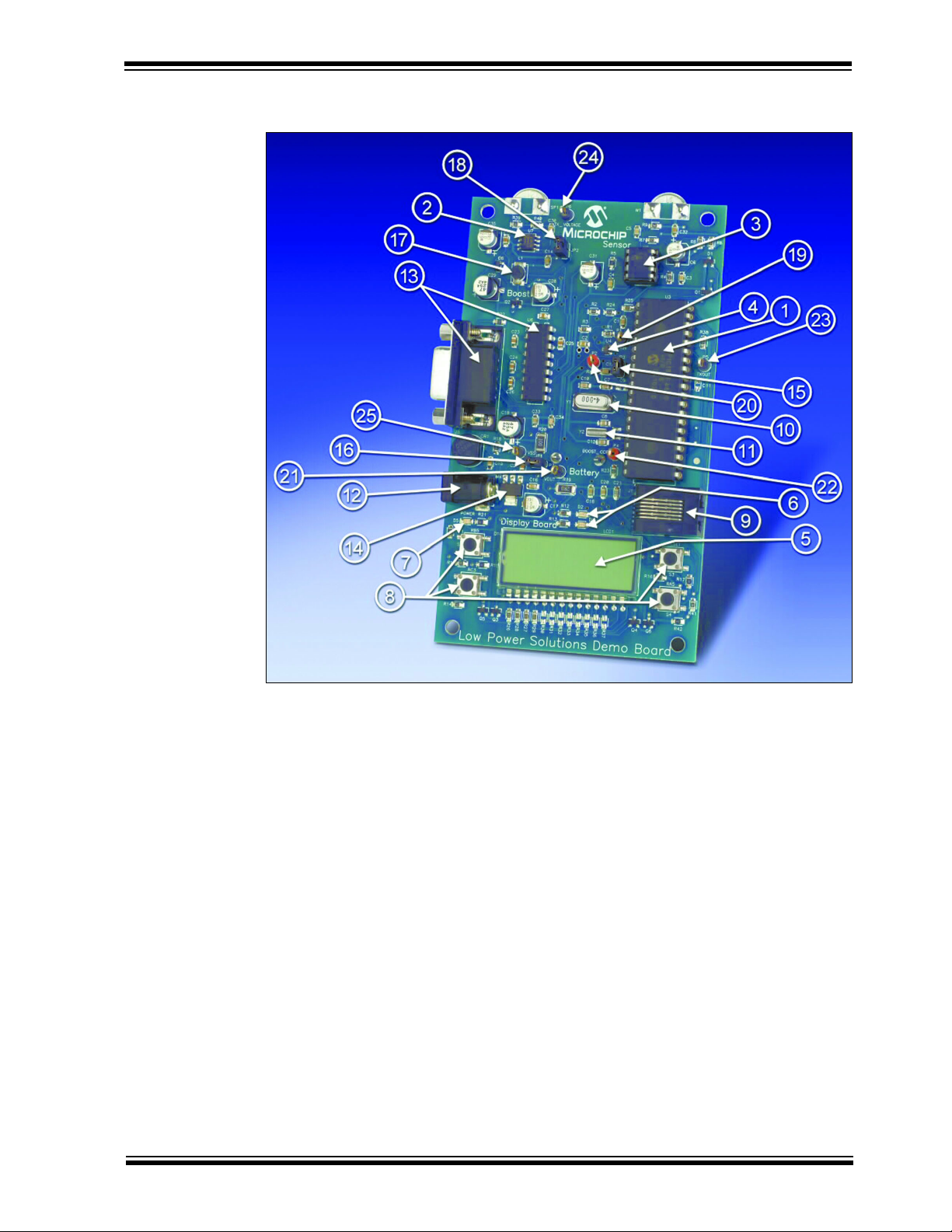
The Low Power Solutions demonstration board has the following hardware features:
1. PIC18F4620 featuring nanoWatt Technology
2. Ultrasonic transmitter featuring Microchip Technology TC1428 CMOS Driver
3. Ultrasonic receiver featuring Microchip Technology MCP6293 Op-amp
4. Microchip Technology TC1047A temperature sensor
5. Static LCD display
6. 2 LEDs connected to RA4 and RC5
7. Green power-on indicator LED
8. Four push button switches for external stimulus and Reset
9. MPLAB ICD 2 connector
10. 4MHz crystal connected to OSC1 and OSC2
11. 32KHz crystal for Timer1 clock operations
12. Power supply connector
13. RS-232 socket and associated hardware for direct connection to an RS-232
interface
14. On-board +5V regulator for direct input from 9V AC/DC wall adapter or 9V battery
15. Jumper JP3 to measure PICmicro current consumption with current meter
16. Jumper JP1 to measure system current consumption with current meter
17. 5V to 10V boost power supply
18. Jumper JP2 to disconnect boost power supply from ultrasonic transmitter
19. Receiver output test point
20. External reference test point
21. 5V test point
22. Boost PWM test point
23. Transmitter PWM test point
24. Boost output test point
SS test point
25. V
DS51512A-page 4 2003 Microchip Technology Inc.
Getting Started with MPLAB® IDE
FIGURE 1-1: LOW POWER SOLUTIONS DEMONSTRATION BOARD
HARDWARE
1.3 LOW POWER SOLUTIONS DEMONSTRATION BOARD DEFAULT DEMONSTRATION
The Low Power Solutions demonstration board is a functional, short distance range
finder. Once enabled, it repeatedly measures distance and updates the display. The
distance is displayed in centimeters on the LCD. It continues to run for approximately
one minute, pauses until SW1 is pressed, then restarts the process. The range finder
is capable of measuring up to 60 cm.
2003 Microchip Technology Inc. DS51512A-page 5

Workshop-in-a-Box 2: Low Power Solutions Demonstration Board User’s Guide
NOTES:
DS51512A-page 6 2003 Microchip Technology Inc.

2.1 INTRODUCTION
WORKSHOP-IN-A-BOX 2:
LOW POWER SOLUTIONS
DEMONSTRATION BOARD USER’S GUIDE
Chapter 2. Getting Started
The Low Power Solutions demonstration board may be used as a stand-alone board
with a preprogrammed device, with an MPLAB
ICD (In-Circuit Debugger) system. For a list of PICmicro
MPLAB ICE (In-Circuit Emulator) or MPLAB ICD (In-Circuit Debugger) systems, please
refer to the Development Systems Ordering Guide (DS30177).
®
ICE (In-Circuit Emulator) or MPLAB
®
microcontroller compatible
2.2 LOW POWER SOLUTIONS DEMONSTRATION BOARD AS A STAND-ALONE BOARD – PREPROGRAMMED DEVICE
The Low Power Solutions demonstration board features a PIC18F4620 preprogrammed with functional range finder software. It can be demonstrated by following the
steps listed below:
• Verify that jumpers JP1, JP2 and JP3 are closed (shorted).
• Apply power to the Low Power Solutions demonstration board. For information on
acceptable power sources, see Appendix A.
To reprogram the sample device, the following will be necessary:
1. Program source code. User source code may be used to program the device or,
if this has previously been done, the sample program may be restored from the
file on the included CD-ROM.
2. MPLAB C18 may be used to modify the source code and the hex file can be
programmed into the device. The demonstration and tutorial software are written
using Microchip Technology’s MPLAB C18 C compiler.
3. MPLAB ICD 2 (programmer functionality available with MPLAB IDE v6.00 or
greater) can be connected to the Low Power Solutions demonstration board.
Once the sample program is in hex file format, MPLAB ICD 2 may be used to
program the PIC18F4620 or similar device.
2.3 THE LOW POWER SOLUTIONS DEMONSTRATION BOARD USED WITH AN
IN-CIRCUIT EMULATOR OR IN-CIRCUIT DEBUGGER
To use Low Power Solutions demonstration board with an MPLAB ICE (In-Circuit
Emulator) or MPLAB ICD (In-Circuit Debugger) system, refer to the tool’s user guide
for instructions on how to power-up and configure the MPLAB ICE/MPLAB ICD, as well
as how to connect to target boards.
Note: The provided stand-offs can be configured to allow the demonstration
board to stand up vertically. Pass the threaded end of each post through a
hole in the board near the “Low Power Solutions Demo Board” label and
fasten another stand-off to the first.
2003 Microchip Technology Inc. DS51512A-page 7

Workshop-in-a-Box 2: Low Power Solutions Demonstration Board User’s Guide
NOTES:
DS51512A-page 8 2003 Microchip Technology Inc.

DEMONSTRATION BOARD USER’S GUIDE
Chapter 3. Demonstration Software
3.1 INTRODUCTION
The demonstration program is preprogrammed into the sample device,
(WIB2demo.hex). Also, this program is on the included CD-ROM program disk for user
reference, (i.e., if the sample device has been reprogrammed with another program,
the tutorial may be reprogrammed into the device).
For detailed information on the Low Power Solutions demonstration board hardware,
please refer to Appendix A.
3.2 TUTORIAL PROGRAM OPERATION
The provided demonstration program enables the Low Power Solutions demonstration
board to measure short distances using ultrasonic reflections (see Figure 3-1). This
program does not implement all system or PICmicro power management improvements. These improvements are left as an exercise for the user. Refer to the hands-on
write-up on the included CD for additional information on the exercises.
On power-up, the distance is repeatedly measured and the distance is displayed on the
LCD in centimeters. After approximately one minute, the process stops and waits for
SW1 to be pressed. After pressing SW1, the sequence restarts. The Low Power
Solutions demonstration board is capable of measuring distances up to 60 cm. The
distance is largely dependent on how hard, flat and large the reflected surface is.
WORKSHOP-IN-A-BOX 2:
LOW POWER SOLUTIONS
2003 Microchip Technology Inc. DS51512A-page 9

Workshop-in-a-Box 2: Low Power Solutions Demonstration Board User’s Guide
FIGURE 3-1: DEMONSTRATION PROGRAM STATE DIAGRAM
Start
No
No
Initialize system
Turn on LED
Enable Boost
Boost ready?
Xmit Pulses
Turn Timer on
Enable Rcvr
Enable Reference
Reflection
detected?
Turn Timer off
Read Timer
Disable Reference
Yes
Yes
No
Find median
Calc distance
Update LCD
150
measurements?
Turn off LCD
Switch S1
pressed?
No
Yes
Yes
No Yes
5 Samples
taken?
DS51512A-page 10 2003 Microchip Technology Inc.

Appendix A. Hardware Detail
A.1 INTRODUCTION
The Low Power Solutions Demo Board hardware is intended to illustrate the ease of
use of nanoWatt features of PIC18 MCUs. The Low Power Solutions Demo Board
features the following hardware elements:
A.1.1 Power Supply
There are two ways to supply power to the Low Power Solutions Demo Board:
• A 9V battery can be plugged into the connector on the back of the board.
• A 9V, 100 mA unregulated AC or DC supply can be plugged into J2.
A power supply can be purchased through Microchip, Part #AC162039. MPLAB ICD 2
users may use the MPLAB ICD to power the target board to 5V, up to 200 mA, if the
MPLAB ICD 2 is connected to the PC with a serial cable. The green LED (D5) will be
lit when power is applied.
WORKSHOP-IN-A-BOX 2:
LOW POWER SOLUTIONS
DEMONSTRATION BOARD USER’S GUIDE
A.1.2 RS-232 Serial Port
An RS-232 level shifting IC has been provided with all necessary hardware to support
connection of an RS-232 host through the DB9 connector. The port is configured as
DCE and can be connected to a PC using a straight-through cable.
The PIC18 RX and TX pins are tied to the RX and TX lines of the LT1280A. The driver
can be put into a low power state by outputting a logic level low on RC4.
A.1.3 Switches
Three switches provide the following functions:
• S1 – Active-low switch connected to RB5
• S2 – Active-low switch connected to RC3
• S3 – MCLR to hard reset the processor
• S4 – Active-low switch connected to RA5
When pressed, the switches are grounded. When Idle, they are pulled high (+5V).
A.1.4 Oscillator Options
• 4 MHz crystal for OSC1 and OSC2 supplied.
• 32.768 kHz (watch type) crystal for Timer1.
A.1.5 ICD Connector
By way of the modular connector (J1), the MPLAB ICD 2 can be connected for low-cost
debugging. The ICD connector utilizes RB6 and RB7 of the microcontroller for in-circuit
debugging.
A.1.6 Temperature Sensor
This is a serial digital thermal sensor (TC1047A) connected to RE2. The sensor
outputs an analog voltage representation of the temperature.
2003 Microchip Technology Inc. DS51512A-page 11

Workshop-in-a-Box 2: Low Power Solutions Demonstration Board User’s Guide
A.1.7 LCD
A 3-1/2 digit, seven segment LCD display displays the distance in centimeters. There
are eight segment lines (RD7:RD0) and four common lines (RB4, RB2:RB0). A
software algorithm generates the LCD waveforms. The board layout also supports four
seven segment LED modules if the LCD display is removed. The software to control
the LED display is not provided.
A.1.8 DC Boost Circuit
The boost generates a 10V output from a 5V source. The output voltage is modulated
and doubled using a CMOS Driver (TC1428), to produce a 20V, 40 KHz pulse
sequence for the ultrasonic transmitter.
A.1.9 Receiver
The ultrasonic receiver output is conditioned and amplified using an op-amp
(MCP6293) which features a pin selectable low-power mode. The low power mode is
enabled by outputting a logic level high on RE1.
A.1.10 Board Layout And Schematics
The following figures show the parts layout (silkscreen) and schematics for the Low
Power Solutions Demo Board.
DS51512A-page 12 2003 Microchip Technology Inc.

Hardware Detail
FIGURE A-1: LOW POWER SOLUTIONS DEMO BOARD PARTS LAYOUT
2003 Microchip Technology Inc. DS51512A-page 13

Workshop-in-a-Box 2: Low Power Solutions Demonstration Board User’s Guide
FIGURE A-2: LOW POWER SOLUTIONS DEMO BOARD SCHEMATIC-PAGE 1
DS51512A-page 14 2003 Microchip Technology Inc.

Hardware Detail
FIGURE A-3: LOW POWER SOLUTIONS DEMO BOARD SCHEMATIC-PAGE 2
2003 Microchip Technology Inc. DS51512A-page 15

Workshop-in-a-Box 2: Low Power Solutions Demonstration Board User’s Guide
FIGURE A-4: LOW POWER SOLUTIONS DEMO BOARD SCHEMATIC-PAGE 3
DS51512A-page 16 2003 Microchip Technology Inc.

Hardware Detail
FIGURE A-5: LOW POWER SOLUTIONS DEMO BOARD SCHEMATIC-PAGE 4
2003 Microchip Technology Inc. DS51512A-page 17

Workshop-in-a-Box 2: Low Power Solutions Demonstration Board User’s Guide
FIGURE A-6: LOW POWER SOLUTIONS DEMO BOARD SCHEMATIC-PAGE 5
DS51512A-page 18 2003 Microchip Technology Inc.

Hardware Detail
FIGURE A-7: LOW POWER SOLUTIONS DEMO BOARD SCHEMATIC-PAGE 6
2003 Microchip Technology Inc. DS51512A-page 19

Workshop-in-a-Box 2: Low Power Solutions Demonstration Board User’s Guide
FIGURE A-8: LOW POWER SOLUTIONS DEMO BOARD SCHEMATIC-PAGE 7
DS51512A-page 20 2003 Microchip Technology Inc.

NOTES:
Hardware Detail
2003 Microchip Technology Inc. DS51512A-page 21

WORLDWIDE SALES AND SERVICE
AMERICAS
Corporate Office
2355 West Chandler Blvd.
Chandler, AZ 85224-6199
Tel: 480-792-7200
Fax: 480-792-7277
Technical Support:
http:\\support.microchip.com
Web Address:
www.microchip.com
Atlanta
Alpharetta, GA
Tel: 770-640-0034
Fax: 770-640-0307
Boston
Westford, MA
Tel: 978-692-3848
Fax: 978-692-3821
Chicago
Itasca, IL
Tel: 630-285-0071
Fax: 630-285-0075
Dallas
Addison, TX
Tel: 972-818-7423
Fax: 972-818-2924
Detroit
Farmington Hills, MI
Tel: 248-538-2250
Fax: 248-538-2260
Kokomo
Kokomo, IN
Tel: 765-864-8360
Fax: 765-864-8387
Los Angeles
Mission Viejo, CA
Tel: 949-462-9523
Fax: 949-462-9608
San Jose
Mountain View, CA
Tel: 650-215-1444
Fax: 650-961-0286
Tor ont o
Mississauga, Ontario,
Canada
Tel: 905-673-0699
Fax: 905-673-6509
ASIA/PACIFIC
Australia - Sydney
Tel: 61-2-9868-6733
Fax: 61-2-9868-6755
China - Beijing
Tel: 86-10-8528-2100
Fax: 86-10-8528-2104
China - Chengdu
Tel: 86-28-8676-6200
Fax: 86-28-8676-6599
China - Fuzhou
Tel: 86-591-8750-3506
Fax: 86-591-8750-3521
China - Hong Kong SAR
Tel: 852-2401-1200
Fax: 852-2401-3431
China - Shanghai
Tel: 86-21-5407-5533
Fax: 86-21-5407-5066
China - Shenyang
Tel: 86-24-2334-2829
Fax: 86-24-2334-2393
China - Shenzhen
Tel: 86-755-8203-2660
Fax: 86-755-8203-1760
China - Shunde
Tel: 86-757-2839-5507
Fax: 86-757-2839-5571
China - Qingdao
Tel: 86-532-502-7355
Fax: 86-532-502-7205
ASIA/PACIFIC
India - Bangalore
Tel: 91-80-2229-0061
Fax: 91-80-2229-0062
India - New Delhi
Tel: 91-11-5160-8632
Fax: 91-11-5160-8632
Japan - Kanagawa
Tel: 81-45-471- 6166
Fax: 81-45-471-6122
Korea - Seoul
Tel: 82-2-554-7200
Fax: 82-2-558-5932 or
82-2-558-5934
Singapore
Tel: 65-6334-8870
Fax: 65-6334-8850
Taiwan - Kaohsiung
Tel: 886-7-536-4818
Fax: 886-7-536-4803
Taiwan - Taipei
Tel: 886-2-2500-6610
Fax: 886-2-2508-0102
Taiwan - Hsinchu
Tel: 886-3-572-9526
Fax: 886-3-572-6459
EUROPE
Austria - Weis
Tel: 43-7242-2244-399
Fax: 43-7242-2244-393
Denmark - Ballerup
Tel: 45-4420-9895
Fax: 45-4420-9910
France - Massy
Tel: 33-1-69-53-63-20
Fax: 33-1-69-30-90-79
Germany - Ismaning
Tel: 49-89-627-144-0
Fax: 49-89-627-144-44
Italy - Milan
Tel: 39-0331-742611
Fax: 39-0331-466781
Netherlands - Drunen
Tel: 31-416-690399
Fax: 31-416-690340
England - Berkshire
Tel: 44-118-921-5869
Fax: 44-118-921-5820
10/20/04
DS51512A-page 22 2004 Microchip Technology Inc.
 Loading...