

Page 1

UG0847
HiFive Unleashed Platform User Guide
Preliminary
October 2018
Page 2

HiFive Unleashed Platform User Guide
Contents
1 Revision History ............................................................................................................................. 1
1.1 Revision 1.0 ........................................................................................................................................ 1
2 Overview ........................................................................................................................................ 2
2.1 HiFive Unleashed Platform (MPFS-DEV-KIT) ....................................................................................... 2
3 Hardware Features ........................................................................................................................ 3
3.1 HiFive Unleashed Kit ........................................................................................................................... 3
4 System Setup and Prerequisites .................................................................................................... 6
4.1 Libero SoC PolarFire Design Suite ....................................................................................................... 6
4.2 Programming FlashPro and FlashPro Express .................................................................................... 6
4.3 Microsemi PolarFire Linux SDK for the HiFive Unleashed Expansion Board ...................................... 6
4.3.1 Ubuntu .................................................................................................................................................... 7
4.3.2 Centos ..................................................................................................................................................... 7
4.4 Firmware Versions .............................................................................................................................. 7
5 Board Setup ................................................................................................................................... 8
6 Software Installation and Configuration ...................................................................................... 12
6.1 Programming the FPGA Using FlashPro ............................................................................................ 12
6.2 Building and Loading the Linux Image .............................................................................................. 14
6.2.1 Preparing an SD Card and Programming an Image for the First Time .................................................. 14
6.2.2 Rebuilding the Linux Kernel ................................................................................................................... 15
6.2.3 Linux Boot and Login Credentials .......................................................................................................... 16
7 FPGA Design in Libero .................................................................................................................. 17
7.1 Memory Map .................................................................................................................................... 17
7.2 GPIO Implementation ....................................................................................................................... 18
8 Reference ..................................................................................................................................... 19
8.1 Recommended Reading ................................................................................................................... 19
8.2 Reference ......................................................................................................................................... 19
9 Technical Support ........................................................................................................................ 20
Microsemi Proprietary and Confidential. UG0847 Revision 1.0
Page 3

HiFive Unleashed Platform User Guide
1 Revision History
The revision history describes the changes that were implemented in the document. The changes are
listed by revision, starting with the most current publication.
1.1 Revision 1.0
Revision 1.0 is the first publication of this document.
Microsemi Proprietary and Confidential. UG0847 Revision 1.0 1
Page 4

HiFive Unleashed Platform User Guide
2 Overview
The HiFive Unleashed Platform™ is purpose-built to emulate most of the functionality of the upcoming
PolarFire SoC FPGA, which will be the industry’s first RISC-V based FPGA SoC.
This guide describes the MPFS-DEV-KIT, board setup, and installation steps to get the HiFive Unleashed
platform boot Linux. New IP cores can be ported on the PolarFire FPGA with the Libero SoC PolarFire
Design Suite. For more details on the design suite, see section .FPGA Design in Libero (see page 17)
2.1 HiFive Unleashed Platform (MPFS-DEV-KIT)
The HiFive Unleashed Platform consists of the SiFive’s HiFive Unleashed kit and Microsemi’s HiFive
Unleashed Expansion kit with their respective accessories. Microsemi's HiFive Unleashed Expansion
board enables users to create a Linux system running on a RISC-V core complex, with a large FPGA fabric
accessible through the memory map. The expansion board is shipped with a pre-configured bitstream
enabling PCIe root port functionality.
HiFive Unleashed Kit
One SiFive's HiFive Unleashed board
One power wall adapter 12 V
One USB-A to micro USB-B cable
HiFive Unleashed Expansion Kit
One Microsemi's HiFive Unleashed Expansion Board
One USB-A to micro USB-B cable
One 12 V, AC power adapter and cord
One FlashPro4/FlashPro5 programming dongle
Two Libero Platinum software licenses of duration one year ($995 value)
Microsemi Proprietary and Confidential. UG0847 Revision 1.0 2
Page 5
HiFive Unleashed Platform User Guide
3 Hardware Features
This section provides the block diagram and features of the kit hardware.
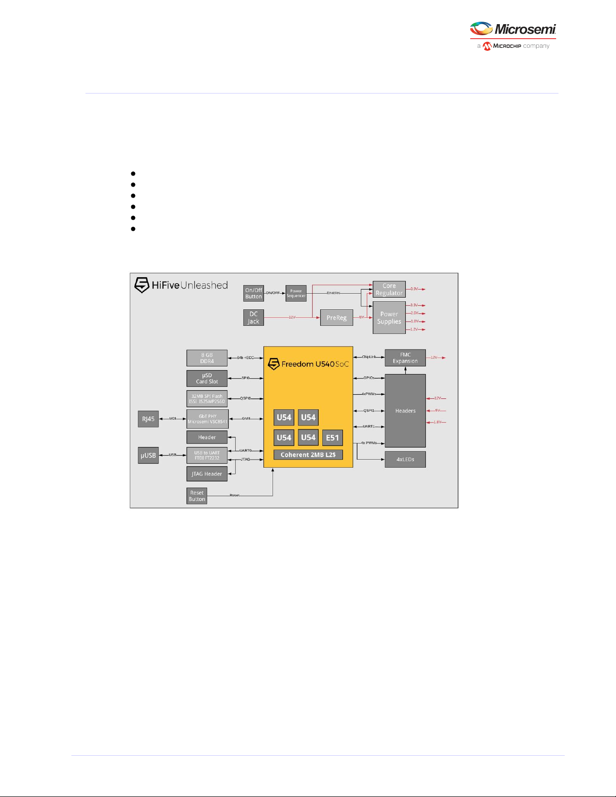
3.1 HiFive Unleashed Kit
SiFive’s HiFive Unleashed development kit is based on the Freedom U540-C000 chip, the first 4+1 multicore RISC-V Linux-capable SoC.
SiFive Freedom U540 SoC
8 GB DDR4 with ECC
Gigabit Ethernet port
32 MB quad SPI flash from ISSI
MicroSD card for removable storage
FMC connector for future expansion
Figure 1 • HiFive Unleashed Board Block Diagram
Microsemi Proprietary and Confidential. UG0847 Revision 1.0 3
Page 6
HiFive Unleashed Platform User Guide
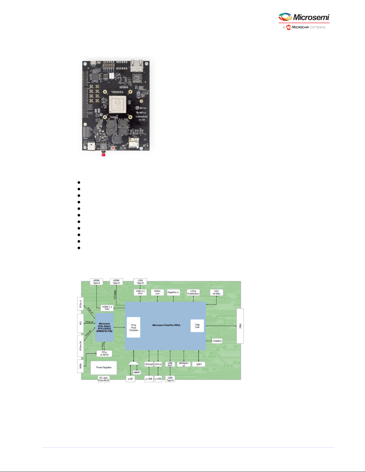
Figure 2 • HiFive Unleashed Board
The HiFive Unleashed Expansion board contains the following items.
300K LE PolarFire FPGA in an FCG1152 package (MPF300TS-1FCG1152EES)
24-lane PCIe switch
eMMC Nand Flash, uSD card slot
USB to Uart bridges
4 Gbit DDR4 x16
PCI Express x1 card connector
PCI Express x16 card connector with x4 lane support
SPI Flash for FPGA remote updates, QSPI Flash connected to GPIO
FMC connection to HFU540-4A00 kit
SSD M.2 connector
SATA connector
Figure 3 • HiFive Unleashed Expansion Board Block Diagram
Microsemi Proprietary and Confidential. UG0847 Revision 1.0 4
Page 7
HiFive Unleashed Platform User Guide
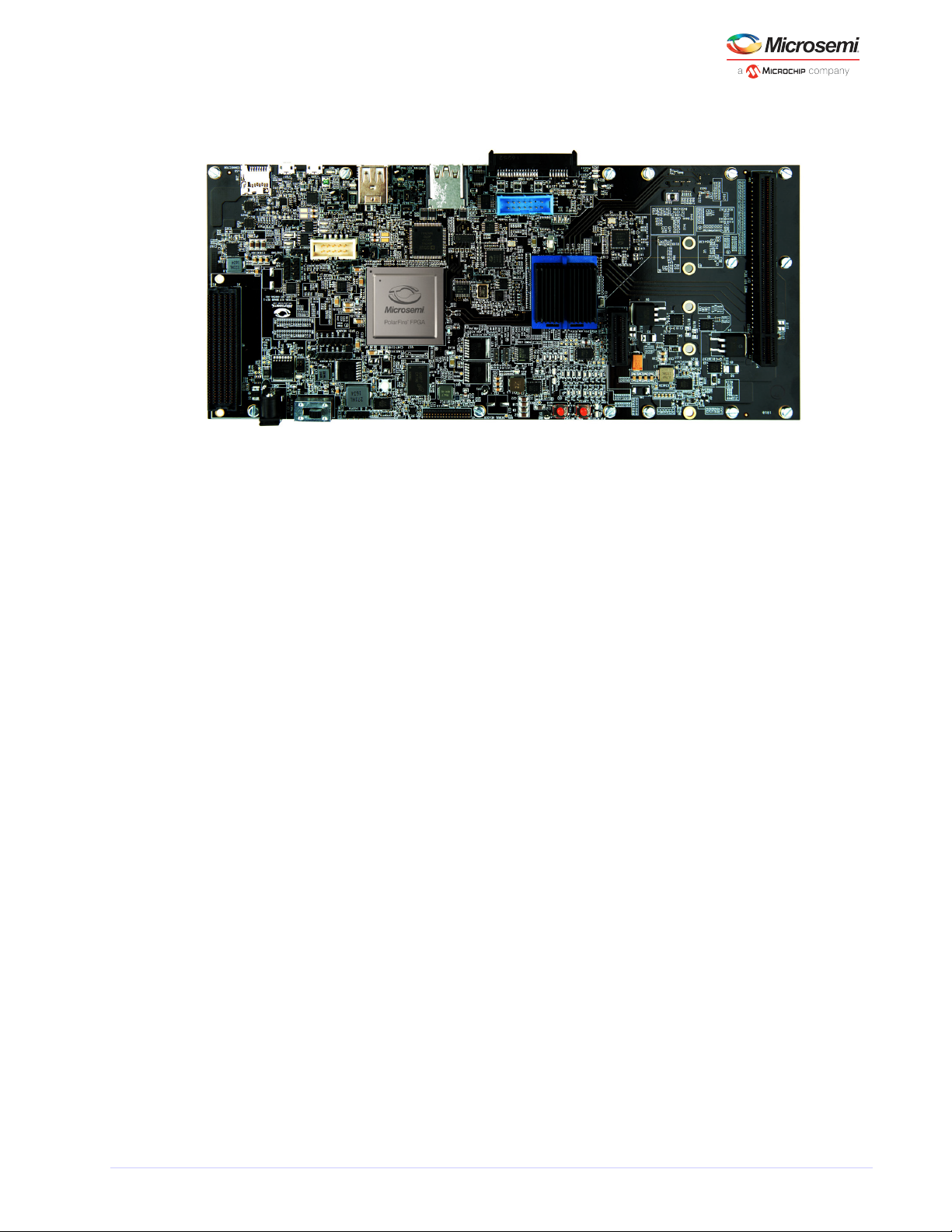
Figure 4 • HiFive Unleashed Expansion Board
Microsemi Proprietary and Confidential. UG0847 Revision 1.0 5
Page 8

HiFive Unleashed Platform User Guide
4 System Setup and Prerequisites
Download and install the following development tools in the PC in order to design, synthesize, simulate,
and debug on the HiFive Unleashed Platform (MPFS-DEV-KIT).
4.1 Libero SoC PolarFire Design Suite
The Libero SoC PolarFire Design Suite offers high productivity with its comprehensive, easy-to-learn,
easy-to-adopt development tools for designing with Microsemi's . The suite PolarFire FPGA Family
integrates industry standard Synopsys ® synthesis and Mentor Graphics Synplify Pro ME ModelSim ME
simulation with best-in-class constraints management, capabilities, and Debug Tools Secure Production
support.Programming
Download Libero SoC PolarFire v2.2 for Windows environment .here
Download Libero SoC PolarFire v2.2 for Linux environment .here
Along with the purchase of the MPFS-DEV-KIT, customers are eligible for two Platinum Floating licenses
for the Libero SoC PolarFire Design Suite. Write to with the mi-v-embeddedpartner@microchip.com
subject “License Request <your organization name>” and include the 12-digit MAC ID of the two linux
machines/PCs in your email.
4.2 Programming FlashPro and FlashPro Express
The Microsemi FlashPro programming system is a combination of Microsemi's FlashPro software and a
hardware programmer. Together, they provide in-system programming (ISP) for all FPGA families. The
required programming and debug software is integrated with the Libero SoC PolarFire software. This
software is also available as a standalone programmer for production programming. Visit Microsemi's
page to download the standalone programmer (if needed).FlashPro
Table 1 • FlashPro Software and Hardware Support
Software Description Hardware Description
FP Express Software for Windows and Linux FlashPro5 Hardware programmer for Windows and Linux
FlashPro Software for Windows FlashPro4 Hardware programmer for Windows
4.3 Microsemi PolarFire Linux SDK for the HiFive Unleashed Expansion Board
The Microsemi PolarFire Linux SDK is based on the SiFive freedom-u-sdk with modifications to the
device tree to support the HiFive Unleashed Expansion board. It also includes drivers for Microsemi
PCIe, I C, SPI, MMUART, and GPIO peripherals. See to download the
2
Firmware Versions (see page 7)
Microsemi PolarFire Linux SDK.
The build procedure follows that of the freedom-u-sdk as described in HiFive Unleashed Getting Started
.Guide
Before building the Linux image, the following packages must be installed depending on the Linux
distribution in your machine.
Microsemi Proprietary and Confidential. UG0847 Revision 1.0 6
Page 9

HiFive Unleashed Platform User Guide
4.3.1 Ubuntu
(tested on Ubuntu 16.04)
apt-get update
sudo apt-get install autoconf automake autotools-dev bc bison build-essential curl
flex gawk gdisk git gperf libgmp-dev libmpc-dev libmpfr-dev libncurses-dev libssl-dev
libtool patchutils python screen texinfo unzip zlib1g-dev patch device-tree-compiler
openssl-devel wget
4.3.2 Centos
(tested on Centos7)
yum update
sudo yum install autoconf automake autotools-dev bc bison build-essential gcc-c++
curl flex gawk gdisk git gperf gmp-devel libmpc-dev libmpfr-dev ncurses-devel libssldev libtool patchutils python screen texinfo unzip zlib1g-dev zlib-devel patch dtc
openssl-devel wget vim-common
4.4 Firmware Versions
The following table contains links to the Libero Project, .stp file, .job file, and the Linux SDK for each
release.
Table 2 • Software Versions Links
Revision Libero Project .stp .job MPFS-Linux-SDK
Initial
release
Libero Initial Release .stp Initial Release .job Initial Release MPFS-Linux-SDK
For more documentation, visit the .extranet page
Microsemi Proprietary and Confidential. UG0847 Revision 1.0 7
Page 10

HiFive Unleashed Platform User Guide
1.
2.
5 Board Setup
Follow the instructions to set up the HiFive Unleashed board.
Switch off the power button (red button in the following figure) on the HiFive Unleashed board.
Ensure the fan is plugged in.
Figure 5 • Power Button and Fan Connection
Set all pins in the DIP-switch block to the LEFT. The ON position=0; therefore, this sets MSEL to
mode 1111. See the boot modes table in Section 4 of the for HiFive Unleashed Getting Started Guide
more information on MSEL.
Figure 6 • DIP-Switch Setting
Microsemi Proprietary and Confidential. UG0847 Revision 1.0 8
Page 11

HiFive Unleashed Platform User Guide
3.
4.
5.
6.
7.
Insert an SD-card programmed with the bootloader and Linux. See the Building the Linux Image (see
section of this document for details on creating the content of this SD card.page 14)
Figure 7 • SD Card
If available, connect the board to a network switch. The board will run DHCP on boot and start an
ssh server. The MAC address is 70:b3:d5:92:fX:XX, where X:XX is replaced by the board number
converted to hexadecimal. For example, if the board is H5U-00063, then the last digits of the MAC
address are 0:3f.
Figure 8 • Ethernet
Connect the board through USB to a developer machine. The USB connector has two serial
interfaces: the first contains the Linux console running at 115200 baud and the second provides
JTAG suitable for use with OpenOCD.
On the HiFive Unleashed Expansion board, update the PolarFire FPGA with the FPGA bitstream
provided. See section for steps to program Software Installation and Configuration (see page 12)
the FPGA.
The HiFive Unleashed platform is now configured as seen in section 7 (FPGA Design in Libero) (see
.page 17)
Microsemi Proprietary and Confidential. UG0847 Revision 1.0 9
Page 12

HiFive Unleashed Platform User Guide
8.
9.
10.
Plug-in the HiFive Unleashed board to the HiFive Unleashed Expansion board on the FMC connector.
Push the power button ON on the HiFive Unleashed board.
Note: Do not connect the power supply to the HiFive Unleashed board.
Figure 9 • Power Button
Connect the power supply to the HiFive Unleashed Expansion board in order to power the HiFive
Unleashed board.
Slide the HiFive Unleashed Expansion board’s power switch (SW3) on. Boot messages should now
appear on the console in the developer's machine.
Figure 10 • Power Connections
Microsemi Proprietary and Confidential. UG0847 Revision 1.0 10
Page 13

HiFive Unleashed Platform User Guide
11. After 30 seconds, an LED should begin to regularly blink a heartbeat on the HiFive Unleashed board.
Figure 11 • LED Indicators
Microsemi Proprietary and Confidential. UG0847 Revision 1.0 11
Page 14

HiFive Unleashed Platform User Guide
1.
2.
3.
4.
5.
6.
7.
8.
9.
10.
11.
12.
1.
2.
3.
4.
5.
6.
7.
8.
9.
10.
6 Software Installation and Configuration
The following steps explain the procedure to download the FPGA bitstream onto the PolarFire FPGA.
6.1 Programming the FPGA Using FlashPro
Windows Environment
To program the PolarFire device with the .stp programming file (using FlashPro in Windows
environment), perform the following steps. The link to the .stp file is given in Firmware Versions (see
.page 7)
Ensure that the jumper settings on the board are the same as those listed in Jumper Settings (see
.page 13)
Note: The power supply switch must be switched off while making the jumper connections.
Connect the power supply cable to the J3 connector on the board.
Connect the FlashPro4 to a PC USB port and to the connector J24 (FP4 header) of the HiFive
Unleashed Expansion board.
Power on the board using the SW3 slide switch.
On the host PC, launch the FlashPro software.
Click to create a new project. In the New Project window, enter a project name.New Project
Click and navigate to the location where you want to save the project.Browse
Select as the programming mode and click to save the project.Single Device OK
Click .Configure Device
Click , and navigate to the location where the HFU540_EXP_Bitstream_r20101.stp file is Browse
located and select the file.
Click . The required programming file is selected and ready to be programmed in the device.Open
Click to program the device. When the device is programmed successfully, a Run PASSED PROGRAM
status is displayed.
See the for more information.FlashPro User Guide
Linux Environment
To program the PolarFire device with the .job programming file (using FlashPro5 programmer in Linux
environment), perform the following steps. The link to the .job file can be found in Firmware Versions
.(see page 7)
Ensure that the jumper settings on the board are the same as those listed in Jumper Settings (see
.page 13)
The power supply switch must be switched off while making the jumper connections.Note:
Connect the power supply cable to the J3 connector on the board.
Connect the FlashPro5 to a PC USB port and to the connector J24 (FP4 header) of the HiFive
Unleashed Expansion board.
Power on the board using the SW3 slide switch.
On the host PC, launch the FlashPro Express (FP Express) software.
From the Project menu, choose from Programming Job.Create Job Project
Click to load the Programming Job File HFU540_EXP_Bitstream_r20102.job, and specify your Browse
FlashPro Express job project location. Click to continue.OK
Save the FlashPro Express job project.
Set the Programming Action in the dropdown menu to PROGRAM.
Click . Detailed individual programmer and device status information appears in the RUN
Programmer List. Your programmer status (PASSED or FAILED) appears in the Programmer Status
Bar.
See the for more information.FlashPro Express User Guide
Microsemi Proprietary and Confidential. UG0847 Revision 1.0 12
Page 15

HiFive Unleashed Platform User Guide
Table 3 • HiFive Unleashed Expansion Board Jumper Settings
Switch Ref Section Description Definition Default
1 SW3 Power switch Sliding switch
for 12 V input
Open: DC adaptor 12 V is
not connected to the board
power
Close: DC adaptor 12 V is
connected to board power
supplies
Open
2 SW5 PCIe switch
(Switchtec)
Selection of
Normal/Boot
Recovery
mode for PCIe
switch
0: Boot recovery mode
1: Normal mode
1–2: Normal
mode
3 J25 SATA
controller
Between SPI
flash output to
input of PCIe
to SATA
controller
Open: SPI flash o/p is not
connected to PCIe to SATA
controller
Close: SPI flash o/p is
connected to PCIe to SATA
controller
Close
5 J31 USB instance 1 VBUS source
selection (onboard 5 V/USB
connector)
Open: VBUS sourced by USB
connector (Device mode)
Close: On-board 5 V to USB
CONN (Host mode)
Close
6 J27 USB instance 2 Configuring
USB PHY (U60)
as host/device
Open: USB3340 acts as
device
Close: USB3340 acts as host
Close
7 J30 USB instance 2 VBUS source
selection (onboard 5 V/USB
connector)
Open: VBUS sourced by USB
connector (Device mode)
Close: On-board 5 V to USB
CONN (Host mode)
Close
8 J21 SC-SPI SC-SPI I/O
configuration
interface
Open: SC SPI acts as master
Close: SC SPI acts as slave
Close
9 J22 JTAG Weak pull
down to JTAG
TRSTB
Open: 1K pull down
connected to TRSTB
Close: 1K||100K pull down
connected to TRSTB
Open
Microsemi Proprietary and Confidential. UG0847 Revision 1.0 13
Page 16

HiFive Unleashed Platform User Guide
Switch Ref Section Description Definition Default
11 J4 FMC bank IO
voltage
FMC VADJ
voltage
selection
1–2: VADJ is set to 3.3 V
3–4: VADJ is set to 2.5 V
5–6: VADJ is set to 1.8 V
7–8: VADJ is set to 1.5 V
9–10: VADJ is set to 1.2 V
5–6: VADJ is
set to 1.8 V
6.2 Building and Loading the Linux Image
To build and checkout the code, use the following set of commands.
$ tar -zxvf mpfs-linux-sdk-20180906.tar.gz
$ cd mpfs-linux-sdk
$ unset RISCV
$ make all
This will build the system to a work/sub-directory.
Note: It can take awhile to build the first time.
The first time the build is run, it also builds the RISC-V cross compiler toolchain. The output file work/bbl.
bin contains the bootloader (RISC-V pk/bbl), the Linux kernel, and the device tree blob.
6.2.1 Preparing an SD Card and Programming an Image for the First Time
Add an SD card to boot your system (16 GB or 32 GB).
If the SD card is auto-mounted, first unmount it manually. Check if your SD card is mounted and
unmount it using the following commands, where XN are replaced with the SD card’s specific values
found from the mount command:
$ mount | grep sd
$ sudo umount /dev/sdXN
The SD card should have a GUID Partition Table (GPT) rather than Master Boot Record (MBR). It must
also have the following partitions on it:
The first partition should be for the kernel image. It will be 32 MB in size.
The second partition is reserved for a Linux root partition. It will fill most of the free space on the
card.
The third partition should be for the HiFive First Stage Boot Loader (FSBL) binary. It will be 1 MB in
size.
To automatically partition and format your SD card, in the top level of mpfs-linux-sdk, type:
$ sudo make DISK=/dev/path-to-sdcard-device format-boot-loader
This populates the SD card with the required partition types, and it copies across the Linux kernel image
to the appropriate partition. If an fsbl.bin file is present in the top-level directory, it copies this across to
the correct partition.
This command may fail with slower USB SD card devices but succeed if repeated.should
Microsemi Proprietary and Confidential. UG0847 Revision 1.0 14
Page 17

HiFive Unleashed Platform User Guide
At this point, your system should be bootable using your new SD card. You can remove it from your PC
and insert it into the SD card slot on the HiFive Unleashed board, and then power-on the HiFive
Unleashed Expansion board.
6.2.2 Rebuilding the Linux Kernel
To rebuild your kernel, type the following from the top level of mpfs-linux-sdk:
$ rm work/linux/vmlinux
$ make
Copy this newly built image to the SD card using:
$ sudo dd if=work/bbl.bin of=/dev/path-to-sdcard-device1
Note the ‘1’ at the end of the SD Card device path to signify the first partition.
The source for the device tree for HiFive Unleashed Expansion board is in the conf/riscvpc.dts directory.
The configuration options used for the Linux kernel are in conf/linux_defconfig.
Currently, the Microsemi PolarFire Linux SDK for the HiFive Unleashed platform uses a modification to
the RISC-V Bootloader startup code to pass in the device tree blob (see riscv-pk/machine/mentry.S for
the modification.)
Microsemi Proprietary and Confidential. UG0847 Revision 1.0 15
Page 18

HiFive Unleashed Platform User Guide
6.2.3 Linux Boot and Login Credentials
The Linux boot process can be observed by connecting a serial terminal to the USB port on the HiFive
Unleashed board. Settings are 115200 baud, 8 data bits, 1 stop bit, no parity, and no flow control.
The root password is “microchip”. The console should look similar to the following figure.
Figure 12 • Console Image for Boot
Microsemi Proprietary and Confidential. UG0847 Revision 1.0 16
Page 19

HiFive Unleashed Platform User Guide
7 FPGA Design in Libero
Libero SoC Design suite provides a comprehensive design flow including traditional FPGA design flow,
embedded design flow, and graphical configurators. The suite provides a comprehensive development
environment to build embedded solutions using hard core and soft core processors.
The FPGA design has provision to interface the PolarFire FPGA (in the HiFive Unleashed Expansion
board) with the HiFive Unleashed board using the ChipLink interface. The FPGA fabric is instantiated
with the ChipLink to AXI bridge, while peripherals—GPIO, MMUART, SPI, and I C—are connected to it
2
using the CoreAXIInterconnect, AXI to AHB, AHBLite, and CoreAPB IPs. The PolarFire PCIe AXI Slave is
connected to the AXI2CL2AXI bridge through CoreAXIInterconnect. One AXI port is exposed and marked
as unused and can connect to user logic.
The ChipLink interface uses 125 MHz clock and AXI interface uses 75 MHz clock.
The high-level block diagram for the Libero project implemented on the PolarFire FPGA is as seen in the
following figure.
Figure 13 • Libero Project Block Diagram
More IPs are being ported on the HiFive Unleashed Platform and will be made available on request.
7.1 Memory Map
The IPs ported on the PolarFire FPGA are accessible from the RISC-V U540 memory map as listed in the
following table. The interrupt number 42 is used for all the peripherals.
Table 4 • Memory Map
Peripherals Mem
Requirement
Start Address End Address Mem Allocation Comments
PCIe
PCIe Config
Space
256 MB 0x2030000000 0x203fffffff 256 MB
PCIe Mem
Space 32
512 MB 0x0040000000 0x005fffffff 512 MB
PCIe Mem
Space 64
2 GB 0x2080000000 0x20ffffffff 2048 MB
Microsemi Proprietary and Confidential. UG0847 Revision 1.0 17
Page 20

HiFive Unleashed Platform User Guide
Peripherals Mem
Requirement
Start Address End Address Mem Allocation Comments
PCIe APB
Space
1 MB 0x2000000000 0x20000fffff 1 MB
Peripherals
I2C_0 4 KB 0x2000100000 0x2000100fff 4095 KB I2C0 header
Reserved 4 KB 0x2000101000 0x2000101fff 4095 KB Reserved
GPIO 4 KB 0x2000103000 0x2000103fff 4095 KB GPIO Implementation
(see page 18)
MMUART_0 4 KB 0x2000104000 0x2000104fff 4095 KB J36
Reserved 4 KB 0x2000105000 0x2000105fff 4095 KB Reserved
Reserved 4 KB 0x2000106000 0x2000106fff 4095 KB Reserved
SPI 0 4 KB 0x2000107000 0x2000107fff 4095 KB SPI0 header
Reserved 4 KB 0x2000108000 0x2000108fff 4095 KB Reserved
FIC (AXI) 256 MB 0x2010000000 0x201fffffff 256 MB To connect with user
logic
free space 0x2020000000 0x202fffffff 256 MB
7.2 GPIO Implementation
The GPIO implemented in the design is pinned out as a starting point for your custom design
implementation. The details of the GPIO pinout is listed in the following table.
Table 5 • GPIO Pinout
GPIO Function
0 led4
1 led5
2 J2-pin13
3 J2-pin14
4 sw9
5 sw10
6 J2-pin9
7 USB1 reset
Microsemi Proprietary and Confidential. UG0847 Revision 1.0 18
Page 21

HiFive Unleashed Platform User Guide
8 Reference
Visit the following links for further reference reading materials.
8.1 Recommended Reading
RISC-V User-level ISA Specification
RISC-V Draft Privileged ISA Specification
SiFive FU540-C000 User Manual
TU0844 Libero SoC PolarFire v2.2 Design Flow Tutorial
HiFive Unleashed Getting Started Guide
8.2 Reference
PolarFire FPGA Documentation
Libero SoC PolarFire Documentation
FlashPro User Guide for PolarFire
FlashPro Express User Guide for PolarFire
Microsemi Proprietary and Confidential. UG0847 Revision 1.0 19
Page 22

HiFive Unleashed Platform User Guide
9 Technical Support
For technical queries, email . Microsemi’s technical support mi-v-embeddedpartner@microchip.com
team will create a ticket, address the query, and track it to completion.
Microsemi Proprietary and Confidential. UG0847 Revision 1.0 20
Page 23

HiFive Unleashed Platform User Guide
Microsemi Headquarters
One Enterprise, Aliso Viejo,
CA 92656 USA
Within the USA: +1 (800) 713-4113
Outside the USA: +1 (949) 380-6100
Sales: +1 (949) 380-6136
Fax: +1 (949) 215-4996
Email: sales.support@microsemi.com
www.microsemi.com
© 2018 Microsemi. All rights reserved. Microsemi and the Microsemi logo
are trademarks of Microsemi Corporation. All other trademarks and service
marks are the property of their respective owners.
Microsemi makes no warranty, representation, or guarantee regarding the information contained herein or the suitability of its products and s ervices
for any particular purpose, nor does Microsemi assume a ny liability whatsoever arising out of the app lication or use of any product or circuit. The
products sold hereunder and an y other products sold by Microsemi have been s ubject to limited testing and should not be us ed in conjunction with
mission-critical equipment or applications. Any performance specifications are believed to be reliable but are not verified, and Buyer must condu ct and
complete all performance and other testing of the products, alone and together with, or installed in , any end-products. Buyer shall not rely on any data
and per formance specifications or para meters provided by Microsemi. It is the Buyer's responsibility to ind ependently determine suitability of any
products and to test and verify the same. The information provided by Microsemi hereunder is provided "as is, where is" and with all faults, and the
entire risk associated with such information is entirely with the Buyer. Microsemi does not grant, explicitly or implicitly, to any party any patent rights,
licenses, or any other IP rights, whether with regard to such information itself or anything described by such information. Information provided in this
document is proprietar y to Microsemi, and Micr osemi reserves the right to make any changes to the information in this document or to any products
and services at any time without notice.
Microsemi, a wholly owned subsidi ary of Microchip Technology Inc. (Nasdaq: MCHP), offers a comprehensive portfolio of semiconductor and system
solutions for aerospace & defense, communications, data center and industrial markets. Products include high-performance and radiation-hardened
analog m ixed-signal integrated circuits, FPG As, SoCs and ASICs; power management products; timing and synchronization devices and p recise time
solutions, setting the world's standard for time; voice processing devices; RF solutions; discrete components; enterprise storage and communica tion
solutions; security technologies and scalable anti-tamper products; Etherne t solutions; Power-over-Ethernet ICs and midspans; as well as custom design
capabilities and services. Microsemi i s headquartered in Aliso Viejo, California, and has approxim ately 4,800 employees globally. Learn more at www.
microsemi.com.
50200847
Microsemi Proprietary and Confidential. UG0847 Revision 1.0 21
 Loading...