

Page 1

TC1303A/TC1303B/
TC1303C/TC1304
500 mA Synchronous Buck Regulator,
+ 300 mA LDO with Power-Good Output
Features
• Dual-Output Regulator (500 mA Buck Regulator
and 300 mA Low-Dropout Regulator)
• Power-Good Output with 300ms Delay
• Total Device Quiescent Curre nt = 65 µA, Typ.
• Independent Shutdown for Buck and LDO
Outputs (TC1303)
• Both Outputs Internally Compensated
• Synchronous Buck Regulator:
- Over 90% Typical Efficiency
- 2.0 MHz Fixed-Frequency PWM
(Heavy Loa d)
- Low Output Noise
- Automatic PWM to PFM mode transition
- Adjustable (0.8V to 4.5V) and Standard
Fixed-Output Voltages (0.8V, 1.2V, 1.5V,
1.8V, 2.5V, 3.3V)
• Low-Dropout Regulator:
- Low-Dropout Vol t ag e= 137mV Typ. @
200 mA
- Standard Fixed-Output Voltages
(1.5V, 1.8V, 2.5V, 3.3V)
• Power-Good Function:
- Monitors Buck Output Function (TC1303A)
- Monitors LDO Output Function (TC1303B)
- Monitors Both Buck and LDO Output Func-
tions (TC1303C and TC1304)
- 300 ms Delay Used for Processor Reset
• Sequenced Startup and Shutdown (TC1304)
• Small 10-pin 3X3 DFN or MSOP Package
Options
• Operating Junction Temperature Range:
- -40°C to +125°C
• Undervoltage Lockout (UVLO)
• Output Short Circuit Protection
• Overtemperature Protection
Description
The TC1303/TC1304 combines a 500 mA synchronous buck regulator and 300m A Low-Drop out Regulator (LDO) with a power-good monitor to provide a highly
integrated solution for devices that require multiple
supply voltages. The unique combination of an
integrated buck switching regulator and low-dropout
linear regulator provides the lowest system cost for
dual-output voltage applications that require one lower
processor core voltage and one higher bias voltage.
The 500 mA synchronous buck regul ator swit ches at a
fixed frequency of 2.0 MHz when the load is heavy,
providing a low noise, small-size solution. When the
load on the buck output is reduced to light levels, it
changes operation to a Pulse Frequency Modulation
(PFM) mode to minimize quie scent current draw from
the battery. No intervention is necessary for smooth
transition from one mode to another.
The LDO provides a 300 mA auxiliary output that
requires a single 1 µF ceramic output capacitor,
minimizing board area and cost. The typical dropout
voltage for the LDO output is 137 mV for a 200 mA
load.
For the TC1303/TC1304, the power-good output is
based on the regulation of the buck regulator output, the
LDO output or the combination of both. The TC1304
features start-up and shutdown output sequencing.
The TC1303/TC1304 i s available in either the 10-pin
DFN or MSOP package.
Additional protection features include: UVLO,
overtemperature and overcurrent protection on both
outputs.
For a complete listing of TC1303/TC1304 standard
parts, consult your Microchip representative.
Applications
• Cellular Phones
• Portable Computers
• USB-Powered Devices
• Handheld Medical Instruments
• Organizers and PDAs
© 2005 Microchip Technology Inc. DS21949B-page 1
Page 2
TC1303A/TC1303B/TC1303C/TC1304
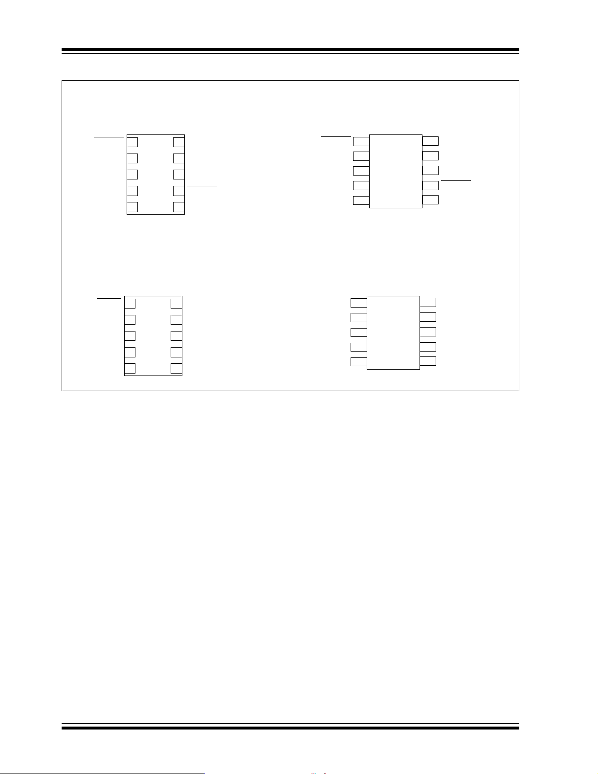
Package Types
TC1303A,B,C
SHDN2
V
IN2
V
OUT2
PG
A
GND
SHDN
V
IN2
V
OUT2
PG
A
GND
10-Lead DFN
1
2
3
4
5
10
9
8
7
6
10-Lead DFN
1
2
3
4
5
10
9
8
7
6
P
GND
L
X
V
IN1
SHDN1
V
FB1/VOUT1
P
GND
L
X
V
IN1
A
GND
V
FB1/VOUT1
TC1304
SHDN2
V
IN2
V
OUT2
PG
A
GND
SHDN
V
IN2
V
OUT2
PG
A
GND
10-Lead MSOP
1
2
3
4
5
10-Lead MSOP
1
2
3
4
5
10
9
8
7
6
10
9
8
7
6
P
GND
L
X
V
IN1
SHDN1
V
FB1/VOUT1
P
GND
L
X
V
IN1
A
GND
V
FB1/VOUT1
DS21949B-page 2 © 2005 Microchip Technology Inc.
Page 3
TC1303A/TC1303B/TC1303C/TC1304
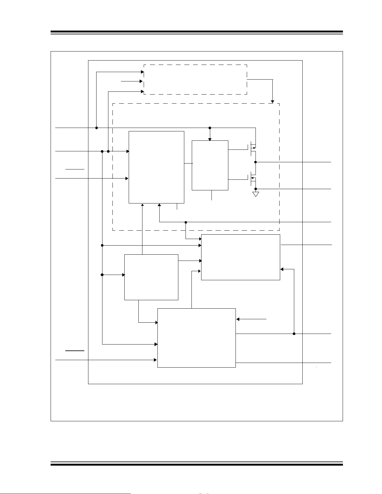
Functional Block Diagram – TC1303
V
IN1
V
IN2
SHDN1
V
REF
Undervoltage Lockout
(UVLO)
UVLO
Synchronous Buck Regulator
PDRV
L
X
Control
A
GND
Driver
NDRV
P
GND
Sense Switcher for A,C
TC1303A
(1),B(2),C(1)
P
GND
options
P
GND
V
OUT1/VFB1
PG
PG Generator with Delay
V
REF
SHDN2
Note 1: PG open-drain for A,C options
2: PG push-pull output for B option
Sense LDO for B,C
LDO
UVLO
V
A
OUT2
GND
© 2005 Microchip Technology Inc. DS21949B-page 3
Page 4
TC1303A/TC1303B/TC1303C/TC1304
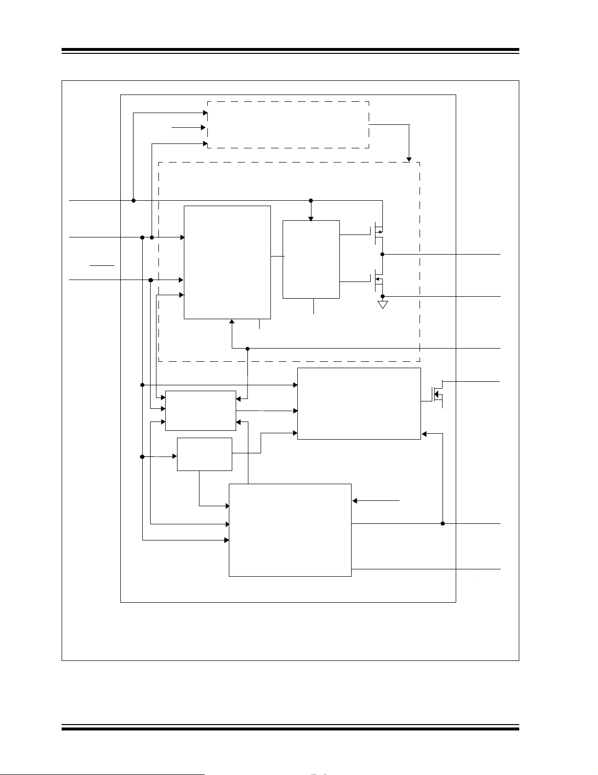
Functional Block Diagram – TC1304
V
IN1
V
IN2
SHDN
V
REF
Control
Output Voltage
Sequencer ckt.
Undervoltage Lockout
(UVLO)
Synchronous Buck Regulator
Driver
P
GND
A
GND
TC1304
PG Generator with Delay
PDRV
NDRV
(Note)
UVLO
P
GND
A
GND
L
X
P
GND
V
OUT1/VFB1
PG
V
REF
Note: PG open-drain for TC1304
LDO
UVLO
V
A
OUT2
GND
DS21949B-page 4 © 2005 Microchip Technology Inc.
Page 5
TC1303A/TC1303B/TC1303C/TC1304
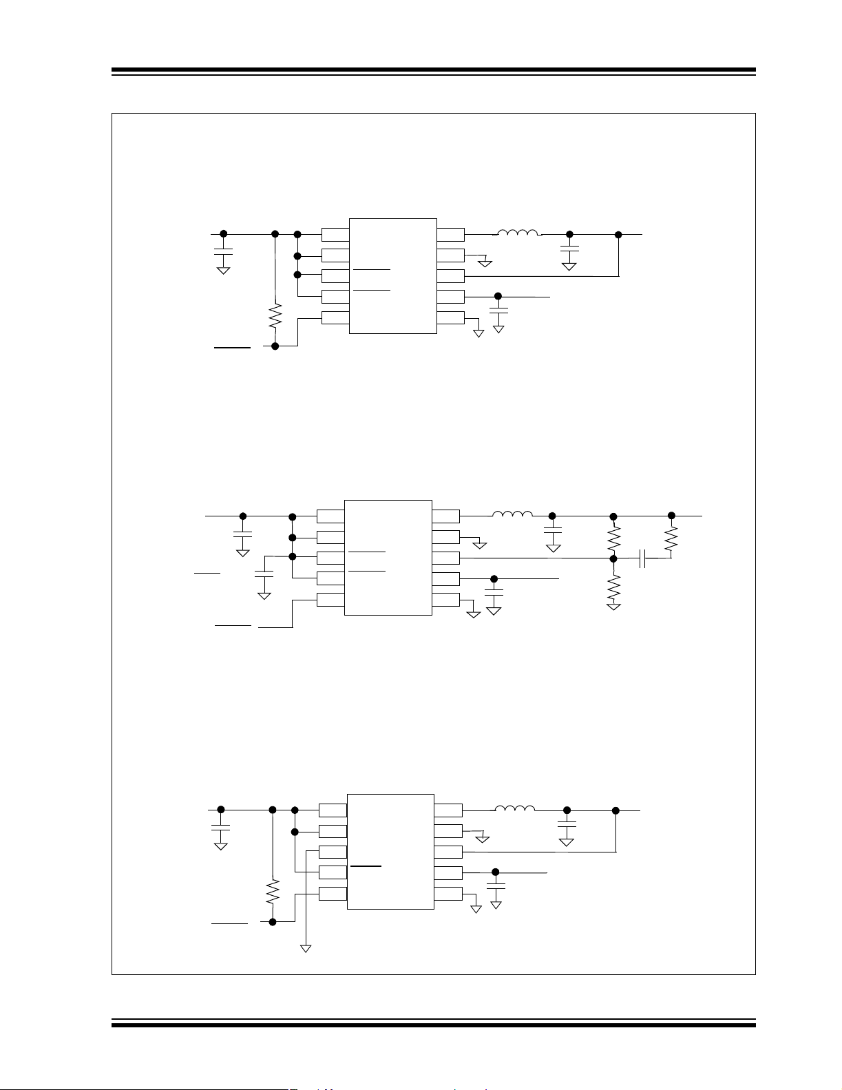
Typical Application Circuits
V
IN
2.7V to 4.2V
4.7 µF
R
PULLUP
Processor
RESET
TC1303A
Fixed-Output Application
10-Lead MS OP
8
2
7
1
V
IN1
V
IN2
SHDN1
PG
P
V
V
A
L
GND
OUT1
OUT2
GND
9
X
10
6
3SHDN2
54
TC1303B
Adjustable-Output Application
10-Lead DFN
4.7 µH
4.7 µF
1µF
V
OUT2
2.5V @ 300 mA
V
OUT1
1.5V @ 500 mA
4.5V to 5.5V
*Optional
Capacitor
V
IN2
2.7V to 4.2V
Input
Voltage
V
IN
1.0 µF
Processor
RESET
4.7 µF
R
PULLUP
Processor
RESET
4.7 µF
8
2
7
1
V
IN1
V
IN2
SHDN1
SHDN2
PG
V
V
P
GND
OUT1
OUT2
A
GND
9
L
X
10
6
3
54
(Note)
Note: Connect DFN package exposed pad to A
TC1304
Fixed-Output Application
10-Lead MSOP
V
8
IN1
V
2
IN2
A
7
GND
1
PG
P
V
V
A
GND
OUT1
OUT2
GND
L
9
X
10
6
3SHDN
54
4.7 µH
4.7 µF
1µF
4.7 µH
1µF
V
OUT2
3.3V @
300 mA
GND
4.7 µF
V
OUT2
2.5V @ 300 mA
200 kΩ 4.99 kΩ
33 pF
121 kΩ
.
V
OUT1
1.2V @ 500 mA
V
OUT1
2.1V @
500 mA
© 2005 Microchip Technology Inc. DS21949B-page 5
Page 6
TC1303A/TC1303B/TC1303C/TC1304
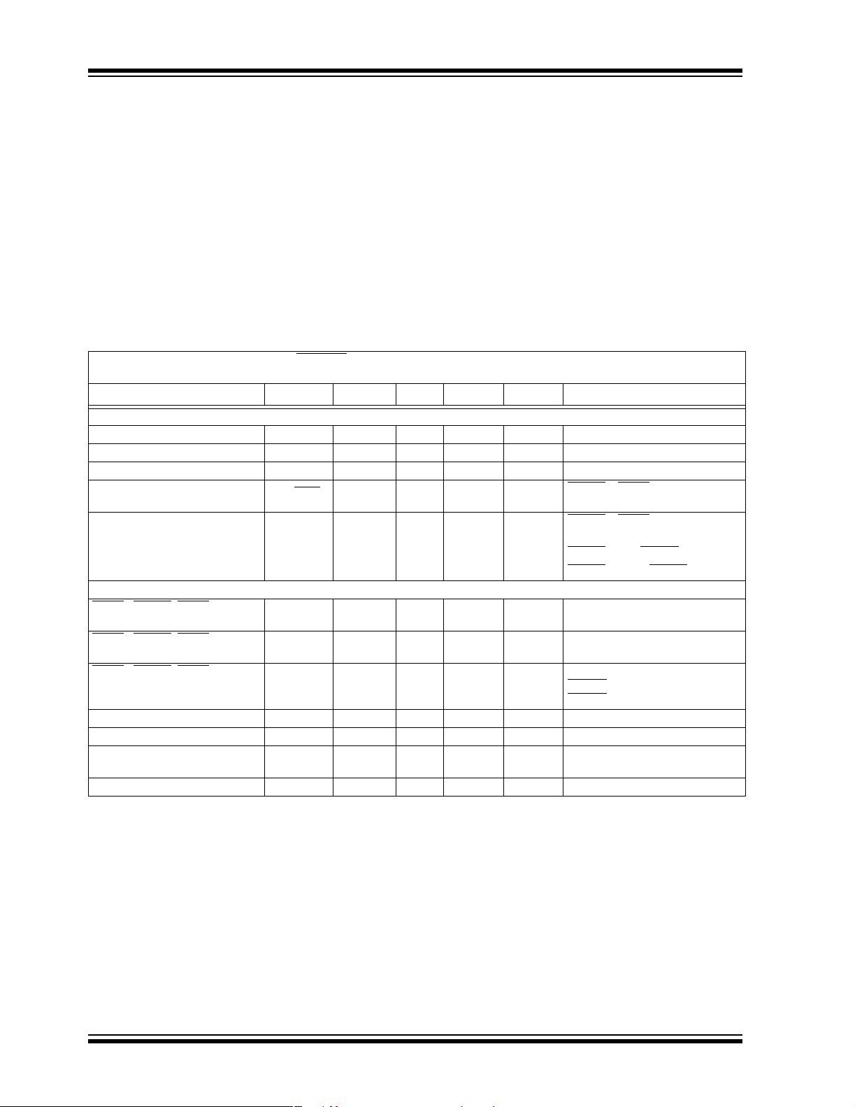
1.0 ELECTRICAL CHARACTERISTICS
† Notice: Stresses above those listed under “Maximum
Ratings” may cause permanent damage to the device. This is
a stress rating only and functional operation of the device at
those or any other conditions above those indicated in the
Absolute Maximum Ratings †
operational listings of this specification is not implied.
Exposure to maximum rating conditions fo r ext ended pe riods
V
- A
IN
All Other I/O .......................... .... (A
L
to P
X
P
GND
Output Short Circuit Current .................................Continuous
......................................................................6.0V
GND
........................ ...................... -0.3V to (V
GND
to A
...................................................-0.3V to +0.3V
GND
- 0.3V) to (V
GND
+ 0.3V)
IN
+ 0.3V)
IN
may affect device reliability.
Power Dissipation (Note 7) ..........................Internally Limited
Storage temperature.................................... .-65°C to +150°C
Ambient Temp. with Power Applied.................-40°C to +85°C
Operating Junction Tempe rature...................- 40°C to +125°C
ESD protection on all pins (HBM) ....................................... 3kV
DC CHARACTERISTICS
Electrical Characteristics: V
= 100 ma, I
I
OUT1
OUT2
IN1=VIN2
= 0.1 mA TA= +25°C. Boldface specifications apply over the TA range of -40°C to +85°C.
Parameters Sym Min Typ Max Units Conditions
Input/Output Characteristics
Input Voltage V
Maximum Output Current I
Maximum Output Current I
Shutdown Current
Combined V
IN1
and V
TC1303A,B Operating I
TC1303C, TC1304 Operating I
Synchronous Buck I
LDO I
Q
Current
IN2
Q
Q
Shutdown/UVLO/Thermal Shutdown Characteristics
SHDN
1,SHDN2, SHDN (TC1304)
Logic Input Voltage Low
SHDN
1,SHDN2, SHDN (TC1304)
Logic Input Voltage High
1,SHDN2, SHDN (TC1304)
SHDN
Input Leakage Current
Thermal Shutdown T
Thermal Shutdown Hysteresis T
Undervoltage Lockout
(V
OUT1
and V
OUT2
)
Undervoltage Lockout Hysteresis UVLO
Note 1: The Minimum V
2: V
3: TCV
is the regulator output voltage setting.
RX
OUT2
has to meet two conditions: VIN ≥ 2.7V and VIN ≥ VRX + V
IN
= ((V
OUT2max
4: Regulation is measured at a constant junction temperature using low duty-cycle pulse testing. Load regulation is tested
over a load range from 0.1 mA to the maximum specified output current.
5: Dropout voltage is defined as the input-to-output voltage differential at which the output voltage drops 2% below its
nominal value measured at a 1V differential.
6: The maximum allowable power dissipation is a function of ambient temperature, the maximum allowable junction
temperature and the thermal resistance from junction to air. (i.e. T
dissipation causes the device to initiate thermal shutdown.
7: The integrated MOSFET switches have an integral diode from the L
these diodes are forward-biased, the package power dissipation limits must be adhered to. Thermal protection is not
able to limit the junction temperature for these cases.
8: V
IN1
and V
are supplied by the same input source.
IN2
= SHDN1,2 =3.6V, C
IN
OUT1_MAX
OUT2_MAX
I
IN_SHDN
I
Q
Q
I
Q
OUT1=CIN
2.7 — 5.5 V Note 1, Note 2, Note 8
500 —— mANote 1
300 —— mANote 1
— 0.05 1 µA SHDN1 = SHDN2=GND
— 65.0
70.1
= 4 .7 µF, C
110
110
OUT2
— 38 — µA SHDN1 = VIN, SHDN2 = GND
— 46 — µA SHDN1 = GND, SHDN2 = V
V
IL
V
IH
I
IN
SHD
SHD-HYS
——15 %V
45 ——%VINV
-1.0 ±0.01 1.0 µA V
— 165 — °C Note 6, Note 7
—10— °C
UVLO 2.4 2.55 2.7 VV
– V
-
HYS
OUT2min
— 200 — mV
) * 106)/(V
OUT2
* DT).
, TJ, θJA). Exceeding the maximum allowable power
A
pin to VIN, and from LX to P
X
=1µF, L =4.7µH, V
OUT1
µA SHDN1 = SHDN2=V
I
=0mA, I
OUT1
V
IN
IN1=VIN2
IN1=VIN2
IN1=VIN2
SHDNX
SHDN
IN1
DROPOUT, VRX
Y =V
Falling
= VR1 or VR2.
OUT2
= 2.7V to 5.5V
= 2.7V to 5.5V
= 2.7V to 5.5V
=GND
IN
. In cases where
GND
(ADJ) = 1.8V,
IN2
=0mA
IN2
DS21949B-page 6 © 2005 Microchip Technology Inc.
Page 7
TC1303A/TC1303B/TC1303C/TC1304
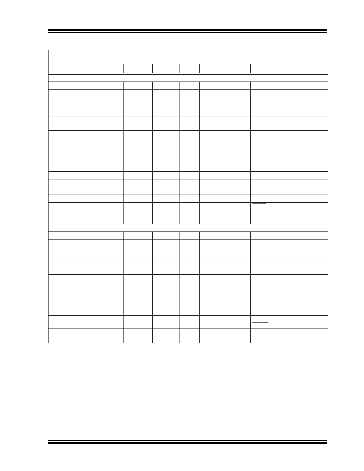
DC CHARACTERISTICS (CONTINUED)
Electrical Characteristics: V
= 100 ma, I
I
OUT1
OUT2
IN1=VIN2
= 0.1 mA TA= +25°C. Boldface specifications apply over the TA range of -40°C to +85°C.
Parameters Sym Min Typ Max Units Conditions
Synchronous Buck Regulator (V
Adjustable Output Voltage Range V
Adjustable Reference Feedback
Voltage (V
FB1
)
Feedback Input Bias Current
)
(I
FB1
Output Voltage Tolerance Fixed
(V
)
OUT1
Line Regulation (V
Load Regulation (V
Dropout Voltage V
)V
OUT1
)V
OUT1
OUT1
Internal Oscillator Frequency F
Sta rt Up T ime T
R
P-Channel R
DSon
N-Channel R
R
DSon
Pin Leakage Current I
L
X
Positive Current Limit Threshold +I
LDO Output (V
Output Voltage Tolerance (V
OUT2
)
OUT2
Temperature Coefficient TCV
Line Regulation ΔV
Load Regulation, V
Load Regulation, V
Dropout Voltage V
≥ 2.5V ΔV
OUT2
< 2.5V ΔV
OUT2
> 2.5V VIN – V
OUT2
Power Supply Rejection Ratio PSRR — 62 — dB f ≤ 100 Hz, I
Output Noise eN — 1.8 — µV/(Hz)
Output Short Circuit Current
(Average)
Note 1: The Minimum V
2: V
3: TCV
is the regulator output voltage setting.
RX
OUT2
has to meet two conditions: VIN ≥ 2.7V and VIN ≥ VRX + V
IN
= ((V
OUT2max
4: Regulation is measured at a constant junction temperature using low duty-cycle pulse testing. Load regulation is tested
over a load range from 0.1 mA to the maximum specified output current.
5: Dropout voltage is defined as the input-to-output voltage differential at which the output voltage drops 2% below its
nominal value measured at a 1V differential.
6: The maximum allowable power dissipation is a function of ambient temperature, the maximum allowable junction
temperature and the thermal resistance from junction to air. (i.e. T
dissipation causes the device to initiate thermal shutdown.
7: The integrated MOSFET switches have an integral diode from the L
these diodes are forward-biased, the package power dissipation limits must be adhered to. Thermal protection is not
able to limit the junction temperature for these cases.
8: V
IN1
and V
are supplied by the same input source.
IN2
= SHDN1,2 =3.6V, C
)
OUT1
OUT1
V
FB1
I
VFB1
V
OUT1
LINE-REG
LOAD-REG
VIN – V
OUT1
OSC
SS
DSon-P
DSon-N
LX
LX(MAX)
)V
OUT2
OUT
/
OUT2
ΔV
IN
/
OUT2
I
OUT2
/
OUT2
I
OUT2
OUT2
I
OUTsc2
– V
OUT2min
OUT1=CIN
= 4 .7 µF, C
=1µF, L =4.7µH, V
OUT2
OUT1
0.8 — 4.5 V
0.78 0.8 0.82 V
— -1.5 — nA
-2.5 ±0.3 +2.5 % Note 2
—0.2— %/VV
—0.2— %V
=VR+1V to 5.5V,
IN
= 100 mA
I
LOAD
+1.5V, I
IN=VR
500 mA (Note 1)
— 280 — mV I
= 500 mA, V
OUT1
(Note 5)
1.6 2.0 2.4 MHz
—0.5— msT
= 10% to 90%
R
— 450 650 mΩ IP=100 mA
— 450 650 mΩ IN=100 mA
-1.0 ±0.01 1.0 μA SHDN = 0V, VIN = 5.5V, LX = 0V,
L
= 5.5V
X
— 700 — mA
-2.5 ±0.3 +2.5 % Note 2
— 25 — ppm/°C Note 3
-0.2 ±0.02 +0.2 %/V (VR+1V) ≤ VIN ≤ 5.5V
-0.75 -0.08 +0.75 %I
-0.9 -0.18 +0.9 %I
— 137
205
300
500
mV I
— 240 — mA R
DROPOUT, VRX
) * 106)/(V
OUT2
* DT).
, TJ, θJA). Exceeding the maximum allowable power
A
pin to VIN, and from LX to P
X
½
= 0.1 mA to 300 mA (Note 4)
OUT2
= 0.1 mA to 300 mA (Note 4)
OUT2
= 200 mA (Note 5)
OUT2
I
= 300 mA
OUT2
= I
OUT2
=GND
≤ 1Ω
OUT1
=50mA,
= 0 µF
C
IN
f ≤ 1 kHz, I
SHDN1
LOAD2
= VR1 or VR2.
. In cases where
GND
(ADJ) = 1.8V,
= 100 mA to
LOAD
=3.3V
OUT1
= 50 mA,
OUT2
© 2005 Microchip Technology Inc. DS21949B-page 7
Page 8
TC1303A/TC1303B/TC1303C/TC1304
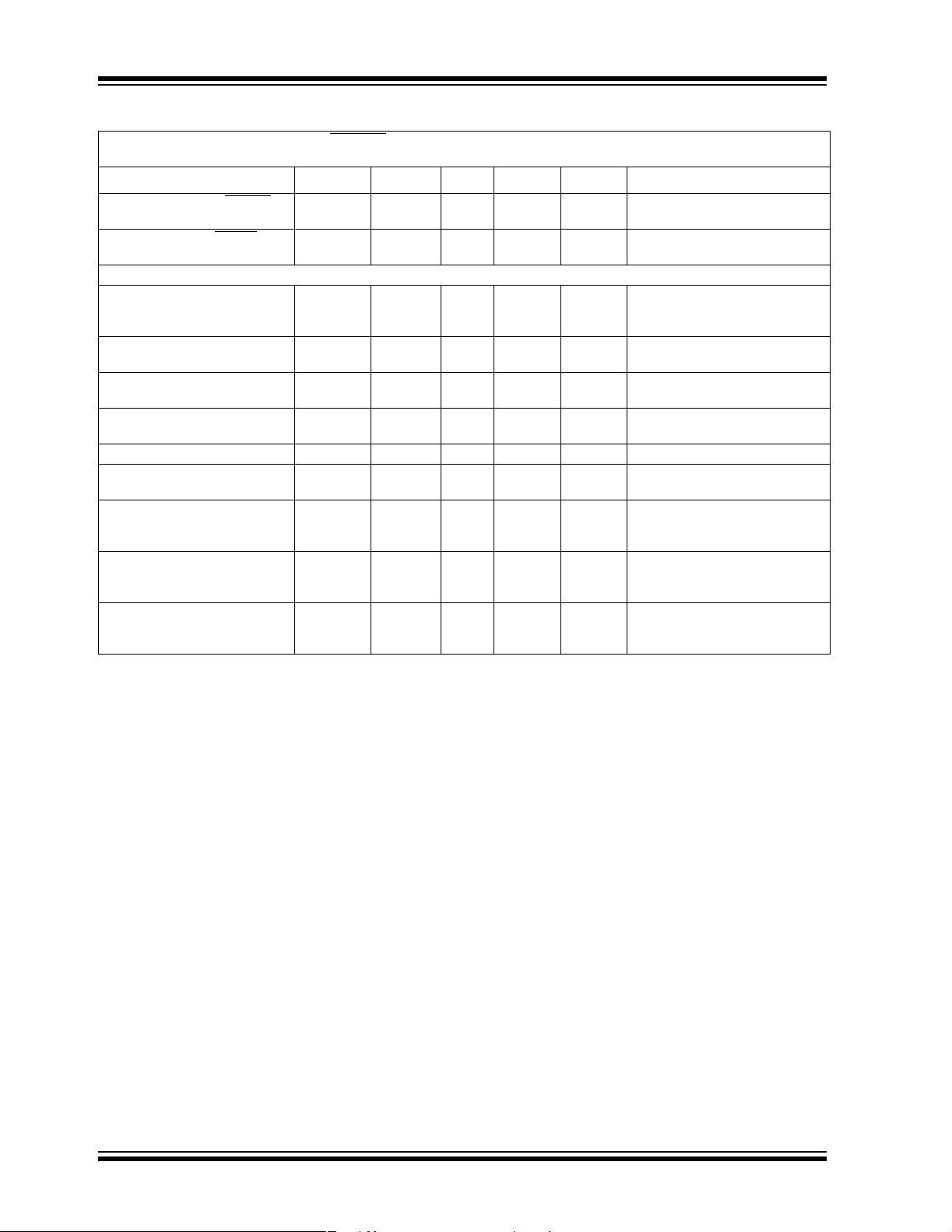
DC CHARACTERISTICS (CONTINUED)
Electrical Characteristics: V
= 100 ma, I
I
OUT1
OUT2
IN1=VIN2
= 0.1 mA TA= +25°C. Boldface specifications apply over the TA range of -40°C to +85°C.
Parameters Sym Min Typ Max Units Conditions
Wake-Up Time (From SHDN2
mode), (V
Settling Time (From SHDN2
mode), (V
OUT2
OUT2
)
)
Power-Good (PG)
Voltage Range PG V
PG Threshold High
(V
OUT1
or V
OUT2
)
PG Threshold Low
(V
OUT1
or V
OUT2
)
PG Threshold Hysteresis
(V
OUT1
and V
OUT2
)
PG Threshold Tempco ΔVTH/ΔT — 30 — ppm/° C
PG Delay t
PG Active Time-out Period t
PG Output Voltage Low PG_V
PG Output Voltage High
(TC1303B only)
Note 1: The Minimum V
2: V
3: TCV
is the regulator output voltage setting.
RX
OUT2
has to meet two conditions: VIN ≥ 2.7V and VIN ≥ VRX + V
IN
= ((V
OUT2max
4: Regulation is measured at a constant junction temperature using low duty-cycle pulse testing. Load regulation is tested
over a load range from 0.1 mA to the maximum specified output current.
5: Dropout voltage is defined as the input-to-output voltage differential at which the output voltage drops 2% below its
nominal value measured at a 1V differential.
6: The maximum allowable power dissipation is a function of ambient temperature, the maximum allowable junction
temperature and the thermal resistance from junction to air. (i.e. T
dissipation causes the device to initiate thermal shutdown.
7: The integrated MOSFET switches have an integral diode from the L
these diodes are forward-biased, the package power dissipation limits must be adhered to. Thermal protection is not
able to limit the junction temperature for these cases.
8: V
IN1
and V
are supplied by the same input source.
IN2
= SHDN1,2 =3.6V, C
t
WK
t
S
PG
V
TH_H
V
TH_L
V
TH_HYS
RPD
RPU
OL
OH
) * 106)/(V
0.9* V
– V
PG_V
OUT2min
OUT1=CIN
= 4 .7 µF, C
— 31 100 µs I
— 100 — µs I
1.0
1.2
—5.5
5.5
—9496 % of
89 92 — % of
—2—% of
— 165 — µs V
=1µF, L =4.7µH, V
OUT2
OUT1
OUT1
VTA = 0°C to +70°C
= -40°C to +85°C
T
A
V
≤ 2.7 I
IN
On Rising V
V
OUTX
V
OUTX=VOUT1
On Falling V
V
V
OUTX
OUTX
V
OUTX=VOUT1
V
OUTX=VOUT1
OUT1
to (V
140 262 560 ms V
——0.2 VV
OUT2
—— VV
DROPOUT, VRX
* DT).
OUT2
, TJ, θJA). Exceeding the maximum allowable power
A
pin to VIN, and from LX to P
X
OUT1
to V
I
SINK
OUT1
IPG= 1.2 mA V
I
= 100 µA, 1.0V < V
PG
OUT1
V
OUT2
V
OUT2
OUT1
= I
= 50 mA
OUT2
= I
= 50 mA
OUT2
= 100 µA
SINK
OUT1
or V
OUT1
or V
or V
or V
- 100 mV)
TH
or V
TH +
OUT2
OUT2=VTH
100 mV,
=(V
= 1.2 mA
or V
OUT2=VTH
IN2
or V
OUT2=VTH
≥ 1.8V, IPG= - 500 µA
< 1.8V,IPG= - 300 µA
= VR1 or VR2.
. In cases where
GND
(ADJ) = 1.8V,
or V
OUT2
OUT2
or V
OUT2
OUT2
OUT2
+ 100 mV)
TH
- 100 mV
-100mV
>2.7V
< 2.7V
IN2
+ 100 mV
,
DS21949B-page 8 © 2005 Microchip Technology Inc.
Page 9
TC1303A/TC1303B/TC1303C/TC1304
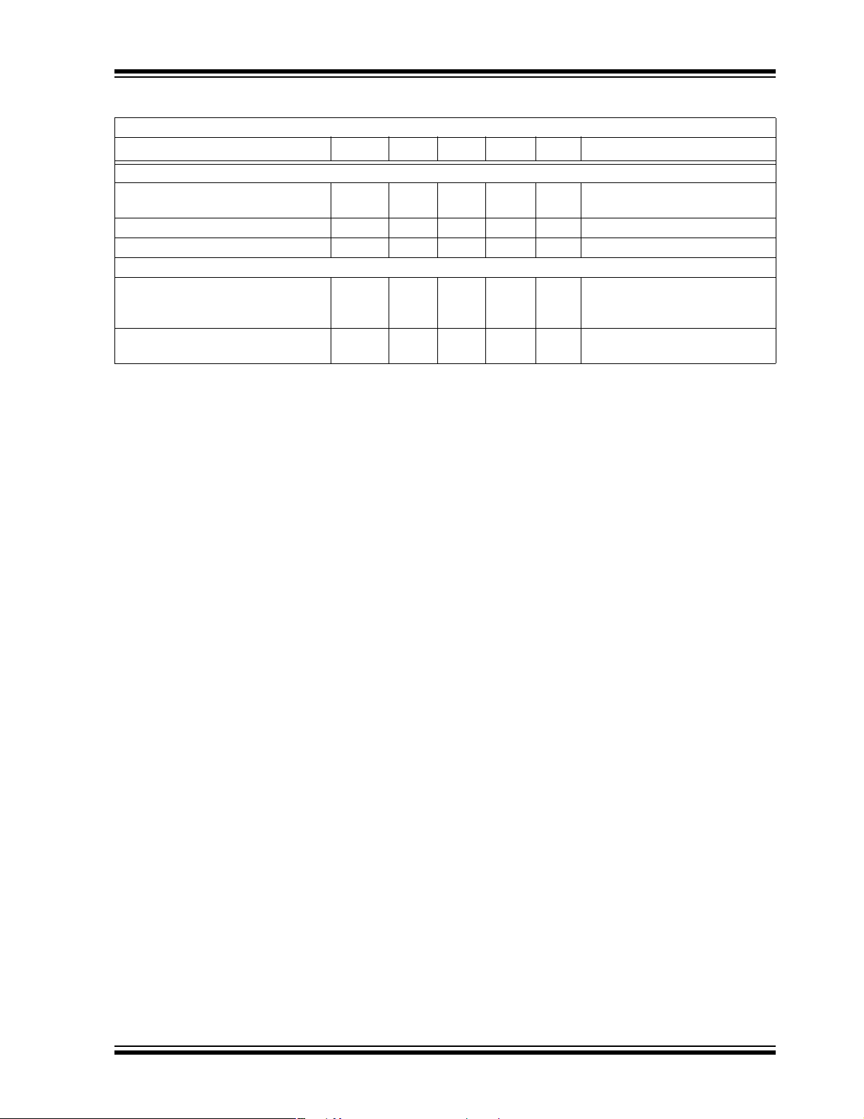
TEMPERATURE SPECIFICATIONS
Electrical Specifications: Unless otherwise indicated, all limits are specified for: VIN = +2.7V to +5.5V
Parameters Sym Min Typ Max Units Conditions
Temperature Ranges
Operating Junction Temperature
Range
Storage Temperature Range T
Maximum Junction Temperature T
Thermal Package Resistances
Thermal Resistance, 10L-DFN θ
Thermal Resistance, 10L-MSOP θ
T
J
A
J
JA
JA
-40 — +125 °C Steady state
-65 — +150 °C
— — +150 °C Transient
— 41 — °C/W Typical 4-layer Board with
Internal Ground Plane and 2 Vias
in Thermal Pad
— 113 — °C/W Typical 4-layer Board with
Internal Ground Plane
© 2005 Microchip Technology Inc. DS21949B-page 9
Page 10
TC1303A/TC1303B/TC1303C/TC1304
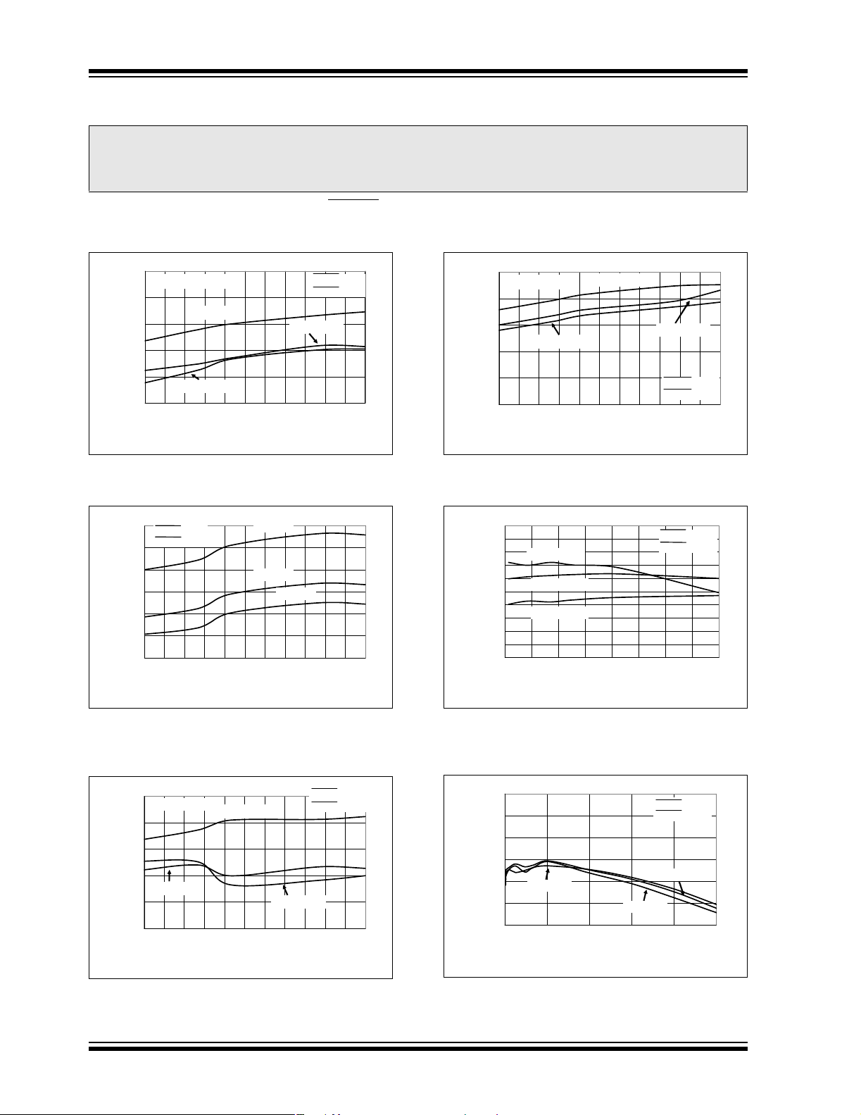
2.0 TYPICAL PERFORMANCE CURVES
Note: The graphs and t ables provided fol lowi ng this note are a st a t istic al summary based on a l im ite d n um ber of
samples and are provided for informational purposes only. The performance characteristics listed herein
are not tested or guaranteed. In some graphs or tables, the data presented may be outside the specified
operating range (e.g., outside specified power supply range) and therefore outside the warranted range.
Note: Unless otherwise indicated, V
(ADJ) = 1.8V, TA= +25°C. Boldface specifications apply over the TA range of -40°C to +85°C. TA= +25°C. Adjustable- or fixed-
V
OUT1
output voltage options can be used to generate the Typical Performance Characteristics.
80
I
= I
= 0 mA SHDN1 = V
OUT1
OUT2
76
72
VIN = 5.5V
68
64
Switcher and LDO (µA)
Q
I
VIN = 3.6V
60
-40 -25 -10 5 20 35 50 65 80 95 110 125
Ambient Temperature (°C)
FIGURE 2-1: IQ Switcher and LDO Current vs. Ambient Temperature (TC1303A,B).
78
SHDN1 = V
IN2
SHDN2 = V
76
74
72
70
68
Switcher and LDO (µA)
Q
I
66
-40 -25 -10 5 20 35 50 65 80 95 110 125
IN2
Ambient Temperature (°C)
IN1
VIN = 5.5V
VIN = 4.2V
VIN = 3.6V
= V
= SHDN1,2 = 3.6V, C
IN2
SHDN2 = V
VIN = 4.2V
OUT1=CIN
IN2
IN2
= 4.7 µF , C
55
I
= 0 mA
OUT2
50
45
40
LDO (µA)
Q
I
35
=1µF, L =4.7µH,
OUT2
VIN = 3.6V
VIN = 5.5V
VIN = 4.2V
SHDN1 = A
SHDN2 = V
30
-40 -25 -10 5 20 35 50 65 80 95 110 125
Ambient Temperature (°C)
FIGURE 2-4: I
LDO Current vs. Ambient
Q
Temperature.
100
95
90
I
= 100 mA
85
80
75
70
Efficiency (%)
65
OUT1
60
V
55
OUT1
I
I
OUT1
OUT1
= 250 mA
= 500 mA
50
2.7 3.05 3.4 3.75 4.1 4.45 4.8 5.15 5.5
Input Voltage (V)
SHDN1 = V
SHDN2 = A
IN2
GND
GND
IN2
FIGURE 2-2: I
Switcher and LDO
Q
Current vs. Ambient Temperature
FIGURE 2-5: V
Input Voltage (V
OUT1
Output Efficiency vs.
OUT1
= 1.2V).
(TC1303C, TC1304).
SHDN1 = V
55
I
= 0 mA
OUT1
VIN = 5.5V
SHDN2 = A
IN2
GND
50
45
40
VIN = 4.2V
Switcher (µA)
Q
I
35
VIN = 3.6V
30
-40 -25 -10 5 20 35 50 65 80 95 110 125
Ambient Temperature (°C)
FIGURE 2-3: I
Switcher Current vs.
Q
Ambient Temperature.
DS21949B-page 10 © 2005 Microchip Technology Inc.
100
95
90
85
Efficiency(%)
80
OUT1
V
75
V
IN1
= 4.2V
70
0.005 0.104 0.203 0.302 0.401 0.5
FIGURE 2-6: V
I
OUT1
(V
OUT1
= 1.2V).
SHDN1 = V
SHDN2 = A
V
IN1
V
= 3.0V
IN1
(A)
I
OUT1
Output Efficiency vs.
OUT1
= 3.6V
IN2
GND
Page 11
TC1303A/TC1303B/TC1303C/TC1304
Note: Unless otherwise indicated, V
V
(ADJ) = 1.8V, TA= +25°C. Boldface specifications apply over the TA range of -40°C to +85°C. TA= +25°C. Adjustable- or fixed-
OUT1
IN1
= V
= SHDN1,2 = 3.6V, C
IN2
OUT1=CIN
= 4.7 µF , C
=1µF, L =4.7µH,
OUT2
output voltage options can be used to generate the Typical Performance Characteristics.
V
100
95
I
= 100 mA
OUT1
90
I
OUT1
= 250 mA
85
80
75
Efficiency(%)
70
OUT1
V
65
60
2.7 3.05 3.4 3.75 4.1 4.45 4.8 5.15 5.5
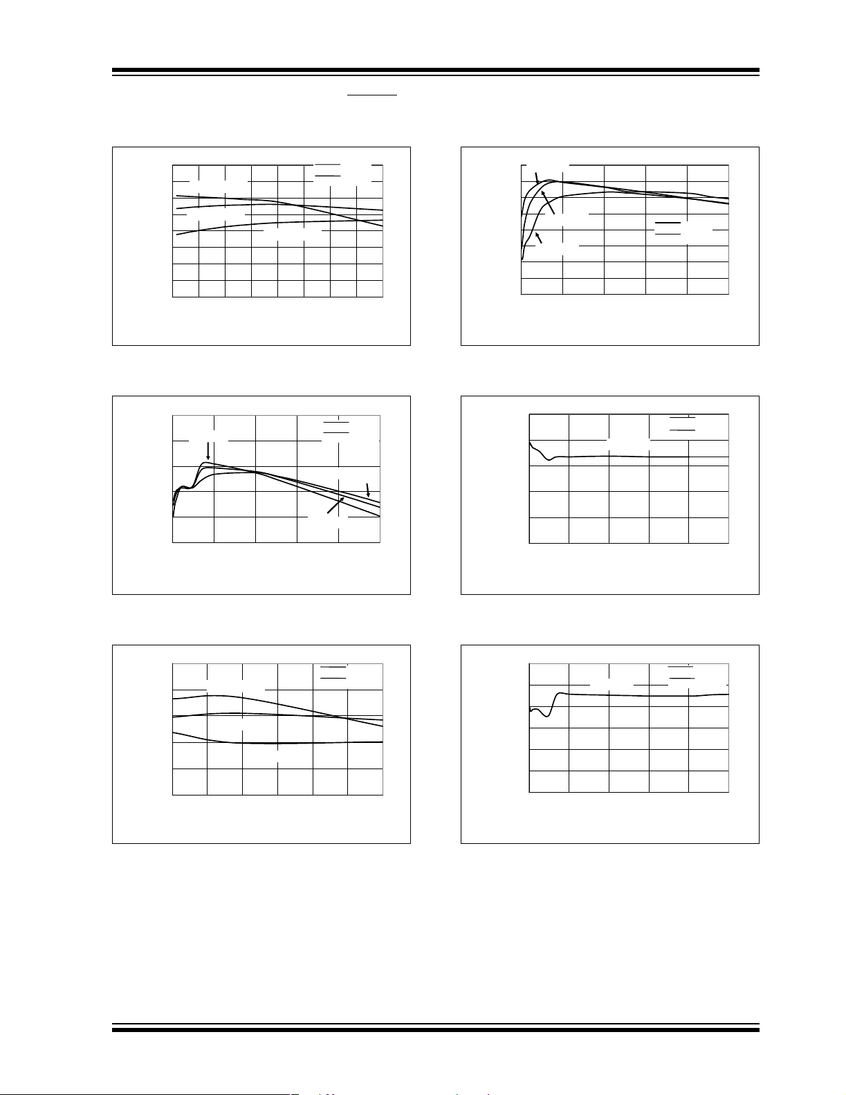
FIGURE 2-7: V
Input Voltage (V
100
95
90
85
Efficiency(%)
OUT1
80
V
75
0.005 0.104 0.203 0.302 0.401 0.5
OUT1
VIN = 3.0V
SHDN1 = V
SHDN2 = A
I
= 500 mA
OUT1
Input Voltage (V)
Output Efficiency vs.
OUT1
= 1.8V).
SHDN1 = V
SHDN2 = A
VIN = 3.6V
I
(A)
OUT1
IN2
GND
VIN = 4.2V
IN2
GND
100
Efficiency (%)
OUT1
V
FIGURE 2-10: V
I
(V
OUT1
1.206
1.202
(V)
OUT1
1.198
V
1.194
= 3.6V
IN1
95
90
85
80
75
V
= 4.2V
IN1
V
= 5.5V
IN1
SHDN1 = V
SHDN2 = A
70
65
60
0.005 0.104 0.203 0.302 0.401 0.5
I
(A)
OUT1
Output Efficiency vs.
OUT1
V
IN1
= 3.6V
SHDN1 = V
SHDN2 = A
OUT1
1.21
= 3.3V).
1.19
0.005 0.104 0.203 0.302 0.401 0.5
I
(A)
OUT1
IN2
GND
IN2
GND
FIGURE 2-8: V
I
OUT1
(V
OUT1
= 1.8V).
100
I
= 100 mA
96
92
88
Efficiency (%)
OUT1
84
V
OUT1
I
OUT1
= 250 mA
80
3.60 3.92 4.23 4.55 4.87 5.18 5.50
FIGURE 2-9: V
Input Voltage (V
OUT1
Output Efficiency vs.
OUT1
SHDN1 = V
SHDN2 = A
I
= 500 mA
OUT1
Input Voltage (V)
Output Efficiency vs.
OUT1
= 3.3V).
IN2
GND
FIGURE 2-11: V
(V
OUT1
(V)
OUT1
V
= 1.2V).
1.82
1.815
1.81
1.805
1.8
1.795
1.79
0.005 0.104 0.203 0.302 0.401 0.5
FIGURE 2-12: V
(V
OUT1
= 1.8V).
OUT1
V
= 3.6V
IN1
OUT1
I
OUT1
vs. I
(A)
vs. I
OUT1
SHDN1 = V
SHDN2 = A
OUT1
IN2
GND
© 2005 Microchip Technology Inc. DS21949B-page 11
Page 12
TC1303A/TC1303B/TC1303C/TC1304
= V
Note: Unless otherwise indicated, V
V
(ADJ) = 1.8V, TA= +25°C. Boldface specifications apply over the TA range of -40°C to +85°C. TA= +25°C. Adjustable- or fixed-
OUT1
IN1
= SHDN1,2 = 3.6V, C
IN2
OUT1=CIN
output voltage options can be used to generate the Typical Performance Characteristics.
= 4.7 µF , C
=1µF, L =4.7µH,
OUT2
3.4
3.36
3.32
(V)
OUT1
3.28
V
3.24
3.2
0.005 0.104 0.203 0.302 0.401 0.5
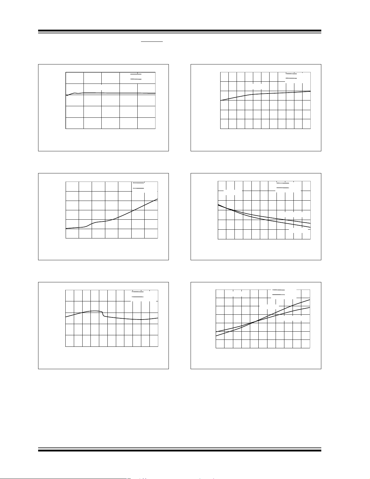
FIGURE 2-13: V
(V
= 3.3V).
OUT1
2.20
2.15
2.10
2.05
2.00
Frequency (MHz)
OUT1
1.95
V
1.90
2.7 3.1 3.5 3.9 4.3 4.7 5.1 5.5
V
= 4.2V
IN1
I
(A)
OUT1
vs. I
OUT1
OUT1
Input Voltage (V)
SHDN1 = V
SHDN2 = A
SHDN1 = V
SHDN2 = A
IN2
GND
IN2
GND
0.820
0.815
0.810
V
IN1
= 3.6V
0.805
FB Voltage (V)
0.800
OUT1
V
0.795
0.790
-40
-25
5
2035506580
-10
Ambient Temperature (°C)
FIGURE 2-16: V
Adjustable Feedback
OUT1
Voltage vs. Ambient Temperature.
0.6
)
"
0.55
TA = 25 °C
0.5
0.45
0.4
Switch Resistance (
0.35
OUT1
V
0.3
3.3 3.5 3.7 3.9 4.1 4.3 4.5 4.7 4.9 5.1 5.3 5.5
Input Voltage (V)
SHDN1 = V
SHDN2 = A
SHDN1 = V
SHDN2 = A
95
IN2
GND
N-Channel
P-Channel
IN2
GND
110
125
FIGURE 2-14: V
OUT1
vs. Input Voltage.
2.00
1.98
1.96
1.94
Frequency (MHz)
1.92
OUT1
V
1.90
-40
-25
-10
5
203550
Ambient Temperature (°C)
FIGURE 2-15: V
OUT1
vs. Ambient Temperature.
Switching Frequency
SHDN1 = V
SHDN2 = A
65
IN2
GND
80
95
110
125
Switching Frequency
FIGURE 2-17: V
OUT1
vs. Input Voltage.
0.65
)
"
0.55
0.45
Switch Resistance (
0.35
OUT1
V
0.6
0.5
0.4
0.3
V
= 3.6V
IN1
-40 -25 -10 5 20 35 50 65 80 95 110 125
Ambient Temperature (°C)
FIGURE 2-18: V
OUT1
vs. Ambient Temperature.
Switch Resist ance
SHDN1 = V
SHDN2 = A
P-Channel
IN2
GND
N-Channel
Switch Resist ance
DS21949B-page 12 © 2005 Microchip Technology Inc.
Page 13

TC1303A/TC1303B/TC1303C/TC1304
= 3.3V
= - 40°C
= + 25°C
= + 85°C
= - 40°C
= + 25°C
= + 85°C
= - 40°C
= + 25°C
= + 85°C
Note: Unless otherwise indicated, V
V
(ADJ) = 1.8V, TA= +25°C. Boldface specifications apply over the TA range of -40°C to +85°C. TA= +25°C. Adjustable- or fixed-
OUT1
IN1
= V
= SHDN1,2 = 3.6V, C
IN2
OUT1=CIN
= 4.7 µF , C
=1µF, L =4.7µH,
OUT2
output voltage options can be used to generate the Typical Performance Characteristics.
I
= 150 mA
0.4
SHDN1 = V
IN2
0.35
SHDN2 = A
GND
0.3
0.25
0.2
Dropout Voltage (V)
0.15
OUT1
V
0.1
-40
-25
-10
5
Ambient Temperature (°C)
FIGURE 2-19: V
Ambient Temperature.
I
OUT1
20
355065
Dropout Voltage vs.
OUT1
80
V
OUT1
= 500 mA
95
110
125
1.492
1.49
1.488
1.486
Output Voltage(V)
1.484
OUT2
V
1.482
FIGURE 2-22: V
Input Voltage (V
1.802
1.800
1.798
1.796
Output Voltage (V)
1.794
OUT2
V
1.792
OUT2
T
A
T
A
T
A
2.73.053.43.754.14.454.85.155.5
Input Voltage (V)
Output Voltage vs.
OUT2
= 1.5V).
OUT2
I
= 150 mA SHDN1 = A
OUT2
T
A
T
A
T
A
SHDN1 = A
SHDN2 = V
SHDN2 = V
2.7 3.05 3.4 3.75 4.1 4.45 4.8 5.15 5.5
Input Voltage (V)
GND
IN2
GND
IN2
FIGURE 2-20: V
OUT1
and V
OUT2
Load Switching Waveforms vs. Time.
FIGURE 2-21: V
OUT1
and V
OUT2
Load Switching Waveforms vs. Time.
Heavy
Light
FIGURE 2-23: V
Input Voltage (V
2.508
2.506
2.504
2.502
2.500
Output Voltage (V)
2.498
OUT2
V
2.496
OUT2
I
= 150 mA
OUT2
3.3 3.5 3.7 3.9 4.1 4.3 4.5 4.7 4.9 5.1 5.3 5.5
FIGURE 2-24: V
Input Voltage (V
OUT2
Output Voltage vs.
OUT2
= 1.8V).
T
A
T
A
T
A
Input Voltage (V)
Output Voltage vs.
OUT2
= 2.5V).
SHDN1 = A
SHDN2 = V
GND
IN2
© 2005 Microchip Technology Inc. DS21949B-page 13
Page 14

TC1303A/TC1303B/TC1303C/TC1304
= - 40°C
= + 25°C
= + 85°C
= 3.3V
= 2.5V
= 1.5V
= 3.3V
= 2.6V
= 1.5V
= V
Note: Unless otherwise indicated, V
V
(ADJ) = 1.8V, TA= +25°C. Boldface specifications apply over the TA range of -40°C to +85°C. TA= +25°C. Adjustable- or fixed-
OUT1
IN1
= SHDN1,2 = 3.6V, C
IN2
OUT1=CIN
output voltage options can be used to generate the Typical Performance Characteristics.
= 4.7 µF , C
=1µF, L =4.7µH,
OUT2
3.298
I
= 150 mA
OUT2
3.297
3.296
3.295
3.294
Output Voltage (V)
3.293
OUT2
V
3.292
3.60 3.92 4.23 4.55 4.87 5.18 5.50
FIGURE 2-25: V
Input Voltage (V
0.30
0.25
0.20
0.15
Dropout Voltage (V)
0.10
OUT2
V
0.05
-40
OUT2
I
OUT2
I
OUT2
-25
-10
Ambient Temperature (°C)
T
A
T
A
T
A
Input Voltage (V)
Output Voltage vs.
OUT2
= 3.3V).
= 300 mA
= 200 mA
5
203550
SHDN1 = A
SHDN2 = V
SHDN1 = A
SHDN2 = V
658095
GND
IN2
0.005
0.000
-0.005
-0.010
-0.015
SHDN1 = A
V
OUT2
SHDN2 = V
V
OUT2
GND
IN2
I
= 100 µA
OUT2
-0.020
-0.025
Line Regulation (%/V)
-0.030
OUT2
V
-0.035
-40 -25 -10 5 20 35 50 65 80 95 110 125
V
OUT2
Ambient Temperature (°C)
FIGURE 2-28: V
Line Regulation vs.
OUT2
Ambient Temperature.
0.1
V
= 3.6V SHDN1 = A
0.0
IN2
V
OUT2
SHDN2 = V
GND
IN2
-0.1
-0.2
Load Regulation (%)
-0.3
OUT2
V
-0.4
-40
-25
110
125
-10
V
OUT2
5
20
35
50
65
Ambient Temperature (° C)
GND
IN2
V
OUT2
80
95
110
125
FIGURE 2-26: V
OUT2
Ambient Temperature (V
0.3
0.2
0.1
Dropout Voltage (V)
OUT2
V
0.0
I
OUT2
I
OUT2
= 300 mA
= 200 mA
-40 -25 -10 5 20 35 50 65 80 95 110 125
Ambient Temperature (°C)
FIGURE 2-27: V
OUT2
Ambient Temperature (V
Dropout Voltage vs.
= 2.5V).
OUT2
SHDN1 = A
SHDN2 = V
Dropout Voltage vs.
= 3.3V).
OUT2
GND
IN2
FIGURE 2-29: V
Load Regulation vs.
OUT2
Ambient Temperature.
350
325
300
275
250
225
PG Active Delay Time (ms)
200
-40 -25 -10 5 20 35 50 65 80 95 110 125
VIN = 3.6V
SHDN1 = V
SHDN2 = V
Ambient temperature (°C)
IN2
IN2
FIGURE 2-30: PG Active Delay Time-out vs. Ambient Temperature.
DS21949B-page 14 © 2005 Microchip Technology Inc.
Page 15

TC1303A/TC1303B/TC1303C/TC1304
Note: Unless otherwise indicated, V
V
(ADJ) = 1.8V, TA= +25°C. Boldface specifications apply over the TA range of -40°C to +85°C. TA= +25°C. Adjustable- or fixed-
OUT1
IN1
= V
= SHDN1,2 = 3.6V, C
IN2
OUT1=CIN
= 4.7 µF , C
=1µF, L =4.7µH,
OUT2
output voltage options can be used to generate the Typical Performance Characteristics.
96
)
VIN = 3.6V
OUT2
95
94
PG Threshold Hi
SHDN1 = V
SHDN2 = V
IN2
IN2
93
92
PG Threshold Low
91
PG Threshold (% of V
90
-40 -25 -10 5 20 35 50 65 80 95 110 125
Ambient Temperature (°C)
FIGURE 2-31: PG Threshold Voltage vs. Ambient Temperature.
(V)
OL
PG V
0.02
0.018
0.016
0.014
0.012
0.01
VIN = 3.6V
IOL = 1.2 mA
-25
-10
5
-40
Ambient Temperature (°C)
203550
SHDN1 = V
SHDN2 = V
658095
IN2
IN2
110
FIGURE 2-34: V
Rejection vs. Frequency.
125
0
SHDN1 = GND
-10
-20
-30
-40
PSRR (dB)
-50
OUT2
-60
V
V
I
C
OUT2
OUT2
= 0 µF
IN
= 1.5V
= 30 mA
C
OUT2
C
= 1.0 µF
= 4.7 µF
OUT2
-70
-80
0.01 0.1 1 10 100 1000
Frequency (kHz)
Power Supply Ripple
OUT2
10
SHDN1 = A
SHDN2 = V
Hz)
1
Noise (μV/
0.1
VIN = 3.6V
OUT2
V
I
OUT2
OUT2
= 2.5V
= 50 mA
V
0.01
0.01 0.1 1 10 100 1000 10000
Frequency (kHz)
GND
IN2
FIGURE 2-32: PG Output Voltage Level
FIGURE 2-35: V
Noise vs. Frequency.
OUT2
Low vs. Ambient Temperature.
V
= 2.8V
3.0
2.5
2.0
(V)
OH
1.5
PG V
1.0
VIN = 3.6V
0.5
= 500 µA
I
OH
0.0
-40 -25 -10 5 20 35 50 65 80 95 110 125
FIGURE 2-33: PG Output Voltage Level High vs. Ambient Temperature.
OUT2
V
= 2.5V
OUT2
V
= 1.5V
OUT2
Ambient Temperature (°C)
SHDN1 = V
SHDN2 = V
IN2
IN2
FIGURE 2-36: V
Load Step Response
OUT1
vs. Time.
© 2005 Microchip Technology Inc. DS21949B-page 15
Page 16

TC1303A/TC1303B/TC1303C/TC1304
= V
Note: Unless otherwise indicated, V
V
(ADJ) = 1.8V, TA= +25°C. Boldface specifications apply over the TA range of -40°C to +85°C. TA= +25°C. Adjustable- or fixed-
OUT1
output voltage options can be used to generate the Typical Performance Characteristics.
IN1
= SHDN1,2 = 3.6V, C
IN2
OUT1=CIN
= 4.7 µF , C
=1µF, L =4.7µH,
OUT2
FIGURE 2-37: V
vs. Time.
FIGURE 2-38: V
Response vs. Time.
Load Step Response
OUT2
and V
OUT1
OUT2
Line Step
FIGURE 2-40: V
OUT1
and V
OUT2
Shutdown
Waveforms.
FIGURE 2-41: Power-Good Output Timing.
FIGURE 2-39: V
OUT1
and V
OUT2
Start-up
Waveforms.
DS21949B-page 16 © 2005 Microchip Technology Inc.
FIGURE 2-42: Start-up Waveforms (TC1304).
Page 17

TC1303A/TC1303B/TC1303C/TC1304
Note: Unless otherwise indicated, V
V
(ADJ) = 1.8V, TA= +25°C. Boldface specifications apply over the TA range of -40°C to +85°C. TA= +25°C. Adjustable- or fixed-
OUT1
output voltage options can be used to generate the Typical Performance Characteristics.
IN1
= V
= SHDN1,2 = 3.6V, C
IN2
OUT1=CIN
= 4.7 µF , C
=1µF, L =4.7µH,
OUT2
FIGURE 2-43: Shutdown Waveforms (TC1304).
© 2005 Microchip Technology Inc. DS21949B-page 17
Page 18

TC1303A/TC1303B/TC1303C/TC1304
3.0 PIN DESCRIPTIONS
The descriptions of the pins are listed in Table 3-1.
TABLE 3-1: PIN FUNCTION TABLE
Pin No.
TC1303
Name
1 SHDN2
1 — SHDN
TC1304
Name
Function
— Active Low Shutdown Input for LDO Output Pin
Active Low Shutdown Input both Buck Regulator Output and LDO Output.
Initiates sequencing up and down
2V
3V
IN2
OUT2
V
V
IN2
OUT2
Analog Input Supply Voltage Pin
LDO Output Voltage Pin
4 PG PG Power-Good Output Pin
5A
6V
GND
FB/VOUT1VFB/VOUT1
A
GND
Analog Ground Pin
Buck Feedback Voltage (Adjustable Version) / Buck Output Voltage
(Fixed Version) Pin
7 SHDN1 — Active Low Shutdown Input for Buck Regulator Output Pin
7—A
8V
9L
10 P
IN1
X
GND
EP Exposed
Pad
GND
V
IN1
L
P
GND
Exposed
Pad
3.1 TC1303 LDO Shutdown Input Pin
(SHDN2
SHDN2 is a logic-level input us ed to turn the LDO Regulator on and off. A logic-high (> 45% of V
enable the regulator output. A logic-low (< 15% of V
will ensure that the output is turned off.
)
3.2 TC1304 Shutdown Input Pin
(SHDN
SHDN is a logic-level inp ut used to initia te the sequencing of the LDO output, then the buck regulator output.
A logic-high (> 45% of V
outputs. A logic-low (< 15% of V
outputs are turned off.
)
), will enable the regulator
IN
IN
3.3 LDO Input Voltage Pin (V
V
is a LDO power input su pply pin. C onnect vari able
IN2
input voltage source to V
. Connect V
IN2
together with board traces as short as possible. V
provides the input voltage for the LDO. An additional
capacitor can be added to lower the LDO regulator
input ripple voltage.
3.4 LDO Output Voltage Pin (V
V
is a regulated LDO output voltage pin. Connect
OUT2
a 1 µF or larger capacitor to V
OUT2
and A
Analog Ground Pin
Buck Regulator Input Voltage Pin
Buck Inductor Output Pin
X
Power Ground Pin
For the DFN p ackage, the c enter expos ed p ad i s a t hermal p ath to remove
heat from the device. Elect rically thi s pad is at ground po tential and sh ould
be connected to A
GND
3.5 Power-Good Output Pin (PG)
PG is an output level indicating that V
within 94% of regulation. The PG output is configured
), will
IN
)
IN
as a push-pull for the TC1303B and open-drain output
for the TC1303A, TC1303C and TC1304.
3.6 Analog Ground Pin (A
A
is the analog ground connection. Tie A
GND
analog portion of the ground plane (A
physical layout information in Section 5.0 “Application
Circuits/Issues” for grounding recommendations.
3.7 Buck Regulator Output Sense Pin
) will ensure that the
)
IN2
and V
IN1
IN2
IN2
For V
the center of the output voltage divider to the V
For fixed-output voltage options, connect the output of
the buck regulator to this pin (V
3.8 Buck Regulator Shutdown Input
(V
FB/VOUT1
adjustable-output voltage options, connect
OUT1
Pin (SHDN1
SHDN1 is a logic-level input used to turn the buck
OUT2
for proper
GND
)
regulator on and off. A logic-high (> 45% of V
enable the regulator output. A logic-low (< 15% of V
will ensure that the output is turned off.
operation.
(LDO) is
OUT2
)
GND
to the
GND
). See the
GND
)
pin.
FB
).
OUT1
)
), will
IN
)
IN
DS21949B-page 18 © 2005 Microchip Technology Inc.
Page 19

TC1303A/TC1303B/TC1303C/TC1304
3.9 Buck Regulator Input Voltage Pin
(V
)
IN1
V
is the buck regulator power input supply pin.
IN1
Connect a variable input voltage source to V
Connect V
short as possible.
IN1
and V
together with board traces as
IN2
IN1
3.10 Buck Inductor Output Pin (LX)
Connect LX directly to the buck inductor. This pin
carries large signal-level current; all connections
should be made as short as possible.
3.1 1 Power Ground Pin (P
Connect all large-signal level ground returns to P
These large-signal, level ground traces should have a
.
small loop area and length to prevent coupling of
switching noise to sensitive traces. Please see the
physical layout information supplied in Section 5.0
“Application Circuits/Issues” for grounding
recommendation s.
GND
)
.
GND
3.12 Exposed Pad (EP)
For the DFN package, connect the EP to A
vias into the A
GND
plane.
GND
, with
© 2005 Microchip Technology Inc. DS21949B-page 19
Page 20

TC1303A/TC1303B/TC1303C/TC1304
4.0 DETAILED DESCRIPTION
4.1 Device Overview
The TC1303/TC1304 combines a 500 mA synchronous buck regulator with a 300mA LDO and a powergood output. This uniq ue combination provi des a small,
low-cost solution for applications that require two or
more voltage ra ils. The buck re gulator c an deliv er highoutput current over a wide range of input-to-output
voltage ratios while maintaining high efficiency. This is
typically used for the lower-voltage, high-current
processor core. The LDO is a minimal parts-count
solution (single-output capacitor), providing a regulated
voltage for an auxiliary rail. The typical LDO dropout
voltage (137 mV @ 200 mA) allows the use of very low
input-to-output LDO differential voltages, minimizing
the power loss internal to the LDO pass transistor. A
power-good output i s prov ided, indicati ng tha t th e buck
regulator output, the LDO output or both outputs are in
regulation. Additional features include independent
shutdown inputs (TC1303), UVLO, output voltage
sequencing (TC1304), overcurrent and
overtemperature shutdown.
4.2 Synchronous Buck Regulator
The synchro nous buc k regulat or is capab le of su pplying a 500 mA continuous output current over a wide
range of input and output voltages. The output voltage
range is from 0.8V (min) to 4.5V (max). The regulator
operates in three d ifferen t modes, a utomatic ally se lecting the most efficient mode of operation. During heavy
load conditions, the TC1303/TC1304 buck converter
operates at a high, fixed frequency (2.0 MHz) using
current mode control. This mi nim iz es outp ut ripp le and
noise (less than 8 mV peak-to-peak ripple) while mai ntaining high efficiency (typically > 90%). For st a ndby or
light load applications, the buck regulator will automatically switch to a power-saving Pulse Frequency
Modulation (PFM) mod e. T his m in im ize s the quiescent
current draw on the battery, while keeping the buck
output voltage in regulation. The typical buck PFM
mode current is 38 µA. The buck regulator is capable of
operating at 100% duty cycle, minimizing the voltage
drop from input-to-output for wide input, batterypowered applications. For fixed -outpu t volta ge applic ations, the feedba ck d ivide r and c ontrol loop compe nsation components are integrated, eliminating the need
for external components. The buck regulator output is
protected ag ainst overcurrent, sh ort circuit and overtemperature. While shut down, the synchronous buck
N-channel and P-channel switches are off, so the L
pin is in a high-impedance state (this allows for
connecting a source on th e output of the b uck regulator
as long as its voltage does not exceed the input
voltage).
4.2.1 FIXED-FREQUENCY PWM MODE
While operating in Pulse Width Modulation (PWM)
mode, the TC1303/TC1304 buck regulator switches at
a fixed, 2.0 MHz frequency. The PWM mode is suited
for higher load current operation, maintaining low output noise and high conv ersion ef ficie ncy. PFM-to-PWM
mode transition is initiated for any of the following
conditions:
• Continuous inductor current is sensed
• Inductor peak current excee ds 100mA
• The buck regulator output voltage has dropped
out of regulation (step load has occurred)
The typical PFM-to-PWM threshold is 80 mA.
4.2.2 PFM MODE
PFM mode is entered w hen the out put load on th e buck
regulator is very light. Once detected, the converter
enters the PFM mode automatically and begins to skip
pulses to minimize unnecessary quiescent current
draw by reducing the number of switching cycles per
second. The typical quiescent current for the switching
regulator is less than 35 µA. The transition from PWM
to PFM mode occurs when discontinuous inductor
current is sensed or the peak inductor current is less
than 60 mA (typ.). The typical PWM to PFM mode
threshold is 30 mA. For low input-to-output differential
voltages, the PWM-to-PF M mode th reshol d can be low
due to the lack of ripple current. I t is reco mmended that
be one volt greater than V
V
IN1
transitions.
for PWM-to-PFM
OUT1
4.3 Low Drop Out Regulator (LDO)
The LDO output is a 300 mA low-dropout linear regulator that provides a regulated output voltage with a
single 1 µF external capacitor. The output voltage is
available in fixed options only, ranging from 1.5V to
3.3V. The LDO is stable using ceramic output capaci-
tors that inherently provide lower output noise and
reduce the size and cost of the regulator solution. The
quiescent current consumed by the LDO output is
typically less than 40 µA, with a typical dropout voltage
of 137 mV at 200 mA. While operating in Dropout
mode, the LDO quiescent current will increase, minimizing the necessa ry voltage dif ferential nee ded for the
LDO output to maintain regulation. The LDO output is
protected against overcurrent and overtemperature
conditions.
X
DS21949B-page 20 © 2005 Microchip Technology Inc.
Page 21

TC1303A/TC1303B/TC1303C/TC1304
4.4 Power-Good
A Power-Good (PG) output signal is generated based
off of the buck regulator output voltage (V
LDO output voltage (V
) or the combination of both
OUT2
outputs. A fixed delay time of approximately 262 ms is
generated once the monitored output voltage is above
the power-good thresh old (ty pic al ly 94% of V
the monitored output voltage falls out of reg ul atio n, th e
falling PG threshold is typically 92% of the output
voltage. The PG outpu t sign al is pull ed up to th e outp ut
voltage, indicating that power is good and pulled low,
indicating that the output is out of regulation. The typical quiescent current draw for power-good circuitry is
less than 10 µA.
If the monitored output voltage falls below the powergood threshold, the power-good ou tput will transition to
the Low state. The power-g ood circui try has a 16 5 µs
delay when detecting a falling output voltage. This
helps to in crease the noise imm unity of th e power-good
output, avoiding fals e triggerin g of the PG signal d uring
line and load transients.
V
TH_H
V
OUT1
or V
OUT2
t
RPU
V
OH
t
RPD
OUT1
OUTX
), the
). As
4.5 Power Good Output Options
There are three monitoring options for the TC1303
family.
For the TC1303A, only the buck regulator output
voltage (V
depends only on V
For the TC1303B, only the LDO ou tput volt age (V
is monitored. The PG output signal depends only on
.
V
OUT2
For the TC1303C and TC1304, both the buck regu lator
output voltage and LDO output voltage are monitored.
If either one of the output s fa ll out of regulati on, the PG
will be low . On ly if b oth V
PG voltage threshold limits will the PG output be high.
For the TC1303A,C and TC1304, the PG output pin is
open drain and can be pu ll ed up to any level within th e
given absolute maximum ratings (A
+ 0.3V).
TABLE 4-1: PG AVAILABLE OPTIONS
Part
Number
TC1303A Yes No Open-Drain
TC1303B No Yes Push-Pull
TC1303C Yes Yes Open-Drain
TC1304 Yes Yes Open-Drain
) is monitored. The PG output signal
OUT1
PG Output
(V
OUT1
Buck
OUT1
.
)
OUT1
and V
PG
Output
LDO
(V
OUT2
are within the
OUT2
- 0.3V) to (V
GND
PG Output
)
Type
(V
OUT2
OUT2
)
)
IN
PG
FIGURE 4-1: Power-Good Timing.
V
OL
© 2005 Microchip Technology Inc. DS21949B-page 21
Page 22

TC1303A/TC1303B/TC1303C/TC1304
4.6 TC1304 Sequencing
The TC1304 devic e fe atu r es an integrated sequen cin g
option. A sequencing circ uit using only the SHDN
(Pin1), will turn on the LDO output (V
SHDN
* 160 µ s delay on trailing edge
OUT2
FIGURE 4-2: TC1304 Sequencing Circuit.
TC1304
Power Up Timing From SHDN
V
IN1/VIN2
input,
) and delay
V
OUT2
Enable
V
OUT1
Enable
the turn on of the Buck Regulator output (V
the LDO output is in regulation. During power-down,
the sequencing circuit will turn off the Buck Regulator
output prior to turning off LDO output.
160 µs Delay*
To PG
Delay CKT.
160 µs Delay*
92% of V
92% of V
+
–
OUT2
+
–
OUT1
4.7 Soft Start
Both outputs of the TC1303/TC1304 are controlled
during start-up. Less than 1% of V
shoot is observed du ring s tart-up f rom V
the UVLO voltage or either S
HDN1 or SHDN2 being
enabled.
OUT1
or V
rising above
IN
OUT1
OUT2
) until
over-
SHDN
500 µs
V
OUT1
+ t
t
WK
S
V
OUT2
300ms
Power Good
FIGURE 4-3: TC1304 Power-up Timing
from SHDN
.
4.8 Overtemperature Protection
The TC1303/TC1304 has an integrated overtemperature protection circuit that monitors the device junction
temperature and shuts the device off if the junction temperature exceeds the typical 165°C threshold. If the
overtemperature threshold is reached, the soft start is
reset so that, once the junction temperature cools to
approximately 155°C, the device will automatically
restart.
DS21949B-page 22 © 2005 Microchip Technology Inc.
Page 23

TC1303A/TC1303B/TC1303C/TC1304
5.0 APPLICATION CIRCUITS/ISSUES
5.1 Typical Applications
The TC1303/TC1304 50 0 mA buck regulator + 300 mA
LDO with power-good operates over a wide input voltage range (2. 7 V t o 5. 5 V) a nd i s i d ea l f or s i ng le - c el l LiIon battery-powered applications, USB-powered applications, three-cell NiMH or NiC d applications an d 3V to
5V regulated input appl icatio ns. The 10-pin MSOP and
3X3 DFN packages provide a small footprint with
minimal external components.
5.2 Fixed Output Application
A typical V
shown in “Typical Application Circuits”. A 4.7 µF
ceramic input capacitor, 4.7 µF V
V
IN1
capacitor, 1.0 µF ceramic V
inductor make up the entire external component solution for this dual-output application. No external dividers or compensation components are necessary. For
this application, the in put volta ge range is 2.7V to 4.2V,
= 1.5V at 500 mA, while V
V
OUT1
300 mA.
5.3 Adjustable Output Application
A typical V
shown in “Typical Application Circuits”. For this
application, the buck reg ulator ou tput vol tage is adjus table by using two external resistors as a voltage
divider. For adjustable-output voltages, it is recommended that the top resistor divider value be 200 k
The bottom resistor divider can be calculated using the
following formula:
EQUATION 5-1:
fixed-output voltage application is
OUT1
capacitor and 4.7 µH
OUT2
adjustable output application is also
OUT1
V
⎛⎞
R
BOTRTOP
--------------------------------
×=
⎝⎠
V
OUT1VFB
OUT1
OUT2
FB
–
ceramic
=2.5V at
Ω.
An additional V
capacitor can be added to reduce
IN2
high-frequency noise on the LDO input voltage pin
(V
). This additional cap aci tor (1 µF on page 5) is not
IN2
necessary for typical applications.
5.4 Input and Output Capacitor Selection
As with all buck-derived dc-dc s witching re gulators , the
input current is pulled from the source in pulses. This
places a burden on the TC1303/TC1304 input filter
capacitor. In most applications, a minimum of 4.7 µF is
recommended on V
pin). In applications that have high source impedance,
or have long leads, (10 inches) connecting to the input
source, additional capacitance should be used. The
capacitor type can b e ele ctrolytic (aluminum, t a ntalum,
POSCAP, OSCON) or ceramic. For most portable electronic applications, ceramic capacitors are preferred
due to their small size and low cost.
For applications tha t requir e very low noise on the LDO
output, an additional capacitor (typically 1 µF) can be
added to the V
IN2
Low ESR electrolytic or ceramic can be used for the
buck regulator output capacitor. Again, ceramic is
recommended because of its physical attributes and
cost. For most applications , a 4.7 µF is recommended.
Refer to Table 5-1 for recommended values. Larger
capacitors (up to 22 µF) can be used. There are some
advantages in load step performance when using
larger value capacitors. Ceramic materials X7R and
X5R have low temperature coefficients and are well
within th e acceptable ESR range required.
T ABLE 5-1: TC1303A, TC1303B, TC1303C,
C(V
min 4.7 µF none 4.7 µF 1 µF
max none none 22 µF 10 µF
(buck regulator input voltage
IN1
pin (LDO input voltage pin).
TC1304 RECOMMENDED
CAPACITOR VALUES
)C(V
IN1
)C
IN2
OUT1
C
OUT2
Example:
R
V
R
R
=200kΩ
TOP
=2.1V
OUT1
=0.8V
V
FB
=200kΩ x (0.8V/(2.1V – 0.8V))
BOT
=123kΩ (Standard Value = 121 kΩ)
BOT
For adjustable-output applications, an additional R-C
compensation is necessary for the buck regulator
control loop stability. Recommended values are:
R
COMP
C
COMP
© 2005 Microchip Technology Inc. DS21949B-page 23
=4.99kΩ
=33pF
Page 24
TC1303A/TC1303B/TC1303C/TC1304
5.5 Inductor Selection
For most applications, a 4.7 µH inductor is recommended to minimize noise. There are many different
magnetic core materi als an d p a ck age options to select
from. That decision is based on size, cost and acceptable radiated energy levels. Toroid and shielded ferrite
pot cores will have low radiated energy, but tend to be
larger and highe r is cost. W ith a typi cal 2.0 MHz switching frequency, the inductor ripple current can be
calculated based on the following formulas.
EQUATION 5-2:
V
OUT
DutyCycle
Duty cycle represents the percentage of switch-on
time.
EQUATION 5-3:
T
DutyCycle
ON
Where:
= Switching Frequency.
F
SW
=
-------------
V
IN
×=
1
----------
F
SW
T ABLE 5-2: TC1303A, TC1303B, TC1303C,
TC1304 RECOMMENDED
INDUCTOR VALUES
Part
Number
Coiltronics
Value
(µH)
®
DCR
Ω
(MAX)
MAX
I
DC
(A)
SD10 2.2 0.091 1.35 5.2, 5.2, 1.0 max.
SD10 3.3 0.108 1.24 5.2, 5.2, 1.0 max.
SD10 4.7 0.154 1.04 5.2, 5.2, 1.0 max.
Coiltronics
SD12 2.2 0.075 1.80 5.2, 5.2, 1.2 max.
SD12 3.3 0.104 1.42 5.2, 5.2, 1.2 max.
SD12 4.7 0.118 1.29 5.2, 5.2, 1.2 max.
Sumida Corporation
®
CMD411 2.2 0.116 0.950 4.4, 5.8, 1.2 max.
CMD411 3.3 0.174 0.770 4.4, 5.8, 1.2 max.
CMD411 4.7 0.216 0.750 4.4, 5.8, 1.2 max.
Coilcraft
®
1008PS 4.7 0.35 1.0 3.8, 3.8, 2.74 max.
1812PS 4.7 0.11 1.15 5.9, 5.0, 3.81 max
Size
WxLxH (mm)
The inductor ac ripple current can be calculated using
the following relationship:
EQUATION 5-4:
ΔI
L
VLL
--------
×=
Δt
Where:
= voltage ac ross the indu ctor (VIN – V
V
L
OUT
)
Δt = on-time of P-channel MOSFET
Solving for ΔIL= yields:
EQUATION 5-5:
V
L
------
ΔI
L
When considering inductor ratings, the maximum DC
current rating of t he inductor should b e at leas t equal to
the maximum bu ck reg u lat or lo ad cu rr ent ( I
one half of the peak-to-peak inductor ripple current
(1/2 * ΔI
buck converter I
). The inductor DC resistance can add to the
L
2
R losses. A rating of less than 200 mΩ
is recommended . Overall e ffi ciency will be im proved b y
using lower DC resistance inductors.
Δt×=
L
), plus
OUT1
5.6 Thermal Calculations
5.6.1 BUCK REGULATOR OUTPUT
(V
The TC1303/TC1304 is availab le in two di fferen t 10-pin
packages (MSOP and 3X3 DFN). By calculating the
power dissipation and applying the package thermal
resistance, (θ
The maximum continuous junction temperature rating
for the TC1303/TC1304 is +125°C.
To quickly estimate the internal power dissipation for
the switching buck regulator, an empirical calculation
using measured efficiency can be used. Given the
measured efficiency (Section 2.0 “Typical Perfor-
mance Curves”), the internal power dissipation is
estimated below:
EQUATION 5-6:
V
×
OUT1IOUT1
⎛⎞
-------------------------------------
⎝⎠
Efficiency
The first term is equal to the input power (definition of
efficiency, P
equal to the delivered power. The difference is internal
power dissipation. This is an estimate assuming that
most of the power lost is internal to the TC1303B.
There is some percentage of power lost in the buck
inductor, with very little loss in the input and output
capacitors.
)
OUT1
), the junction tempe rature is estim ated.
JA
V
OUT/PIN =
×()– P
OUT1IOUT1
Efficiency). The second term is
=
Dissipation
DS21949B-page 24 © 2005 Microchip Technology Inc.
Page 25

TC1303A/TC1303B/TC1303C/TC1304
As an example, for a 3.6V input, 1.8V ou tput with a load
of 400 mA, the efficiency taken from Figure 2-8 is
approximat ely 84%. The intern al power dissipatio n is
approximately 137 mW.
5.6.2 LDO OUTPUT (V
OUT2
)
The internal power dissipation within the
TC1303/TC1304 LDO is a function of input voltage,
output voltage an d output cu rrent. Equa tion5-7 can be
used to calculate the internal power dissipation for the
LDO.
EQUATION 5-7:
P
LDO
Where:
The maximum power dissipation capability for a
package can be calculated given the junction-toambient thermal resistance and the maximum ambient
temperature for the applica tion. The foll owing equ ation
can be used to determine the package’s maximum
internal power dissipation.
P
LDO
V
IN(MAX)
V
OUT(MIN)
V
IN MAX )()VOUT2 MIN()
–()I
×=
= LDO Pass device internal
power dissipation
= Maximum input voltage
= LDO mi nimum output voltage
OUT2 M AX )()
5.6.3 LDO POWER DISSIPATION
EXAMPLE
Input Voltage
VIN =5V±10%
LDO Output Voltage and Current
= 3.3V
V
OUT
I
=300mA
OUT
Internal Power Dissipation
P
LDO(MAX)
P
P
=(V
= (5.5V – 0.975 x 3.3V ) x 300 mA
LDO
= 684.8 mW
LDO
IN(MAX)
– V
OUT2(MIN)
) x I
OUT2(MAX)
5.7 PCB Layout Information
Some basic design guidelines should be used when
physically placing the TC1303/TC1304 on a Printed
Circuit Board (PCB). The TC1303/TC1304 has two
ground pins , identified as A
P
(power ground). By separating grounds, it is
GND
possible to minimize the switching frequency noise on
the LDO output. Th e firs t priori ty, while placing external
components on the board, is the input capacitor (C
Wiring should be short and wide; the input current for
the TC1303/TC1304 can be as high as 800 mA. The
next priority would be the buck regulator output
capacitor (C
) and inductor (L1). All three of these
OUT1
(analog ground) and
GND
IN1
components are placed near their respective pins to
minimize trace length. The C
IN1
and C
returns are connected closely together at the P
plane. The LDO optional input capacitor (C
LDO output c apaci tor C
are returned to the A
OUT2
OUT1
capacitor
GND
) and
IN2
GND
plane. The analog ground plane and power ground
+V
OUT1
P
GND
+V
IN1
Plane
). All
1
GND
plane are connected at one point (shown near L
other signals (SHDN1
, SHDN2, feedback in the
adjustable-output case) should be referenced to A
and have the A
- Via
* C
Optional
IN2
A
GND
C
IN2
+V
IN2
+V
OUT2
C
O
A
GND
plane underneath them.
GND
A
to P
GND
1
2
3
4
T
U
2
5
GND
L
1
TC1303B
A
GND
10
9
8
7
6
Plane
C
C
OUT1
N
I
P
1
GND
FIGURE 5-1: Component Placement, Fixed 10-Pin MSOP.
There will be some difference in la yout for the 10-p in
DFN package due to the thermal pad. A typical fixedoutput DFN layout is shown below. For the DFN layout,
IN1
to V
the V
the board around the TC1303/TC1304 thermal pad.
- Via
* C
A
GND
+V
IN2
+V
OUT2
A
GND
).
FIGURE 5-2: Component Placement, Fixed 10-Pin DFN.
connection is routed on the bottom of
IN2
A
to P
GND
GND
Optional
IN2
C
OUT1
PGND
C
IN2
C
O
U
1
2
3
4
T
2
5
A
GND
10
9
8
7
6
TC1303B
Plane
C
N
1
I
P
L
1
GND
+V
P
GND
+V
Plane
OUT1
IN1
© 2005 Microchip Technology Inc. DS21949B-page 25
Page 26

TC1303A/TC1303B/TC1303C/TC1304
5.8 Design Example
V
V
=2.0V @ 500mA
OUT1
=3.3V @ 300mA
OUT2
VIN=5V±10%
L = 4.7µH
Calculate PWM mode inductor ripple current
Nominal Duty
Cycle = 2.0V/5.0V = 40%
P-channel
Switch-on time = 0.40 x 1/(2 MHz) = 200 ns
V
L
=(VIN-V
OUT1
)=3V
ΔIL=(VL/L) x TON=128mA
Peak inductor current:
I
L(PK)
=I
+1/2ΔIL= 564 mA
OUT1
Switcher power loss:
Use efficiency estimate for 1.8V from Figure 2-8
Efficiency = 84%, P
DISS1
= 190 mW
Resistor Divider:
R
= 200 kΩ
TOP
R
= 133 kΩ
BOT
LDO Output:
P
P
P
=(V
DISS2
DISS2
DISS2
V
OUT2(MIN)
= (5.5V – (0.975) x 3.3V) x 30 0 mA
= 684.8 mW
IN(MAX)
–
)xI
OUT2(MAX)
Total
Dissipation = 190 mW + 685 mW = 874 mW
Junction Temp Rise and Maximum Ambient
Operating Temperature Calculations
10-Pin MSOP (4-Layer Board with internal Planes)
=113°C/Watt
Rθ
JA
Junction Temp.
Rise = 874 mW x 113° C/Watt = 98.8°C
Max. Ambient
Temperature = 125°C - 98.8°C
Max. Ambient
Temperature = 26.3°C
10-Pin DFN
= 41° C/Watt (4-Layer Board with
Rθ
JA
internal planes and 2 vias)
Junction Temp.
Rise = 874 mW x 41° C/Watt = 35.8°C
Max. Ambient
Temperature = 125°C - 35.8°C
Max. Ambient
Temperature = 89.2°C
This is above the +85°C max. ambient temperature.
DS21949B-page 26 © 2005 Microchip Technology Inc.
Page 27

TC1303A/TC1303B/TC1303C/TC1304
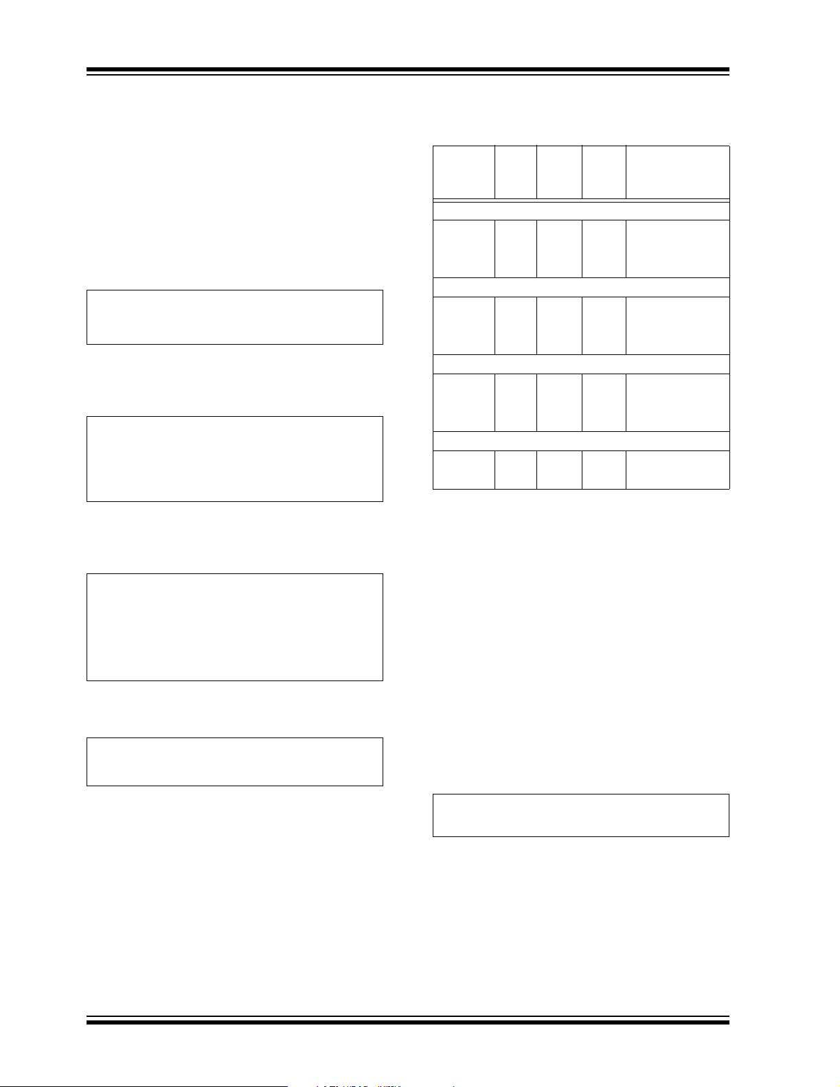
6.0 PACKAGING INFORMATION
6.1 Package Marking Information
10-Lead MSOP* Example:
Example:
10-Lead DFN
— 1 = TC1303B
XXXXXX
YWWNNN
11H0/E
520256
— 2 = TC1303A
— 3 = TC1303C
— 4 = TC1304
— 1 = 1.375V V
— H = 2.6V V
OUT2
OUT1
XXXX
YYWW
NNN
11H0
0520
— 0 = Default
* The MSOP package for this device has not
Third letter represents V
configuration:
OUT2
been qualified at the time of this publication.
Contact your Microchip sales office for
availability.
Code V
OUT2
A 3.3V J 2.4V S 1.5V
Code V
OUT1
Code V
B3.2VK2.3VT —
Second letter represents V
Code V
OUT1
Code V
A3.3VJ2.4VS1.5V
B3.2VK2.3VT1.4V
C3.1VL2.2VU1.3V
D 3.0V M 2.1V V 1.2V
E 2.9V N 2.0V W 1.1V
F 2.8V O 1.9V X 1.0V
G2.7VP1.8VY0.9V
H 2.6V Q 1.7V Z Adj
I 2.5V R 1.6V 1 1.375V
configuration:
OUT1
OUT1
Code V
OUT1
C3.1VL2.2VU —
D3.0VM2.1VV —
E2.9VN2.0VW —
F2.8VO1.9VX —
G2.7VP1.8VY —
H2.6VQ1.7VZ —
I2.5VR1.6V
Fourth letter represents +50 mV Increments:
Code Code
0 Default 2 +50 mV to V2
1 +50 mV to V1 3 +50 mV to V1
and V2
256
OUT2
Legend: XX...X Customer-specific information
Y Year code (last digit of calendar year)
YY Year code (last 2 digits of calendar year)
WW Week code (week of January 1 is week ‘01’)
NNN Alphanumeric traceability code
3
e
Pb-free JEDEC designator for Matte Tin (Sn)
* This package is Pb-free. The Pb-free JEDEC designator ( )
3
e
can be found on the outer packaging for this package.
Note: In the even t the full M icrochip p art numb er cann ot be marked o n one lin e, it wil l
be carried over to the next line, thus limiting the number of available
characters for customer-specific information.
© 2005 Microchip Technology Inc. DS21949B-page 27
Page 28

TC1303A/TC1303B/TC1303C/TC1304
10-Lead Plastic Dual Flat No Lead Package (MF) 3x3x0.9 mm Body (DFN) – Saw Singulated
p
E
b
n
L
PIN 1
ID INDEX
AREA
(NOTE 2)
TOP VIEW
A3
Number of Pins
Pitch
Overall Height
Standoff
Lead Thickness
Overall Length
Exposed Pad Length
Overall Width
Exposed Pad Width
Lead Width
Lead Length
*Controlling Parameter
Notes:
Package may have one or more exposed tie bars at ends.1.
Pin 1 visual index feature may vary, but must be located within the hatched area.2.
3.
Exposed pad dimensions vary with paddle size.
4. JEDEC equivalent: Not registered
Drawing No. C04-063
Dimension Limits
3)
(Note
3)
(Note
Units
n
e
A
A1
A3
E
E2
D
D2
b
L
A1
D
EXPOSED
METAL
PAD
21
E2
BOTTOM VIEW
A
EXPOSED
TIE BAR
(NOTE 1)
MIN
INCHES
NOM
10
.020 BSC
.031
.000 .001
.008 REF.
.112 .118 .124 2.85 3.00 3.15
.055
.047
.008
.012
-- --
-- -.010
.016
.039
.002
.096
.069
.015
MILLIMETERS*
MINMAX NOM
10
0.50 BSC
0.80
0.00
0.20 REF.
1.39
1.20
0.18
0.30.020
Revised 05/24/04
0.90.035
0.02
3.00.112 .118 2.85.124 3.15
0.25
0.40
D2
MAX
1.00
0.05
2.45
1.75
0.30
0.50
DS21949B-page 28 © 2005 Microchip Technology Inc.
Page 29

TC1303A/TC1303B/TC1303C/TC1304
10-Lead Plastic Micro Small Outline Package (UN) (MSOP*)
E
E1
p
B
n
c
(F)
β
Number of Pins
Dimension Limits
Pitch
Overall Height
Molded Package Thickness
Standoff
Overall Width
Molded Package Width
Overall Length
Foot Length
Foot Angle
Lead Thickness
Lead Width
Mold Draft Angle Top
Mold Draft Angle Bottom
*Controlling Parameter
Notes:
Dimensions D and E1 do not include mold flash or protrusions. Mold flash or protrusions shall not
exceed .010" (0.254mm) per side.
JEDEC Equivalent: MO-187
Drawing No. C04-021
Units
MIN
n
p
A
A2
A1
E
E1
D
L
φ
c
B
α
β
D
2
1
φ
L
L1
INCHES
NOM
10
.020 TYP
-.030
.000
.016 .024
0° - 8°
.003
.006
5° -
5° -
.033
.193 BSC
.118 BSC
.118 BSC
.037 REFFFootprint
.009
A
A1
-
-
.043
.037
.006
.031
.009
.012
15°
15°
A2
MILLIMETERS*
MINMAX
0.75
0.00
0.40
0.08
0.15
NOM
10
0.50 TYP.
--
5° 15°
5° 15°
0.85
-
4.90 BSC
3.00 BSC
3.00 BSC
0.60
0.95 REF
-
-
0.23
-
-
α
MAX
1.10
0.95
0.15
0.80
8°0°
0.23
0.30
* The MSOP package for the TC1303B has not been qualified at the time of this publication.
Contact your Microchip sales office for availability.
© 2005 Microchip Technology Inc. DS21949B-page 29
Page 30

TC1303A/TC1303B/TC1303C/TC1304
NOTES:
DS21949B-page 30 © 2005 Microchip Technology Inc.
Page 31

TC1303A/TC1303B/TC1303C/TC1304
APPENDIX A: REVISION HISTORY
Revision B (July 2005)
1. Added information on TC1303A, TC1303C and
TC1304 throughout data sheet.
Revision A (June 2005)
• Original Release of this Document.
© 2005 Microchip Technology Inc. DS21949B-page 31
Page 32

TC1303A/TC1303B/TC1303C/TC1304
NOTES:
DS21949B-page 32 © 2005 Microchip Technology Inc.
Page 33

TC1303A/TC1303B/TC1303C/TC1304
PRODUCT IDENTIFICATION SYSTEM
To order or obtain information, e.g., on pricing or delivery, refer to the factory or the listed sales office.
Examples:
a) TC1303A-SI0EMF: 1.5V, 2.5V, Default,
b) TC1303A-ZA0EUN: Adj, 3.3V, Default,
c) TC1303A-PP3EMFTR: 1.8V, 1.8V , +50mV,
a) TC1303B-1H0EMF: 1.375V, 2.6V, Default,
b) TC1303B-AG0EUN: 3.3V, 2.7V, Default,
c) TC1303B-AD0EMF: 3.3V, 3.0V, Default,
d) TC1303B-IA0EUN: 2.5V, 3.3V, Default,
e) TC1303B-IA0EMF: 2.5V, 3.3V, Default,
f) TC1303B-PF0EUN: 1.8V, 2.8V, Default,
g) TC1303B-PF0EMF: 1.8V, 2.8V, Default,
h) TC1303B-PG0EUN: 1.8V, 2.7V, Default,
i) TC1303B-DG0EMFTR: 3.0V, 2.7V, Default,
a) TC1303C-VP0EMF: 1.2V, 1.8V, Default,
b) TC1303C-VP0EMFTR: 1.2V, 1.8V, Default,
a) TC1304-VI0EMF: 1.2V, 2.5V, Default,
b) TC1304-VP0EMF: 1.2V, 1.8V, Default,
c) TC1304-VI0EUN: 1.2V, 2.5V, Default,
d) TC1304-VI0EMFTR: 1.2V, 2.5V, Default,
e) TC1304-VP0EMFTR: 1.2V, 1.8V, Default
f) TC1304-VI0EUNTR: 1.2V, 2.5V, Default,
OUT2
3.3V
3.2V
3.1V
3.0V
2.9V
2.8V
2.7V
2.6V
2.5V
2.4V
2.3V
2.2V
2.1V
2.0V
1.9V
1.8V
1.7V
1.6V
1.5V
X
Temp
Range
XX
PackageXXTube
Code +50 mV
0
1
+50 mV to V1
2
+50 mV to V2
3
+50 mV to V1
PART NO. X- X
TC1303
Device: TC1303A: PWM/LDO combo with Power-Good
Options Code V
Temperature
Range:
Package: MF = Dual Flat, No Lead (3x3 mm body), 10-l ead
V
Type
OUT1
B
TC1303B: PWM/LDO combo with Power-Good
TC1303C: PWM/LDO combo with Power-Good
TC1304: PWM/LDO combo with Power-Good
A
B
C
D
E
F
G
H
I
J
K
L
M
N
O
P
Q
R
S
T
U
V
W
X
Y
Z
1
* Contact Factory for Alternate Output Voltage and Reset
Voltage Configurations.
E = -40°C to +85°C
UN = Plastic Micro Small Outline (MSOP), 10-lead
X
V
OUT2
OUT1
3.3V
3.2V
3.1V
3.0V
2.9V
2.8V
2.7V
2.6V
2.5V
2.4V
2.3V
2.2V
2.1V
2.0V
1.9V
1.8V
1.7V
1.6V
1.5V
1.4V
1.3V
1.2V
1.1V
1.0V
0.9V
Adjustable
1.375V
(The MSOP package for this device has not been
qualified at the time of this publication. Contact your
Microchip sales office for availability.)
X
+50 mV
Increments
Code V
A
B
C
D
E
F
G
H
I
J
K
L
M
N
O
P
Q
R
S
T
U
V
W
X
Y
Z
1
Default
and V2
or
Tape &
Reel
10LD DFN pkg.
10LD MSOP pkg.
10LD DFN pkg.
Tape and Reel
10LD DFN pkg.
10LD MSOP pkg.
10LD DFN pkg.
10LD MSOP pkg.
10LD DFN pkg.
10LD MSOP pkg.
10LD DFN pkg.
10LD MSOP pkg.
10LD DFN pkg.
Tape and Reel
10LD DFN pkg.
10LD DFN pkg.
Tape and Reel.
10LD DFN pkg.
10LD DFN pkg.
10LD MSOP pkg.
10LD DFN pkg.
Tape and Reel.
10LD DFN pkg.
Tape and Reel.
10LD MSOP pkg.
Tape and Reel.
Tube or
Tape and Reel:
Blank = Tube
TR = Tape and Reel
© 2005 Microchip Technology Inc. DS21949B-page 33
Page 34

TC1303A/TC1303B/TC1303C/TC1304
NOTES:
DS21949B-page 34 © 2005 Microchip Technology Inc.
Page 35

Note the following details of the code protection feature on Microchip devices:
• Microchip products meet the specification contained in their particular Microchip Data Sheet.
• Microchip believes that its family of products is one of the most secure families of its kind on the market today, when used in the
intended manner and under normal conditions.
• There are dishonest and possibly illegal methods used to breach the code protection feature. All of these methods, to our
knowledge, require using the Microchip products in a manner outside the operating specifications contained in Microchip’s Data
Sheets. Most likely, the person doing so is engaged in theft of intellectual property.
• Microchip is willing to work with the customer who is concerned about the integrity of their code.
• Neither Microchip nor any other semiconductor manufacturer can guarantee the security of their code. Code protection does not
mean that we are guaranteeing the product as “unbreakable.”
Code protection is constantly evolving. We at Microchip are com mitted to continuously improving the code protect ion f eatures of our
products. Attempts to break Microchip’s code protection feature may be a violation of the Digit al Mill ennium Copyright Act. If such acts
allow unauthorized access to your software or other copyrighted work, you may have a right to sue for relief under that Act.
Information contained in this publication regarding device
applications and the like is provided only for your convenience
and may be superseded by updates. It is your responsibility to
ensure that your application meets with your specifications.
MICROCHIP MAKES NO REPRESENTATIONS OR WARRANTIES OF ANY KIND WHETHER EXPRESS OR IMPLIED,
WRITTEN OR ORAL, STATUTORY OR OTHERWISE,
RELATED TO THE INFORMATION, INCLUDING BUT NOT
LIMITED TO ITS CONDITION, QUALITY, PERFORMANCE,
MERCHANTABILITY OR FITNESS FOR PURPOSE.
Microchip disclaims all liability arising from this information and
its use. Use of M icrochip’s prod ucts as critical components in
life support systems is not authorized except with express
written approval by Microchip. No licenses are conveyed,
implicitly or otherwise, under any Microchip intellectual property
rights.
Trademarks
The Microchip name and logo, the Microchip logo, Accuron,
dsPIC, K
EELOQ, microID, MPLAB, PIC, PICmicro,
PICSTART, PRO MATE, PowerSmart, rfPIC, a nd
SmartShunt are registered trademarks of Microchip
Tec hnology Incor porated in the U.S.A. and other countries.
AmpLab, FilterLab, Migratable Memory, MXDEV, MXLAB,
PICMASTER, SEEVAL, SmartSensor and The Embedded
Control Solutions Company are registered trademarks of
Microchip Technology Incorporated in the U.S.A.
Analog-for-the-Digital Age, Application Maestro, dsPICDEM,
dsPICDEM.net, dsPICworks, ECAN, ECONOMONITOR,
FanSense, FlexROM, fuzzyLAB, In-Circuit Serial
Programming, ICSP, ICEPIC, Linear Active Thermistor,
MPASM, MPLIB, MPLINK, MPSI M, PICkit, PI C DEM,
PICDEM.net, PICLAB, PICtail, PowerCal, PowerInfo,
PowerMate, PowerTool, rfLAB, rfPICDEM, Select Mode,
Smart Serial, SmartTel, Total Endurance and WiperLock are
trademarks of Microchip Technology Incorporated in the
U.S.A. and other countries.
SQTP is a service mark of Microchip T echnology Incorporated
in the U.S.A.
All other trademarks mentioned herein are property of their
respective companies.
© 2005, Microchip Technology Inc orporat ed, Printed in the
U.S.A., All Rights Reserved.
Printed on recycled paper.
Microchip received ISO/TS-16949:2002 quality system certification for
its worldwide headquarters, design and wafer fabrication facilities in
Chandler and Tempe, Arizona and Mountain View, California in
October 2003. The Company’s quality system processes and
procedures are for its PICmicro
devices, Serial EEPROMs, microperipherals, nonvolatile memory and
analog products. In addition, Microchip’s quality system for the design
and manufacture of development systems is ISO 9001:2000 certified.
®
8-bit MCUs, KEELOQ
®
code hopping
© 2005 Microchip Technology Inc. DS21949B-page 35
Page 36

WORLDWIDE SALES AND SERVICE
AMERICAS
Corporate Office
2355 West Chandler Blvd.
Chandler, AZ 85224-6199
Tel: 480-792-7200
Fax: 480-792-7277
Technical Support:
http://support.microchip.com
Web Address:
www.microchip.com
Atlanta
Alpharetta, GA
Tel: 770-640-0034
Fax: 770-640-0307
Boston
Westborough, MA
Tel: 774-760-0087
Fax: 774-760-0088
Chicago
Itasca, IL
Tel: 630-285-0071
Fax: 630-285-0075
Dallas
Addison, TX
Tel: 972-818-7423
Fax: 972-818-2924
Detroit
Farmington Hills, MI
Tel: 248-538-2250
Fax: 248-538-2260
Kokomo
Kokomo, IN
Tel: 765-864-8360
Fax: 765-864-8387
Los Angeles
Mission Viejo, CA
Tel: 949-462-9523
Fax: 949-462-9608
San Jose
Mountain View, CA
Tel: 650-215-1444
Fax: 650-961-0286
Toronto
Mississauga, Ontario,
Canada
Tel: 905-673-0699
Fax: 905-673-6509
ASIA/PACIFIC
Australia - Sydney
Tel: 61-2-9868-6733
Fax: 61-2-9868-6755
China - Beijing
Tel: 86-10-8528-2100
Fax: 86-10-8528-2104
China - Chengdu
Tel: 86-28-8676-6200
Fax: 86-28-8676-6599
China - Fuzhou
Tel: 86-591-8750-3506
Fax: 86-591-8750-3521
China - Hong Kong SAR
Tel: 852-2401-1200
Fax: 852-2401-3431
China - Qingdao
Tel: 86-532-502-7355
Fax: 86-532-502-7205
China - Shanghai
Tel: 86-21-5407-5533
Fax: 86-21-5407-5066
China - Shenyang
Tel: 86-24-2334-2829
Fax: 86-24-2334-2393
China - Shenzhen
Tel: 86-755-8203-2660
Fax: 86-755-8203-1760
China - Shunde
Tel: 86-757-2839-5507
Fax: 86-757-2839-5571
China - Wuhan
Tel: 86-27-5980-5300
Fax: 86-27-5980-5118
China - Xian
Tel: 86-29-8833-7250
Fax: 86-29-8833-7256
ASIA/PACIFIC
India - Bangalore
Tel: 91-80-2229-0061
Fax: 91-80-2229-0062
India - New Delhi
Tel: 91-1 1-5160-8631
Fax: 91-11-5160-8632
India - Pune
Tel: 91-20-2566-1512
Fax: 91-20-2566-1513
Japan - Yokohama
Tel: 81-45-471- 6166
Fax: 81-45-471-6122
Korea - Seoul
Tel: 82-2-554-7200
Fax: 82-2-558-5932 or
82-2-558-5934
Malaysia - Penang
Tel: 604-646-8870
Fax: 604-646-5086
Philippines - Manila
Tel: 01 1-632-634-9065
Fax: 011-632-634-9069
Singapore
Tel: 65-6334-8870
Fax: 65-6334-8850
Taiwan - Hsinchu
Tel: 886-3-572-9526
Fax: 886-3-572-6459
Taiwan - Kaohsiung
Tel: 886-7-536-4818
Fax: 886-7-536-4803
Taiwan - Taipei
Tel: 886-2-2500-6610
Fax: 886-2-2508-0102
Thailand - Bangkok
Tel: 66-2-694-1351
Fax: 66-2-694-1350
EUROPE
Austria - Weis
Tel: 43-7242-2244-399
Fax: 43-7242-2244-393
Denmark - Copenhagen
Tel: 45-4450-2828
Fax: 45-4485-2829
France - Paris
Tel: 33-1-69-53-63-20
Fax: 33-1-69-30-90-79
Germany - Munich
Tel: 49-89-627-144-0
Fax: 49-89-627-144-44
Italy - Milan
Tel: 39-0331-742611
Fax: 39-0331-466781
Netherlands - Drunen
Tel: 31-416-690399
Fax: 31-416-690340
Spain - Madrid
Tel: 34-91-352-30-52
Fax: 34-91-352-11-47
UK - Wokingham
Tel: 44-118-921-5869
Fax: 44-118-921-5820
07/01/05
DS21949B-page 36 © 2005 Microchip Technology Inc.
 Loading...