

Page 1

PICDEM.net™ 2
Internet/Ethernet
Development Board
User’s Guide
© 2007 Microchip Technology Inc. DS51623B
Page 2

Note the following details of the code protection feature on Microchip devices:
• Microchip products meet the specification contained in their particular Microchip Data Sheet.
• Microchip believes that its family of products is one of the most secure families of its kind on the market today, when used in the
intended manner and under normal conditions.
• There are dishonest and possibly illegal methods used to breach the code protection feature. All of these methods, to our
knowledge, require using the Microchip products in a manner outside the operating specifications contained in Microchip’s Data
Sheets. Most likely, the person doing so is engaged in theft of intellectual property.
• Microchip is willing to work with the customer who is concerned about the integrity of their code.
• Neither Microchip nor any other semiconductor manufacturer can guarantee the security of their code. Code protection does not
mean that we are guaranteeing the product as “unbreakable.”
Code protection is constantly evolving. We at Microchip are committed to continuously improving the code protection features of our
products. Attempts to break Microchip’s code protection feature may be a violation of the Digital Millennium Copyright Act. If such acts
allow unauthorized access to your software or other copyrighted work, you may have a right to sue for relief under that Act.
Information contained in this publication regarding device
applications and the like is provided only for your convenience
and may be superseded by updates. It is your responsibility to
ensure that your application meets with your specifications.
MICROCHIP MAKES NO REPRESENTATIONS OR
WARRANTIES OF ANY KIND WHETHER EXPRESS OR
IMPLIED, WRITTEN OR ORAL, STATUTORY OR
OTHERWISE, RELATED TO THE INFORMATION,
INCLUDING BUT NOT LIMITED TO ITS CONDITION,
QUALITY, PERFORMANCE, MERCHANTABILITY OR
FITNESS FOR PURPOSE. Microchip disclaims all liability
arising from this information and its use. Use of Microchip
devices in life support and/or safety applications is entirely at
the buyer’s risk, and the buyer agrees to defend, indemnify and
hold harmless Microchip from any and all damages, claims,
suits, or expenses resulting from such use. No licenses are
conveyed, implicitly or otherwise, under any Microchip
intellectual property rights.
Trademarks
The Microchip name and logo, the Microchip logo, Accuron,
dsPIC, K
EELOQ, KEELOQ logo, microID, MPLAB, PIC,
PICmicro, PICSTART, PRO MATE, rfPIC and SmartShunt are
registered trademarks of Microchip Technology Incorporated
in the U.S.A. and other countries.
AmpLab, FilterLab, Linear Active Thermistor, Migratable
Memory, MXDEV, MXLAB, SEEVAL, SmartSensor and The
Embedded Control Solutions Company are registered
trademarks of Microchip Technology Incorporated in the
U.S.A.
Analog-for-the-Digital Age, Application Maestro, CodeGuard,
dsPICDEM, dsPICDEM.net, dsPICworks, ECAN,
ECONOMONITOR, FanSense, FlexROM, fuzzyLAB,
In-Circuit Serial Programming, ICSP, ICEPIC, Mindi, MiWi,
MPASM, MPLAB Certified logo, MPLIB, MPLINK, PICkit,
PICDEM, PICDEM.net, PICLAB, PICtail, PowerCal,
PowerInfo, PowerMate, PowerTool, REAL ICE, rfLAB, Select
Mode, Smart Serial, SmartTel, Total Endurance, UNI/O,
WiperLock and ZENA are trademarks of Microchip
Technology Incorporated in the U.S.A. and other countries.
SQTP is a service mark of Microchip Technology Incorporated
in the U.S.A.
All other trademarks mentioned herein are property of their
respective companies.
© 2007, Microchip Technology Incorporated, Printed in the
U.S.A., All Rights Reserved.
Printed on recycled paper.
Microchip received ISO/TS-16949:2002 certification for its worldwide
headquarters, design and wafer fabrication facilities in Chandler and
Tempe, Arizona; Gresham, Oregon and design centers in California
and India. The Company’s quality system processes and procedures
are for its PIC
devices, Serial EEPROMs, microperipherals, nonvolatile memory and
analog products. In addition, Microchip’s quality system for the design
and manufacture of development systems is ISO 9001:2000 certified.
®
MCUs and dsPIC® DSCs, KEELOQ
®
code hopping
DS51623B-page ii © 2007 Microchip Technology Inc.
Page 3

PICDEM.net™ 2 DEVELOPMENT
BOARD USER’S GUIDE
Table of Contents
Preface ........................................................................................................................... 1
Chapter 1. Introduction to the PICDEM.net 2 Development Board
1.1 Introduction ..................................................................................................... 7
1.2 Highlights ........................................................................................................ 7
1.3 The Development Kit: What’s In The Box ...................................................... 7
1.4 The PICDEM.net 2 Development Board ........................................................ 8
1.5 The Development Kit CD .............................................................................. 10
Chapter 2. Getting Started with the PICDEM.net 2 Development Board
2.1 Highlights ...................................................................................................... 11
2.2 Network Precautions: Before You Start ........................................................ 11
2.3 Using PICDEM.net 2 Development Board with a Local Host System .......... 12
2.4 Connecting the PICDEM.net 2 Development Board .................................... 13
2.5 Configuring the PICDEM.net 2 Development Board .................................... 16
2.6 Establishing Communications ...................................................................... 19
Chapter 3. Using the Microchip TCP/IP Stack Demo Application
3.1 Highlights ...................................................................................................... 21
3.2 Overview ...................................................................................................... 21
3.3 The Source Code ......................................................................................... 21
3.4 Experimenting With Demo Application Firmware ......................................... 22
3.5 Experimenting with the Demo Web Site ....................................................... 23
Chapter 4. Reconfiguring and Restoring the PICDEM.net 2 Development Board
4.1 Highlights ...................................................................................................... 25
4.2 Reconfiguring the PICDEM.net 2 Development Board Hardware ................ 25
4.3 Reconfiguring The PICDEM.net 2 Development Board Firmware ............... 28
4.4 Reprogramming and Restoring the Application Firmware ............................ 31
Chapter 5. Troubleshooting
5.1 Highlights ...................................................................................................... 33
5.2 Common Issues ........................................................................................... 33
Appendix A. PICDEM.net 2 Development Board Schematics, Rev. 4 .................... 37
Index ............................................................................................................................. 43
Worldwide Sales and Service .................................................................................... 46
© 2007 Microchip Technology Inc. DS51623B-page iii
Page 4

PICDEM.net™ 2 Development Board User’s Guide
NOTES:
DS51623B-page iv © 2007 Microchip Technology Inc.
Page 5

PICDEM.net™ 2 DEVELOPMENT
BOARD USER’S GUIDE
Preface
NOTICE TO CUSTOMERS
All documentation becomes dated, and this manual is no exception. Microchip tools and
documentation are constantly evolving to meet customer needs, so some actual dialogs
and/or tool descriptions may differ from those in this document. Please refer to our web site
(www.microchip.com) to obtain the latest documentation available.
Documents are identified with a “DS” number. This number is located on the bottom of each page,
in front of the page number. The numbering convention for the DS number is “DSXXXXXA”, where
“XXXXX” is the document number and “A” is the revision level of the document.
For the most up-to-date information on development tools, see the MPLAB
Select the Help menu, and then Topics to open a list of available on-line help files.
INTRODUCTION
This chapter contains general information that will be useful to know before using the
Development Board. Items discussed in this chapter include:
• Document Layout
• Conventions Used in this Guide
• Warranty Registration
• Recommended Reading
• The Microchip Web Site
• Development Systems Customer Change Notification Service
• Customer Support
• Document Revision History
®
IDE on-line help.
DOCUMENT LAYOUT
This document describes how to use the PICDEM.net 2 Development Board as a
development tool to emulate and debug firmware on a target board. The manual layout
is as follows:
• Chapter 1. “Introduction to the PICDEM.net 2 Development Board” – Describes
what the PICDEM.net 2 Development Board is and what features are available on
the board.
• Chapter 2. “Getting Started with the PICDEM.net 2 Development Board” –
Describes how to connect and begin to use the PICDEM.net 2 Development Board.
• Chapter 3. “Using the Microchip TCP/IP Stack Demo Application” – Provides
a brief overview of the TCP/IP Stack Demo Application firmware and source code,
and how to modify the application and the demo web site.
• Chapter 4. “Reconfiguring and Restoring the PICDEM.net 2 Development
Board” – Provides instructions on changing hardware configuration, loading a web
page into the on-board EEPROM and reconfiguring the network settings.
• Chapter 5. “Troubleshooting” – Provides information on solving common problems.
• Appendix A. “PICDEM.net 2 Development Board Schematics, Rev. 4” –
Provides schematic diagrams of the Development Board.
© 2007 Microchip Technology Inc. DS51623B-page 1
Page 6

PICDEM.net™ 2 Development Board User’s Guide
CONVENTIONS USED IN THIS GUIDE
This manual uses the following documentation conventions:
DOCUMENTATION CONVENTIONS
Description Represents Examples
Arial font:
Italic characters Referenced books “MPLAB
Emphasized text ...is the only compiler...
Initial caps A window the Output window
A dialog the Settings dialog
A menu selection select Enable Programmer
Quotes A field name in a window or
dialog
Underlined, italic text with
right angle bracket
Bold characters A dialog button Click OK
Text in angle brackets < > A key on the keyboard Press <Enter>, <F1>
Courier New font:
Plain Courier New Sample source code #define START
Italic Courier New A variable argument file.o, where file can be
Square brackets [ ] Optional arguments mcc18 [options] file
Curly brackets and pipe
character: { | }
Ellipses... Replaces repeated text var_name [,
A menu path File>Save
A tab Click the Power tab
Filenames autoexec.bat
File paths c:\mcc18\h
Keywords _asm, _endasm, static
Command-line options -Opa+, -Opa-
Bit values 0, 1
Constants 0xFF, ‘A’
Choice of mutually exclusive
arguments; an OR selection
Represents code supplied by
user
“Save project before build”
any valid filename
[options]
errorlevel {0|1}
var_name...]
®
IDE User’s Guide”
DS51623B-page 2 © 2007 Microchip Technology Inc.
Page 7

WARRANTY REGISTRATION
Please complete the enclosed Warranty Registration Card and mail it promptly.
Sending in the Warranty Registration Card entitles users to receive new product
updates. Interim software releases are available on the Microchip web site.
RECOMMENDED READING
This user’s guide describes how to use the PICDEM.net 2 Development Board. Other
useful documents are listed below. The following Microchip documents are
available and recommended as supplemental reference resources.
Readme for Development Kit
For the latest information on using the PICDEM.net 2 Development Board, read the
Readme for PICDEMnet 2.txt file (an ASCII text file) on the “PICDEM.net™ 2
Development Kit” CD-ROM included with the Development Board kit. The Readme file
contains updated information and known issues that may not be included in this user’s
guide.
Readme Files
For the latest information on using other tools, read the tool-specific Readme files in
the Readmes subdirectory of the MPLAB
contain updated information and known issues that may not be included in this user’s
guide.
“PIC18F97J60 Family Data Sheet” (DS39762)
Consult this document for detailed information on Microchip’s first family of 8-bit
microcontrollers with on-chip Ethernet capability. Reference information found in this
data sheet includes:
• Device pinout and packaging details
• Device electrical specifications
• Device memory map
• List of peripherals included on the device
• Practical information on using the Ethernet interface module in connectivity
solutions
“ENC28J60 Data Sheet” (DS39662)
Consult this document for detailed information on the non-microcontroller Ethernet
interface. Reference information found in this data sheet includes:
• Device pinout and packaging details
• Device electrical specifications
• Device memory map
• Practical information on using the Ethernet interface module in connectivity
solutions
AN833, “The Microchip TCP/IP Stack” (DS00833)
This particular application note gives a detailed explanation of the free Microchip
TCP/IP Stack on which the kit’s firmware is based. It is referred to throughout this
manual as a primary reference.
Preface
®
IDE installation directory. The Readme files
© 2007 Microchip Technology Inc. DS51623B-page 3
Page 8

PICDEM.net™ 2 Development Board User’s Guide
THE MICROCHIP WEB SITE
Microchip provides online support via our web site at www.microchip.com. This web
site is used as a means to make files and information easily available to customers.
Accessible by using your favorite Internet browser, the web site contains the following
information:
• Product Support – Data sheets and errata, application notes and sample
programs, design resources, user’s guides and hardware support documents,
latest software releases and archived software
• General Technical Support – Frequently Asked Questions (FAQs), technical
support requests, online discussion groups, Microchip consultant program
member listing
• Business of Microchip – Product selector and ordering guides, latest Microchip
press releases, listing of seminars and events, listing of Microchip sales offices,
distributors and factory representatives
DEVELOPMENT SYSTEMS CUSTOMER CHANGE NOTIFICATION SERVICE
Microchip’s customer notification service helps keep customers current on Microchip
products. Subscribers will receive e-mail notification whenever there are changes,
updates, revisions or errata related to a specified product family or development tool of
interest.
To register, access the Microchip web site at www.microchip.com, click on Customer
Change Notification and follow the registration instructions.
The Development Systems product group categories are:
• Compilers – The latest information on Microchip C compilers and other language
tools. These include the MPLAB
and MPLAB ASM30 assemblers; MPLINK™ and MPLAB LINK30 object linkers;
and MPLIB™ and MPLAB LIB30 object librarians.
• Emulators – The latest information on Microchip in-circuit emulators. This
includes the MPLAB ICE 2000 and MPLAB ICE 4000.
• In-Circuit Debuggers – The latest information on the Microchip in-circuit
debugger, MPLAB ICD 2.
• MPLAB
®
IDE – The latest information on Microchip MPLAB IDE, the Windows®
operating system Integrated Development Environment for development systems
tools. This list is focused on the MPLAB IDE, MPLAB SIM simulator, MPLAB IDE
project manager and general editing and debugging features.
• Programmers – The latest information on Microchip programmers. These include
the MPLAB PM3 and PRO MATE
development programmer and the PICkit
®
C18 and MPLAB C30 C compilers; MPASM™
®
II device programmers, the PICSTART® Plus
®
1 starter kit.
DS51623B-page 4 © 2007 Microchip Technology Inc.
Page 9

CUSTOMER SUPPORT
Users of Microchip products can receive assistance through several channels:
• Distributor or Representative
• Local Sales Office
• Field Application Engineer (FAE)
• Technical Support
• Development Systems Information Line
Customers should contact their distributor, representative or Field Application Engineer
(FAE) for support. Local sales offices are also available to help customers. A listing of
sales offices and locations is included in the back of this document.
Technical support is available through the web site at: http://support.microchip.com.
DOCUMENT REVISION HISTORY
Revision A (September 2006)
• Initial Release of this Document.
Revision B (June 2007)
Preface
• Edits to Section 1.3 “The Development Kit: What’s In The Box”.
© 2007 Microchip Technology Inc. DS51623B-page 5
Page 10

PICDEM.net™ 2 Development Board User’s Guide
NOTES:
DS51623B-page 6 © 2007 Microchip Technology Inc.
Page 11

Chapter 1. Introduction to the PICDEM.net 2
1.1 INTRODUCTION
The PICDEM.net 2 Development Board was created to allow developers to examine
Microchip’s latest available technology in embedded Ethernet and Internet solutions.
Using the free Microchip TCP/IP Stack source code, developers can experiment with
the preprogrammed Microchip TCP/IP Demo Application and learn how to integrate
connectivity into their applications.
1.2 HIGHLIGHTS
This chapter covers the following:
• The Development Kit: What’s In The Box
• The PICDEM.net 2 Development Board
• The Development Kit CD
PICDEM.net™ 2 DEVELOPMENT
BOARD USER’S GUIDE
Development Board
1.3 THE DEVELOPMENT KIT: WHAT’S IN THE BOX
Your Development Kit contains the following items:
1. The PICDEM.net 2 Development Board
2. A standard CAT5 “straight-through” network cable for networking the board
3. A CAT5 “crossover” network cable for networking the board directly to a
computer
4. The “PICDEM.net™ 2 Development Kit” CD-ROM
5. A warranty registration card
© 2007 Microchip Technology Inc. DS51623B-page 7
Page 12

PICDEM.net™ 2 Development Board User’s Guide
1.4 THE PICDEM.net 2 DEVELOPMENT BOARD
The PICDEM.net 2 Development Board has all the features to begin developing
Internet connectivity applications over an Ethernet connection. The preprogrammed
firmware allows users to begin evaluating the board right out of the box with no
additional programming or configuration. All that is required to begin exploring the
board is a network-enabled computer with an Ethernet adapter and Internet browser
software. (See Chapter 2. “Getting Started with the PICDEM.net 2 Development
Board” for more specific information.)
FIGURE 1-1: PICDEM.net™ 2 DEVELOPMENT BOARD LAYOUT
18
6
4
5
7
12
3
10
1
11
2
PICtail™
Daughter
Board
13
PICDEM.ne t™ 2
Development Board
9
8
17
14
16
15
Features on the PICDEM.net 2 Development Board include:
1. MICROCONTROLLER: A Microchip PIC18F97J60 microcontroller with built-in
Ethernet controller and transceiver is directly installed on the board (U3). The
device is clocked at 25 MHz and has been preprogrammed with the Demo Application firmware using the Microchip TCP/IP Stack. Jumpers, JP15 and JP3, can
be used to measure the current consumption of the microcontroller.
2. ETHERNET CONTROLLER: In addition to the PIC18F97J60, the PICDEM.net 2
Development Board also features a Microchip ENC28J60 stand-alone Ethernet
controller. This device provides Ethernet connectivity for microcontroller-based
applications using a standard SPI interface.
3. MEMORY: A Microchip 25LC256 serial EEPROM (U4) provides 256 Kbits
(32 Kbytes) of storage for both web pages and nonvolatile configuration options.
The 25LC256 is programmable via an SPI interface.
4. LCD DISPLAY: A two-line by 16-character dot matrix display shows diagnostic
and error messages with the factory programmed firmware. It may be used for
other applications with appropriate reprogramming.
DS51623B-page 8 © 2007 Microchip Technology Inc.
Page 13

Introduction to the PICDEM.net 2 Development Board
5. OPTIONAL EXTERNAL LCD CONNECTOR: Space is provided on the board for
the installation of a 30-pin, bottom contact FFC edge connector (Hirose
FH12-30S-0.5SH or equivalent). This will allow the use of an external LCD
character display module (such as one of the Optrex™ F-51320 series) to the
board via a ribbon cable. Note that using an external LCD module will require
appropriate changes to the application code, as well as the use of a ribbon cable
compatible with the connector.
6. TEMPERATURE SENSOR: This analog temperature sensor, a Microchip
TC1047 (U1), is connected to an analog I/O pin of the microcontroller. It can be
disconnected by jumper.
7. USER-DEFINED LEDs: Eight LEDs are driven by digital I/O pins of the controller
(PORTJ) and may be used to simulate a digital output to an embedded device.
They may also be enabled or disabled by jumper selection on the board.
8. USER-DEFINED PUSH BUTTONS: These switches are connected to digital I/O
pins on the microcontroller (PORTB<3:0>) and may be used to simulate a digital
input in an embedded application.
9. USER-DEFINED POTENTIOMETER: One 10 kOhm potentiometer is connected
to an analog I/O pin of the microcontroller. It can be used to simulate an analog
input in an embedded application.
10. RESET PUSH BUTTON: This switch is tied to the MCLR
and is used to reset the board.
11. RJ-45 (10Base-T) MODULAR CONNECTORS: The PICDEM.net 2
Development Board is outfitted with two Integrated Connector Modules (ICMs),
one each for the PIC18F97J60 and ENC28J60. These ICMs provide the modular jack, as well as the necessary transformers, EMI suppression and status
LEDs, for Ethernet connectivity.
Each ICM has its own ACTIVITY and LINK LEDs on the left and right sides of the
ICM, respectively (as viewed from the top). These show if an Ethernet application
is transmitting or receiving a packet, and if the Ethernet connection is active. The
LEDs for the PIC18F97J60 (on J1) can be disconnected by jumpers if the I/O
ports, RA0 and RA1, are to be used for another purpose.
12. RJ-11 (Six-Wire) MODULAR CONNECTOR: This allows the Development
Board to be connected to Microchip MPLAB ICD 2 systems for in-system
programming, as well as advanced application debugging.
13. SERIAL PORT: The PICDEM.net 2 Development Board includes an RS-232 port
with a DB9 connector (P1) and appropriate level-shifting hardware (U5). This
allows for the configuration of the board’s IP and Ethernet address through a
standard serial connection. This interface also allows users to download new
web pages to the EEPROM.
14. I/O AND PICtail™ DAUGHTER BOARD ACCESS: A pair of female risers (J5
and J6) allow direct access to five of the microcontroller’s I/O ports (PORTA
through PORTE). The even pins of J5 also serve as a standard interface between
the PICDEM.net 2 Development Board and any of Microchip’s PICtail daughter
board series.
15. PROTOTYPE AREA: A 9x20 grid with through-holes is provided for users to
breadboard additional circuitry for development. Three SOT-23 pads and a
SOIC-28 footprint are also provided for surface mounting common components.
Connections are provided for +3.3 V
DC, +5 VDC, +9 VDC and ground.
16. ON-BOARD POWER: Two on-board regulators provide separate 5 V
3.3 V
DC at 500 mA common current, from the 9 VDC supplied at J7.
17. POWER-ON LED: This LED (D9) shows the board is powered up.
pin on the controller,
DC and
© 2007 Microchip Technology Inc. DS51623B-page 9
Page 14

PICDEM.net™ 2 Development Board User’s Guide
18. ETHERNET ID STICKERS (TRACE SIDE): The numbers on the two stickers
are used to form the unique Media Access Control (MAC) addresses used by
the Ethernet transceivers to identify and filter packets. The number is the base
10 version of the last 6 hexadecimal digits of the 12-digit MAC address. For
example, the sticker number, “12345”, represents 003039h in the MAC address.
One of these is assigned to the PIC18F97J60 and the other to the ENC28J60.
These MAC addresses are provided for evaluation purposes; both addresses
can be changed in software.
1.5 THE DEVELOPMENT KIT CD
The “PICDEM.net 2 Development Kit” CD contains:
• The complete source code for the free Microchip TCP/IP Stack Demo Application.
To install the source code and necessary support files on your computer, run the
installer file, MCHPTCPStack 3.75.exe (available when this manual was
written; your kit may have a newer version). If you are restoring the Demo Application firmware and/or the demo web site as originally shipped from the factory, use
the appropriate files as described in Section 3.3 “The Source Code”.
• Other example applications for use with PIC18F97J60 and ENC28J60 devices.
• The complete selection of technical documentation for Microchip’s connectivity
solution, located in the Doc folder. Included are the complete data sheets for the
PIC18F97J60 microcontroller and ENC28J60 Ethernet controller. Also of note, in
this folder is the Microchip Application Note AN833, “The Microchip TCP/IP Stack”
(DS00833) which is referred to throughout this manual.
• This manual, in Adobe
The most up-to-date information on demo solutions, as well as the latest version of the
free Microchip TCP/IP Stack, are available on the Internet Solutions page of the Design
Center at the Microchip web site:
http://www.microchip.com/Ethernet
or
http://www.microchip.com/tcpip
®
Acrobat® format.
DS51623B-page 10 © 2007 Microchip Technology Inc.
Page 15

PICDEM.net™ 2 DEVELOPMENT
BOARD USER’S GUIDE
Chapter 2. Getting Started with the PICDEM.net 2
Development Board
2.1 HIGHLIGHTS
This chapter will cover the following topics:
• Network Precautions: Before You Start
• Using PICDEM.net 2 Development Board with a Local Host System
• Connecting the PICDEM.net 2 Development Board
• Configuring the PICDEM.net 2 Development Board
• Establishing Communications
2.2 NETWORK PRECAUTIONS: BEFORE YOU START
The PICDEM.net 2 Development Board provided in your kit is designed to demonstrate
the possibilities of networking with embedded Microchip controllers over Ethernet and
the Internet. As with any experimental system, however, some precautions are in order
before you start.
Whenever new hardware or software is added to a network, it is always advisable to
create a separate test network that is isolated from your LAN. This allows testing the
new system in a controlled environment and minimizes the possibilities of network
interference from the new equipment. The major sources of potential interference
include:
• Addressing – Each device on the network must have a unique address. If
Dynamic Host Configuration Protocol (DHCP) is in use, the PICDEM.net 2
Development Board will automatically acquire a valid IP address. If DHCP is not
used, or a fixed address is required, adding the board to the network without
assigning an address may create network conflicts.
• Traffic Levels – While the on-board Ethernet controller will filter out unwanted
messages, a highly loaded network with many broadcast messages may place a
sizable burden on the Development Board.
• Data Security – Although it is unlikely that the addition of a single device will
compromise the integrity or privacy of sensitive information, it is always a good
idea to perform extensive testing with new equipment before adding it to a
secure network.
• Experimentation – Even as a simple microcontroller-based device, the
Development Board is capable of generating a high volume of network traffic
which may severely disrupt normal network operations.
© 2007 Microchip Technology Inc. DS51623B-page 11
Page 16

PICDEM.net™ 2 Development Board User’s Guide
2.3 USING PICDEM.net 2 DEVELOPMENT BOARD WITH A LOCAL HOST SYSTEM
Although the PICDEM.net 2 Development Board is ready to communicate on a
DHCP-enabled Ethernet network out of the box, you may have reasons not to do this.
Besides those already mentioned, there may be others, such as:
• You don’t have an Ethernet network available to experiment with
• Your network doesn’t use DHCP and the Development Board must be configured
with an IP address before it’s allowed on the network
• Your network administrator forbids you to put the board on the network
For these reasons, the PICDEM.net 2 Development Board can also communicate
directly with a properly configured desktop system, known here as a local host system.
In this configuration, the host system can communicate and configure the board
through its network connection; it can also configure the board through the serial port.
When configured this way, the setup is referred to as a test system.
The Development Board can also communicate to a network and a local host system
separately. In this setup, the board participates on the network through its Ethernet
connection. At the same time, it is connected to the local host system through the serial
port, from which it can be directly configured.
To function as a local host, the system must meet the following basic requirements:
• Any computer system capable of network communication
• CD-ROM drive (for use with the accompanying CD)
• Standard Ethernet card or integrated adapter, capable of supporting 10 Mbps
operation, with RJ45 connector
• One available standard serial port with a matching COM port available through the
operating system
• Any operating system with TCP/IP Stack software
• Any Internet browser software supporting HTTP 1.1 or higher
• Any terminal emulation package, such as HyperTerminal for Microsoft
operating system (for optional serial configuration of the PICDEM.net 2
Development Board)
®
Windows®
Note: Throughout this chapter, as well as other places in this manual, we will give
configuration examples in terms of Microsoft Windows operating system.
This is, of course, not the only operating system capable of working with
TCP/IP, but it is the one most generally found on desktop computers. Users
of other operating systems should refer to the appropriate documentation
for appropriate instructions, using the instructions provided as a guideline.
DS51623B-page 12 © 2007 Microchip Technology Inc.
Page 17

Getting Started with the PICDEM.net 2 Development Board
2.4 CONNECTING THE PICDEM.net 2 DEVELOPMENT BOARD
There are two basic network configurations for the PICDEM.net 2 Development Board:
direct connection to a network and connection to a local host system through a crossover cable. If DHCP is not enabled on the network, the board will need to be configured
before a direct network connection can be used.
If you are connecting the Development Board to a DHCP-enabled network, follow the
steps in Section 2.4.1 “Connecting to a Network”.
If you are using the board for the first time on a network using fixed IP addresses, follow
the steps in Section 2.4.2 “Connecting Directly to a Host System”. Once the IP
address is configured the first time, you will be able to connect the board directly to the
network as described in Section 2.4.1 “Connecting to a Network” without using a
local host.
If you are connecting the board to a local host in a test system configuration, you will
also follow the steps in Section 2.4.2 “Connecting Directly to a Host System”. If
DHCP is enabled on the local host, the board will configure itself. Otherwise, you will
need to configure both the host and board IP addresses according to the directions in
Section 2.5 “Configuring the PICDEM.net 2 Development Board”.
All of this assumes that the Development Board is running the preprogrammed Demo
Application firmware. The general principles for hardware discussed in the following
sections still apply and may be used as a guideline.
Note: This section assumes that an Ethernet card has already been installed in
the host system and is working properly, and that the TCP/IP protocol has
been installed and bound to the card. If this has not been done, or if you are
uncertain if this has been done, please contact your Information Systems
support person for further assistance.
© 2007 Microchip Technology Inc. DS51623B-page 13
Page 18

PICDEM.net™ 2 Development Board User’s Guide
2.4.1 Connecting to a Network
This configuration is the basic method of networking the PICDEM.net 2 Development
Board. This assumes there is a stable Ethernet network using TCP/IP for
communications and that at least one DHCP server is present on the network.
To set up the board for direct networking (see Figure 2-1):
1. Unbox and unwrap the board, and set it on a non-conductive surface near the
host computer.
2. Connect the straight-through Ethernet cable to the board at Ethernet connector
J1, then to the Ethernet network. This can be at a network port or an available
port on a network device (such as a hub, switch or router).
Note: Do NOT use the provided crossover cable if you are directly connecting the
board to a network or network device. The crossover cable is intended only
for connecting the board directly to a computer.
3. Apply power to the board (9 V
DC) at J7.
Note: The Development Kit does not include a power supply. An unregulated
2.5 mm center-positive DC supply of 7V to 12V (preferably 9V) with a
current capability of 500 mA is sufficient. If an external supply is needed,
use Microchip part number AC162039.
FIGURE 2-1: CONNECTING THE PICDEM.net 2™ DEVELOPMENT BOARD
TO A NETWORK
Ethernet Network Device
or
Board
Network Port
9VDC from
Power Supply
Ethernet Port
(J1)
Straight-Through
Network Cable
PICDEM.net™ 2
Development
Board
PICtail™
Daughter
PICDEM.net™ 2 Development Board
DS51623B-page 14 © 2007 Microchip Technology Inc.
Page 19

Getting Started with the PICDEM.net 2 Development Board
2.4.2 Connecting Directly to a Host System
This option is used under the following situation:
• Evaluation of the Development Board as part of a test system;
• Operation on an isolated network is desired or;
• Connection to a deployed network is not possible.
To set up the board for connection to a local host (see Figure 2-2):
1. Unbox and unwrap the board, and set it on a non-conductive surface near the
host computer.
2. Connect a serial cable to the board, then to the available serial port on your
computer.
3. Depending on the network connection to be used, do one of the following:
For connections through an Ethernet hub or switch: Connect a standard
Ethernet cable to the board, then to a port on the Ethernet device (Option “A” in
Figure 2-2). The computer should already be connected to the hub or switch by
a straight-through cable.
For direct connections to a host system: Connect the Ethernet crossover
cable (supplied in the kit) to the board, then to the computer (Option “B” in
Figure 2-2).
4. Apply power to the board (9 V
Network” for power supply requirements.)
DC) at J7. (See Section 2.4.1 “Connecting to a
FIGURE 2-2: CONNECTING TO A HOST SYSTEM THROUGH AN
ETHERNET DEVICE (A) OR A DIRECT CONNECTION (B)
Ethernet Hub or Switch
Serial Cable
Serial Cable
(DB9 to DB9)
(from computer)
9 VDC from
Power Supply
A
Straight-Through
Network Cable
(DB9 to DB9)
(to board)
B
Crossover
Network Cable
PICDEM.net ™ 2
Development
Board
Host Computer
Ethernet Port
(J1)
Serial Port
(COM1 or
COM2)
Ethernet
Adapter
PICDEM.net™ 2 Development Board
© 2007 Microchip Technology Inc. DS51623B-page 15
Page 20

PICDEM.net™ 2 Development Board User’s Guide
2.4.3 Confirming Operation
Once the PICDEM.net 2 Development Board is properly connected and powered up,
you should see all of the following:
• User LED D8 (tied to RJ0) is blinking
• User LEDs D1 through D7 are dark
• The green LINK LED on J1 is lit
• The LCD display shows the message:
TCPStack v3.75
If the network uses DHCP, the display should change after a moment to:
TCPStack v3.75
?.?.?.?
where “?.?.?.?” is the board IP address as assigned by your network server.
Note: The actual version of the firmware will be reflected in the first line of the LCD
display. Version 3.75 is the revision available at the time this manual was
prepared. Your display may differ.
If your board does not show all of these things, check all connections with the
power supply and the board. For additional assistance, refer to
Chapter 5. “Troubleshooting”.
If you are using a configuration with a local host system, power the system up now. If
the board and/or local host require IP configuration, proceed to the next section.
Otherwise, skip over to Section 2.6 “Establishing Communications”.
2.5 CONFIGURING THE PICDEM.net 2 DEVELOPMENT BOARD
Once the Development Board is properly connected, it needs to be configured to
operate on the network or with the host system that it is connected to. As already mentioned, the board is factory-configured for DHCP operation; it should automatically
acquire an IP address on DHCP-enabled networks and be available for immediate use.
If this describes your configuration, you can proceed to Section 2.6 “Establishing
Communications” and begin experimenting.
If your Development Board is connected to a network without DHCP support, you will
need to assign an IP address to the board. Follow the directions in
Section 2.5.2 “Configuring the PICDEM.net 2 Development Board IP Address”.
If your Development Board is directly connected to a host system, you will need to
determine the IP address of the host system (or assign one, if necessary), and then
configure the board’s IP address accordingly. Start with the directions in
Section 2.5.1 “Obtaining the Host IP Address (Host System Configuration
Only)”, then configure the board as described in Section 2.5.2 “Configuring the
PICDEM.net 2 Development Board IP Address”.
2.5.1 Obtaining the Host IP Address (Host System Configuration Only)
This process will vary, depending on the operating system used on the host system and
the absence or presence of DHCP configuration on the host system. The procedure
given here is specific to later versions of the Microsoft Windows operating system
(i.e., Windows NT4/2000/XP). If you are unsure if your network uses DHCP to assign
individual machine IP addresses, contact your network support group.
DS51623B-page 16 © 2007 Microchip Technology Inc.
Page 21

Getting Started with the PICDEM.net 2 Development Board
Regardless of the operating system, these steps only need to be done once before
using the PICDEM.net 2 Development Board.
1. Open a Command Prompt window. From the Start menu, select
Programs>Accessories>Command Prompt
2. At the prompt, type the command, ipconfig. This will return the IP
configuration for the host system, including the IP address tied to the Ethernet
card (Figure 2-3).
If the IP address is 0.0.0.0, or the system is configured for DHCP: Continue
with Step 3.
If the IP address is anything except 0.0.0.0: Make a note of the IP address and
continue with the appropriate procedure described in Section 2.5.2 “Configuring
the PICDEM.net 2 Development Board IP Address” (page 18).
3. Type the command, ipconfig/release, and press <ENTER>. You may
receive a message that addresses were automatically configured and cannot be
released; this is normal.
4. Type the command, ipconfig/renew, and press <ENTER>. Wait for about
one minute for the system to return a command prompt. You may receive a
message that the DHCP server was unavailable; this is also normal.
5. Close the window, then open a new Command window.
6. Type the command, ipconfig, and press <ENTER>. The new IP address is
now a non-zero address. Make a note of this.
.
Note: The example shown in Figure 2-3 is specific to Windows XP. The prompts
and command responses shown differ slightly for other Windows operating
systems, however, the IP address will always be clearly identified as such.
FIGURE 2-3: THE IPCONFIG SCREEN (WINDOWS
®
XP)
© 2007 Microchip Technology Inc. DS51623B-page 17
Page 22

PICDEM.net™ 2 Development Board User’s Guide
2.5.2 Configuring the PICDEM.net 2 Development Board IP Address
By default, the PICDEM.net 2 Development Board uses serial configuration to assign a
permanent IP address to the board. The IP configuration is written to the board’s
EEPROM using a direct serial connection between the board and a host system.
The Microchip TCP/IP Stack can also use a method known as “IP Gleaning” to obtain
an IP address. IP Gleaning is not enabled in the software shipped in the Development
Kit, but it remains available as a compile-time option. Users who may be interested in
using IP Gleaning should refer to Microchip Application Note AN833, “The Microchip
TCP/IP Stack” (DS00833) for detailed information.
Note: These instructions are written specifically for use with the HyperTerminal
emulator package that ships with Windows operating systems. If you are
using another terminal emulation package, the procedure you use to
configure a terminal session may vary slightly. Please consult the
documentation for the terminal software for additional information.
To configure the board through the serial port:
1. From the Start menu, select Programs>Accessories>
Communications>HyperTerminal (for some operating systems,
Programs>Accessories>HyperTerminal
2. At the initial “Connection Description” dialog box, enter a name for the connection. You may call the terminal session any name that you can easily remember.
Click OK.
3. At the “Connect To” dialog box that follows, choose the appropriate COM port
from the drop-down menu. Click OK.
4. At the “COM Properties” dialog box that follows, select the following settings:
Bits per second: 19200
Data bits: 8
Parity: none
Stop bits: 1
Flow Control: none
Click OK. The Terminal window opens with a flashing cursor. The message,
“Connected”, appears in the status bar at the bottom of the Terminal window,
along with an elapsed time display.
5. From the menu bar, select Files>Properties
“Properties” dialog. Click on the ASCII Setup button and check the Echo typed
characters locally check box in the following dialog box. Click on OK to exit the
dialog, then OK to exit the “Properties” dialog.
6. Press and hold button RB3 on the board. While holding, press and release the
MCLR
button. The terminal responds with the serial configuration menu
(Figure 2-4). At the same time, the LCD displays:
TCPStack v3.75
At this point, release RB3.
).
, then the Settings tab on the
DS51623B-page 18 © 2007 Microchip Technology Inc.
Page 23

Getting Started with the PICDEM.net 2 Development Board
FIGURE 2-4: THE SERIAL CONFIGURATION MENU
Note: The actual version of the Demo Application firmware and the current date
will be reflected in the first line of the display. Version 3.75 is the revision
available at the time this manual was prepared. Your display may differ.
7. Select item 3. At the prompt, enter the board’s new IP address based on the
configuration you are using:
If the board is connected to the local host system through a crossover
cable: Use your host system’s IP address, incremented by one, in the final
position. For example, if the host system’s IP address is “169.225.150.10”, enter
“169.225.150.11”.
If the board is connected to a fixed address network: Use the IP address
assigned by your system administrator.
Press <ENTER>.
8. Select option 8 to disable DHCP and IP Gleaning. This menu will configure the
board to use the manually assigned IP address.
9. Select option 0 to save changes and quit. The LCD should change to:
TCPStack v3.75
?.?.?.?
where “?.?.?.?” is the IP address you just assigned to the board.
10. Close the terminal session. For your convenience, you may save the terminal
session when prompted. You are now ready to communicate with the board.
2.6 ESTABLISHING COMMUNICATIONS
Your PICDEM.net 2 Development Board has already been programmed with the
Demo Application using the Microchip TCP/IP Stack. The on-board external data
EEPROM is also preprogrammed with the demo web site. Once it is hooked up, it is
ready to go – no further software programming is required. At this point, all that
remains is to “log on”.
If you are trying to contact the demo web site across the network, you can do it the
same way you would browse for any site with a hard IP address: enter
http://x.x.x.x in the browser’s address bar, where “x.x.x.x” is the IP address
of the board (check the board’s LCD display for the address).
© 2007 Microchip Technology Inc. DS51623B-page 19
Page 24

PICDEM.net™ 2 Development Board User’s Guide
If the Development Board is connected to a local host system using a crossover cable, it
will be necessary to make some minor changes to your browser’s configuration.
Note: These instructions are written specifically for use with Microsoft Internet
Explorer. If you are using Netscape Navigator or another web browser, the
procedure you use will vary. Please consult the documentation for your
browser for additional information.
1. Access the browser’s configuration settings in one of two ways:
a) From the Start menu, select Settings>Control Panel
Internet Options applet; or
b) Launch the browser, then select Tools>Internet Options
2. Select the Connections tab, then click on the LAN Settings button.
3. Verify that the “Use a Proxy Server” box is deselected.
4. Click OK, then OK to close the “Internet Properties” dialog box.
5. Launch the web browser (if not running already).
Note: For users of later versions of Internet Explorer, a message that “No connec-
tion to the Internet is currently available....” may appear. There will be a
choice of two buttons, “Work Offline” or “Try Again”; always choose “Try
Again”. If you choose “Work Offline”, you will not be able to establish an
external connection and will need to close and restart the browser.
, then click on the
from the menu.
6. At the address bar, enter http://x.x.x.x, where “x.x.x.x” is the IP
address of the Development Board. Press <Enter>.
7. After a moment, the Microchip TCP/IP Stack page appears:
FIGURE 2-5: MICROCHIP TCP/IP STACK PAGE
You are now ready to experiment with the PICDEM.net 2 Development Board.
DS51623B-page 20 © 2007 Microchip Technology Inc.
Page 25

PICDEM.net™ 2 DEVELOPMENT
BOARD USER’S GUIDE
Chapter 3. Using the Microchip TCP/IP Stack Demo Application
3.1 HIGHLIGHTS
This chapter will cover the following topics:
•Overview
• The Source Code
• Experimenting With Demo Application Firmware
• Experimenting with the Demo Web Site
3.2 OVERVIEW
The PICDEM.net 2 Development Board’s preprogrammed firmware (referred to
throughout this manual as the “Demo Application”) makes it functional directly out of
the box. Some of the main features are:
• Based on the free Microchip TCP/IP Stack
• Portable across Microchip microcontrollers
• Includes HTTP Server, FTP Server, DHCP Client, IP Gleaning
• User-configurable over RS-232 serial connection
• Web site updatable over RS-232 or Ethernet
This on-board firmware utilizes the free Microchip TCP/IP Stack. In addition to firmware
programmed into the microcontroller, the Demo Application uses the on-board external
serial data EEPROM to store configuration data and demo web site pages.
Your PICDEM.net 2 Development Board is factory-configured with the correct board
serial number and demo web site image. All PICDEM.net 2 Development Boards are
factory programmed to make use of DHCP module. As a result, you can simply connect
the board to a DHCP-enabled network and start evaluating the hardware.
3.3 THE SOURCE CODE
The complete source code for the TCP/IP Stack Demo Application can be installed on
any PC-compatible system by running the installer file, MCHPTCPStack 3.75.exe (or
later version). By default, the Stack uses the ENC28J60 driver (ENC28J60.c), while the
Demo Application uses the Ethernet driver for the PIC18F97J60 family, ETH97J60.c.
Therefore, it is important to verify that ETH97J60.c is included in the application project,
instead of ENC28J60.c. In addition, the precompiler constant, PICDEMNET2, must be
defined. To define this constant, first open a workspace in the \MCHPTCPStack 3.75
directory. Then, in MPLAB IDE, click Project>Build Options...\Project
MPLAB C18 tab, then under the Macro Definitions box, add “PICDEMNET2”. Make
sure to remove other board definitions, such as “HPC_EXPLORER” or “EXPLORER16”,
if they exist.
The Demo Application can be built and compiled in several different configurations. To
do this, you will need MPLAB IDE to open and compile Demo Application projects. In
addition, you will need a device programmer (such as Microchip PROMATE
programmer or MPLAB ICD 2) to program the microcontroller with the application code.
© 2007 Microchip Technology Inc. DS51623B-page 21
. Select the
®
3 device
Page 26

PICDEM.net™ 2 Development Board User’s Guide
There are several MPLAB IDE project files designed to illustrate all of the different
configurations in which the Demo Application can be compiled. These are listed in
Table 3-1. For more information about the Demo Application, refer to Microchip
Application Note AN833, “The Microchip TCP/IP Stack” (DS00833).
TABLE 3-1: WORKSPACE FILES FOR THE DEMO APPLICATION
Project Name Purpose
C18EEPROM.mcw
C18ProgramMem.mcw Demo Application using program memory as web site storage –
HTC18EEPROM.mcw Demo Application using external serial EEPROM as web site
HTC18ProgramMem.mcw Demo Application using program memory as web site storage –
Note 1: The PICDEM.net 2™ Development Board uses this workspace file.
3.4 EXPERIMENTING WITH DEMO APPLICATION FIRMWARE
You may modify supplied Demo Application code to your requirements. The core of the
Demo Application is implemented by the file, MainDemo.c, which in turn calls the standard Microchip TCP/IP Stack files. The Stack modules are configured in the header file,
StackTask.h. The selection of appropriate Microchip TCP/IP Stack modules is done
as command-line macro definitions in the compiler settings tab of MPLAB IDE. To
change the Demo Application, it is only necessary to modify MainDemo.c, unless you
also want to modify the individual TCP/IP Stack modules.
A complete discussion of the Microchip TCP/IP Stack and the Demo Application is out
of the scope of this user’s guide. Users who are interested in the details of the
Microchip Stack are encouraged to read Microchip Application Note AN833 “The
Microchip TCP/IP Stack” (DS00833).
(1)
Demo Application using external serial EEPROM as web site
storage – Microchip C18 Compiler
Microchip C18 Compiler
storage – HI-TECH PICC-18™ C compiler
HI-TECH PICC-18 C compiler
3.4.1 Changing the FTP Login Account
The default login values for the Demo Application are “ftp” for the FTP user name and
“microchip” for the password. These text values are stored in the file, MainDemo.c, in
the variables, FTP_USER_NAME and FTP_USER_PASS, respectively. You may modify
one or both of these values as needed. You must rebuild the project and reprogram the
device for the changes to take effect.
3.4.2 Changing the Default IP Configuration
In the versions that do not use the external EEPROM, the Demo Application uses
hard-coded IP configuration values as the default. These may be modified as needed
by changing the values of MY_DEFAULT_??? in the header file, StackTsk.h. You
must rebuild the project and reprogram the device for the changes to take effect.
DS51623B-page 22 © 2007 Microchip Technology Inc.
Page 27

Using the Microchip TCP/IP Stack Demo Application
3.5 EXPERIMENTING WITH THE DEMO WEB SITE
The PICDEM.net 2 Development Board web site is written in HTML. The complete
source files are available in the \MCHPTCPStack 3.75\WebPages install directory.
You must have working knowledge of HTML in order to correctly modify or create new
web pages. You may design the page by hand (using a text editor) or use a web
authoring tool.
The demo web site is organized as multiple files within a single directory. The Demo
Application includes a special command-line utility program, MPFS.exe. The utility is
written for 32-bit versions of Microsoft Windows operating systems (such as Windows
2000 and Windows XP) to convert a group of files into a Microchip File System (MPFS)
image. Depending on where the MPFS will ultimately be stored, the utility gives you the
option to generate either a data file in C, or a binary file representing the MPFS image.
The complete command line syntax for the utility is:
mpfs [/?] [/c] [/b] [/r<Block>] <InputDir> <OutputFile>
where: /? Displays command-line help
/c Generates a data file in C as output
/b Generates a binary data file as output (default)
/r Reserves a block of memory at the beginning of the file (valid only in
Binary Output mode with a default value of 64 bytes)
<InputDir> The directory containing the files for creating the
MPFS image
<OutputFile> The output file name
For example, the command:
mpfs /c <Your Webpage Dir> mypages.c
generates the MPFS image as a data file, mypages.c, from the content of the directory
“Your Webpage Dir”. In contrast, the command:
mpfs <Your Webpage Dir> mypages.bin
generates a binary file of the image with a 64-byte reserved block, while:
mpfs /r128 <Your Webpage Dir> mypages.bin
generates the same file with a 128-byte reserved block.
Note: The current version of the Microchip Stack at the time of this writing utilizes
a 64-byte reserve block. Using a reserve block size other than the default
size of 64 bytes requires a change to the compiler define,
MPFS_RESERVE_BLOCK, in the header file, StackTsk.h. The default
reserve block size may change in future revisions of the Stack.
If the MPFS image is to be stored in internal program memory, the generated C data
file must be compiled with the application project. If the image is to be stored in an
external serial data EEPROM, the binary file must be downloaded there.
Modifying the content of the static pages, or even adding additional static pages, only
requires minor changes to the demo web site files, but it will be necessary to rebuild
the MPFS image using the MPFS utility and download it into the external EEPROM. If
you want to display additional real-time information, or support additional HTML forms,
you must also modify the HTTP server callback functions in MainDemo.c. For more
information on the callback function, refer to the Microchip Application Note AN833,
“The Microchip TCP/IP Stack” (DS00833).
© 2007 Microchip Technology Inc. DS51623B-page 23
Page 28

PICDEM.net™ 2 Development Board User’s Guide
NOTES:
DS51623B-page 24 © 2007 Microchip Technology Inc.
Page 29

PICDEM.net™ 2 DEVELOPMENT
BOARD USER’S GUIDE
Chapter 4. Reconfiguring and Restoring the
PICDEM.net 2 Development Board
4.1 HIGHLIGHTS
This chapter covers the following:
• Reconfiguring the PICDEM.net 2 Development Board Hardware
• Reconfiguring The PICDEM.net 2 Development Board Firmware
• Reprogramming and Restoring the Application Firmware
4.2 RECONFIGURING THE PICDEM.net 2 DEVELOPMENT BOARD HARDWARE
The PICDEM.net 2 Development Board is provided with a range of hardware features
for manual interaction, as well as a choice of two Ethernet interfaces. In its original
state, the main port (J1) is active and all interactive options are enabled. To allow the
greatest amount of hardware flexibility in developing new applications, users can
change any or all of these configuration options to suit the needs of their application.
4.2.1 Configuring the Hardware Options
The Development Board can be configured to enable or disable its various hardware
features. A total of 23 jumper locations are provided in various places around the board.
As shipped from the factory, all of the locations are bridged by circuit traces, and all of
the features are enabled (with the exception of JP9, discussed below). To change this,
the user will need to cut the traces, and install pins and block jumpers. Afterwards, the
features can be enabled or disabled easily by installing or removing the jumpers.
In some instances, a single function (such as the USART) is connected to the rest of
the board through more than one jumper. This allows selective tailoring of the
controller’s I/O ports to any application that the user may develop. Specific cases are
discussed in the following sections.
The functions of the jumpers are listed in Table 4-1; their locations are shown in
Figure 4-1.
© 2007 Microchip Technology Inc. DS51623B-page 25
Page 30

PICDEM.net™ 2 Development Board User’s Guide
TABLE 4-1: JUMPER DESCRIPTIONS
Number
1 JP1 Bridge U1 (temperature sensor) to RA3
2 JP2 Bridge J2 Power (ENC28J60 Ethernet jack)
3 JP3 Bridge J1 Power (PIC18F97J60 Ethernet jack)
4 JP4 Bridge LED Bank (D1 through D8)
5 JP5 2-way Select ENC28J60 Reset Control (RD2) or Device Disable
6 JP6 Bridge J1 Ethernet Activity LED Enable (LEDA)
7 JP7 Bridge RA0/LEDA to PICtail™ Daughter Board Header
8 JP8 Bridge J1 Ethernet Link LED Enable (LEDB)
9 JP9 Bridge ENC28J60 INT
10 JP10 Bridge RA1/LEDB to PICtail Daughter Board Header (LEDB)
11 JP11 Bridge ENC28J60 Power
12 JP12 Bridge U4 (EEPROM) SPI Chip Select to RD7
13 JP13 Bridge USART Transmit (microcontroller perspective)
14 JP14 Bridge USART Receive (microcontroller perspective)
15 JP15 Bridge PIC18F97J60 Power
16 JP16 Bridge R38 (potentiometer) to RA2
17 JP17, JP22 Bridge Y3 (Timer1 oscillator)
18 JP18 Bridge S2 (RB0 user-defined push button)
19 JP19 Bridge S3 (RB1 user-defined push button)
20 JP20 Bridge S4 (RB2 user-defined push button)
21 JP21 Bridge S5 (RB3 user-defined push button)
22 JP23 Bridge ENC28J60 SPI Chip Select to RD3
Board
ID(s)
Type Description
to RB0 (normally open)
FIGURE 4-1: JUMPER LOCATIONS ON THE DEVELOPMENT BOARD
4
1 2
3 5
22
12
13
PICtail™
Daughter
Board
14
PICDEM.net™ 2
Development
15
Board
16
10
11
20 21
18 19
17
9
6
7
8
DS51623B-page 26 © 2007 Microchip Technology Inc.
Page 31

Reconfiguring and Restoring the PICDEM.net 2 Development Board
4.2.1.1 USER-DEFINED CONTROLS AND THE LED BANK
The potentiometer and the user-defined push buttons are each connected to the
PIC18F97J60 through their own individual jumpers. They may be selectively disabled
to allow individual ports to become available for general I/O purposes.
The LED bank (D1 through D8) is enabled as a group with one jumper (JP4).
4.2.1.2 TIMER1 OSCILLATOR (Y3)
By default, ports RC0 and RC1 are configured for use by the Timer1 oscillator. An
appropriate oscillator circuit, including Y3, C45 and C46, is connected across these
pins. Removing jumpers, JP17 and/or JP22, disconnects the circuit and makes one or
both pins available as I/O ports.
4.2.1.3 ETHERNET LED
As shipped, the PICDEM.net 2 Development Board uses pins RA0 and RA1 of the
microcontroller to drive the Ethernet LEDs in J1, generically known as LEDA (the
Activity LED) and LEDB (the Link LED). These signals are also present on RA0 and
RA1 of the PICtail Daughter Board header. Jumpers, JP6, JP7, JP8 and JP10, are used
to connect or disconnect the microcontroller from either the LEDs or the header, or from
both. This is useful in situations when RA0 and RA1 are being used as general I/O pins
and are not needed for network indication.
4.2.1.4 ENC28J60 OPERATION
The Reset state of the ENC28J60 controller is determined by jumper JP5. There are
three possible configurations:
• RD4 (1-2 bridged): The RESET
allows the microcontroller to execute hardware Resets of the ENC28J60 and use
it as an external Ethernet transceiver.
• Disabled (2-3 bridged): The RESET
in permanent Reset and effectively disabling it.
• Open (no jumper): The RESET
but still allowing software device Resets from the SPI bus. This setting also allows
the PIC18F97J60 to use the ENC28J60 as an Ethernet transceiver.
By default, JP5 is configured as “Open” (no jumper).
s
pin is tied to RD4 of the PIC18F97J60. This
pin is tied to ground, holding the ENC28J60
pin is disconnected, preventing hardware Resets
4.2.2 Using the ENC28J60 as the Ethernet Interface
As shipped, the Development Board uses the Ethernet interface module on the
PIC18F97J60 controller for network connectivity. In this state, J1 is the only active
Ethernet port; J2 is not functional.
It is possible to configure the board to bypass the microcontroller’s on-chip Ethernet
module and use the ENC28J60 interface for connectivity. All of the necessary circuit
connections on the board have already been made. The main factor preventing the
ENC28J60 from being used is that the preprogrammed Microchip TCP/IP Demo
Application has been designed to use the microcontroller’s on-chip Ethernet module.
To use the ENC28J60, it is necessary to program the PIC18F97J60 with a new Demo
Application that uses ENC28J60.c, the required driver for controlling the ENC28J60,
instead of ETH97J60.c. As with other projects using the PIC18F97J60, it is also important that the precompiler constant, PICDEMNET2, is defined. Once the PIC18F97J60 is
programmed with the new firmware, J1 will become inactive and J2 will be the
functional Ethernet port.
© 2007 Microchip Technology Inc. DS51623B-page 27
Page 32

PICDEM.net™ 2 Development Board User’s Guide
4.3 RECONFIGURING THE PICDEM.net 2 DEVELOPMENT BOARD FIRMWARE
To be ready for use out of the box, the PICDEM.net 2 Development Board is shipped
with preloaded firmware. The firmware has three different components:
• The demo web site page, written in HTML and stored in the external EEPROM.
• The IP configuration, written in binary and also stored in the external EEPROM.
• The PICDEM.net 2 Development Board operating firmware (including the
Microchip TCP/IP Stack and the Demo Application), stored in the program
memory of the microcontroller.
Once in Configuration mode, you can choose to download a new/modified web site or
change network configuration without affecting the operating firmware.
4.3.1 Entering Configuration Mode
In order to change the web site or the network settings, it is necessary to first put the
board into Configuration mode. To do this:
1. Connect the board to the local host system if this is not already done (see
Section 2.4.2 “Connecting Directly to a Host System”, page 15).
2. Connect to the board through the serial port via the terminal emulator
(Section 2.5.2 “Configuring the PICDEM.net 2 Development Board IP Address”,
page 18).
3. Press and hold the user push button (RB3).
4. While holding RB3, press and release the Reset push button.
5. The terminal responds with the Configuration mode menu (Figure 4-2).
6. Release RB3.
FIGURE 4-2: THE SERIAL CONFIGURATION SCREEN
DS51623B-page 28 © 2007 Microchip Technology Inc.
Page 33

Reconfiguring and Restoring the PICDEM.net 2 Development Board
4.3.2 Changing the Network Configuration
At this point, the PICDEM.net 2 Development Board’s network configuration can be
changed.
To change the Development Board’s serial number:
1. Enter ‘1’.
2. At the “Serial Number (x):” prompt, enter the serial number from the
Ethernet ID sticker on the board or a new Ethernet ID number. The current value
of the serial number will be displayed in the prompt string.
3. Press <ENTER> to submit the changes. Alternatively, simply press <ENTER> to
leave the serial number unchanged.
If the input consists of a non-numerical string, a value of zero will be used.
To change the default IP address:
1. Select item 3.
2. At the “Default IP Address (x.x.x.x):” prompt, enter a new IP address
in dotted decimal notation. The current value of the default IP address will be
displayed in the prompt string. Alternatively, simply press <ENTER> to leave the
IP address unchanged.
If the input does not conform to the standard IP address format, it will be ignored;
no error message will be given.
Note: The factory default address is 169.254.254.254.
To change the default gateway address:
1. Select item 4.
2. At the “Default Gateway Address (x.x.x.x):” prompt, enter the new
gateway address in dotted decimal notation. The current value of the default
gateway address will be displayed in the prompt string.
Alternatively, press <ENTER> to leave the IP address unchanged. If the input
does not conform to the standard IP address format, it will be ignored.
To change the default subnet mask:
1. Select item 5.
2. At the “Default Subnet Mask (x.x.x.x):” prompt, enter a new subnet
mask value in dotted decimal notation. The current value of the subnet mask will
be displayed in the prompt string.
Alternatively, press <ENTER> to leave the subnet mask value unchanged. If the
input does not conform to the standard IP address format, it will be ignored.
To change DHCP and IP Gleaning modes:
Enter 7 to enable or enter 8 to disable.
To finish configuration:
Enter 0. The new network configuration is now programmed into the controller’s EEPROM.
NOTES ON IP ADDRESS CONFIGURATION:
• If more than one PICDEM.net 2 Development Board is being evaluated, give each
board a different IP address – even if one is connected at a time. The system may
become confused with different Ethernet IDs being linked to a single IP address.
• Rapid changes in Ethernet IDs and/or IP addresses, especially when more than one
Development Board is being evaluated, may cause a situation where the boards no
longer respond to the test system. This is due to ARP caching by the host system,
where it temporarily retains a stale mapping of MACs and IP addresses.
© 2007 Microchip Technology Inc. DS51623B-page 29
Page 34

PICDEM.net™ 2 Development Board User’s Guide
4.3.3 Loading (or Reloading) the Web Page
Before loading the web page, the HTML file(s) must be translated into the appropriate
binary format using the Microchip File System (MPFS) software utility. The software
utility is included in the \MCHPTCPStack 3.75 install directory.
In general, creating a new web page involves the following:
1. Create or modify existing web pages. You can add as many new files as you
want, provided that the total size does not exceed the external data EEPROMs
capacity of 32 Kbytes. There is no restriction on the size of any of the files, as
long as they fit in the available EEPROM space. You may handwrite your pages
or use professional web authoring tools.
2. Place the files into a single directory.
3. Use the MPFS utility to create an MPFS image of your web site. Refer to
Section 3.5 “Experimenting with the Demo Web Site” for details on using
MPFS.
4. Verify that the size of the finished file is within the capacity of the EEPROM
(32 Kbytes). The MPFS utility will display the actual size of the image.
If you are reloading the original demo web site, the file image is available at
\MCHPTCPStack 3.75\MPFSIMG.bin.
Note: Your terminal emulation software must support the standard XMODEM
protocol. Variants, such as XMODEM-1K or any of the CRC variants, will
not work. HyperTerminal supports both XMODEM and XMODEM-1K.
The web site image can be loaded in one of two ways: Serial Configuration mode
(RS-232) from a local host system, or File Transfer Protocol (FTP) over the network.
To Load a Web Site Using Serial Configuration:
1. Connect the board to the host system and enter Configuration mode (page 28).
2. Select item 9 from the Serial Configuration menu to download the MPFS image.
The board returns the prompt “Ready to download MPFS image - Use
Xmodem protocol”.
3. Select Transfer>Send File
File” command for other terminal emulators). Specify the location of the file and
select “XMODEM” for the transfer protocol.
4. After the transfer has finished, the Configuration menu is displayed. Select item 0
to exit Configuration mode.
To Load a Web Site Using FTP:
1. Check that the board is powered up and connected. The order of connections is
not important, as long as the proper network connection for the configuration
(crossover cable to host system, straight cable to network) has been made.
2. Open a Command window.
3. At the command prompt, type the command, ftp x.x.x.x., where “x.x.x.x”
is the IP address of the PICDEM.net 2 Development Board. Press <ENTER>.
4. When prompted, enter the FTP user name and password (the defaults values are
“ftp” and “microchip”, respectively).
5. After successfully logging in, type the command, put xxxxx.bin, where
“xxxxx.bin” is the name of the MPFS binary image file. Press <ENTER>.
6. After notification that the transfer is complete, type “quit” to log off.
A typical exchange between a user and the board is shown in Figure 4-3. FTP client
actions (i.e., manual input from the user) are shown in bold. System prompts and FTP
server responses are shown in plain font face.
from the main menu for HyperTerminal (the “Send
DS51623B-page 30 © 2007 Microchip Technology Inc.
Page 35

Reconfiguring and Restoring the PICDEM.net 2 Development Board
FIGURE 4-3: EXAMPLE OF AN FTP SESSION WITH THE PICDEM.net 2
DEVELOPMENT BOARD
c:\ftp 169.254.254.254
220 ready
User (
331 Password required
Password: microchip
230 Logged in
ftp> put mpfsimg.bin
200 ok
150 Transferring data...
226 Transfer complete
ftp> 16212 bytes transferred in...
ftp> quit
221 Bye
169.254.254.254: (none)): ftp
Note 1: The FTP server does NOT echo back the password as the user types it
in. In the instance above, it is shown to illustrate what the user would
enter.
2: See Section 3.4.1 “Changing the FTP Login Account” for instructions
on changing the FTP account login from the default values shown.
3: This example assumes that the MPFS binary image is located in the root
of c:\. If the file is located elsewhere, be sure to include the full path.
4.4 REPROGRAMMING AND RESTORING THE APPLICATION FIRMWARE
After investigating the PICDEM.net 2 Development Board and the Demo Application,
you may be ready to modify the application, or perhaps design your own. To do this, it
will be necessary to clear the existing firmware in the Flash program memory of the
PIC18F97J60 microcontroller.
The Development Board does not include the tools for clearing and reprogramming the
microcontroller. You must use an appropriate device programmer or a development
tool, such as the MPLAB IDE, which provides a complete set of tools for programming
and debugging. To ensure proper programming support of the PIC18F97J60, it is
necessary to use MPLAB IDE, version 7.30, at a minimum.
If you have the appropriate development tools (device programmer, development
environment, etc.), you already have everything you need to begin immediately.
To restore the Demo Application, use the hex file, C18EEPROM PICDEMNET2
PIC18F97J60.hex (located in the \MCHPTCPStack 3.75 install directory), to
program the microcontroller. Follow the standard procedure for your device
programmer when programming the microcontroller. Make sure that the following
configuration options are set:
• Oscillator: OSC1/OSC2 as Primary, HS+PLL Oscillator
• Watchdog Timer: Disabled
After programming the controller, reconnect the board to the network or local host
system and verify that the Demo Application is working correctly.
© 2007 Microchip Technology Inc. DS51623B-page 31
Page 36

PICDEM.net™ 2 Development Board User’s Guide
NOTES:
DS51623B-page 32 © 2007 Microchip Technology Inc.
Page 37

Chapter 5. Troubleshooting
5.1 HIGHLIGHTS
This chapter will cover the following operational issues and how to resolve them:
• Common Issues
5.2 COMMON ISSUES
1. User LED D8 does not light or flash when power is applied to the board.
Check the PICDEM.net 2 Development Board for power:
• Verify that the power supply is plugged in and the wall outlet has power.
• Check that voltage is available (9 V
• Check that the regulated voltages (3.3 V
connectors at the prototype area of the board.
Make sure that the microcontroller is programmed correctly. This includes verifying that the device configuration specified by the Flash Configuration Words is
appropriate for the application.
If a programming device is connected via the ICSP™ interface (J4), verify that
the programmer is not holding the device in Reset.
PICDEM.net™ 2 DEVELOPMENT
BOARD USER’S GUIDE
DC) at the barrel plug.
DC and 5 VDC) are available at the
2. The Link LED on the active Ethernet ICM is not lit, or only lights
intermittently.
Check the board for power (see Issue 1, above).
Make sure that the microcontroller is programmed correctly.
Verify that the Ethernet cable is connected to the proper ICM for the firmware
being used.
Verify the connection between the board and the network or local host.
Verify that the correct Ethernet cable is being used:
• When the Development Board is directly connected to the host system, a
crossover cable must be used.
• When the Development Board is connected to the host system through a
network device (such as a hub or switch), a “straight-through” cable must be
used.
Note: If you suspect that one of the Ethernet cables supplied with the kit is
damaged, be certain to replace it with the same type of cable (either
straight-through or crossover). An Ethernet straight-through cable may not
work if the Development Board is directly connected to a host system.
3. The LCD doesn’t display a message when power is applied to the
PICDEM.net 2 Development Board.
Check the board for power (see Issue 1, above).
If the board functions normally otherwise (including connectivity to the host
system), the LCD display itself may be faulty. Contact Customer Service for
additional assistance.
© 2007 Microchip Technology Inc. DS51623B-page 33
Page 38

PICDEM.net™ 2 Development Board User’s Guide
4. The PICDEM.net 2 Development Board will not communicate with the host
system.
Verify that the correct Ethernet cable is being used (see Item 2, above).
Verify that the Ethernet cable is connected and undamaged.
Verify that the IP address as displayed on the LCD is used to communicate.
If the board fails when connected through a network device, verify that the device
is working properly. If it is, try connecting the host system directly to the Ethernet
board, as described in Chapter 2. “Getting Started with the PICDEM.net 2
Development Board”. Also, check that the proper cable is being used (see
above).
Check TCP/IP connectivity with the ping command:
1. Launch a DOS (or Command Prompt) window.
2. Type ping x.x.x.x, where “x.x.x.x” is that of the Development Board.
If ping returns the message “Request timed out”, check the Activity LED on the
active Ethernet ICM:
• If the LED blinks during attempted communications, the IP addressing may be
wrong (i.e., the board and the host are not in the same subnet).
• If the LED does NOT blink, the Ethernet cable is defective, or the wrong type,
or the host system has not been properly configured for TCP/IP.
Verify the operation of the Ethernet card. In Microsoft Windows operating
systems, this is done through the System or Network applet in the Control Panel
(the exact applet and method of getting there varies from version to version).
Other operating systems may use different methods. Consult the documentation
for your operating system to get detailed information:
Check the Development Board for power (see Issue 1, above).
If all else fails, reconfigure the Development Board’s network settings using the
default Ethernet ID and IP address. See Section 4.3 “Reconfiguring The
PICDEM.net 2 Development Board Firmware” for more information.
5. The host system communicates with the board, but the demo web site is
not present or does not function correctly.
If the external serial data EEPROM is blank or absent, any attempt to access the
demo web site will result in the message “File Not Found”. If this message
appears, reload the web site to the EEPROM (see Section 4.3.3 “Loading (or
Reloading) the Web Page” for more information).
If the web page display is “broken” (disjointed display, error messages
displayed), use your browser’s “Reload” command to refresh the page. If the
page is still broken, reload the EEPROM (see Section 4.3.3 “Loading (or
Reloading) the Web Page”).
6. The board will not communicate with the host system after changing the IP
address and/or Ethernet ID.
Check the Development Board and host system as in Issue 4, above.
Verify that the host system is set up correctly.
Clear the host system’s ARP cache. For Windows operating systems, open a
Command window, type arp -d * and hit <ENTER>.
If these steps don’t work, restore the Development Board’s default network
configuration to see if communications can be re-established.
See Section 4.3 “Reconfiguring The PICDEM.net 2 Development Board
Firmware” for more information.
DS51623B-page 34 © 2007 Microchip Technology Inc.
Page 39

Troubleshooting
7. Unable to initiate a serial connection with the PICDEM.net 2 Development
Board.
Carefully review the instructions for the terminal emulation software you are
using. Make certain that the software is correctly installed, and that you are able
to successfully configure a session.
Verify that you are using the correct serial port. Check that the COM port you
have selected in the terminal software is actually the physical port that the serial
cable is connected to.
Verify that the serial cable is properly connected at the host system and the
Development Board, and that the cable is undamaged.
8. Occasionally the demo web site displays “Service Unavailable”.
When the Development Board is updating the web site image via an FTP transfer, all attempted access to the web site will result in the “Service Unavailable”
message. Refresh the page after the FTP transfer is finished.
© 2007 Microchip Technology Inc. DS51623B-page 35
Page 40

PICDEM.net™ 2 Development Board User’s Guide
NOTES:
DS51623B-page 36 © 2007 Microchip Technology Inc.
Page 41

PICDEM.net™ 2 DEVELOPMENT
BOARD USER’S GUIDE
Appendix A. PICDEM.net 2 Development Board
Schematics, Rev. 4
FIGURE A-1: PICDEM.net 2 DEVELOPMENT BOARD SCHEMATIC, SHEET 1 OF 5
(PIC18F97J60 MICROCONTROLLER)
.1 μF
.1 μF
.1 μF
2.26K
.1 μF
.1 μF
U3
PIC18F97J60
.1 μF
.1 μF.1 μF
.1 μF
.1 μF
© 2007 Microchip Technology Inc. DS51623B-page 37
.1 μF
22 pF
kHz
22 pF
Page 42

PICDEM.net™ 2 Development Board User’s Guide
FIGURE A-2: PICDEM.net 2 DEVELOPMENT BOARD SCHEMATIC, SHEET 2 OF 5
(PIC18F97J60 MICROCONTROLLER, ASSOCIATED COMPONENTS)
.1 μF
33 pF
25 MHz
33 pF
DS51623B-page 38 © 2007 Microchip Technology Inc.
Page 43

PICDEM.net 2 Development Board Schematics, Rev. 4
FIGURE A-3: PICDEM.net 2 DEVELOPMENT BOARD SCHEMATIC, SHEET 3 OF 5
(ENC28J60 INTERFACE AND ETHERNET MAGNETICS)
10 μF
.1 μF
.1 μF
U2
ENC28J60
25 MHz
33 pF
33 pF
.1 μF
.1 μF
.1 μF
.1 μF
.1 μF
J1
08B0-1X1T-36-F
1000 pF
2 kV
.1 μF
J2
08B0-1X1T-36-F
.1 μF
R50
R51
10K
10K
1000 pF 2 kV
© 2007 Microchip Technology Inc. DS51623B-page 39
Page 44
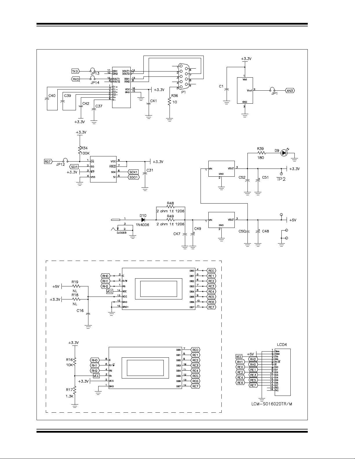
PICDEM.net™ 2 Development Board User’s Guide
FIGURE A-4: PICDEM.net 2 DEVELOPMENT BOARD SCHEMATIC, SHEET 4 OF 5 (RS-232,
EEPROM, TEMPERATURE SENSOR, LCD OPTIONS AND POWER SUPPLY)
U5
MAX3232
U1
TC1047
.1 μF
.1 μF
.1 μF
.1 μF
.1 μF
U4
25LC256
.1 μF
.1 μF
Temperature Sensor
Q2 TC1262-3.3VEB
.1 μF
47 μF
Alternate LCD Configurations
.1 μF
J7
.1 μF
LCD1
LCD2
Q1 LM2940S-5.0
220 μF
.1 μF
47 μF
TP4
TP3
TP5
DS51623B-page 40 © 2007 Microchip Technology Inc.
Page 45

PICDEM.net 2 Development Board Schematics, Rev. 4
FIGURE A-5: PICDEM.net 2 DEVELOPMENT BOARD SCHEMATIC, SHEET 5 OF 5 (ICD,
ICSP™, LCD DISPLAY, MICROCONTROLLER HEADER AND PICtail™
DAUGHTER BOARD CONNECTORS)
J3
4.7 μF
4.7 μF
1 μF
1 μF
LCD Character
Display Port
4.7 μF
4.7 μF
1 μF
1 μF
1 μF
J4
J5
PICtail™
Daughter
Board
J6
.1 μF
ICD Connector
© 2007 Microchip Technology Inc. DS51623B-page 41
Page 46

PICDEM.net™ 2 Development Board User’s Guide
NOTES:
DS51623B-page 42 © 2007 Microchip Technology Inc.
Page 47

PICDEM.net™ 2 DEVELOPMENT
BOARD USER’S GUIDE
Index
A
AN833, The Microchip TCP/IP Stack....................... 21
ARP Caching ........................................................... 29
C
Changing the Default IP Configuration .................... 22
Changing the FTP Login Account ............................ 22
Configuring the PICDEM.net 2
Development Board.............................................. 16
Configuring the Host IP Address ...................... 18
Obtaining the Host IP Address ......................... 16
Connecting the PICDEM.net 2
Development Board ................................................. 13
Confirming Operation........................................ 16
Connected to a Network ................................... 14
Connecting Directly to a Host System .............. 15
Customer Notification Service.................................... 4
Customer Support...................................................... 5
D
Demo Web Site.......................................20, 28, 34, 35
Experimenting................................................... 23
Development Kit CD ................................................ 10
Development Kit Contents ......................................... 7
Documentation
Conventions........................................................ 2
Layout ................................................................. 1
Dynamic Host Configuration
Protocol (DHCP) ...........................................11
, 21, 29
E
ENC28J60
Operation .......................................................... 27
Use as the Ethernet Interface ........................... 27
Establishing Communications.................................. 19
Ethernet
ID Stickers (Serial Numbers) ............................ 10
Ethernet Controller
ENC28J60 .......................................................... 8
Ethernet Crossover Cable.............................14
Ethernet Integrated Connector Module (ICM)............ 9
, 15, 33
F
File Transfer Protocol (FTP)..................................... 21
FTP
Loading a Web Site .......................................... 30
Service Unavailable Message .......................... 35
H
HyperText Transfer Protocol (HTTP) ....................... 21
Hypertext Transfer Protocol (HTTP) ........................ 12
I
Internet Address......................................................... 4
IP Gleaning ...................................................19
, 21, 29
L
LCD
Display ................................................................ 8
Optional External Connector............................... 9
LCD Display ....................................................... 16
LEDs
Power-on............................................................. 9
User-Defined....................................................... 9
Local Host System ................................................... 12
, 33
M
MAC Address ........................................................... 10
Memory
External EEPROM ..................... 18, 21, 23, 30, 34
External EEPROM (25LC256) ............................ 8
MCU Program ............................................. 28
Microchip Internet Web Site ....................................... 4
Microchip TCP/IP Stack ..................................3, 19, 21
Experimenting with Demo
Application Firmware ........................................ 22
Installing the Source Code................................ 21
Microcontroller
PIC18F97J60...................................................... 8
Modular Connector..................................................... 9
MPFS Utility ............................................................. 23
, 31
N
Networking Precautions ........................................... 11
O
On-Board Power ........................................................ 9
P
PICtail Daughter Board .............................................. 9
Potentiometers
User-Defined....................................................... 9
Prototype Area ........................................................... 9
Push Buttons
Reset............................................................. 9
User-Defined................................................. 9
, 28
, 28
R
Recommended Reading ............................................ 3
“ENC28J60 Data Sheet” ..................................... 3
“PIC18F97J60 Family Data Sheet” ..................... 3
AN833, “The Microchip TCP/IP Stack” ............... 3
Readme Files...................................................... 3
© 2007 Microchip Technology Inc. DS51623B-page 43
Page 48

PICDEM.net™ 2 Development Board User’s Guide
Reconfiguring PICDEM.net 2 Development Board
Firmware ...........................................................28
Changing Network Configuration............... 29
Entering Configuration Mode ..................... 28
Loading/Reloading the Web Page ............. 30
Hardware .......................................................... 25
Ethernet LEDs ........................................... 27
Timer1 Oscillator (Y3)................................ 27
User-Defined Controls and the
LED Bank................................................... 27
Reprogramming and Restoring the Firmware .......... 31
Revision History ......................................................... 5
S
Schematics
PICDEM.net 2 Development Board ............ 37
Serial Configuration
Loading a Web Site........................................... 30
Serial Port .................................................................. 9
–41
T
Temperature Sensor
TC1047 ...............................................................9
Troubleshooting
Changing IP Address and/or Ethernet ID.......... 34
Communications ............................................... 34
Demo Web Site .................................................34
LCD Display ...................................................... 33
LED D8..............................................................33
Link LED............................................................33
Serial Configuration...........................................35
Services Unavailable.........................................35
W
Warranty Registration.................................................3
WWW Address ...........................................................4
DS51623B-page 44 © 2007 Microchip Technology Inc.
Page 49

NOTES:
Index
© 2007 Microchip Technology Inc. DS51623B-page 45
Page 50

WORLDWIDE SALES AND SERVICE
AMERICAS
Corporate Office
2355 West Chandler Blvd.
Chandler, AZ 85224-6199
Tel: 480-792-7200
Fax: 480-792-7277
Technical Support:
http://support.microchip.com
Web Address:
www.microchip.com
Atlanta
Duluth, GA
Tel: 678-957-9614
Fax: 678-957-1455
Boston
Westborough, MA
Tel: 774-760-0087
Fax: 774-760-0088
Chicago
Itasca, IL
Tel: 630-285-0071
Fax: 630-285-0075
Dallas
Addison, TX
Tel: 972-818-7423
Fax: 972-818-2924
Detroit
Farmington Hills, MI
Tel: 248-538-2250
Fax: 248-538-2260
Kokomo
Kokomo, IN
Tel: 765-864-8360
Fax: 765-864-8387
Los Angeles
Mission Viejo, CA
Tel: 949-462-9523
Fax: 949-462-9608
Santa Clara
Santa Clara, CA
Tel: 408-961-6444
Fax: 408-961-6445
Toronto
Mississauga, Ontario,
Canada
Tel: 905-673-0699
Fax: 905-673-6509
ASIA/PACIFIC
Asia Pacific Office
Suites 3707-14, 37th Floor
Tower 6, The Gateway
Harbour City, Kowloon
Hong Kong
Tel: 852-2401-1200
Fax: 852-2401-3431
Australia - Sydney
Tel: 61-2-9868-6733
Fax: 61-2-9868-6755
China - Beijing
Tel: 86-10-8528-2100
Fax: 86-10-8528-2104
China - Chengdu
Tel: 86-28-8665-5511
Fax: 86-28-8665-7889
China - Fuzhou
Tel: 86-591-8750-3506
Fax: 86-591-8750-3521
China - Hong Kong SAR
Tel: 852-2401-1200
Fax: 852-2401-3431
China - Qingdao
Tel: 86-532-8502-7355
Fax: 86-532-8502-7205
China - Shanghai
Tel: 86-21-5407-5533
Fax: 86-21-5407-5066
China - Shenyang
Tel: 86-24-2334-2829
Fax: 86-24-2334-2393
China - Shenzhen
Tel: 86-755-8203-2660
Fax: 86-755-8203-1760
China - Shunde
Tel: 86-757-2839-5507
Fax: 86-757-2839-5571
China - Wuhan
Tel: 86-27-5980-5300
Fax: 86-27-5980-5118
China - Xian
Tel: 86-29-8833-7252
Fax: 86-29-8833-7256
ASIA/PACIFIC
India - Bangalore
Tel: 91-80-4182-8400
Fax: 91-80-4182-8422
India - New Delhi
Tel: 91-11-4160-8631
Fax: 91-11-4160-8632
India - Pune
Tel: 91-20-2566-1512
Fax: 91-20-2566-1513
Japan - Yokohama
Tel: 81-45-471- 6166
Fax: 81-45-471-6122
Korea - Daegu
Tel: 82-53-744-4301
Fax: 82-53-744-4302
Korea - Seoul
Tel: 82-2-554-7200
Fax: 82-2-558-5932 or
82-2-558-5934
Malaysia - Penang
Tel: 60-4-646-8870
Fax: 60-4-646-5086
Philippines - Manila
Tel: 63-2-634-9065
Fax: 63-2-634-9069
Singapore
Tel: 65-6334-8870
Fax: 65-6334-8850
Taiwan - Hsin Chu
Tel: 886-3-572-9526
Fax: 886-3-572-6459
Taiwan - Kaohsiung
Tel: 886-7-536-4818
Fax: 886-7-536-4803
Taiwan - Taipei
Tel: 886-2-2500-6610
Fax: 886-2-2508-0102
Thailand - Bangkok
Tel: 66-2-694-1351
Fax: 66-2-694-1350
EUROPE
Austria - Wels
Tel: 43-7242-2244-39
Fax: 43-7242-2244-393
Denmark - Copenhagen
Tel: 45-4450-2828
Fax: 45-4485-2829
France - Paris
Tel: 33-1-69-53-63-20
Fax: 33-1-69-30-90-79
Germany - Munich
Tel: 49-89-627-144-0
Fax: 49-89-627-144-44
Italy - Milan
Tel: 39-0331-742611
Fax: 39-0331-466781
Netherlands - Drunen
Tel: 31-416-690399
Fax: 31-416-690340
Spain - Madrid
Tel: 34-91-708-08-90
Fax: 34-91-708-08-91
UK - Wokingham
Tel: 44-118-921-5869
Fax: 44-118-921-5820
06/25/07
DS51623B-page 46 © 2007 Microchip Technology Inc.
 Loading...